EP1787726A2 - Applicator - Google Patents
Applicator Download PDFInfo
- Publication number
- EP1787726A2 EP1787726A2 EP06255817A EP06255817A EP1787726A2 EP 1787726 A2 EP1787726 A2 EP 1787726A2 EP 06255817 A EP06255817 A EP 06255817A EP 06255817 A EP06255817 A EP 06255817A EP 1787726 A2 EP1787726 A2 EP 1787726A2
- Authority
- EP
- European Patent Office
- Prior art keywords
- applicator
- face
- upper body
- fibrous base
- jaw
- Prior art date
- Legal status (The legal status is an assumption and is not a legal conclusion. Google has not performed a legal analysis and makes no representation as to the accuracy of the status listed.)
- Withdrawn
Links
Images



Classifications
-
- B—PERFORMING OPERATIONS; TRANSPORTING
- B05—SPRAYING OR ATOMISING IN GENERAL; APPLYING FLUENT MATERIALS TO SURFACES, IN GENERAL
- B05C—APPARATUS FOR APPLYING FLUENT MATERIALS TO SURFACES, IN GENERAL
- B05C17/00—Hand tools or apparatus using hand held tools, for applying liquids or other fluent materials to, for spreading applied liquids or other fluent materials on, or for partially removing applied liquids or other fluent materials from, surfaces
-
- A—HUMAN NECESSITIES
- A47—FURNITURE; DOMESTIC ARTICLES OR APPLIANCES; COFFEE MILLS; SPICE MILLS; SUCTION CLEANERS IN GENERAL
- A47L—DOMESTIC WASHING OR CLEANING; SUCTION CLEANERS IN GENERAL
- A47L13/00—Implements for cleaning floors, carpets, furniture, walls, or wall coverings
- A47L13/10—Scrubbing; Scouring; Cleaning; Polishing
- A47L13/16—Cloths; Pads; Sponges
-
- A—HUMAN NECESSITIES
- A47—FURNITURE; DOMESTIC ARTICLES OR APPLIANCES; COFFEE MILLS; SPICE MILLS; SUCTION CLEANERS IN GENERAL
- A47L—DOMESTIC WASHING OR CLEANING; SUCTION CLEANERS IN GENERAL
- A47L13/00—Implements for cleaning floors, carpets, furniture, walls, or wall coverings
- A47L13/10—Scrubbing; Scouring; Cleaning; Polishing
- A47L13/50—Auxiliary implements
- A47L13/51—Storing of cleaning tools, e.g. containers therefor
-
- B—PERFORMING OPERATIONS; TRANSPORTING
- B44—DECORATIVE ARTS
- B44D—PAINTING OR ARTISTIC DRAWING, NOT OTHERWISE PROVIDED FOR; PRESERVING PAINTINGS; SURFACE TREATMENT TO OBTAIN SPECIAL ARTISTIC SURFACE EFFECTS OR FINISHES
- B44D3/00—Accessories or implements for use in connection with painting or artistic drawing, not otherwise provided for; Methods or devices for colour determination, selection, or synthesis, e.g. use of colour tables
- B44D3/12—Paint cans; Brush holders; Containers for storing residual paint
- B44D3/127—Covers or lids for paint cans
-
- B—PERFORMING OPERATIONS; TRANSPORTING
- B44—DECORATIVE ARTS
- B44D—PAINTING OR ARTISTIC DRAWING, NOT OTHERWISE PROVIDED FOR; PRESERVING PAINTINGS; SURFACE TREATMENT TO OBTAIN SPECIAL ARTISTIC SURFACE EFFECTS OR FINISHES
- B44D3/00—Accessories or implements for use in connection with painting or artistic drawing, not otherwise provided for; Methods or devices for colour determination, selection, or synthesis, e.g. use of colour tables
- B44D3/12—Paint cans; Brush holders; Containers for storing residual paint
- B44D3/128—Wiping bars; Rim protectors; Drip trays; Spill catchers
-
- E—FIXED CONSTRUCTIONS
- E04—BUILDING
- E04F—FINISHING WORK ON BUILDINGS, e.g. STAIRS, FLOORS
- E04F21/00—Implements for finishing work on buildings
- E04F21/02—Implements for finishing work on buildings for applying plasticised masses to surfaces, e.g. plastering walls
- E04F21/06—Implements for applying plaster, insulating material, or the like
Definitions
- the present invention relates to an applicator for applying a coating material (eg varnish) to a substrate and to a kit comprising the applicator.
- a coating material eg varnish
- Applicators for applying coatings such as stains and varnishes to a substrate such as a wall, furniture or a floor.
- Applicators which are operable whilst being held at a position remote from the substrate include brushes, rollers and sprays.
- Applicators which are operable whilst being held at a position intimate with the substrate include pads and cloths.
- the present invention seeks to improve the application of a coating material to a substrate by exploiting an applicator which is configured to be palm-driven intimately to the substrate.
- an applicator for applying a coating material to a substrate comprising:
- the applicator of the invention exhibits the versatility of a brush but has the ability to coat a substrate more rapidly and to be more manoeuvrable into awkward positions such as panelling corners and intricate mouldings.
- the applicator is easy to hold and permits coverage of large areas (such as doors, skirting, furniture and bannisters) without brush or lap marks.
- the applicator is disassemblable. In a disassembled form, the applicator may be stored in a compact manner.
- the upper body is ergonomically configured to be palm-mounted thereby allowing the applicator to be palm-driven.
- the upper body is dimensionally configured to be palm-mounted.
- the profile of the upper body is configured to be palm-driven.
- the upper body is substantially shoe-like.
- the upper body is a substantially part (eg semi-) anvil-like.
- the upper body has a leading face opposite to a trailing face and spaced apart therefrom by opposed side faces, an upper face and a lower face.
- the leading face is frontwardly facing and the trailing face is rearwardly facing.
- the leading face is preferably at least partially concave (preferably longitudinally concave). This assists one or more digits to hold and drive the upper body and facilitates manoeuverability. At least a part of the surface of the or each side face may be tapered inwardly (eg rearwardly tapered inwardly). At least a part of the surface of the or (preferably) each side face may be modified for gripping. Typically the at least a part of the surface of the or each side face is roughened, striated, ridged or nodular for gripping.
- the trailing face may be convex (preferably longitudinally convex) or squared.
- the upper face is typically convex (preferably transversely convex).
- the upper face typically tapers downwardly from the leading to the trailing edge.
- the lower face is typically substantially planar and polygonal.
- the lower face is substantially quadrilateral, particularly preferably rectangular.
- the upper body comprises: an upper jaw and a lower jaw, the upper jaw and lower jaw defining a mouth (eg a reentrant mouth) adapted to receive one or more digits.
- the upper jaw and lower jaw are typically rearwardly projecting.
- the upper jaw and lower jaw may be convergent at the rear of the mouth.
- the upper and lower jaw preferably converge to a curved intersect (eg an elliptical intersect).
- the curved intersect preferably terminates at or near to the leading face.
- the interior face of each of the upper jaw and lower jaw is preferably transversely convex.
- the corners of the leading edge of the upper jaw may be rounded.
- the sides of the upper jaw may be tapered inwardly (eg rearwardly tapered inwardly).
- the upper body consists of a detachable (preferably longitudinally detachable) first part and second part. Particularly preferably the upper body is longitudinally bisectional.
- the first part and second part may be attached detachably by a plurality of male and female engaging portions.
- the inner edge of the first part may comprise a plurality of resilient tangs and the inner edge of the second part may comprise an inner sleeve with cut-away portions, wherein the cut-away portions are positionally and dimensionally coincident with the resilient tangs to engage therewith.
- the at least partially fibrous base comprises:
- the fibrous base member may be coupled to the lower face of the upper body in a longitudinally offset manner.
- the substantially planar coupling member may be capable of detachably coupling the lower face of the upper body to the fibrous base member. This advantageously permits the operator in use to detach (eg momentarily detach) the fibrous base member to be used in isolation from the upper body to coat otherwise inaccessible areas eg intricate mouldings or staircase spindles.
- the fibrous base member has a leading face opposite to a trailing face and spaced apart therefrom by opposed side faces, an upper face and a lower face,
- the leading face is frontwardly facing and the trailing face is rearwardly facing.
- the leading face of the fibrous base member is downwardly tapered.
- one or both side faces of the fibrous base member is downwardly tapered.
- Downwardly tapering faces of the fibrous base member are advantageously disposed to reach into the square corners of mouldings and the edges around the panels of a panelled surface.
- the trailing face may be non-tapered.
- the leading face may be angled to create a leading point.
- the shape of the fibrous base member is substantially truncated rectangular (eg square) pyramidal.
- the shape of the fibrous member is substantially truncated rectangular (eg square) pyramidal with a substantially squared trailing face.
- the fibrous member may be composed of sponge, textile or flock.
- a preferred fibrous base member is a flock covered sponge member. Such a fibrous base member is found to give a better coating finish and be advantageously more mainuplable.
- the substantially planar coupling member may be attached or adhered to the upper face of the fibrous base member.
- the substantially planar coupling member and the lower face of the upper body may be attached detachably by a plurality of male and female engaging portions.
- the substantially planar coupling member may comprise a resilient collar and the lower face may comprise a skirt, wherein the resilient collar is positionally and dimensionally coincident with the skirt to engage therewith.
- the skirt and resilient collar may be substantially rectangular.
- the resilient collar may be mounted on (or be integral with) a plate which is fastened to the upper face of the fibrous base member.
- the present invention also exploits the embodiment of the applicator of the invention in disassembled form in an improved kit of parts of independent patentable significance.
- the present invention provides a kit comprising:
- the overlid may be opaque, semi-transparent or transparent. Due to the inherent strength of the kit, the overlid need not be overtly strong to withstand pressure during stacking and storage.
- the overlid is typically interiorly moulded to confine the applicator in disassembled form.
- the overlid is exteriorly adapted to be stackable with the base of an adjacent container.
- the applicator is one wherein the upper body consists of a detachable (preferably longitudinally detachable, more preferably longitudinally bisectional) first and second part and wherein the at least partially fibrous base is detachably attached to the upper body, wherein the detached first part, second part and at least partially fibrous base are intimately seated on the lid.
- the detachable nature of the upper body and of the at least partially fibrous base ensures that within the lid the applicator does not project unduly. This enhances stackability of the kit and minimises storage volumes.
- the first part and second part are seated astride the at least partially fibrous base on the lid.
- the at least partially fibrous base may be seated upright on the lid.
- the first part and second part of the upper body may be seated recumbent on the lid.
- the first part and second part of the upper part may be disposed substantially parallel, spaced apart.
- the applicator is one in which the trailing face of the upper body is squared.
- the overlid and applicator may comprise male and female engaging portions.
- the lid may comprise a raised skirt which assist in confining the applicator.
- the applicator is one in which the upper body comprises: an upper jaw and a lower jaw, the upper jaw and lower jaw defining a mouth (eg a reentrant mouth) adapted to receive one or more digits, wherein the lower jaw and the wall of the overlid are provided with male and female engaging portions.
- the lower jaw may be provided with one or more nodules engageable with one or more slots in an interior wall of the overlid.
- the lid may be sealingly mounted detachably on the container.
- the overlid may be mounted detachably on the lid by a resilient collar engaging the raised skirt on the lid.
- the coating material may be liquid or semi-liquid. Specific examples includes paint, varnish, dye or stain.
- Figure 1 illustrates an embodiment of the applicator of the invention 1 in disassembled form.
- the applicator 1 comprises generally an upper body 2 which is ergonomically configured both dimensionally and shapewise to be palm-mounted (and is described in detail below with reference to Figure 2) and a fibrous base 100.
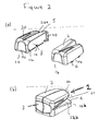
- Figures 2a and 2b illustrate respectively in disassembled and assembled form the upper body 2. From Figure 2b, it will be apparent that the upper body is substantially shoe-like or semi-anvil-like so as to be palm-mounted.
- the upper body 2 has a concave leading face 3 opposite to a convex trailing face 4, a convex upper face 7 which tapers downwardly from the leading face 3 to the trailing face 4 and a rectangular lower face 8.
- the leading face 3 and trailing face 4 are spaced apart by opposed side faces 5, 6 which are inwardly tapered and provided with nodules 20 for gripping.
- the trailing face 4 is bisected into an upper jaw 4a and a lower jaw 4b which define a mouth 21.
- the interior face 24a, 24b of each of the upper jaw 4a and lower jaw 4b is convex.
- the corners of the upper body 2 are in general rounded or chamfered.
- the upper body 2 is longitudinally bisectional into a first part 1a and a second part 1b.
- An inner edge 11b of the second part 1b comprises a plurality of resilient tangs 12 and the inner edge 11a of the first part 1 a comprises an inner sleeve 11c with cut-away portions 13 which are positionally and dimensionally coincident with the resilient tangs 12 to engage therewith.
- the parts 1a and 1b are engageable with a snap-fit action but easily detached.
- the fibrous base 100 comprises generally a fibrous base member 101 in the form of a flock covered sponge 112 which is infusible with coating material and a substantially planar coupling member 102.
- the shape of the fibrous base member 101 is substantially truncated rectangular pyramidal with a substantially squared trailing face 103 and a downwardly dependent leading face 104.
- the substantially planar coupling member 102 couples detachably the lower face 8 of the upper body 2 to the fibrous base member 101 in a longitudinally offset manner.
- the substantially planar coupling member 102 comprises a resilient collar 108 and the lower face 8 comprises a skirt 110.
- the resilient collar 108 is positionally and dimensionally coincident with the skirt 110 to engage therewith.
- the resilient collar 108 is integrally formed with a plate 111 which is fastened to the upper face 107 of the fibrous base member 101.
- the applicator In use, the applicator is typically held in the palm with the convex leading face 3 forward and the forefinger, middle finger and ring finger engaged therewith.
- the little finger typically engages the mouth 21 and the thumb is seated on the nodules 20 of the side face 5. This disposition of fingers allows the upper body 2 to be palm-driven intimately to the substrate which improves speed, quality and control of coverage of a coating material.
- FIGs 3 and 4 illustrate in disassembled and assembled view respectively an embodiment of the kit of the invention 400.
- the kit 400 comprises a container 31 containing a reservoir of varnish and a lid 32 mounted detachably on the container 31.
- An applicator 1 as described above with reference to Figures 1 and 2 is seated on the lid 32 in disassembled form.
- a transparent overlid 33 (omitted from Figure 4 for clarity) is mounted detachably on the lid 32.
- a resilient collar 300 on the overlid 33 engages a raised skirt 301 on the lid 32.
- the overlid 33 is interiorly moulded substantially to the shape of the applicator 1 so as to intimately confine the applicator 1.
- the first and second part 1a, 1b of the upper body 2 of the applicator 1 are seated recumbent and parallel astride the fibrous base 100 which is seated upright.
Landscapes
- Engineering & Computer Science (AREA)
- Architecture (AREA)
- Mechanical Engineering (AREA)
- Civil Engineering (AREA)
- Structural Engineering (AREA)
- Coating Apparatus (AREA)
Abstract
Description
- The present invention relates to an applicator for applying a coating material (eg varnish) to a substrate and to a kit comprising the applicator.
- A variety of applicators are known for applying coatings such as stains and varnishes to a substrate such as a wall, furniture or a floor. Applicators which are operable whilst being held at a position remote from the substrate include brushes, rollers and sprays. Applicators which are operable whilst being held at a position intimate with the substrate include pads and cloths.
- It is known to provide applicators, coating material and other components in kit form. Examples are given in
EP-A-1293360 ,DE20011439U1 andDE10322768A1 . - The present invention seeks to improve the application of a coating material to a substrate by exploiting an applicator which is configured to be palm-driven intimately to the substrate.
- Thus viewed from one aspect the present invention provides an applicator for applying a coating material to a substrate comprising:
- a handheld upper body configured to be palm-mounted; and
- an at least partially fibrous base which is attached to the upper body and is infusible with the coating material.
- The applicator of the invention exhibits the versatility of a brush but has the ability to coat a substrate more rapidly and to be more manoeuvrable into awkward positions such as panelling corners and intricate mouldings. The applicator is easy to hold and permits coverage of large areas (such as doors, skirting, furniture and bannisters) without brush or lap marks.
- In a preferred embodiment, the applicator is disassemblable. In a disassembled form, the applicator may be stored in a compact manner.
- Typically the upper body is ergonomically configured to be palm-mounted thereby allowing the applicator to be palm-driven. Preferably the upper body is dimensionally configured to be palm-mounted. Preferably the profile of the upper body is configured to be palm-driven. In a preferred embodiment, the upper body is substantially shoe-like. In a preferred embodiment, the upper body is a substantially part (eg semi-) anvil-like.
- Generally speaking, the upper body has a leading face opposite to a trailing face and spaced apart therefrom by opposed side faces, an upper face and a lower face. In use, the leading face is frontwardly facing and the trailing face is rearwardly facing.
- The leading face is preferably at least partially concave (preferably longitudinally concave). This assists one or more digits to hold and drive the upper body and facilitates manoeuverability. At least a part of the surface of the or each side face may be tapered inwardly (eg rearwardly tapered inwardly). At least a part of the surface of the or (preferably) each side face may be modified for gripping. Typically the at least a part of the surface of the or each side face is roughened, striated, ridged or nodular for gripping. The trailing face may be convex (preferably longitudinally convex) or squared.
- The upper face is typically convex (preferably transversely convex). The upper face typically tapers downwardly from the leading to the trailing edge.
- The lower face is typically substantially planar and polygonal. Preferably the lower face is substantially quadrilateral, particularly preferably rectangular.
- Preferably the upper body comprises: an upper jaw and a lower jaw, the upper jaw and lower jaw defining a mouth (eg a reentrant mouth) adapted to receive one or more digits. In use, the upper jaw and lower jaw are typically rearwardly projecting.
- The upper jaw and lower jaw may be convergent at the rear of the mouth. The upper and lower jaw preferably converge to a curved intersect (eg an elliptical intersect). The curved intersect preferably terminates at or near to the leading face. The interior face of each of the upper jaw and lower jaw is preferably transversely convex.
- The corners of the leading edge of the upper jaw may be rounded. The sides of the upper jaw may be tapered inwardly (eg rearwardly tapered inwardly).
- In a preferred embodiment, the upper body consists of a detachable (preferably longitudinally detachable) first part and second part. Particularly preferably the upper body is longitudinally bisectional.
- The first part and second part may be attached detachably by a plurality of male and female engaging portions. The inner edge of the first part may comprise a plurality of resilient tangs and the inner edge of the second part may comprise an inner sleeve with cut-away portions, wherein the cut-away portions are positionally and dimensionally coincident with the resilient tangs to engage therewith.
- In a preferred embodiment, the at least partially fibrous base comprises:
- a fibrous base member which is infusible with the coating material; and
- a substantially planar coupling member capable of coupling the lower face of the upper body to the fibrous base member.
- The fibrous base member may be coupled to the lower face of the upper body in a longitudinally offset manner. The substantially planar coupling member may be capable of detachably coupling the lower face of the upper body to the fibrous base member. This advantageously permits the operator in use to detach (eg momentarily detach) the fibrous base member to be used in isolation from the upper body to coat otherwise inaccessible areas eg intricate mouldings or staircase spindles.
- Generally speaking, the fibrous base member has a leading face opposite to a trailing face and spaced apart therefrom by opposed side faces, an upper face and a lower face, In use, the leading face is frontwardly facing and the trailing face is rearwardly facing. Preferably the leading face of the fibrous base member is downwardly tapered. Preferably one or both side faces of the fibrous base member is downwardly tapered. Downwardly tapering faces of the fibrous base member are advantageously disposed to reach into the square corners of mouldings and the edges around the panels of a panelled surface. The trailing face may be non-tapered. The leading face may be angled to create a leading point.
- Preferably the shape of the fibrous base member is substantially truncated rectangular (eg square) pyramidal. Particularly preferably the shape of the fibrous member is substantially truncated rectangular (eg square) pyramidal with a substantially squared trailing face.
- The fibrous member may be composed of sponge, textile or flock. A preferred fibrous base member is a flock covered sponge member. Such a fibrous base member is found to give a better coating finish and be advantageously more mainuplable.
- The substantially planar coupling member may be attached or adhered to the upper face of the fibrous base member. The substantially planar coupling member and the lower face of the upper body may be attached detachably by a plurality of male and female engaging portions. The substantially planar coupling member may comprise a resilient collar and the lower face may comprise a skirt, wherein the resilient collar is positionally and dimensionally coincident with the skirt to engage therewith. The skirt and resilient collar may be substantially rectangular. The resilient collar may be mounted on (or be integral with) a plate which is fastened to the upper face of the fibrous base member.
- The present invention also exploits the embodiment of the applicator of the invention in disassembled form in an improved kit of parts of independent patentable significance.
- Viewed from a further aspect the present invention provides a kit comprising:
- a container for a reservoir of coating material;
- a lid mounted detachably on the container;
- an applicator in disassembled form as hereinbefore defined seated on the lid; and
- an overlid mounted detachably on the lid, wherein the overlid is interiorly configured to confine the applicator in disassembled form.
- The overlid may be opaque, semi-transparent or transparent. Due to the inherent strength of the kit, the overlid need not be overtly strong to withstand pressure during stacking and storage.
- The overlid is typically interiorly moulded to confine the applicator in disassembled form.
- Preferably the overlid is exteriorly adapted to be stackable with the base of an adjacent container.
- In a preferred kit of the invention, the applicator is one wherein the upper body consists of a detachable (preferably longitudinally detachable, more preferably longitudinally bisectional) first and second part and wherein the at least partially fibrous base is detachably attached to the upper body, wherein the detached first part, second part and at least partially fibrous base are intimately seated on the lid. In this embodiment, the detachable nature of the upper body and of the at least partially fibrous base ensures that within the lid the applicator does not project unduly. This enhances stackability of the kit and minimises storage volumes. In a particularly preferred kit of the invention, the first part and second part are seated astride the at least partially fibrous base on the lid.
- The at least partially fibrous base may be seated upright on the lid. The first part and second part of the upper body may be seated recumbent on the lid. The first part and second part of the upper part may be disposed substantially parallel, spaced apart.
- In a preferred kit of the invention, the applicator is one in which the trailing face of the upper body is squared.
- To facilitate the confinement of the applicator in the overlid, the overlid and applicator may comprise male and female engaging portions. The lid may comprise a raised skirt which assist in confining the applicator.
- In a preferred kit of the invention, the applicator is one in which the upper body comprises: an upper jaw and a lower jaw, the upper jaw and lower jaw defining a mouth (eg a reentrant mouth) adapted to receive one or more digits, wherein the lower jaw and the wall of the overlid are provided with male and female engaging portions. For example, the lower jaw may be provided with one or more nodules engageable with one or more slots in an interior wall of the overlid.
- The lid may be sealingly mounted detachably on the container. The overlid may be mounted detachably on the lid by a resilient collar engaging the raised skirt on the lid.
- The coating material may be liquid or semi-liquid. Specific examples includes paint, varnish, dye or stain.
- The present invention will now be described in a non-limitative sense with reference to the accompanying figures in which:
- Figure 1 illustrates an embodiment of the applicator of the invention in disassembled form;
- Figures 2a and 2b illustrate respectively in disassembled and assembled form the upper body of the embodiment of Figure 1;
- Figure 3 illustrates a disassembled view of an embodiment of the kit of the invention; and
- Figure 4 illustrates an assembled view of the embodiment of the kit of the invention.
- Figure 1 illustrates an embodiment of the applicator of the
invention 1 in disassembled form. Theapplicator 1 comprises generally anupper body 2 which is ergonomically configured both dimensionally and shapewise to be palm-mounted (and is described in detail below with reference to Figure 2) and afibrous base 100. - Figures 2a and 2b illustrate respectively in disassembled and assembled form the
upper body 2. From Figure 2b, it will be apparent that the upper body is substantially shoe-like or semi-anvil-like so as to be palm-mounted. Theupper body 2 has a concaveleading face 3 opposite to aconvex trailing face 4, a convexupper face 7 which tapers downwardly from the leadingface 3 to the trailingface 4 and a rectangularlower face 8. The leadingface 3 and trailingface 4 are spaced apart by opposed side faces 5, 6 which are inwardly tapered and provided withnodules 20 for gripping. - The trailing
face 4 is bisected into an upper jaw 4a and a lower jaw 4b which define amouth 21. The interior face 24a, 24b of each of the upper jaw 4a and lower jaw 4b is convex. The corners of theupper body 2 are in general rounded or chamfered. - As will be apparent from Figure 2a, the
upper body 2 is longitudinally bisectional into a first part 1a and asecond part 1b. An inner edge 11b of thesecond part 1b comprises a plurality ofresilient tangs 12 and the inner edge 11a of the first part 1 a comprises an inner sleeve 11c with cut-awayportions 13 which are positionally and dimensionally coincident with theresilient tangs 12 to engage therewith. Theparts 1a and 1b are engageable with a snap-fit action but easily detached. - The
fibrous base 100 comprises generally afibrous base member 101 in the form of a flock coveredsponge 112 which is infusible with coating material and a substantiallyplanar coupling member 102. The shape of thefibrous base member 101 is substantially truncated rectangular pyramidal with a substantially squared trailingface 103 and a downwardly dependent leadingface 104. - The substantially
planar coupling member 102 couples detachably thelower face 8 of theupper body 2 to thefibrous base member 101 in a longitudinally offset manner. For this purpose, the substantiallyplanar coupling member 102 comprises aresilient collar 108 and thelower face 8 comprises askirt 110. Theresilient collar 108 is positionally and dimensionally coincident with theskirt 110 to engage therewith. Theresilient collar 108 is integrally formed with aplate 111 which is fastened to theupper face 107 of thefibrous base member 101. - In use, the applicator is typically held in the palm with the convex
leading face 3 forward and the forefinger, middle finger and ring finger engaged therewith. The little finger typically engages themouth 21 and the thumb is seated on thenodules 20 of the side face 5. This disposition of fingers allows theupper body 2 to be palm-driven intimately to the substrate which improves speed, quality and control of coverage of a coating material. - Figures 3 and 4 illustrate in disassembled and assembled view respectively an embodiment of the kit of the
invention 400. Thekit 400 comprises acontainer 31 containing a reservoir of varnish and alid 32 mounted detachably on thecontainer 31. Anapplicator 1 as described above with reference to Figures 1 and 2 is seated on thelid 32 in disassembled form. A transparent overlid 33 (omitted from Figure 4 for clarity) is mounted detachably on thelid 32. For this purpose aresilient collar 300 on theoverlid 33 engages a raisedskirt 301 on thelid 32. Theoverlid 33 is interiorly moulded substantially to the shape of theapplicator 1 so as to intimately confine theapplicator 1. - The first and
second part 1a, 1b of theupper body 2 of theapplicator 1 are seated recumbent and parallel astride thefibrous base 100 which is seated upright.
Claims (33)
- An applicator for applying a coating material to a substrate comprising;a handheld upper body configured to be palm-mounted; andan at least partially fibrous base which is attached to the upper body and is infusible with the coating material.
- An applicator as claimed in claim 1 which is disassemblable.
- An applicator as claimed in claim 1 or 2 wherein the upper body is dimensionally configured to be palm-mounted.
- An applicator as claimed in any preceding claim wherein the profile of the upper body is configured to be palm-driven.
- An applicator as claimed in any preceding claim wherein the upper body is substantially shoe-like.
- An applicator as claimed in any preceding claim wherein the upper body is substantially part anvil-like.
- An applicator as claimed in any preceding claim wherein the upper body has a leading face opposite to a trailing face and spaced apart therefrom by opposed side faces, an upper face and a lower face, wherein in use the leading face is frontwardly facing and the trailing face is rearwardly facing, wherein the leading face is at least partially concave
- An applicator as claimed in claim 7 wherein the leading face is longitudinally concave.
- An applicator as claimed in claim 7 or 8 wherein at least a part of the surface of the or each side face is tapered inwardly.
- An applicator as claimed in claim 7, 8 or 9 wherein at least a part of the surface of the or each side face is modified for gripping.
- An applicator as claimed in any of claims 7 to 10 wherein the trailing face is longitudinally convex or squared.
- An applicator as claimed in any of claims 7 to 11 wherein the upper face is transversely convex.
- An applicator as claimed in any of claims 7 to 12 wherein the lower face is substantially rectangular.
- An applicator as claimed in any preceding claim wherein the upper body comprises:an upper jaw and a lower jaw, the upper jaw and lower jaw defining a mouth adapted to receive one or more digits.
- An applicator as claimed in claim 14 wherein the upper and lower jaw converge to a curved intersect.
- An applicator as claimed in claim 15 wherein the curved intersect terminates at or near to the leading face.
- An applicator as claimed in any of claims 14 to 16 wherein the interior face of each of the upper jaw and lower jaw is transversely convex.
- An applicator as claimed in any preceding claim wherein the upper body consists of a longitudinally detachable first part and second part.
- An applicator as claimed in preceding claim wherein the upper body is longitudinally bisectional.
- An applicator as claimed in claim 18 wherein an inner edge of the first part comprises a plurality of resilient tangs and an inner edge of the second part comprises an inner sleeve with cut-away portions, wherein the cut-away portions are positionally and dimensionally coincident with the resilient tangs to engage therewith.
- An applicator as claimed in preceding claim wherein the at least partially fibrous base comprises:a fibrous base member which is infusible with the coating material; anda substantially planar coupling member capable of coupling the lower face of the upper body to the fibrous base member.
- An applicator as claimed in claim 21 wherein the fibrous base member is coupled to the lower face of the upper body in a longitudinally offset manner.
- An applicator as claimed in claim 21 or 22 wherein the substantially planar coupling member is capable of detachably coupling the lower face of the upper body to the fibrous base member.
- An applicator as claimed in any of claims 21 to 23 wherein the fibrous base member has a leading face opposite to a trailing face and spaced apart therefrom by opposed side faces, an upper face and a lower face, wherein in use the leading face is frontwardly facing and the trailing face is rearwardly facing, wherein the leading face of the fibrous base member is downwardly tapered.
- An applicator as claimed in any of claims 21 to 24 wherein one or both side faces of the fibrous base member is downwardly tapered.
- An applicator as claimed in any of claims 21 to 25 wherein the shape of the fibrous base member is substantially truncated rectangular pyramidal.
- An applicator as claimed in claim 26 wherein the shape of the fibrous member is substantially truncated rectangular pyramidal with a substantially squared trailing face.
- An applicator as claimed in any of claims 21 to 27 wherein the substantially planar coupling member comprises a resilient collar and the lower face of the upper body comprises a skirt, wherein the resilient collar is positionally and dimensionally coincident with the skirt to engage therewith.
- A kit comprising:a container for a reservoir of coating material;a lid mounted detachably on the container;an applicator in disassembled form as defined in any preceding claim seated on the lid; andan overlid mounted detachably on the lid, wherein the overlid is interiorly configured to confine the applicator in disassembled form.
- A kit as claimed in claim 29 wherein the overlid is exteriorly adapted to be stackable with the base of an adjacent container.
- A kit as claimed in claim 29 or 30 wherein the applicator is one wherein the upper body consists of a detachable first and second part and wherein the at least partially fibrous base is detachably attached to the upper body, wherein the detached first part, second part and at least partially fibrous base are intimately seated on the lid.
- A kit as claimed in claim 31 wherein the first part and second part are seated astride the at least partially fibrous base on the lid.
- A kit as claimed in any of claims 29 to 32 wherein the applicator is one in which the upper body comprises:an upper jaw and a lower jaw, the upper jaw and lower jaw defining a reentrant mouth adapted to receive one or more digits, wherein the lower jaw and the wall of the overlid are provided with male and female engaging portions.
Applications Claiming Priority (1)
| Application Number | Priority Date | Filing Date | Title |
|---|---|---|---|
| GB0523520A GB0523520D0 (en) | 2005-11-18 | 2005-11-18 | Applicator |
Publications (2)
| Publication Number | Publication Date |
|---|---|
| EP1787726A2 true EP1787726A2 (en) | 2007-05-23 |
| EP1787726A3 EP1787726A3 (en) | 2010-12-22 |
Family
ID=35580290
Family Applications (1)
| Application Number | Title | Priority Date | Filing Date |
|---|---|---|---|
| EP06255817A Withdrawn EP1787726A3 (en) | 2005-11-18 | 2006-11-14 | Applicator |
Country Status (2)
| Country | Link |
|---|---|
| EP (1) | EP1787726A3 (en) |
| GB (1) | GB0523520D0 (en) |
Family Cites Families (9)
| Publication number | Priority date | Publication date | Assignee | Title |
|---|---|---|---|---|
| US3883897A (en) * | 1973-12-11 | 1975-05-20 | Saul Lefkowitz | Painting glove |
| US4466151A (en) * | 1982-06-30 | 1984-08-21 | Ppg Industries, Inc. | Applicator for applying a coating to a surface |
| GB8530588D0 (en) * | 1985-12-12 | 1986-01-22 | Reynolds D M | Wallpapering tool |
| US4996735A (en) * | 1989-07-07 | 1991-03-05 | Blankenship Linda C T | Paint design applicator |
| US6016571A (en) * | 1999-01-04 | 2000-01-25 | Guzman; Paul J. | Cooperatively-paired reticulate and sponge workgloves |
| US6145155A (en) * | 1999-01-11 | 2000-11-14 | James; Glenn P. | Double sided cleaning pad mitt with sealed package |
| US6726386B1 (en) * | 1999-10-08 | 2004-04-27 | The Procter & Gamble Company | Semi-enclosed applicator and a cleaning composition contained therein |
| FR2804313B1 (en) * | 2000-01-27 | 2002-04-12 | Martin De Gerard Saint | APPLICATOR FOR VISCOUS PRODUCT |
| DE10322768A1 (en) * | 2003-03-07 | 2004-09-16 | Fia Gmbh | Painter set has cover sized to accommodate painting tool e.g. paint brush or roller, while closing paint container as such that tool is sealed from paint in container |
-
2005
- 2005-11-18 GB GB0523520A patent/GB0523520D0/en active Pending
-
2006
- 2006-11-14 EP EP06255817A patent/EP1787726A3/en not_active Withdrawn
Also Published As
| Publication number | Publication date |
|---|---|
| EP1787726A3 (en) | 2010-12-22 |
| GB0523520D0 (en) | 2005-12-28 |
Similar Documents
| Publication | Publication Date | Title |
|---|---|---|
| EP1147724A3 (en) | Easy grip paint applicator | |
| US20070029215A1 (en) | Wallboard finishing system | |
| EP1837203A3 (en) | Brush and roller cleaner | |
| US7726510B2 (en) | Brush wiping device and method of use | |
| JPH11285413A (en) | Manicure container | |
| US10040093B2 (en) | Paint edging system and apparatus | |
| GB2410909A (en) | Adhesive applicator | |
| US20110271477A1 (en) | Finger tool | |
| JP3135494U (en) | Container in roller bucket with brush holder | |
| US20130233242A1 (en) | Application tool | |
| CN1473716A (en) | Tool box of watercolour | |
| US5842784A (en) | Paint mixer brush attachment | |
| CN205202568U (en) | Painting pigment box | |
| US6907639B2 (en) | Paint roller | |
| CN108327455B (en) | A multifunctional scraper for arts and crafts | |
| JP4232173B2 (en) | Iron brush | |
| CN217374005U (en) | Paint storage tank | |
| CN218008558U (en) | Stationery box | |
| CN209694371U (en) | A kind of Novel paint brush | |
| CN221497507U (en) | Palette convenient to wash | |
| CN216002058U (en) | Art design is mixing of colors box for specialty convenient to condiment | |
| JP3167313U (en) | Fluid discharge tool and hair dyeing tool | |
| CN212022175U (en) | Make things convenient for wall to draw wall of staff's work and draw instrument storage bag | |
| CN207492318U (en) | A cosmetic brush adopting a combined splicing brush holder | |
| US20170169720A1 (en) | Manicure Teaching Kit |
Legal Events
| Date | Code | Title | Description |
|---|---|---|---|
| PUAI | Public reference made under article 153(3) epc to a published international application that has entered the european phase |
Free format text: ORIGINAL CODE: 0009012 |
|
| AK | Designated contracting states |
Kind code of ref document: A2 Designated state(s): AT BE BG CH CY CZ DE DK EE ES FI FR GB GR HU IE IS IT LI LT LU LV MC NL PL PT RO SE SI SK TR |
|
| AX | Request for extension of the european patent |
Extension state: AL BA HR MK YU |
|
| RAP1 | Party data changed (applicant data changed or rights of an application transferred) |
Owner name: THE SHERWIN-WILLIAMS COMPANY |
|
| PUAL | Search report despatched |
Free format text: ORIGINAL CODE: 0009013 |
|
| AK | Designated contracting states |
Kind code of ref document: A3 Designated state(s): AT BE BG CH CY CZ DE DK EE ES FI FR GB GR HU IE IS IT LI LT LU LV MC NL PL PT RO SE SI SK TR |
|
| AX | Request for extension of the european patent |
Extension state: AL BA HR MK RS |
|
| AKY | No designation fees paid | ||
| REG | Reference to a national code |
Ref country code: DE Ref legal event code: R108 |
|
| REG | Reference to a national code |
Ref country code: DE Ref legal event code: R108 Effective date: 20110831 |
|
| STAA | Information on the status of an ep patent application or granted ep patent |
Free format text: STATUS: THE APPLICATION IS DEEMED TO BE WITHDRAWN |
|
| 18D | Application deemed to be withdrawn |
Effective date: 20110623 |