EP1787721A1 - Cover for vessel with large opening - Google Patents
Cover for vessel with large opening Download PDFInfo
- Publication number
- EP1787721A1 EP1787721A1 EP05460032A EP05460032A EP1787721A1 EP 1787721 A1 EP1787721 A1 EP 1787721A1 EP 05460032 A EP05460032 A EP 05460032A EP 05460032 A EP05460032 A EP 05460032A EP 1787721 A1 EP1787721 A1 EP 1787721A1
- Authority
- EP
- European Patent Office
- Prior art keywords
- cover
- hole
- situated
- vessel
- fact
- Prior art date
- Legal status (The legal status is an assumption and is not a legal conclusion. Google has not performed a legal analysis and makes no representation as to the accuracy of the status listed.)
- Granted
Links
Images


Classifications
-
- B—PERFORMING OPERATIONS; TRANSPORTING
- B65—CONVEYING; PACKING; STORING; HANDLING THIN OR FILAMENTARY MATERIAL
- B65D—CONTAINERS FOR STORAGE OR TRANSPORT OF ARTICLES OR MATERIALS, e.g. BAGS, BARRELS, BOTTLES, BOXES, CANS, CARTONS, CRATES, DRUMS, JARS, TANKS, HOPPERS, FORWARDING CONTAINERS; ACCESSORIES, CLOSURES, OR FITTINGS THEREFOR; PACKAGING ELEMENTS; PACKAGES
- B65D43/00—Lids or covers for rigid or semi-rigid containers
- B65D43/02—Removable lids or covers
- B65D43/0202—Removable lids or covers without integral tamper element
- B65D43/0214—Removable lids or covers without integral tamper element secured only by friction or gravity
- B65D43/0222—Removable lids or covers without integral tamper element secured only by friction or gravity only on the outside, or a part turned to the outside, of the mouth of the container
-
- B—PERFORMING OPERATIONS; TRANSPORTING
- B01—PHYSICAL OR CHEMICAL PROCESSES OR APPARATUS IN GENERAL
- B01L—CHEMICAL OR PHYSICAL LABORATORY APPARATUS FOR GENERAL USE
- B01L3/00—Containers or dishes for laboratory use, e.g. laboratory glassware; Droppers
- B01L3/50—Containers for the purpose of retaining a material to be analysed, e.g. test tubes
- B01L3/508—Rigid containers without fluid transport within
-
- B—PERFORMING OPERATIONS; TRANSPORTING
- B65—CONVEYING; PACKING; STORING; HANDLING THIN OR FILAMENTARY MATERIAL
- B65D—CONTAINERS FOR STORAGE OR TRANSPORT OF ARTICLES OR MATERIALS, e.g. BAGS, BARRELS, BOTTLES, BOXES, CANS, CARTONS, CRATES, DRUMS, JARS, TANKS, HOPPERS, FORWARDING CONTAINERS; ACCESSORIES, CLOSURES, OR FITTINGS THEREFOR; PACKAGING ELEMENTS; PACKAGES
- B65D2231/00—Means for facilitating the complete expelling of the contents
- B65D2231/02—Precut holes or weakened zones
- B65D2231/022—Precut holes or weakened zones for permitting the insertion of a tubular contents-removing device, e.g. a drinking straw
-
- B—PERFORMING OPERATIONS; TRANSPORTING
- B65—CONVEYING; PACKING; STORING; HANDLING THIN OR FILAMENTARY MATERIAL
- B65D—CONTAINERS FOR STORAGE OR TRANSPORT OF ARTICLES OR MATERIALS, e.g. BAGS, BARRELS, BOTTLES, BOXES, CANS, CARTONS, CRATES, DRUMS, JARS, TANKS, HOPPERS, FORWARDING CONTAINERS; ACCESSORIES, CLOSURES, OR FITTINGS THEREFOR; PACKAGING ELEMENTS; PACKAGES
- B65D2543/00—Lids or covers essentially for box-like containers
- B65D2543/00009—Details of lids or covers for rigid or semi-rigid containers
- B65D2543/00018—Overall construction of the lid
- B65D2543/00064—Shape of the outer periphery
- B65D2543/00074—Shape of the outer periphery curved
- B65D2543/00092—Shape of the outer periphery curved circular
-
- B—PERFORMING OPERATIONS; TRANSPORTING
- B65—CONVEYING; PACKING; STORING; HANDLING THIN OR FILAMENTARY MATERIAL
- B65D—CONTAINERS FOR STORAGE OR TRANSPORT OF ARTICLES OR MATERIALS, e.g. BAGS, BARRELS, BOTTLES, BOXES, CANS, CARTONS, CRATES, DRUMS, JARS, TANKS, HOPPERS, FORWARDING CONTAINERS; ACCESSORIES, CLOSURES, OR FITTINGS THEREFOR; PACKAGING ELEMENTS; PACKAGES
- B65D2543/00—Lids or covers essentially for box-like containers
- B65D2543/00009—Details of lids or covers for rigid or semi-rigid containers
- B65D2543/00018—Overall construction of the lid
- B65D2543/00259—Materials used
- B65D2543/00296—Plastic
-
- B—PERFORMING OPERATIONS; TRANSPORTING
- B65—CONVEYING; PACKING; STORING; HANDLING THIN OR FILAMENTARY MATERIAL
- B65D—CONTAINERS FOR STORAGE OR TRANSPORT OF ARTICLES OR MATERIALS, e.g. BAGS, BARRELS, BOTTLES, BOXES, CANS, CARTONS, CRATES, DRUMS, JARS, TANKS, HOPPERS, FORWARDING CONTAINERS; ACCESSORIES, CLOSURES, OR FITTINGS THEREFOR; PACKAGING ELEMENTS; PACKAGES
- B65D2543/00—Lids or covers essentially for box-like containers
- B65D2543/00009—Details of lids or covers for rigid or semi-rigid containers
- B65D2543/00342—Central part of the lid
- B65D2543/00398—Reinforcing ribs in the central part of the closure
- B65D2543/00407—Reinforcing ribs in the central part of the closure radial
-
- B—PERFORMING OPERATIONS; TRANSPORTING
- B65—CONVEYING; PACKING; STORING; HANDLING THIN OR FILAMENTARY MATERIAL
- B65D—CONTAINERS FOR STORAGE OR TRANSPORT OF ARTICLES OR MATERIALS, e.g. BAGS, BARRELS, BOTTLES, BOXES, CANS, CARTONS, CRATES, DRUMS, JARS, TANKS, HOPPERS, FORWARDING CONTAINERS; ACCESSORIES, CLOSURES, OR FITTINGS THEREFOR; PACKAGING ELEMENTS; PACKAGES
- B65D2543/00—Lids or covers essentially for box-like containers
- B65D2543/00009—Details of lids or covers for rigid or semi-rigid containers
- B65D2543/00824—Means for facilitating removing of the closure
- B65D2543/00833—Integral tabs, tongues, handles or similar
- B65D2543/00842—Integral tabs, tongues, handles or similar outside of the lid
Definitions
- the object of this invention is a cover for vessel with large opening , designed to close vessels like jars or glass balloons, in which fermentation process can be proceeded or various products can be stored.
- covers designed to close glass balloons or jars with large opening
- These covers are in the shape of large cork stoppers or hoods which are put upon vessel opening, where the opening has border, in cross section, is in shape of circular curve, created in the process of glass balloon or jar manufacture.
- the covers, which are to be put upon large openings of glass balloons or jars have gently curved inside borders, contacting the border of vessel opening at right angle, which do not seal the surface of contact.
- additional seals are applied in the shape of rings, protrusions, bendings and so on.
- the aim of the present invention is to provide a cover for the vessel with large opening, which enables to proceed with the processes inside the vessel or to store and preserve products.
- the cover for vessel with large opening has on its circumference a ring having inside a profiled border and a cylindrical portion, and a lip situated in the proximity of the end of said cylindrical portion, and having at least one hole, on cover closing surface situated at the height selected according to the design, while, on the external side, having a flange with optional hole, and on the cover closing surface having optional strengthening ribs and/or other strengthening elements of any shape.
- the cover according to the invention has a hole in the closing surface situated preferably in the cover axis or outside the axis, while the hole is being shaped in form of short stub pipe of height according to the design needs.
- the cover according to the invention having optionally, on its external flange, at least one hole and , optionally, at least one holder of any form.
- the cover according to the invention having the closing surface, covering the vessel opening, in shape of flat, concave or convex form.
- the cover according to the invention having optionally a hole on its surface, closed optionally at one or both sides, as well as a ring having internal wall at angle from - 90° to +90° to its upper surface.
- the profiled internal surface of the ring and the lip situated at the end of the vertical portion of the ring fits into recess on the vessel under its flange resulting in tight closing of the vessel opening.
- Profiled internal surface and the ring border of the cover create tight contact with the side surface of the vessel , thus tight closing of the vessel opening.
- Internally profiled border surface of the cover is optionally chamfered at an angle or stepped.
- Lip situated in internal end portion of the ring upon putting the cover on the vessel opening, fills the cavity under the opening border resulting in the tightening of the cover on the vessel opening. Said lip acts as an O-ring thus sealing the vessel opening and at the same time, preventing sliding the cover from the vessel , while the profiled bending , situated inside , on the external circumference of the ring, creates tight contact with the vessel border, making it sealed.
- the surface, which closes the vessel opening, upon which a hole is optionally situated is flat or concave or convex.
- the shape of this surface does not affect the seal of the cover according to present invention.
- a hole and/or a small stub tube closed at one or both sides by a thin transparent plastic layer, which can be easily removed.
- a safety funnel tube is optionally inserted, enabling sealing of the vessel and enabling proceeding the fermentation process in this vessel.
- Optional ribs situated at one side or both sides of the cover surface strengthen the surface of the cover, which is advantageous especially in case when additional equipment is to be put upon the cover. The number and length of the ribs is to be selected according to the needs.
- the flange of the cover situated on its border, protruding outside the cover contour is of shape and width according to the design needs and has optionally a holder of any shape. On the flange there is optionally a hole or recess of the shape according to the design needs or several holes of any shapes. On the flange holder or holders there are optionally recesses made of plastic facilitating the cover holding during its putting on or off. Upon the cover there are optionally situated various inscriptions.
- Cover according to present invention incorporating the solutions enabling its tight contact with the vessel opening while preserving its easy putting on and off on the vessel and enabling assembling a safety funnel tube is of various external shape.
- on the cover closing surface there are optionally additional holes serving for putting on, or inserting into the vessel, additional equipment.
- the hole situated on the closing surface of the cover is positioned on a height selected according to the needs.
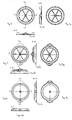
- Fig 1 is shown the cover viewed from above, while Fig 1a shows the section A-A from Fig 1; Fig 2 shows the cover with large flange viewed from below, Fig 2a shows the cover viewed from above, Fig 2b shows the section A-A from Fig 2 and Fig 2c shows the section B-B from Fig 2; on Fig 3 is shown the cover with flat surface viewed from below, Fig 3a shows this cover viewed from above, while Fig 3a shows section A-A from Fig 3 and Fig 3b shows section B-B from Fig 3; on Fig 4 is shown the cover with closing surface situated in the lower part of the cover, viewed from below, on Fig 4a is shown this cover viewed from above, Fig 4b shows section A-A from Fig 4 and Fig 4c shows section B-B from Fig 4; on Fig 5 is shown the cover with internal closing surface situated above flat surface of the ring,
- the cover is made from flexible plastic preferably "Multiflex" in form of profiled, flat closure with a ring (2) protruding above said flat closure and having outside a flange (8).
- the ring has in its inside a border (3) on its circumference of greater diameter, formed at an angle and shaped in form of a large arc.
- a lip (5) In the lower part of the ring there is a lip (5).
- a hole (4) in form of short stub tube covered at one side by a thin layer (9).
- the cover as in example 1 has a hole (4) in form of short stud tube with closure in form of thin layer of plastic (9) and a flange (8) having two holders in the shape of tongs (6) where one has an opening (11) and the second has a recess (6a).
- the closure (9) of the hole (4) is to be removed before introducing a safety funnel tube.
- the cover as in example 1 has two holes (4) in form of short stud tube (7), one destined for fastening a safety funnel tube and second enabling applying an additional equipment.
- the cover as in example 2 has a hole (4) situated outside cover axis
- the cover made of plastic has a ring (2) with a lip (5) along with a formed in its inside a border (3) on its external circumference.
- the ring surface (1) transfers into a flat closing surface , on which the hole (4) and ribs (7) are situated. (Fig 3)
- the cover made of plastic has a ring (2) with formed in its inside a border (3), a lip (5) and surface (1) formed on the bending of the internal vertical portion of the ring (2) thus making a cover with closing surface (10) at the height of the flange (8) situated outside the ring (2). (Fig 4)
- the cover as in example 1 has a surface (1) formed above surface of the ring (2) with a hole (4) protruding above this surface Fig 5
- the cover as in example 1 has a ring (2) transferring into concave surface.
Landscapes
- Health & Medical Sciences (AREA)
- Chemical & Material Sciences (AREA)
- Hematology (AREA)
- Mechanical Engineering (AREA)
- Analytical Chemistry (AREA)
- General Health & Medical Sciences (AREA)
- Engineering & Computer Science (AREA)
- Clinical Laboratory Science (AREA)
- Chemical Kinetics & Catalysis (AREA)
- Closures For Containers (AREA)
- Devices For Use In Laboratory Experiments (AREA)
- Catching Or Destruction (AREA)
- Apparatus Associated With Microorganisms And Enzymes (AREA)
Abstract
Cover according to the invention has on its circumference a ring (2) having inside a profiled border (3) and a cylindrical portion and a lip (5) situated in the proximity of the end of said cylindrical portion, and having, on cover closing surface (1) situated at the height selected according to the design, at least one hole (4), while, on the external side, having a flange (8) with an optional hole (11), and on the cover closing surface (1) having optional strengthening ribs (7) and/or other strengthening elements of any shape.
Cover has a hole (4) in the closing surface, which is situated in the cover axis or outside the axis, where the hole is being shaped in form of short stub pipe of height according to the design needs, and the closing surface (1) is in flat, convex or concave form.
Cover has the closing surface (1) covering the vessel opening which is situated at the height according to design needs.
Description
- The object of this invention is a cover for vessel with large opening , designed to close vessels like jars or glass balloons, in which fermentation process can be proceeded or various products can be stored.
- There are known various kinds of covers designed to close glass balloons or jars with large opening These covers are in the shape of large cork stoppers or hoods which are put upon vessel opening, where the opening has border, in cross section, is in shape of circular curve, created in the process of glass balloon or jar manufacture. The covers, which are to be put upon large openings of glass balloons or jars have gently curved inside borders, contacting the border of vessel opening at right angle, which do not seal the surface of contact. In order to increase the effectiveness of closing, additional seals are applied in the shape of rings, protrusions, bendings and so on.
- With the known covers for vessels with large openings safety funnel tubes cannot be applied in simple manner, thus making it difficult to proceed with fermentation process of the mass contained in the vessel, or it is difficult to introduce through the hole in the cover any additional substances or take samples for research or testing.
- Therefore the aim of the present invention is to provide a cover for the vessel with large opening, which enables to proceed with the processes inside the vessel or to store and preserve products.
- The cover for vessel with large opening, according to the present invention has on its circumference a ring having inside a profiled border and a cylindrical portion, and a lip situated in the proximity of the end of said cylindrical portion, and having at least one hole, on cover closing surface situated at the height selected according to the design, while, on the external side, having a flange with optional hole, and on the cover closing surface having optional strengthening ribs and/or other strengthening elements of any shape.
- The cover according to the invention has a hole in the closing surface situated preferably in the cover axis or outside the axis, while the hole is being shaped in form of short stub pipe of height according to the design needs.
- The cover according to the invention having optionally, on its external flange, at least one hole and , optionally, at least one holder of any form.
- The cover according to the invention having the closing surface, covering the vessel opening, in shape of flat, concave or convex form.
- The cover according to the invention having optionally a hole on its surface, closed optionally at one or both sides, as well as a ring having internal wall at angle from - 90° to +90° to its upper surface.
In the solution according to the invention the profiled internal surface of the ring and the lip situated at the end of the vertical portion of the ring fits into recess on the vessel under its flange resulting in tight closing of the vessel opening. - Profiled internal surface and the ring border of the cover create tight contact with the side surface of the vessel , thus tight closing of the vessel opening. Internally profiled border surface of the cover is optionally chamfered at an angle or stepped. Lip situated in internal end portion of the ring, upon putting the cover on the vessel opening, fills the cavity under the opening border resulting in the tightening of the cover on the vessel opening. Said lip acts as an O-ring thus sealing the vessel opening and at the same time, preventing sliding the cover from the vessel , while the profiled bending , situated inside , on the external circumference of the ring, creates tight contact with the vessel border, making it sealed.
- The surface, which closes the vessel opening, upon which a hole is optionally situated is flat or concave or convex. The shape of this surface does not affect the seal of the cover according to present invention.
- In solution according to the present invention upon the cover surface there is optionally a hole and/or a small stub tube , closed at one or both sides by a thin transparent plastic layer, which can be easily removed. In this hole a safety funnel tube is optionally inserted, enabling sealing of the vessel and enabling proceeding the fermentation process in this vessel. Optional ribs situated at one side or both sides of the cover surface strengthen the surface of the cover, which is advantageous especially in case when additional equipment is to be put upon the cover. The number and length of the ribs is to be selected according to the needs.
- The hole in the shape of stub tube with the height greater than the thickness of the layer of the closing surface, enables to fasten the safety funnel tube in vertical position. The flange of the cover situated on its border, protruding outside the cover contour is of shape and width according to the design needs and has optionally a holder of any shape. On the flange there is optionally a hole or recess of the shape according to the design needs or several holes of any shapes. On the flange holder or holders there are optionally recesses made of plastic facilitating the cover holding during its putting on or off. Upon the cover there are optionally situated various inscriptions.
- Cover according to present invention, incorporating the solutions enabling its tight contact with the vessel opening while preserving its easy putting on and off on the vessel and enabling assembling a safety funnel tube is of various external shape. In the embodiments of the cover, on the cover closing surface there are optionally additional holes serving for putting on, or inserting into the vessel, additional equipment. The hole situated on the closing surface of the cover is positioned on a height selected according to the needs.
- The solution according to this invention is shown in exemplary embodiments on drawings Fig 1 to Fig 9. On Fig 1 is shown the cover viewed from above, while Fig 1a shows the section A-A from Fig 1; Fig 2 shows the cover with large flange viewed from below, Fig 2a shows the cover viewed from above, Fig 2b shows the section A-A from Fig 2 and Fig 2c shows the section B-B from Fig 2; on Fig 3 is shown the cover with flat surface viewed from below, Fig 3a shows this cover viewed from above, while Fig 3a shows section A-A from Fig 3 and Fig 3b shows section B-B from Fig 3; on Fig 4 is shown the cover with closing surface situated in the lower part of the cover, viewed from below, on Fig 4a is shown this cover viewed from above, Fig 4b shows section A-A from Fig 4 and Fig 4c shows section B-B from Fig 4; on Fig 5 is shown the cover with internal closing surface situated above flat surface of the ring, viewed from below, Fig 5a shows this cover viewed from above, Fig 5b shows section A-A from Fig 5 and Fig 5c shows section B-B from Fig 5; on Fig 6 is shown the cover with concave closing surface viewed from below, Fig 6a shows this cover viewed from above, Fig 6b shows section A-A from Fig 6 and Fig 6c shows section B-B from Fig 6; on Fig 7 is shown the cover with hole situated outside cover axis viewed from below, Fig 7a shows this cover viewed from above, Fig 7b shows section A-A from Fig 7 and Fig 7c shows section B-B from Fig 7; on Fig 8 is shown the cover with internal closing surface situated below flat surface of the ring, viewed from below, Fig 8a shows this cover viewed from above, Fig 8b shows section A-A from Fig 8 and Fig 8c shows section B-B from Fig 8; on Fig 9 is shown the cover with closing surface without strengthening viewed from below, Fig 9a shows this cover viewed from above, Fig 9b shows section A-A from Fig 9 and Fig 9c shows section B-B from Fig 9.
- The cover is made from flexible plastic preferably "Multiflex" in form of profiled, flat closure with a ring (2) protruding above said flat closure and having outside a flange (8).The ring has in its inside a border (3) on its circumference of greater diameter, formed at an angle and shaped in form of a large arc. In the lower part of the ring there is a lip (5). In the cover axis there is a hole (4) in form of short stub tube covered at one side by a thin layer (9). On the external flange (8) there is a hole (11) and a holder (6) with a recess (6a) on its surface.
- The cover as in example 1 has a hole (4) in form of short stud tube with closure in form of thin layer of plastic (9) and a flange (8) having two holders in the shape of tongs (6) where one has an opening (11) and the second has a recess (6a).. The closure (9) of the hole (4) is to be removed before introducing a safety funnel tube. On the flat surface (1) there are ribs (7) stiffening the closing surface of the cover.
- The cover as in example 1 has two holes (4) in form of short stud tube (7), one destined for fastening a safety funnel tube and second enabling applying an additional equipment.
- The cover as in example 2 has a hole (4) situated outside cover axis
- The cover made of plastic has a ring (2) with a lip (5) along with a formed in its inside a border (3) on its external circumference. The ring surface (1) transfers into a flat closing surface , on which the hole (4) and ribs (7) are situated. (Fig 3)
- The cover made of plastic has a ring (2) with formed in its inside a border (3), a lip (5) and surface (1) formed on the bending of the internal vertical portion of the ring (2) thus making a cover with closing surface (10) at the height of the flange (8) situated outside the ring (2). (Fig 4)
- The cover as in example 1 has a surface (1) formed above surface of the ring (2) with a hole (4) protruding above this surface Fig 5
- The cover as in example 1 has a ring (2) transferring into concave surface. Fig 6
Claims (8)
- Cover for vessel with large opening in form of a short cylinder, closed at one side by a surface, characterized by a fact, that has on its circumference a ring (2) having inside a profiled border (3) and a cylindrical portion and a lip (5) situated in the proximity of the end of said cylindrical portion, and having, on the cover closing surface (1) situated at the height selected according to the design, at least one hole (4) while, on the external side having a flange (8) with optional hole (11), and having, on the surface (1), optional strengthening ribs (7) and/or other strengthening elements.
- Cover according to claim 1, characterized by the fact, that the hole (4) is situated in the cover axis or outside the axis , while the hole being in the shape of short stub pipe of height according to the design needs.
- Cover according to claim 1, characterized by the fact, that the closing surface (1), which closes the vessel opening, is in shape flat, concave or convex form.
- Cover according to claim 1, characterized by the fact, that the flange (8) has optionally a holder (6).
- Cover according to claim 1, characterized by the fact, that on surface (1) has a hole (4) optionally covered at one or both sides by a thin layer (9).
- Cover according to claim 1, characterized by the fact, that the flange (8) has at least one hole (11).
- Cover according to claim 1, characterized by the fact, that the closing surface (1) covering the vessel opening is situated at the height according to design needs.
- Cover according to claim 1, characterized by the fact, that the ring (2) optionally has internal wall (12) at an angle from -90° to +90° to its upper surface (13).
Priority Applications (4)
| Application Number | Priority Date | Filing Date | Title |
|---|---|---|---|
| DE602005020154T DE602005020154D1 (en) | 2005-11-18 | 2005-11-18 | Lid for containers with a large opening |
| AT05460032T ATE461744T1 (en) | 2005-11-18 | 2005-11-18 | LID FOR LARGE OPENING CONTAINER |
| PL05460032T PL1787721T3 (en) | 2005-11-18 | 2005-11-18 | Cover for vessel with large opening |
| EP05460032A EP1787721B1 (en) | 2005-11-18 | 2005-11-18 | Cover for vessel with large opening |
Applications Claiming Priority (1)
| Application Number | Priority Date | Filing Date | Title |
|---|---|---|---|
| EP05460032A EP1787721B1 (en) | 2005-11-18 | 2005-11-18 | Cover for vessel with large opening |
Publications (2)
| Publication Number | Publication Date |
|---|---|
| EP1787721A1 true EP1787721A1 (en) | 2007-05-23 |
| EP1787721B1 EP1787721B1 (en) | 2010-03-24 |
Family
ID=36001146
Family Applications (1)
| Application Number | Title | Priority Date | Filing Date |
|---|---|---|---|
| EP05460032A Expired - Lifetime EP1787721B1 (en) | 2005-11-18 | 2005-11-18 | Cover for vessel with large opening |
Country Status (4)
| Country | Link |
|---|---|
| EP (1) | EP1787721B1 (en) |
| AT (1) | ATE461744T1 (en) |
| DE (1) | DE602005020154D1 (en) |
| PL (1) | PL1787721T3 (en) |
Citations (3)
| Publication number | Priority date | Publication date | Assignee | Title |
|---|---|---|---|---|
| DE3343055A1 (en) * | 1983-11-29 | 1984-04-05 | Konrad 5210 Troisdorf Porombka | Lid for preserving jars |
| US4545498A (en) * | 1983-04-08 | 1985-10-08 | Asepta Ag Wil/Sg | Container with lid for effervescent products |
| US4713219A (en) * | 1984-01-24 | 1987-12-15 | Eppendorf Geratebau Netheler & Hinz Gmbh | Plastic reaction vessel |
-
2005
- 2005-11-18 DE DE602005020154T patent/DE602005020154D1/en not_active Expired - Lifetime
- 2005-11-18 AT AT05460032T patent/ATE461744T1/en not_active IP Right Cessation
- 2005-11-18 EP EP05460032A patent/EP1787721B1/en not_active Expired - Lifetime
- 2005-11-18 PL PL05460032T patent/PL1787721T3/en unknown
Patent Citations (3)
| Publication number | Priority date | Publication date | Assignee | Title |
|---|---|---|---|---|
| US4545498A (en) * | 1983-04-08 | 1985-10-08 | Asepta Ag Wil/Sg | Container with lid for effervescent products |
| DE3343055A1 (en) * | 1983-11-29 | 1984-04-05 | Konrad 5210 Troisdorf Porombka | Lid for preserving jars |
| US4713219A (en) * | 1984-01-24 | 1987-12-15 | Eppendorf Geratebau Netheler & Hinz Gmbh | Plastic reaction vessel |
Also Published As
| Publication number | Publication date |
|---|---|
| PL1787721T3 (en) | 2010-08-31 |
| EP1787721B1 (en) | 2010-03-24 |
| DE602005020154D1 (en) | 2010-05-06 |
| ATE461744T1 (en) | 2010-04-15 |
Similar Documents
| Publication | Publication Date | Title |
|---|---|---|
| EP1069049A2 (en) | Cap for aluminum and/or steel bottles | |
| US20060016778A1 (en) | Bottle lid | |
| EP2517791A1 (en) | Sample tube with improved lid | |
| US20030052074A1 (en) | Closure for container for holding biological samples | |
| US4192428A (en) | Bottle cap | |
| EP1728727A3 (en) | Sealing mechanism for container opening | |
| US8616399B2 (en) | Reclosable container lid having a cover member | |
| WO1995034381A3 (en) | Perforable cap for a biological specimen container | |
| ES2225073T3 (en) | DEVICE FOR CLOSING BOTTLES CONTAINING LIQUIDS UNDER PRESSURE, ESPECIALLY SHAMPAN OR SIMILAR PRODUCTS. | |
| US3371811A (en) | Container closure | |
| EP1787721A1 (en) | Cover for vessel with large opening | |
| US5702018A (en) | Positive seal fermentation lock for wine barrels | |
| US20080296249A1 (en) | Combination bottle and bottle cap opener | |
| JPS6229403Y2 (en) | ||
| KR101251325B1 (en) | Cap for sealed container | |
| MXNL05000009A (en) | Metallic cap closure having water repelling properties and method of fabricating the same. | |
| TWM610131U (en) | Sealing structure for preservation container and preservation container | |
| CN101959764A (en) | Closures for beverage containers | |
| EP3458189A1 (en) | Tank closing unit | |
| US2663455A (en) | Can | |
| US9540150B1 (en) | Stopper with sheath for a container | |
| KR200419790Y1 (en) | Airtight containers | |
| KR910000121Y1 (en) | Bootle cap | |
| RU54906U1 (en) | TIP OF ELASTIC CONTAINER | |
| AU2006251211B2 (en) | Tin lid with guide posts for a container |
Legal Events
| Date | Code | Title | Description |
|---|---|---|---|
| PUAI | Public reference made under article 153(3) epc to a published international application that has entered the european phase |
Free format text: ORIGINAL CODE: 0009012 |
|
| AK | Designated contracting states |
Kind code of ref document: A1 Designated state(s): AT BE BG CH CY CZ DE DK EE ES FI FR GB GR HU IE IS IT LI LT LU LV MC NL PL PT RO SE SI SK TR |
|
| AX | Request for extension of the european patent |
Extension state: AL BA HR MK YU |
|
| 17P | Request for examination filed |
Effective date: 20070719 |
|
| 17Q | First examination report despatched |
Effective date: 20070903 |
|
| AKX | Designation fees paid |
Designated state(s): AT BE BG CH CY CZ DE DK EE ES FI FR GB GR HU IE IS IT LI LT LU LV MC NL PL PT RO SE SI SK TR |
|
| GRAP | Despatch of communication of intention to grant a patent |
Free format text: ORIGINAL CODE: EPIDOSNIGR1 |
|
| GRAS | Grant fee paid |
Free format text: ORIGINAL CODE: EPIDOSNIGR3 |
|
| GRAA | (expected) grant |
Free format text: ORIGINAL CODE: 0009210 |
|
| AK | Designated contracting states |
Kind code of ref document: B1 Designated state(s): AT BE BG CH CY CZ DE DK EE ES FI FR GB GR HU IE IS IT LI LT LU LV MC NL PL PT RO SE SI SK TR |
|
| REG | Reference to a national code |
Ref country code: GB Ref legal event code: FG4D |
|
| REG | Reference to a national code |
Ref country code: CH Ref legal event code: EP |
|
| REG | Reference to a national code |
Ref country code: IE Ref legal event code: FG4D |
|
| REF | Corresponds to: |
Ref document number: 602005020154 Country of ref document: DE Date of ref document: 20100506 Kind code of ref document: P |
|
| REG | Reference to a national code |
Ref country code: NL Ref legal event code: VDEP Effective date: 20100324 |
|
| PG25 | Lapsed in a contracting state [announced via postgrant information from national office to epo] |
Ref country code: LT Free format text: LAPSE BECAUSE OF FAILURE TO SUBMIT A TRANSLATION OF THE DESCRIPTION OR TO PAY THE FEE WITHIN THE PRESCRIBED TIME-LIMIT Effective date: 20100324 |
|
| LTIE | Lt: invalidation of european patent or patent extension |
Effective date: 20100324 |
|
| PG25 | Lapsed in a contracting state [announced via postgrant information from national office to epo] |
Ref country code: AT Free format text: LAPSE BECAUSE OF FAILURE TO SUBMIT A TRANSLATION OF THE DESCRIPTION OR TO PAY THE FEE WITHIN THE PRESCRIBED TIME-LIMIT Effective date: 20100324 Ref country code: FI Free format text: LAPSE BECAUSE OF FAILURE TO SUBMIT A TRANSLATION OF THE DESCRIPTION OR TO PAY THE FEE WITHIN THE PRESCRIBED TIME-LIMIT Effective date: 20100324 Ref country code: LV Free format text: LAPSE BECAUSE OF FAILURE TO SUBMIT A TRANSLATION OF THE DESCRIPTION OR TO PAY THE FEE WITHIN THE PRESCRIBED TIME-LIMIT Effective date: 20100324 Ref country code: SI Free format text: LAPSE BECAUSE OF FAILURE TO SUBMIT A TRANSLATION OF THE DESCRIPTION OR TO PAY THE FEE WITHIN THE PRESCRIBED TIME-LIMIT Effective date: 20100324 |
|
| REG | Reference to a national code |
Ref country code: PL Ref legal event code: T3 |
|
| PG25 | Lapsed in a contracting state [announced via postgrant information from national office to epo] |
Ref country code: GR Free format text: LAPSE BECAUSE OF FAILURE TO SUBMIT A TRANSLATION OF THE DESCRIPTION OR TO PAY THE FEE WITHIN THE PRESCRIBED TIME-LIMIT Effective date: 20100625 Ref country code: NL Free format text: LAPSE BECAUSE OF FAILURE TO SUBMIT A TRANSLATION OF THE DESCRIPTION OR TO PAY THE FEE WITHIN THE PRESCRIBED TIME-LIMIT Effective date: 20100324 Ref country code: RO Free format text: LAPSE BECAUSE OF FAILURE TO SUBMIT A TRANSLATION OF THE DESCRIPTION OR TO PAY THE FEE WITHIN THE PRESCRIBED TIME-LIMIT Effective date: 20100324 Ref country code: SE Free format text: LAPSE BECAUSE OF FAILURE TO SUBMIT A TRANSLATION OF THE DESCRIPTION OR TO PAY THE FEE WITHIN THE PRESCRIBED TIME-LIMIT Effective date: 20100324 Ref country code: BE Free format text: LAPSE BECAUSE OF FAILURE TO SUBMIT A TRANSLATION OF THE DESCRIPTION OR TO PAY THE FEE WITHIN THE PRESCRIBED TIME-LIMIT Effective date: 20100324 Ref country code: EE Free format text: LAPSE BECAUSE OF FAILURE TO SUBMIT A TRANSLATION OF THE DESCRIPTION OR TO PAY THE FEE WITHIN THE PRESCRIBED TIME-LIMIT Effective date: 20100324 Ref country code: ES Free format text: LAPSE BECAUSE OF FAILURE TO SUBMIT A TRANSLATION OF THE DESCRIPTION OR TO PAY THE FEE WITHIN THE PRESCRIBED TIME-LIMIT Effective date: 20100705 |
|
| PG25 | Lapsed in a contracting state [announced via postgrant information from national office to epo] |
Ref country code: SK Free format text: LAPSE BECAUSE OF FAILURE TO SUBMIT A TRANSLATION OF THE DESCRIPTION OR TO PAY THE FEE WITHIN THE PRESCRIBED TIME-LIMIT Effective date: 20100324 Ref country code: CZ Free format text: LAPSE BECAUSE OF FAILURE TO SUBMIT A TRANSLATION OF THE DESCRIPTION OR TO PAY THE FEE WITHIN THE PRESCRIBED TIME-LIMIT Effective date: 20100324 Ref country code: BG Free format text: LAPSE BECAUSE OF FAILURE TO SUBMIT A TRANSLATION OF THE DESCRIPTION OR TO PAY THE FEE WITHIN THE PRESCRIBED TIME-LIMIT Effective date: 20100624 Ref country code: IS Free format text: LAPSE BECAUSE OF FAILURE TO SUBMIT A TRANSLATION OF THE DESCRIPTION OR TO PAY THE FEE WITHIN THE PRESCRIBED TIME-LIMIT Effective date: 20100724 |
|
| PLBE | No opposition filed within time limit |
Free format text: ORIGINAL CODE: 0009261 |
|
| STAA | Information on the status of an ep patent application or granted ep patent |
Free format text: STATUS: NO OPPOSITION FILED WITHIN TIME LIMIT |
|
| PG25 | Lapsed in a contracting state [announced via postgrant information from national office to epo] |
Ref country code: DK Free format text: LAPSE BECAUSE OF FAILURE TO SUBMIT A TRANSLATION OF THE DESCRIPTION OR TO PAY THE FEE WITHIN THE PRESCRIBED TIME-LIMIT Effective date: 20100324 Ref country code: PT Free format text: LAPSE BECAUSE OF FAILURE TO SUBMIT A TRANSLATION OF THE DESCRIPTION OR TO PAY THE FEE WITHIN THE PRESCRIBED TIME-LIMIT Effective date: 20100726 |
|
| 26N | No opposition filed |
Effective date: 20101228 |
|
| PG25 | Lapsed in a contracting state [announced via postgrant information from national office to epo] |
Ref country code: IT Free format text: LAPSE BECAUSE OF FAILURE TO SUBMIT A TRANSLATION OF THE DESCRIPTION OR TO PAY THE FEE WITHIN THE PRESCRIBED TIME-LIMIT Effective date: 20100324 |
|
| PG25 | Lapsed in a contracting state [announced via postgrant information from national office to epo] |
Ref country code: MC Free format text: LAPSE BECAUSE OF NON-PAYMENT OF DUE FEES Effective date: 20101130 |
|
| REG | Reference to a national code |
Ref country code: CH Ref legal event code: PL |
|
| GBPC | Gb: european patent ceased through non-payment of renewal fee |
Effective date: 20101118 |
|
| PG25 | Lapsed in a contracting state [announced via postgrant information from national office to epo] |
Ref country code: CH Free format text: LAPSE BECAUSE OF NON-PAYMENT OF DUE FEES Effective date: 20101130 Ref country code: LI Free format text: LAPSE BECAUSE OF NON-PAYMENT OF DUE FEES Effective date: 20101130 |
|
| REG | Reference to a national code |
Ref country code: FR Ref legal event code: ST Effective date: 20110801 |
|
| REG | Reference to a national code |
Ref country code: DE Ref legal event code: R119 Ref document number: 602005020154 Country of ref document: DE Effective date: 20110601 Ref country code: DE Ref legal event code: R119 Ref document number: 602005020154 Country of ref document: DE Effective date: 20110531 |
|
| PG25 | Lapsed in a contracting state [announced via postgrant information from national office to epo] |
Ref country code: IE Free format text: LAPSE BECAUSE OF NON-PAYMENT OF DUE FEES Effective date: 20101118 Ref country code: FR Free format text: LAPSE BECAUSE OF NON-PAYMENT OF DUE FEES Effective date: 20101130 |
|
| PG25 | Lapsed in a contracting state [announced via postgrant information from national office to epo] |
Ref country code: GB Free format text: LAPSE BECAUSE OF NON-PAYMENT OF DUE FEES Effective date: 20101118 |
|
| PG25 | Lapsed in a contracting state [announced via postgrant information from national office to epo] |
Ref country code: CY Free format text: LAPSE BECAUSE OF FAILURE TO SUBMIT A TRANSLATION OF THE DESCRIPTION OR TO PAY THE FEE WITHIN THE PRESCRIBED TIME-LIMIT Effective date: 20100324 |
|
| PG25 | Lapsed in a contracting state [announced via postgrant information from national office to epo] |
Ref country code: LU Free format text: LAPSE BECAUSE OF NON-PAYMENT OF DUE FEES Effective date: 20101118 Ref country code: HU Free format text: LAPSE BECAUSE OF FAILURE TO SUBMIT A TRANSLATION OF THE DESCRIPTION OR TO PAY THE FEE WITHIN THE PRESCRIBED TIME-LIMIT Effective date: 20100925 |
|
| PG25 | Lapsed in a contracting state [announced via postgrant information from national office to epo] |
Ref country code: TR Free format text: LAPSE BECAUSE OF FAILURE TO SUBMIT A TRANSLATION OF THE DESCRIPTION OR TO PAY THE FEE WITHIN THE PRESCRIBED TIME-LIMIT Effective date: 20100324 |
|
| PG25 | Lapsed in a contracting state [announced via postgrant information from national office to epo] |
Ref country code: DE Free format text: LAPSE BECAUSE OF NON-PAYMENT OF DUE FEES Effective date: 20110531 |
|
| PGFP | Annual fee paid to national office [announced via postgrant information from national office to epo] |
Ref country code: PL Payment date: 20181015 Year of fee payment: 14 |
|
| PG25 | Lapsed in a contracting state [announced via postgrant information from national office to epo] |
Ref country code: PL Free format text: LAPSE BECAUSE OF NON-PAYMENT OF DUE FEES Effective date: 20191118 |