EP1786962B1 - Uses of auxetic fibres - Google Patents
Uses of auxetic fibres Download PDFInfo
- Publication number
- EP1786962B1 EP1786962B1 EP20050773180 EP05773180A EP1786962B1 EP 1786962 B1 EP1786962 B1 EP 1786962B1 EP 20050773180 EP20050773180 EP 20050773180 EP 05773180 A EP05773180 A EP 05773180A EP 1786962 B1 EP1786962 B1 EP 1786962B1
- Authority
- EP
- European Patent Office
- Prior art keywords
- component
- auxetic
- fabric
- porous material
- fibres
- Prior art date
- Legal status (The legal status is an assumption and is not a legal conclusion. Google has not performed a legal analysis and makes no representation as to the accuracy of the status listed.)
- Expired - Lifetime
Links
Images


Classifications
-
- B—PERFORMING OPERATIONS; TRANSPORTING
- B01—PHYSICAL OR CHEMICAL PROCESSES OR APPARATUS IN GENERAL
- B01D—SEPARATION
- B01D39/00—Filtering material for liquid or gaseous fluids
- B01D39/08—Filter cloth, i.e. woven, knitted or interlaced material
-
- D—TEXTILES; PAPER
- D02—YARNS; MECHANICAL FINISHING OF YARNS OR ROPES; WARPING OR BEAMING
- D02G—CRIMPING OR CURLING FIBRES, FILAMENTS, THREADS, OR YARNS; YARNS OR THREADS
- D02G3/00—Yarns or threads, e.g. fancy yarns; Processes or apparatus for the production thereof, not otherwise provided for
- D02G3/22—Yarns or threads characterised by constructional features, e.g. blending, filament/fibre
- D02G3/32—Elastic yarns or threads ; Production of plied or cored yarns, one of which is elastic
-
- Y—GENERAL TAGGING OF NEW TECHNOLOGICAL DEVELOPMENTS; GENERAL TAGGING OF CROSS-SECTIONAL TECHNOLOGIES SPANNING OVER SEVERAL SECTIONS OF THE IPC; TECHNICAL SUBJECTS COVERED BY FORMER USPC CROSS-REFERENCE ART COLLECTIONS [XRACs] AND DIGESTS
- Y10—TECHNICAL SUBJECTS COVERED BY FORMER USPC
- Y10T—TECHNICAL SUBJECTS COVERED BY FORMER US CLASSIFICATION
- Y10T428/00—Stock material or miscellaneous articles
- Y10T428/13—Hollow or container type article [e.g., tube, vase, etc.]
- Y10T428/1352—Polymer or resin containing [i.e., natural or synthetic]
- Y10T428/1362—Textile, fabric, cloth, or pile containing [e.g., web, net, woven, knitted, mesh, nonwoven, matted, etc.]
-
- Y—GENERAL TAGGING OF NEW TECHNOLOGICAL DEVELOPMENTS; GENERAL TAGGING OF CROSS-SECTIONAL TECHNOLOGIES SPANNING OVER SEVERAL SECTIONS OF THE IPC; TECHNICAL SUBJECTS COVERED BY FORMER USPC CROSS-REFERENCE ART COLLECTIONS [XRACs] AND DIGESTS
- Y10—TECHNICAL SUBJECTS COVERED BY FORMER USPC
- Y10T—TECHNICAL SUBJECTS COVERED BY FORMER US CLASSIFICATION
- Y10T428/00—Stock material or miscellaneous articles
- Y10T428/249921—Web or sheet containing structurally defined element or component
- Y10T428/249924—Noninterengaged fiber-containing paper-free web or sheet which is not of specified porosity
- Y10T428/249933—Fiber embedded in or on the surface of a natural or synthetic rubber matrix
- Y10T428/249938—Composite or conjugate fiber [e.g., fiber contains more than one chemically different material in monofilament or multifilament form, etc.]
-
- Y—GENERAL TAGGING OF NEW TECHNOLOGICAL DEVELOPMENTS; GENERAL TAGGING OF CROSS-SECTIONAL TECHNOLOGIES SPANNING OVER SEVERAL SECTIONS OF THE IPC; TECHNICAL SUBJECTS COVERED BY FORMER USPC CROSS-REFERENCE ART COLLECTIONS [XRACs] AND DIGESTS
- Y10—TECHNICAL SUBJECTS COVERED BY FORMER USPC
- Y10T—TECHNICAL SUBJECTS COVERED BY FORMER US CLASSIFICATION
- Y10T428/00—Stock material or miscellaneous articles
- Y10T428/249921—Web or sheet containing structurally defined element or component
- Y10T428/249924—Noninterengaged fiber-containing paper-free web or sheet which is not of specified porosity
- Y10T428/249933—Fiber embedded in or on the surface of a natural or synthetic rubber matrix
- Y10T428/249939—Two or more layers
-
- Y—GENERAL TAGGING OF NEW TECHNOLOGICAL DEVELOPMENTS; GENERAL TAGGING OF CROSS-SECTIONAL TECHNOLOGIES SPANNING OVER SEVERAL SECTIONS OF THE IPC; TECHNICAL SUBJECTS COVERED BY FORMER USPC CROSS-REFERENCE ART COLLECTIONS [XRACs] AND DIGESTS
- Y10—TECHNICAL SUBJECTS COVERED BY FORMER USPC
- Y10T—TECHNICAL SUBJECTS COVERED BY FORMER US CLASSIFICATION
- Y10T442/00—Fabric [woven, knitted, or nonwoven textile or cloth, etc.]
- Y10T442/30—Woven fabric [i.e., woven strand or strip material]
-
- Y—GENERAL TAGGING OF NEW TECHNOLOGICAL DEVELOPMENTS; GENERAL TAGGING OF CROSS-SECTIONAL TECHNOLOGIES SPANNING OVER SEVERAL SECTIONS OF THE IPC; TECHNICAL SUBJECTS COVERED BY FORMER USPC CROSS-REFERENCE ART COLLECTIONS [XRACs] AND DIGESTS
- Y10—TECHNICAL SUBJECTS COVERED BY FORMER USPC
- Y10T—TECHNICAL SUBJECTS COVERED BY FORMER US CLASSIFICATION
- Y10T442/00—Fabric [woven, knitted, or nonwoven textile or cloth, etc.]
- Y10T442/60—Nonwoven fabric [i.e., nonwoven strand or fiber material]
Definitions
- This invention relates to uses of auxetic fibres, in particular to methods of using a porous material comprising a plurality of interconnected auxetic fibres.
- auxetic materials are materials that have a negative or effectively negative Poisson's ratio.
- auxetic materials possess the property that under a tensile load the material expands perpendicularly to the axis along which the tensile load is applied. In other words, auxetic materials expand as they are stretched.
- materials are also auxetic if a compressive load applied along an axis results in a reduction in the dimension of the material along an axis perpendicular to the axis along which the compressive load is applied.
- Most materials exhibit a positive Poisson's ratio, this ratio being defined by the ratio of the contractile transverse strain relative to the tensile longitudinal strain.
- Prior art auxetic materials can essentially be divided into two categories.
- One category comprises honeycomb like polymeric materials, and the other category comprises materials formed by particles linked by fibrils, such as materials described in the International Publication WO 00/53830 .
- both of these categories of auxetic materials have signficant drawbacks preventing commercialisation on an industrial scale.
- problems in producing such auxetic materials reliably and cost-effectively using techniques which are suitable for commercialisation.
- structural characteristics of these prior art auxetic materials made them unsuitable for numerous applications.
- the inventor of the present application has developed a new category of auxetic materials which are described in a co-pending application. The present application relates to new and useful methods of using such auxetic materials.
- the porous material comprises sheet material.
- the porous material comprises a fabric, which is typically, but not necessarily, a sheet material. It is advantageous that sheet material and fabrics can be readily produced using auxetic fibres of the type disclosed herein. Sheet materials and/or fabrics are useful in a range of application areas, such as textiles, which prior art auxetic materials of the type described above have little or no practical utility. Fabrics of the present may be woven, knitted, non-woven, felted, braided, netted or produced by any other suitable technique.
- the porous material may comprise three or more interconnected auxetic fibres. It is preferred that the auxetic fibres demonstrate auxetic properties over a substantial portion of the range of fibre lengths over which it is possible to stretch or compress the fibre without failure of the fibre.
- the auxetic fibres comprise a first component and a second component.
- the modulus of elasticity of the first component may be greater than the modulus of elasticity of the second component.
- the first component and the second component extend generally longitudinally relative to an axis, and variation in a tensile or compressive load applied to the first component causes the radial position of the second component relative to the axis to vary.
- At least one of the first component and the second component is helically wrapped around the other component. It will become apparent to the skilled reader that, with a given auxetic fibre of this type, at some applied strains both the first and second components may be helically wrapped around the other component, but at other (higher) applied strains the first component may substantially straighten so as to no longer be helically wrapped around the second component. In principle, the second component might be substantially straight at low applied strain.
- the pores may be formed between adjacent auxetic fibres, wherein helices formed by the first components of the adjacent auxetic fibres are in-phase but of opposite handidness and helices formed by the second components of the adjacent auxetic fibres are in-phase but of opposite handidness. It will be appreciated by the skilled reader that, since it is possible that at some applied strains the first or second component might be substantially straight, it is not a necessary condition that helices are formed by both the first components, and the second components.
- the auxetic fibres may comprise a first component and a second component, the first component and the second component extending generally longitudinally relative to an axis, the first component being wrapped around the second component through one or more turns, the one or more turns being spaced longitudinally relative to the axis, variation in the tensile load on the first component causing the radial position of the second component relative to the axis to vary.
- the auxetic fibres may comprise a first component and a second component, the first component and second component extending generally longitudinally relative to an axis, the first component being wrapped around the second component through one or more turns, the first component having a higher modulus of elasticity than the second component, variation in the tensile or compressive load on the first component causing the radial position of the second component relative to the axis to vary.
- the auxetic fibres may comprise a first component and a second component, the first component and second component extending generally longitudinally relative to an axis, the first component being wrapped around the second component in a helical manner, variation in the tensile or compressive load on the first component causing variation in the diameter of the helix the first component follows, the variation in the diameter of the helix of the first component causing the second component to take on the form of a helix and/or causing the diameter of the helix of the second component to vary, the diameter of the second component helix increasing as the first component helix decreased in diameter, the diameter of the second component helix decreasing as the first component helix increases in diameter.
- the auxetic fibres and/or the porous material may have a negative Poisson's ratio. Fibres and/or materials having a Poisson's ratio of between 0 and -35 are preferred.
- the Poisson ratio of a fibre is in part dependent on the pitch of the first component. A steep pitch gives rise to a relatively low auxetic effect over a relatively large strain range whereas a shallow pitch gives rise to a relatively large auxetic effect over a relatively narrow strain range. In general, more negative Poisson's ratios are preferred.
- the first component may be a fibre, rod or hollow tube particularly of a relatively high modulus material.
- the first component may be formed of carbon fibre, glass fibre, polyaramids (e.g. Kevlar TM), polyamides (e.g. nylon), polyesters, polyalkalenes, polyethyleneterepthalate (PET), metal wire, cotton or other material.
- the materials from which the first component is formed may be natural or man made, inorganic or organic.
- the first component may be sealed with a cured film, for example a cured siloxane film. In the event that the first component is a hollow tube, the tube may contain additional materials.
- the second component may be a fibre, rod or hollow tube, particularly consisting of an intermediate or a low modulus material.
- the material is preferably capable of deformation without fracture.
- the second component may be formed of siloxane, liquid silicone rubber, natural rubber, nitrile rubber or other elastomeric material whether natural or man-made.
- the second component does not need to be elastomeric.
- a polyamide such as nylon can be used advantageously, particularly in combination with a polyaramid as the first component.
- the first component may have a diameter that is between 0.01 and 1 times the diameter of the second component.
- the first component mayhave a cross-sectional area that is between 0.001 and 1 times the cross-sectional area of the second component.
- the first component and/or second component may be formed of a continuous material.
- the first component and/or second component are elongate.
- the first component and/or second component may be at least a hundred times as long as their maximum cross-sectional dimension or extent.
- the wrapping of the first component around the second component may be provided in the form of a covering or winding.
- the wrapping of the first component around the second component may be in the form of a spiral or helix.
- the spiral or helix may have a constant pitch along the second component. The pitch may be between zero degrees and ninety degrees relative to the axis.
- the second component may be linear with the first component wrapped around it.
- the second component may also be wrapped around the first component.
- the second component may be in the form of a spiral or helix.
- the pitch of the first component spiral or helix may be the same as the pitch of the second component spiral or helix.
- the porous material may comprise repeat units of two or more auxetic fibres.
- the auxetic fibres in the repeat units may be arranged around a core component. However, it is preferred that a core component is not employed.
- the pulse of air may be associated with blast energy from an explosion, or may be high pressure wind.
- the porous material may comprise a plurality of layers, each layer comprising a plurality of interconnected auxetic fibres. At least two layers may have different physical characteristics thereby improving the dispersion of the high air pressure.
- the physical characteristic may be pore size, fibre winding angle, fibre diameter or fibre type.
- FIG 1 shows an auxetic fibre which may be utilised in the production of porous materials according to the invention.
- the auxetic fibre 10 comprises a first component 12 and a second component 14.
- the first component 12 is wrapped around the periphery of the second component 14 forming a helix.
- the wrapping of the first component 12 around the second component 14 causes a deformation of the second component 14 from a generally linear configuration to a helical configuration.
- the first component is desirably formed from a material having a high modulus of elasticity, such as carbon fibre, Kevlar (RTM), glass fibre, wire, polyamides, polyesters, polyalkalenes, BET, or a natural fibre such as cotton.
- RTM Kevlar
- the second component is preferably formed from a material of lower modulus of elasticity than the first component.
- suitable materials include siloxane, silicone rubber, natural rubber, nitrile rubber or polyamides such as nylon. It should be noted that it is possible for the second component to be formed from a material of relatively high modulus of elasticity, such as nylon, provided it is used in combination with a first component formed from a material of higher modulus of elasticity.
- nylon can be used in combination with a suitable first component such as a polyaramid.
- FIG 2 shows a pair of auxetic fibres 10 of the type described above with reference to Figure 1 .
- the pair of auxetic fibres 10a, 10b are dispersed so as to form a plurality of pores 20.
- the helices formed by the first components 12a, 12b of the auxetic fibres 10a, 10b are in phase, but form helices of opposite handidness. Owing to the helical configuration imposed upon the second components 14a, 14b by the first components 12a, 12b, a similar relationship exists between the second components 14a, 14b, i.e. the helices formed by the second components 14a, 14b are in phase but are of opposite handidness.
- the diameter of the helices formed by the second components 14a, 14b increases.
- one second component 14a is displaced to higher values of y whereas the other second component 14b is displaced to lower values of y.
- the effect of the displacements caused by the application of a tensile load is to increase the size of the pores 20.
- the present invention utilizes this phenomenon to advantageously control pore size in a variety of porous materials fabricated from auxetic fibres.
- auxetic fibres of the type described give reference to Figure 1 are preferred. However, it is possible to utilise other auxetic fibres.
- an auxetic fibre can be produced which consists of a plurality of auxetic fibres of the type shown in Figure 1 arranged around a core component.
- an auxetic fibre might be produced utilising a pair auxetic fibres of the type shown in Figure 2 with a core component disposed between the auxetic fibres.
- the core component would extend generally longitudinally along the x axis.
- the overall structure could be regarded as an auxetic fibre for use in producing a porous material.
- the present invention anticipates that further auxetic fibres will be developed, and that such auxetic fibres can be usefully incorporated into the present invention in a straightforward manner using the principles described herein.
- FIGs 4 and 5 depict a porous material 40.
- the porous material 40 comprises an array of pairs of adjacent auxetic fibres of the type shown in Figures 2 and 3 .
- the array of pairs of auxetic yarns forms a flat sheet fabric.
- the fabric shown in Figures 4 and 5 is a woven fabric, and for reasons of presentational simplicity, these Figures depict only the warp fibres. In other words, the weft threads are not shown in Figures 4 and 5 , although the skilled reader will appreciate thatweft threads will be present in the woven fabric so as to interconnect warp fibres.
- Theweft fibres may be auxetic or non-auxetic in nature.
- Figure 4 depicts the porous material 40 with alow tensile load applied along the x axis.
- FIG. 5 depicts the porous material 40 when a relatively large tensile load is applied along the x axis. It is seen that the application of the tensile load causes the pores 20 to open. By controlling the degree of strain in the material, it is possible to control the size of the pores 20.
- Figure 6a shows a filter material 60 made from auxetic fibres and defining a plurality of pores 62.
- Figure 6a depicts the filter 60 under conditions of low tensile load in the x direction. Under such conditions, the pores 62 are closed or at least of relatively small dimension.
- Figure 6b shows the filter 60 under conditions of high tensile load applied along the x axis. Under such conditions of high tensile load, the dimensions the pores 62 increase, i.e. the pores open up.
- By stretching or relaxing a filter constructed from appropriately sized auxetic yarns it is possible to maintain a close control over the pore size in the filter.
- FIG. 7 shows a colour change fabric 70 which comprises a base fabric 72 overlaid by a porous material 74 made from auxetic fibres.
- the base fabric 72 is of a different colour compared to the porous fabric 74.
- Figure 7 shows the colour change fabric 70 in a configuration in which low or no tensile load is applied to the porous fabric 74 along the x axis.
- the pores (not shown) of the porous fabric 74 are substantially closed, and thus when the colour change fabric 70 is viewed from above, the observer will see only the porous fabric 74. The observer will therefore associate the colour of the porous fabric 74 with the colour changefabric 70.
- FIG 8 shows the colour change fabric 70 in a configuration in which a relatively high tensile load is applied along the x axis. Under these conditions, pores 76 of the porous fabric 74 are caused to open up substantially (these pores being shown in Figure 8(a) ). Under these conditions, the base fabric 72 becomes visible to an observer viewing the colour change fabric 70 from above. Thus, to the observer, the appearance is given of a colour change.
- the observer may be able to discern the porous fabric 74 in the high tensile load configuration depicted in Figure 8 . In this instance, a complex geometrical pattern is seen by the observer.
- the porous fabric 74 becomes essentially invisible to the observer, and thus the impression is given that the fabric has completely changed colour.
- Colour change fabrics of this type can be integrated into a range of garments for novelty and/or fashion purposes, in particular in conjunction with children's clothing.
- the appearance of the garment can be changed through everyday use, e.g. through the wearer of the garment bending, stretching or otherwise moving.
- Garments of the invention include, but are not limited to, trousers, coats, hats, gloves, shirts, t-shirts, underwear, pullovers and other tops, socks and shoes.
- the invention is not limited to fabric.
- the base layer might comprise a non-fabric sheet such as a plastic sheet.
- the colour change fabric or other structures can be used to indicate the level of strain applied to the fabric or other structure.
- .belts, ropes and webs might be produced for this purpose.
- the invention is not limited to embodiments in which a colour change is produced.
- the base layer may have writing, images, logos or other signage located thereon which is revealed when a suitable tensile load is applied to the porous fabric layer.
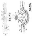
- FIG 9 shows a further embodiment in the invention in which a porous material 90 is used to disperse blast energies from an explosion.
- the porous material 90 comprises a plurality of layers 92, 94, and 96 of porous material fabricated from auxetic fibres in accordance with the principles described herein. It is also within the scope of the invention to utilise a single layer of porous material for this purpose, although it is believed that the use of a plurality of such porous materials enables blast energies to be dispersed more efficiently.
- Figure 9(a) shows the porous fabric 90 in a normal, relaxed configuration prior to a blast. This configuration can be considered to be one in which low tensile load is applied to the porous fabric 90.
- FIG. 9(b) shows the porous fabric 90 receiving blast energy from an explosion depicted schematically at 98.
- the blast front caused by the explosion is depicted schematically by the arrows 100 in Figure 9(b) .
- the blast front from the explosion 98 supplies a tensile load to, successively, the porous material layers 92, 94 and 96 which causes the pores 102 of the porous fabric layers 92, 94 and 96 to open.
- the provision of a plurality of porous fabric layers 92, 94 and 96 enables energy from the explosion 98 to be successively dispersed through the layers, and also through the voids 104 provided between the layers.
- the porous fabric layers employed in the porous fabric 90 are different, having different geometric parameters, such as fabric winding angle, pore size, fibre diameter, or different material characteristics, such as different fibre type.
- the invention is not limited to the embodiments and examples provided above. Rather, a wide range of applications can be envisaged in which the pore size of a porous material of the type provided by the invention is controlled for an advantageous purpose.
- breathable fabrics might be provided having a plurality of pores which open up when a wearer of the fabric undertakes an energetic activity, movement such as bending and stretching associated with the activity causing a tensile load to be applied to the fabric thereby causing the pores to open.
- the present invention can be used to control pore size by a way of reducing the size of the pores through application of compressive forces to the material.
- Porous materials for use in such applications might be provided by applying a tensile load to a porous material to strain the fibres and thus expand the pores, and then causing the material to set in order to retain the pores in the expanded configuration.
- Thermoset plastics materials might be used for this purpose.
- the application of a compressive force would reduce the pore size and cause the material to densify.
- Applications for such materials include shock dispersion applications, such as shock dispersion panels and body armour.
Landscapes
- Engineering & Computer Science (AREA)
- Textile Engineering (AREA)
- Mechanical Engineering (AREA)
- Chemical & Material Sciences (AREA)
- Chemical Kinetics & Catalysis (AREA)
- Filtering Materials (AREA)
- Nonwoven Fabrics (AREA)
Description
- This invention relates to uses of auxetic fibres, in particular to methods of using a porous material comprising a plurality of interconnected auxetic fibres.
- Auxetic materials are materials that have a negative or effectively negative Poisson's ratio. In contrast to most conventional materials, auxetic materials possess the property that under a tensile load the material expands perpendicularly to the axis along which the tensile load is applied. In other words, auxetic materials expand as they are stretched. Conversely, materials are also auxetic if a compressive load applied along an axis results in a reduction in the dimension of the material along an axis perpendicular to the axis along which the compressive load is applied. Most materials exhibit a positive Poisson's ratio, this ratio being defined by the ratio of the contractile transverse strain relative to the tensile longitudinal strain. Prior art auxetic materials can essentially be divided into two categories. One category comprises honeycomb like polymeric materials, and the other category comprises materials formed by particles linked by fibrils, such as materials described in the International Publication
WO 00/53830 - According to the invention there is provided a method dispersing high air pressures in accordance with the appended claims.
- Advantageously, the porous material comprises sheet material.
- It is preferred that the porous material comprises a fabric, which is typically, but not necessarily, a sheet material. It is advantageous that sheet material and fabrics can be readily produced using auxetic fibres of the type disclosed herein. Sheet materials and/or fabrics are useful in a range of application areas, such as textiles, which prior art auxetic materials of the type described above have little or no practical utility. Fabrics of the present may be woven, knitted, non-woven, felted, braided, netted or produced by any other suitable technique.
- The porous material may comprise three or more interconnected auxetic fibres. It is preferred that the auxetic fibres demonstrate auxetic properties over a substantial portion of the range of fibre lengths over which it is possible to stretch or compress the fibre without failure of the fibre.
- The auxetic fibres comprise a first component and a second component.
- The modulus of elasticity of the first component may be greater than the modulus of elasticity of the second component.
- Preferably, the first component and the second component extend generally longitudinally relative to an axis, and variation in a tensile or compressive load applied to the first component causes the radial position of the second component relative to the axis to vary.
- At least one of the first component and the second component is helically wrapped around the other component. It will become apparent to the skilled reader that, with a given auxetic fibre of this type, at some applied strains both the first and second components may be helically wrapped around the other component, but at other (higher) applied strains the first component may substantially straighten so as to no longer be helically wrapped around the second component. In principle, the second component might be substantially straight at low applied strain. The pores may be formed between adjacent auxetic fibres, wherein helices formed by the first components of the adjacent auxetic fibres are in-phase but of opposite handidness and helices formed by the second components of the adjacent auxetic fibres are in-phase but of opposite handidness. It will be appreciated by the skilled reader that, since it is possible that at some applied strains the first or second component might be substantially straight, it is not a necessary condition that helices are formed by both the first components, and the second components.
- The auxetic fibres may comprise a first component and a second component, the first component and the second component extending generally longitudinally relative to an axis, the first component being wrapped around the second component through one or more turns, the one or more turns being spaced longitudinally relative to the axis, variation in the tensile load on the first component causing the radial position of the second component relative to the axis to vary.
- The auxetic fibres may comprise a first component and a second component, the first component and second component extending generally longitudinally relative to an axis, the first component being wrapped around the second component through one or more turns, the first component having a higher modulus of elasticity than the second component, variation in the tensile or compressive load on the first component causing the radial position of the second component relative to the axis to vary.
- The auxetic fibres may comprise a first component and a second component, the first component and second component extending generally longitudinally relative to an axis, the first component being wrapped around the second component in a helical manner, variation in the tensile or compressive load on the first component causing variation in the diameter of the helix the first component follows, the variation in the diameter of the helix of the first component causing the second component to take on the form of a helix and/or causing the diameter of the helix of the second component to vary, the diameter of the second component helix increasing as the first component helix decreased in diameter, the diameter of the second component helix decreasing as the first component helix increases in diameter.
- The auxetic fibres and/or the porous material may have a negative Poisson's ratio. Fibres and/or materials having a Poisson's ratio of between 0 and -35 are preferred. The Poisson ratio of a fibre is in part dependent on the pitch of the first component. A steep pitch gives rise to a relatively low auxetic effect over a relatively large strain range whereas a shallow pitch gives rise to a relatively large auxetic effect over a relatively narrow strain range. In general, more negative Poisson's ratios are preferred.
- The first component may be a fibre, rod or hollow tube particularly of a relatively high modulus material. The first component may be formed of carbon fibre, glass fibre, polyaramids (e.g. Kevlar TM), polyamides (e.g. nylon), polyesters, polyalkalenes, polyethyleneterepthalate (PET), metal wire, cotton or other material. The materials from which the first component is formed may be natural or man made, inorganic or organic. The first component may be sealed with a cured film, for example a cured siloxane film. In the event that the first component is a hollow tube, the tube may contain additional materials.
- The second component may be a fibre, rod or hollow tube, particularly consisting of an intermediate or a low modulus material. The material is preferably capable of deformation without fracture. The second component may be formed of siloxane, liquid silicone rubber, natural rubber, nitrile rubber or other elastomeric material whether natural or man-made. However, the second component does not need to be elastomeric. For example, a polyamide such as nylon can be used advantageously, particularly in combination with a polyaramid as the first component.
- The first component may have a diameter that is between 0.01 and 1 times the diameter of the second component. The first component mayhave a cross-sectional area that is between 0.001 and 1 times the cross-sectional area of the second component.
- The first component and/or second component may be formed of a continuous material. Preferably the first component and/or second component are elongate. The first component and/or second component may be at least a hundred times as long as their maximum cross-sectional dimension or extent.
- The wrapping of the first component around the second component may be provided in the form of a covering or winding. The wrapping of the first component around the second component may be in the form of a spiral or helix. The spiral or helix may have a constant pitch along the second component. The pitch may be between zero degrees and ninety degrees relative to the axis.
- The second component may be linear with the first component wrapped around it. The second component may also be wrapped around the first component. The second component may be in the form of a spiral or helix. The pitch of the first component spiral or helix may be the same as the pitch of the second component spiral or helix.
- The porous material may comprise repeat units of two or more auxetic fibres. The auxetic fibres in the repeat units may be arranged around a core component. However, it is preferred that a core component is not employed.
- The pulse of air may be associated with blast energy from an explosion, or may be high pressure wind.
- The porous material may comprise a plurality of layers, each layer comprising a plurality of interconnected auxetic fibres. At least two layers may have different physical characteristics thereby improving the dispersion of the high air pressure. The physical characteristic may be pore size, fibre winding angle, fibre diameter or fibre type.
- Methods in accordance with the invention will now be described with reference to the accompanying drawings, in which:-
-
Figure 1 shows an auxetic fibre; -
Figure 2 shows a pair of adjacent auxetic fibres defining pores in a relaxed configuration; -
Figure 3 shows the pair of auxetic fibres depicted inFigure 2 under relatively high tensile load; -
Figure 4 shows an array of auxetic fibres with a relatively low strain applied thereto; -
Figure 5 shows an array of auxetic fibres with a relatively high strain applied thereto; -
Figure 6 shows a filter fabricated from auxetic fibres (a) at a relatively low applied strain and (b) a relatively high applied strain; -
Figure 7 shows (a) a plan view, (b) an exploded perspective view and (c) a crosssectional view of a fabric structure of the invention under relaxation conditions; -
Figure 8 shows (a) a plan view (b) an exploded perspective view and (c) a crosssectional view of a fabric structure of the invention when stretched; and -
Figure 9 shows a blast dispersing fabric of the invention (a) before use and (b) during use in dispersing a blast from an explosion. -
Figure 1 shows an auxetic fibre which may be utilised in the production of porous materials according to the invention. Theauxetic fibre 10 comprises afirst component 12 and asecond component 14. Thefirst component 12 is wrapped around the periphery of thesecond component 14 forming a helix. Typically, as shown inFigure 1 , the wrapping of thefirst component 12 around thesecond component 14 causes a deformation of thesecond component 14 from a generally linear configuration to a helical configuration. The first component is desirably formed from a material having a high modulus of elasticity, such as carbon fibre, Kevlar (RTM), glass fibre, wire, polyamides, polyesters, polyalkalenes, BET, or a natural fibre such as cotton. The second component is preferably formed from a material of lower modulus of elasticity than the first component. Examples of suitable materials include siloxane, silicone rubber, natural rubber, nitrile rubber or polyamides such as nylon. It should be noted that it is possible for the second component to be formed from a material of relatively high modulus of elasticity, such as nylon, provided it is used in combination with a first component formed from a material of higher modulus of elasticity. For example, nylon can be used in combination with a suitable first component such as a polyaramid. -
Figure 2 shows a pair ofauxetic fibres 10 of the type described above with reference toFigure 1 . It should be noted that the pair ofauxetic fibres pores 20. In particular, it should be noted that the helices formed by thefirst components auxetic fibres second components first components second components second components second components first components Figure 2 depicts the pair of adjacent auxetic fibres at relatively low applied tensile load.Figure 3 depicts the same pair ofauxetic fibres first components first components second components regions 22 in which thepores 20 are defined, onesecond component 14a is displaced to higher values of y whereas the othersecond component 14b is displaced to lower values of y. The effect of the displacements caused by the application of a tensile load is to increase the size of thepores 20. The present invention utilizes this phenomenon to advantageously control pore size in a variety of porous materials fabricated from auxetic fibres. Auxetic fibres of the type described give reference toFigure 1 are preferred. However, it is possible to utilise other auxetic fibres. For example, an auxetic fibre can be produced which consists of a plurality of auxetic fibres of the type shown inFigure 1 arranged around a core component. Thus, for example, an auxetic fibre might be produced utilising a pair auxetic fibres of the type shown inFigure 2 with a core component disposed between the auxetic fibres. The core component would extend generally longitudinally along the x axis. In this instance, the overall structure could be regarded as an auxetic fibre for use in producing a porous material. The present invention anticipates that further auxetic fibres will be developed, and that such auxetic fibres can be usefully incorporated into the present invention in a straightforward manner using the principles described herein. -
Figures 4 and5 depict aporous material 40. Theporous material 40 comprises an array of pairs of adjacent auxetic fibres of the type shown inFigures 2 and 3 . The array of pairs of auxetic yarns forms a flat sheet fabric. The fabric shown inFigures 4 and5 is a woven fabric, and for reasons of presentational simplicity, these Figures depict only the warp fibres. In other words, the weft threads are not shown inFigures 4 and5 , although the skilled reader will appreciate thatweft threads will be present in the woven fabric so as to interconnect warp fibres. Theweft fibres may be auxetic or non-auxetic in nature.Figure 4 depicts theporous material 40 with alow tensile load applied along the x axis. It can be seen that thepores 20 are essentially closed under such conditions.Figure 5 depicts theporous material 40 when a relatively large tensile load is applied along the x axis. It is seen that the application of the tensile load causes thepores 20 to open. By controlling the degree of strain in the material, it is possible to control the size of thepores 20. -
Figure 6a shows afilter material 60 made from auxetic fibres and defining a plurality ofpores 62.Figure 6a depicts thefilter 60 under conditions of low tensile load in the x direction. Under such conditions, thepores 62 are closed or at least of relatively small dimension.Figure 6b shows thefilter 60 under conditions of high tensile load applied along the x axis. Under such conditions of high tensile load, the dimensions thepores 62 increase, i.e. the pores open up. Thus, by stretching or relaxing a filter constructed from appropriately sized auxetic yarns, it is possible to maintain a close control over the pore size in the filter. For example, it is possible to maintain a desired pore size during the working lifetime of the filter, even if the filter becomes blocked by substrate particles during use. It is thus possible to leave a filter in situ for longer, saving on filter replacement and/or cleaning costs as well as reducing downtime. In a further advantageous embodiment, it is possible to clean the filter by applying a tensile load so as to stretch the filter to a configuration in which the pores are opened up sufficiently to allow trapped particles to be dislodged. It is possible to aid the cleaning process by use of a cleaning fluid, which may be a gas or a liquid. However, it is preferred that a cleaning fluid is not employed. In this way, energy consumption costs (which often exceed the cost of the filter) are reduced. Furthermore, it is possible to clean the filter without removing it or having to backflush. By varying the applied tensile load to the fiter, it is possible to utilize a single filter which is capable of providing a variety of pore sizes. Thus, a single filter can be used in a number of different applications. By using several layers of auxetic fabrics, it is possible to provide a filter having complex pore shapes. This may be achieved through the use of fabrics constructed from auxetic yarns made with different geometrical parameters, such as wind angle, relative diameters of auxetic yarn or material characteristics. The accurate control of pore size, possibly coupled with the provision of complex pore shapes, can permit higher process yields and allow the filtration of materials with specific structural shapes. It is believed that such methods will be particularly beneficial in the pharmaceutical industry. However, the invention is not limited to use in the pharmaceutical industry: rather, other industrial uses, such as other chemical applications, can be envisaged. Filters of the present invention can also be used in automotive applications. - In a further embodiment, the invention provides novel colour change fabrics.
Figure 7 shows acolour change fabric 70 which comprises abase fabric 72 overlaid by aporous material 74 made from auxetic fibres. Thebase fabric 72 is of a different colour compared to theporous fabric 74.Figure 7 shows thecolour change fabric 70 in a configuration in which low or no tensile load is applied to theporous fabric 74 along the x axis. In this instance, the pores (not shown) of theporous fabric 74 are substantially closed, and thus when thecolour change fabric 70 is viewed from above, the observer will see only theporous fabric 74. The observer will therefore associate the colour of theporous fabric 74 with thecolour changefabric 70.Figure 8 shows thecolour change fabric 70 in a configuration in which a relatively high tensile load is applied along the x axis. Under these conditions, pores 76 of theporous fabric 74 are caused to open up substantially (these pores being shown inFigure 8(a) ). Under these conditions, thebase fabric 72 becomes visible to an observer viewing thecolour change fabric 70 from above. Thus, to the observer, the appearance is given of a colour change. Depending on the dimensions of the auxetic fibres used in theporous fabric 74 and the precise structural details of theporous fabric 74, the observer may be able to discern theporous fabric 74 in the high tensile load configuration depicted inFigure 8 . In this instance, a complex geometrical pattern is seen by the observer. In other embodiments, theporous fabric 74 becomes essentially invisible to the observer, and thus the impression is given that the fabric has completely changed colour. Colour change fabrics of this type can be integrated into a range of garments for novelty and/or fashion purposes, in particular in conjunction with children's clothing. In such embodiments, the appearance of the garment can be changed through everyday use, e.g. through the wearer of the garment bending, stretching or otherwise moving. Garments of the invention include, but are not limited to, trousers, coats, hats, gloves, shirts, t-shirts, underwear, pullovers and other tops, socks and shoes. The invention is not limited to fabric. In particular, the base layer might comprise a non-fabric sheet such as a plastic sheet. The colour change fabric or other structures can be used to indicate the level of strain applied to the fabric or other structure. For example, .belts, ropes and webs might be produced for this purpose. The invention is not limited to embodiments in which a colour change is produced. For example, the base layer may have writing, images, logos or other signage located thereon which is revealed when a suitable tensile load is applied to the porous fabric layer. -
Figure 9 shows a further embodiment in the invention in which aporous material 90 is used to disperse blast energies from an explosion. Theporous material 90 comprises a plurality oflayers Figure 9(a) shows theporous fabric 90 in a normal, relaxed configuration prior to a blast. This configuration can be considered to be one in which low tensile load is applied to theporous fabric 90.Figure 9(b) shows theporous fabric 90 receiving blast energy from an explosion depicted schematically at 98. The blast front caused by the explosion is depicted schematically by thearrows 100 inFigure 9(b) . The blast front from the explosion 98 supplies a tensile load to, successively, the porous material layers 92, 94 and 96 which causes thepores 102 of the porous fabric layers 92, 94 and 96 to open. The provision of a plurality of porous fabric layers 92, 94 and 96 enables energy from the explosion 98 to be successively dispersed through the layers, and also through the voids 104 provided between the layers. It is preferred that the porous fabric layers employed in theporous fabric 90 are different, having different geometric parameters, such as fabric winding angle, pore size, fibre diameter, or different material characteristics, such as different fibre type. - The invention is not limited to the embodiments and examples provided above. Rather, a wide range of applications can be envisaged in which the pore size of a porous material of the type provided by the invention is controlled for an advantageous purpose. For example, breathable fabrics might be provided having a plurality of pores which open up when a wearer of the fabric undertakes an energetic activity, movement such as bending and stretching associated with the activity causing a tensile load to be applied to the fabric thereby causing the pores to open. Additionally, the present invention can be used to control pore size by a way of reducing the size of the pores through application of compressive forces to the material. Porous materials for use in such applications might be provided by applying a tensile load to a porous material to strain the fibres and thus expand the pores, and then causing the material to set in order to retain the pores in the expanded configuration. Thermoset plastics materials might be used for this purpose. The application of a compressive force would reduce the pore size and cause the material to densify. Applications for such materials include shock dispersion applications, such as shock dispersion panels and body armour.
Claims (10)
- A method of dispersing high air pressures comprising the steps of:providing a porous material comprising a plurality of interconnected auxetic fibres, In which the auxetic fibres comprise a first component and a second component, and at least one of the first component and the second component is helically wrapped around the other component; andexposing the porous material to a pulse of air of high pressure.
- A method according claim 1 in which the porous material comprises sheet material.
- A method according to claim 1 or claim 2 in which the porous material comprises a fabric.
- A method according to claim 3 in which the fabric is woven, knitted, nonwoven, felted, braided or netted.
- A method according to any previous claim in which the auxetic fibres comprise a first component and a second component, and the modulus of elasticity of the first component is greater than the modulus elasticity of the second component.
- A method according to any previous claim in which the auxetic fibres comprise a first component and a second component, the component, and the second component extending generally longitudinally relative to an axis, and variation in a tensile or compressive load applied to the first component causes the radial position of the second component relative to the axis to vary.
- A method according to any previous claim in which the porous material comprises a plurality of layers, each layer comprising a plurality of interconnected auxetic fibres.
- A method according to claim 7 in which at least two layers have different physical characteristics thereby improving the dispersion of the high pressure air.
- A method according to claim 8 in which the physical characteristic is pore size, fibre winding angle, fibre diameter or fibre type.
- A method according to any previous claim in which the pulse of air is associated with blast energy from an explosion.
Applications Claiming Priority (2)
| Application Number | Priority Date | Filing Date | Title |
|---|---|---|---|
| GB0418759A GB0418759D0 (en) | 2004-08-23 | 2004-08-23 | Uses of auxetic fibres |
| PCT/GB2005/003262 WO2006021763A1 (en) | 2004-08-23 | 2005-08-22 | Uses of auxetic fibres |
Publications (2)
| Publication Number | Publication Date |
|---|---|
| EP1786962A1 EP1786962A1 (en) | 2007-05-23 |
| EP1786962B1 true EP1786962B1 (en) | 2013-12-25 |
Family
ID=33042489
Family Applications (1)
| Application Number | Title | Priority Date | Filing Date |
|---|---|---|---|
| EP20050773180 Expired - Lifetime EP1786962B1 (en) | 2004-08-23 | 2005-08-22 | Uses of auxetic fibres |
Country Status (4)
| Country | Link |
|---|---|
| US (1) | US8002879B2 (en) |
| EP (1) | EP1786962B1 (en) |
| GB (1) | GB0418759D0 (en) |
| WO (1) | WO2006021763A1 (en) |
Families Citing this family (54)
| Publication number | Priority date | Publication date | Assignee | Title |
|---|---|---|---|---|
| US20080185115A1 (en) * | 2007-02-07 | 2008-08-07 | Antony Morton | Paper machine clothing with auxetic fibers and/or yarns |
| GB0818523D0 (en) * | 2008-10-09 | 2008-11-19 | Univ Exeter | Fibrous assembly |
| US8507746B2 (en) | 2008-12-16 | 2013-08-13 | Kimberly-Clark Worldwide, Inc. | Leakage-signaling absorbent article |
| US8225729B2 (en) | 2008-12-16 | 2012-07-24 | Kimberly-Clark Worldwide, Inc. | Three-dimensional wiping substrate and method therefor |
| US8882735B2 (en) | 2008-12-16 | 2014-11-11 | Kimberly-Clark Worldwide, Inc. | Article with fluid-activated barriers |
| US7858055B2 (en) * | 2008-12-18 | 2010-12-28 | Kimberly-Clark Worldwide, Inc. | Moisture sensitive auxetic material |
| US9693843B2 (en) * | 2009-05-22 | 2017-07-04 | Howard Cohen | Strainer/filter unit for an aspirating filtration system and method thereof |
| KR101779631B1 (en) | 2009-12-30 | 2017-09-18 | 쓰리엠 이노베이티브 프로퍼티즈 컴파니 | Method of making an auxetic mesh |
| PL2519327T3 (en) | 2009-12-30 | 2017-01-31 | 3M Innovative Properties Company | Molded auxetic mesh and manufacturing method |
| BR112012016094A2 (en) | 2009-12-30 | 2016-08-16 | 3M Innovative Properties Co | respirator with filtering facepiece having an auxetic mesh on the mask body |
| US8708988B2 (en) | 2010-12-03 | 2014-04-29 | Kimberly-Clark Worldwide, Inc. | Absorbent article configured for controlled deformation |
| US10206765B2 (en) | 2011-01-24 | 2019-02-19 | Leonard G. Lorch | Dental floss |
| US9277976B2 (en) | 2011-01-24 | 2016-03-08 | Leonard G. Lorch | Dental floss |
| US9277977B2 (en) | 2011-01-24 | 2016-03-08 | Leonard G. Lorch | Dental floss |
| FR2986013B1 (en) | 2012-01-24 | 2015-02-13 | Calyf | ELASTIC HYBRID CABLE AND METHOD FOR MANUFACTURING SUCH A CABLE |
| CN103287025B (en) * | 2012-02-28 | 2015-12-02 | 香港纺织及成衣研发中心有限公司 | Three-dimensional negative Poisson ratio interval knitted fabric and manufacturing method thereof |
| DE102012203784A1 (en) * | 2012-03-12 | 2013-09-12 | BSH Bosch und Siemens Hausgeräte GmbH | Water-conducting household appliance with an adjustable filter |
| CN103361811B (en) * | 2012-06-26 | 2016-03-30 | 香港理工大学 | Negative Poisson ratio yarn structure and manufacturing method thereof |
| US8573125B1 (en) * | 2012-07-13 | 2013-11-05 | Blast Control Systems, L.L.C. | Blast control blanket |
| US9241808B2 (en) | 2012-08-27 | 2016-01-26 | Anthony Sabatino | Auxetic prosthetic implant |
| US9554622B2 (en) | 2013-09-18 | 2017-01-31 | Nike, Inc. | Multi-component sole structure having an auxetic configuration |
| US9549590B2 (en) | 2013-09-18 | 2017-01-24 | Nike, Inc. | Auxetic structures and footwear with soles having auxetic structures |
| US9402439B2 (en) | 2013-09-18 | 2016-08-02 | Nike, Inc. | Auxetic structures and footwear with soles having auxetic structures |
| US9456656B2 (en) | 2013-09-18 | 2016-10-04 | Nike, Inc. | Midsole component and outer sole members with auxetic structure |
| US9554624B2 (en) * | 2013-09-18 | 2017-01-31 | Nike, Inc. | Footwear soles with auxetic material |
| US9554620B2 (en) | 2013-09-18 | 2017-01-31 | Nike, Inc. | Auxetic soles with corresponding inner or outer liners |
| US9538811B2 (en) | 2013-09-18 | 2017-01-10 | Nike, Inc. | Sole structure with holes arranged in auxetic configuration |
| US9962313B2 (en) * | 2014-02-11 | 2018-05-08 | Ronald G. Scott, Llc | Compression garment and method of forming the same |
| US9872537B2 (en) | 2014-04-08 | 2018-01-23 | Nike, Inc. | Components for articles of footwear including lightweight, selectively supported textile components |
| US9861162B2 (en) | 2014-04-08 | 2018-01-09 | Nike, Inc. | Components for articles of footwear including lightweight, selectively supported textile components |
| US9474326B2 (en) * | 2014-07-11 | 2016-10-25 | Nike, Inc. | Footwear having auxetic structures with controlled properties |
| US10064448B2 (en) | 2014-08-27 | 2018-09-04 | Nike, Inc. | Auxetic sole with upper cabling |
| US9854869B2 (en) | 2014-10-01 | 2018-01-02 | Nike, Inc. | Article of footwear with one or more auxetic bladders |
| US9901135B2 (en) | 2014-12-09 | 2018-02-27 | Nike, Inc. | Footwear with flexible auxetic ground engaging members |
| US9775408B2 (en) | 2014-12-09 | 2017-10-03 | Nike, Inc. | Footwear with auxetic ground engaging members |
| US9681703B2 (en) | 2014-12-09 | 2017-06-20 | Nike, Inc. | Footwear with flexible auxetic sole structure |
| US9668542B2 (en) | 2015-08-14 | 2017-06-06 | Nike, Inc. | Sole structure including sipes |
| US9635903B2 (en) | 2015-08-14 | 2017-05-02 | Nike, Inc. | Sole structure having auxetic structures and sipes |
| US10070688B2 (en) | 2015-08-14 | 2018-09-11 | Nike, Inc. | Sole structures with regionally applied auxetic openings and siping |
| DE102016225446B4 (en) | 2016-12-19 | 2018-12-20 | Bayerische Motoren Werke Aktiengesellschaft | Pressure tank with reinforcing fibers |
| CN108248018B (en) * | 2018-02-02 | 2021-06-04 | 东华大学 | A kind of 3D printing auxetic yarn, processing method and use |
| CN108166122A (en) * | 2018-02-08 | 2018-06-15 | 湖北枫树线业有限公司 | The bifilar sewing thread of single multifilament and its manufacturing method with drawn expanded performance |
| KR102288913B1 (en) * | 2018-08-16 | 2021-08-10 | 전남대학교산학협력단 | Synclatic curvature deformable sandwich panel and fabrication method thereof |
| FR3085130B1 (en) * | 2018-08-27 | 2020-10-02 | Safran Nacelles | MANUFACTURING PROCESS OF A PANEL FOR AN AIRCRAFT PROPULSIVE NACELLE |
| CN109289356B (en) * | 2018-10-30 | 2019-10-29 | 江苏氟美斯环保节能新材料有限公司 | A kind of smoke dust removing filtering bag |
| CN109289322B (en) * | 2018-10-30 | 2019-06-28 | 江苏臻中滤料科技有限公司 | A kind of easy-to-clean ash filter bag |
| CN111016334B (en) * | 2019-10-25 | 2021-01-01 | 青岛理工大学 | Knock-resistant and impact-resistant multi-level heterogeneous fiber preform composite material and preparation method thereof |
| CA3065707A1 (en) | 2019-12-20 | 2021-06-20 | Quanta Associates, L.P. | Implosion shield apparatus and method |
| CN113369476B (en) * | 2021-05-31 | 2022-08-02 | 西北有色金属研究院 | Preparation process of metal fiber porous material with three-dimensional positive and negative Poisson's ratio |
| US12137753B2 (en) | 2021-12-31 | 2024-11-12 | Under Armour, Inc. | Athletic bra |
| WO2024086387A2 (en) * | 2022-08-24 | 2024-04-25 | Massachusetts Institute Of Technology | High-performance mono-material hybrid yarns and textiles |
| CN116145300B (en) * | 2023-03-08 | 2024-04-30 | 苏州红旭新材料科技有限公司 | Electromagnetic shielding function elastic yarn with negative poisson ratio effect |
| CN117071141A (en) * | 2023-07-14 | 2023-11-17 | 东华大学 | A lead-free fabric that protects against X-rays |
| CN119121483B (en) * | 2024-09-14 | 2026-02-13 | 浙江理工大学 | A stretch-sensitive color-changing negative Poisson's ratio fabric, its preparation method and application |
Family Cites Families (8)
| Publication number | Priority date | Publication date | Assignee | Title |
|---|---|---|---|---|
| US3831369A (en) * | 1972-08-11 | 1974-08-27 | Spanco Yarns | Yarn structure and method of making same |
| NL182497C (en) * | 1976-11-26 | 1988-03-16 | Akzo Nv | METHOD FOR MANUFACTURING A FITTY STRAP, AND CABLES OR ROPES MADE THEREFROM |
| GB9723140D0 (en) * | 1997-11-04 | 1998-01-07 | British Nuclear Fuels Plc | Improvements in and relating to material separations |
| NZ333184A (en) * | 1998-12-03 | 2001-08-31 | Hanna Holdings Ltd | Yarn or rope made from short and springy fibres, with reinforcing thread(s), and yarn being twisted in alternate directions during travel |
| GB9905145D0 (en) * | 1999-03-06 | 1999-04-28 | Bolton Inst Higher Education | Auxetic materials |
| US7247265B2 (en) * | 2000-03-06 | 2007-07-24 | Auxetic Technologies Ltd. | Auxetic filamentary materials |
| US6743388B2 (en) | 2001-12-31 | 2004-06-01 | Advanced Cardiovascular Systems, Inc. | Process of making polymer articles |
| GB0307330D0 (en) | 2003-03-29 | 2003-05-07 | Dow Corning Ltd | Improvements in and relating to composite materials and structures |
-
2004
- 2004-08-23 GB GB0418759A patent/GB0418759D0/en not_active Ceased
-
2005
- 2005-08-22 US US11/574,178 patent/US8002879B2/en not_active Expired - Fee Related
- 2005-08-22 WO PCT/GB2005/003262 patent/WO2006021763A1/en not_active Ceased
- 2005-08-22 EP EP20050773180 patent/EP1786962B1/en not_active Expired - Lifetime
Also Published As
| Publication number | Publication date |
|---|---|
| EP1786962A1 (en) | 2007-05-23 |
| WO2006021763A1 (en) | 2006-03-02 |
| GB0418759D0 (en) | 2004-09-22 |
| US20070210011A1 (en) | 2007-09-13 |
| US8002879B2 (en) | 2011-08-23 |
Similar Documents
| Publication | Publication Date | Title |
|---|---|---|
| US8002879B2 (en) | Uses of auxetic fibres | |
| US9475257B2 (en) | Three dimensional negative poisson'S ratio spacer knitted fabric and method for making the same | |
| Hu et al. | Auxetic textile materials-a review | |
| CA2520687C (en) | Improvements in and relating to composite materials and structures | |
| CN106149150B (en) | Negative Poisson ratio woven fabric and manufacturing method thereof | |
| CN109154282B (en) | Actuating Textiles Containing Polymer Fiber Muscles | |
| US6834685B2 (en) | Bi-modulus reinforcement fabric | |
| Gao et al. | Manufacture and evaluation of auxetic yarns and woven fabrics | |
| CN104911804B (en) | A kind of two-dimentional knitted fabric of negative poisson's ratio and its method for weaving | |
| RU2698613C1 (en) | 3d woven blanks with channels | |
| JP5706924B2 (en) | Woven fabric with a pentagonal filament in cross section | |
| JP2019035160A (en) | Three-layer fabric | |
| CN107268185A (en) | A kind of method that blend spinning prepares the flexible auxetic materials of rock-steady structure | |
| CN105780244A (en) | Ribbon and sofa provided with ribbon | |
| CN107326499A (en) | A kind of foldable structure deforms the preparation method of auxetic yarn | |
| CN113897723A (en) | Forming method and application of negative Poisson ratio fabric with high shape memory and high elasticity | |
| IT8149169A1 (en) | Improvements in elastic bandages obtained by knitting | |
| EP4338633B1 (en) | Auxetic textile structures | |
| CN207091629U (en) | A kind of negative poisson's ratio woven fabric | |
| EP2470368A2 (en) | Multipurpose laminated stretch fabric | |
| Zulifqar | Study of auxetic woven fabrics | |
| CN224199575U (en) | Woven fabric with high strength and high air permeability and vamp with woven fabric | |
| WO1995013413A1 (en) | Textile fabric | |
| CN217021747U (en) | Crepe with high tearing strength | |
| CN104250873A (en) | Three-dimensional fabric |
Legal Events
| Date | Code | Title | Description |
|---|---|---|---|
| PUAI | Public reference made under article 153(3) epc to a published international application that has entered the european phase |
Free format text: ORIGINAL CODE: 0009012 |
|
| 17P | Request for examination filed |
Effective date: 20070321 |
|
| AK | Designated contracting states |
Kind code of ref document: A1 Designated state(s): AT BE BG CH CY CZ DE DK EE ES FI FR GB GR HU IE IS IT LI LT LU LV MC NL PL PT RO SE SI SK TR |
|
| DAX | Request for extension of the european patent (deleted) | ||
| 17Q | First examination report despatched |
Effective date: 20080708 |
|
| GRAP | Despatch of communication of intention to grant a patent |
Free format text: ORIGINAL CODE: EPIDOSNIGR1 |
|
| GRAS | Grant fee paid |
Free format text: ORIGINAL CODE: EPIDOSNIGR3 |
|
| GRAA | (expected) grant |
Free format text: ORIGINAL CODE: 0009210 |
|
| AK | Designated contracting states |
Kind code of ref document: B1 Designated state(s): AT BE BG CH CY CZ DE DK EE ES FI FR GB GR HU IE IS IT LI LT LU LV MC NL PL PT RO SE SI SK TR |
|
| REG | Reference to a national code |
Ref country code: GB Ref legal event code: FG4D |
|
| REG | Reference to a national code |
Ref country code: CH Ref legal event code: EP |
|
| RAP2 | Party data changed (patent owner data changed or rights of a patent transferred) |
Owner name: AUXETIX LIMITED |
|
| REG | Reference to a national code |
Ref country code: AT Ref legal event code: REF Ref document number: 646717 Country of ref document: AT Kind code of ref document: T Effective date: 20140115 |
|
| REG | Reference to a national code |
Ref country code: IE Ref legal event code: FG4D |
|
| REG | Reference to a national code |
Ref country code: DE Ref legal event code: R096 Ref document number: 602005042263 Country of ref document: DE Effective date: 20140220 |
|
| PG25 | Lapsed in a contracting state [announced via postgrant information from national office to epo] |
Ref country code: FI Free format text: LAPSE BECAUSE OF FAILURE TO SUBMIT A TRANSLATION OF THE DESCRIPTION OR TO PAY THE FEE WITHIN THE PRESCRIBED TIME-LIMIT Effective date: 20131225 Ref country code: LT Free format text: LAPSE BECAUSE OF FAILURE TO SUBMIT A TRANSLATION OF THE DESCRIPTION OR TO PAY THE FEE WITHIN THE PRESCRIBED TIME-LIMIT Effective date: 20131225 Ref country code: SE Free format text: LAPSE BECAUSE OF FAILURE TO SUBMIT A TRANSLATION OF THE DESCRIPTION OR TO PAY THE FEE WITHIN THE PRESCRIBED TIME-LIMIT Effective date: 20131225 |
|
| REG | Reference to a national code |
Ref country code: NL Ref legal event code: VDEP Effective date: 20131225 |
|
| REG | Reference to a national code |
Ref country code: AT Ref legal event code: MK05 Ref document number: 646717 Country of ref document: AT Kind code of ref document: T Effective date: 20131225 |
|
| REG | Reference to a national code |
Ref country code: LT Ref legal event code: MG4D |
|
| PG25 | Lapsed in a contracting state [announced via postgrant information from national office to epo] |
Ref country code: LV Free format text: LAPSE BECAUSE OF FAILURE TO SUBMIT A TRANSLATION OF THE DESCRIPTION OR TO PAY THE FEE WITHIN THE PRESCRIBED TIME-LIMIT Effective date: 20131225 |
|
| PG25 | Lapsed in a contracting state [announced via postgrant information from national office to epo] |
Ref country code: EE Free format text: LAPSE BECAUSE OF FAILURE TO SUBMIT A TRANSLATION OF THE DESCRIPTION OR TO PAY THE FEE WITHIN THE PRESCRIBED TIME-LIMIT Effective date: 20131225 Ref country code: IS Free format text: LAPSE BECAUSE OF FAILURE TO SUBMIT A TRANSLATION OF THE DESCRIPTION OR TO PAY THE FEE WITHIN THE PRESCRIBED TIME-LIMIT Effective date: 20140425 Ref country code: BE Free format text: LAPSE BECAUSE OF FAILURE TO SUBMIT A TRANSLATION OF THE DESCRIPTION OR TO PAY THE FEE WITHIN THE PRESCRIBED TIME-LIMIT Effective date: 20131225 |
|
| PG25 | Lapsed in a contracting state [announced via postgrant information from national office to epo] |
Ref country code: RO Free format text: LAPSE BECAUSE OF FAILURE TO SUBMIT A TRANSLATION OF THE DESCRIPTION OR TO PAY THE FEE WITHIN THE PRESCRIBED TIME-LIMIT Effective date: 20131225 Ref country code: ES Free format text: LAPSE BECAUSE OF FAILURE TO SUBMIT A TRANSLATION OF THE DESCRIPTION OR TO PAY THE FEE WITHIN THE PRESCRIBED TIME-LIMIT Effective date: 20131225 Ref country code: AT Free format text: LAPSE BECAUSE OF FAILURE TO SUBMIT A TRANSLATION OF THE DESCRIPTION OR TO PAY THE FEE WITHIN THE PRESCRIBED TIME-LIMIT Effective date: 20131225 Ref country code: CZ Free format text: LAPSE BECAUSE OF FAILURE TO SUBMIT A TRANSLATION OF THE DESCRIPTION OR TO PAY THE FEE WITHIN THE PRESCRIBED TIME-LIMIT Effective date: 20131225 Ref country code: CY Free format text: LAPSE BECAUSE OF FAILURE TO SUBMIT A TRANSLATION OF THE DESCRIPTION OR TO PAY THE FEE WITHIN THE PRESCRIBED TIME-LIMIT Effective date: 20131225 Ref country code: PL Free format text: LAPSE BECAUSE OF FAILURE TO SUBMIT A TRANSLATION OF THE DESCRIPTION OR TO PAY THE FEE WITHIN THE PRESCRIBED TIME-LIMIT Effective date: 20131225 Ref country code: PT Free format text: LAPSE BECAUSE OF FAILURE TO SUBMIT A TRANSLATION OF THE DESCRIPTION OR TO PAY THE FEE WITHIN THE PRESCRIBED TIME-LIMIT Effective date: 20140428 Ref country code: SK Free format text: LAPSE BECAUSE OF FAILURE TO SUBMIT A TRANSLATION OF THE DESCRIPTION OR TO PAY THE FEE WITHIN THE PRESCRIBED TIME-LIMIT Effective date: 20131225 Ref country code: NL Free format text: LAPSE BECAUSE OF FAILURE TO SUBMIT A TRANSLATION OF THE DESCRIPTION OR TO PAY THE FEE WITHIN THE PRESCRIBED TIME-LIMIT Effective date: 20131225 |
|
| REG | Reference to a national code |
Ref country code: DE Ref legal event code: R097 Ref document number: 602005042263 Country of ref document: DE |
|
| PG25 | Lapsed in a contracting state [announced via postgrant information from national office to epo] |
Ref country code: DK Free format text: LAPSE BECAUSE OF FAILURE TO SUBMIT A TRANSLATION OF THE DESCRIPTION OR TO PAY THE FEE WITHIN THE PRESCRIBED TIME-LIMIT Effective date: 20131225 |
|
| PLBE | No opposition filed within time limit |
Free format text: ORIGINAL CODE: 0009261 |
|
| STAA | Information on the status of an ep patent application or granted ep patent |
Free format text: STATUS: NO OPPOSITION FILED WITHIN TIME LIMIT |
|
| PGFP | Annual fee paid to national office [announced via postgrant information from national office to epo] |
Ref country code: FR Payment date: 20140829 Year of fee payment: 10 |
|
| 26N | No opposition filed |
Effective date: 20140926 |
|
| REG | Reference to a national code |
Ref country code: DE Ref legal event code: R097 Ref document number: 602005042263 Country of ref document: DE Effective date: 20140926 |
|
| PGFP | Annual fee paid to national office [announced via postgrant information from national office to epo] |
Ref country code: DE Payment date: 20140926 Year of fee payment: 10 |
|
| PG25 | Lapsed in a contracting state [announced via postgrant information from national office to epo] |
Ref country code: LU Free format text: LAPSE BECAUSE OF FAILURE TO SUBMIT A TRANSLATION OF THE DESCRIPTION OR TO PAY THE FEE WITHIN THE PRESCRIBED TIME-LIMIT Effective date: 20140822 Ref country code: MC Free format text: LAPSE BECAUSE OF FAILURE TO SUBMIT A TRANSLATION OF THE DESCRIPTION OR TO PAY THE FEE WITHIN THE PRESCRIBED TIME-LIMIT Effective date: 20131225 |
|
| REG | Reference to a national code |
Ref country code: CH Ref legal event code: PL |
|
| PG25 | Lapsed in a contracting state [announced via postgrant information from national office to epo] |
Ref country code: LI Free format text: LAPSE BECAUSE OF NON-PAYMENT OF DUE FEES Effective date: 20140831 Ref country code: CH Free format text: LAPSE BECAUSE OF NON-PAYMENT OF DUE FEES Effective date: 20140831 |
|
| REG | Reference to a national code |
Ref country code: IE Ref legal event code: MM4A |
|
| PG25 | Lapsed in a contracting state [announced via postgrant information from national office to epo] |
Ref country code: SI Free format text: LAPSE BECAUSE OF FAILURE TO SUBMIT A TRANSLATION OF THE DESCRIPTION OR TO PAY THE FEE WITHIN THE PRESCRIBED TIME-LIMIT Effective date: 20131225 |
|
| PG25 | Lapsed in a contracting state [announced via postgrant information from national office to epo] |
Ref country code: IE Free format text: LAPSE BECAUSE OF NON-PAYMENT OF DUE FEES Effective date: 20140822 |
|
| REG | Reference to a national code |
Ref country code: DE Ref legal event code: R119 Ref document number: 602005042263 Country of ref document: DE |
|
| PG25 | Lapsed in a contracting state [announced via postgrant information from national office to epo] |
Ref country code: BG Free format text: LAPSE BECAUSE OF FAILURE TO SUBMIT A TRANSLATION OF THE DESCRIPTION OR TO PAY THE FEE WITHIN THE PRESCRIBED TIME-LIMIT Effective date: 20131225 |
|
| REG | Reference to a national code |
Ref country code: FR Ref legal event code: ST Effective date: 20160429 |
|
| PG25 | Lapsed in a contracting state [announced via postgrant information from national office to epo] |
Ref country code: IT Free format text: LAPSE BECAUSE OF FAILURE TO SUBMIT A TRANSLATION OF THE DESCRIPTION OR TO PAY THE FEE WITHIN THE PRESCRIBED TIME-LIMIT Effective date: 20131225 Ref country code: GR Free format text: LAPSE BECAUSE OF FAILURE TO SUBMIT A TRANSLATION OF THE DESCRIPTION OR TO PAY THE FEE WITHIN THE PRESCRIBED TIME-LIMIT Effective date: 20140326 |
|
| PG25 | Lapsed in a contracting state [announced via postgrant information from national office to epo] |
Ref country code: DE Free format text: LAPSE BECAUSE OF NON-PAYMENT OF DUE FEES Effective date: 20160301 Ref country code: HU Free format text: LAPSE BECAUSE OF FAILURE TO SUBMIT A TRANSLATION OF THE DESCRIPTION OR TO PAY THE FEE WITHIN THE PRESCRIBED TIME-LIMIT; INVALID AB INITIO Effective date: 20050822 Ref country code: TR Free format text: LAPSE BECAUSE OF FAILURE TO SUBMIT A TRANSLATION OF THE DESCRIPTION OR TO PAY THE FEE WITHIN THE PRESCRIBED TIME-LIMIT Effective date: 20131225 |
|
| PG25 | Lapsed in a contracting state [announced via postgrant information from national office to epo] |
Ref country code: FR Free format text: LAPSE BECAUSE OF NON-PAYMENT OF DUE FEES Effective date: 20150831 |
|
| PGFP | Annual fee paid to national office [announced via postgrant information from national office to epo] |
Ref country code: GB Payment date: 20160822 Year of fee payment: 12 |
|
| GBPC | Gb: european patent ceased through non-payment of renewal fee |
Effective date: 20170822 |
|
| PG25 | Lapsed in a contracting state [announced via postgrant information from national office to epo] |
Ref country code: GB Free format text: LAPSE BECAUSE OF NON-PAYMENT OF DUE FEES Effective date: 20170822 |