EP1786490B1 - Method and system for providing an infusion device interface - Google Patents
Method and system for providing an infusion device interface Download PDFInfo
- Publication number
- EP1786490B1 EP1786490B1 EP05775721A EP05775721A EP1786490B1 EP 1786490 B1 EP1786490 B1 EP 1786490B1 EP 05775721 A EP05775721 A EP 05775721A EP 05775721 A EP05775721 A EP 05775721A EP 1786490 B1 EP1786490 B1 EP 1786490B1
- Authority
- EP
- European Patent Office
- Prior art keywords
- ferrule
- cannula
- bore
- infusion device
- proximal
- Prior art date
- Legal status (The legal status is an assumption and is not a legal conclusion. Google has not performed a legal analysis and makes no representation as to the accuracy of the status listed.)
- Expired - Lifetime
Links
Images




Classifications
-
- A—HUMAN NECESSITIES
- A61—MEDICAL OR VETERINARY SCIENCE; HYGIENE
- A61M—DEVICES FOR INTRODUCING MEDIA INTO, OR ONTO, THE BODY; DEVICES FOR TRANSDUCING BODY MEDIA OR FOR TAKING MEDIA FROM THE BODY; DEVICES FOR PRODUCING OR ENDING SLEEP OR STUPOR
- A61M5/00—Devices for bringing media into the body in a subcutaneous, intra-vascular or intramuscular way; Accessories therefor, e.g. filling or cleaning devices, arm-rests
- A61M5/14—Infusion devices, e.g. infusing by gravity; Blood infusion; Accessories therefor
-
- A—HUMAN NECESSITIES
- A61—MEDICAL OR VETERINARY SCIENCE; HYGIENE
- A61M—DEVICES FOR INTRODUCING MEDIA INTO, OR ONTO, THE BODY; DEVICES FOR TRANSDUCING BODY MEDIA OR FOR TAKING MEDIA FROM THE BODY; DEVICES FOR PRODUCING OR ENDING SLEEP OR STUPOR
- A61M25/00—Catheters; Hollow probes
- A61M25/0009—Making of catheters or other medical or surgical tubes
- A61M25/0014—Connecting a tube to a hub
-
- A—HUMAN NECESSITIES
- A61—MEDICAL OR VETERINARY SCIENCE; HYGIENE
- A61M—DEVICES FOR INTRODUCING MEDIA INTO, OR ONTO, THE BODY; DEVICES FOR TRANSDUCING BODY MEDIA OR FOR TAKING MEDIA FROM THE BODY; DEVICES FOR PRODUCING OR ENDING SLEEP OR STUPOR
- A61M5/00—Devices for bringing media into the body in a subcutaneous, intra-vascular or intramuscular way; Accessories therefor, e.g. filling or cleaning devices, arm-rests
-
- A—HUMAN NECESSITIES
- A61—MEDICAL OR VETERINARY SCIENCE; HYGIENE
- A61M—DEVICES FOR INTRODUCING MEDIA INTO, OR ONTO, THE BODY; DEVICES FOR TRANSDUCING BODY MEDIA OR FOR TAKING MEDIA FROM THE BODY; DEVICES FOR PRODUCING OR ENDING SLEEP OR STUPOR
- A61M5/00—Devices for bringing media into the body in a subcutaneous, intra-vascular or intramuscular way; Accessories therefor, e.g. filling or cleaning devices, arm-rests
- A61M5/14—Infusion devices, e.g. infusing by gravity; Blood infusion; Accessories therefor
- A61M5/158—Needles for infusions; Accessories therefor, e.g. for inserting infusion needles, or for holding them on the body
-
- A—HUMAN NECESSITIES
- A61—MEDICAL OR VETERINARY SCIENCE; HYGIENE
- A61M—DEVICES FOR INTRODUCING MEDIA INTO, OR ONTO, THE BODY; DEVICES FOR TRANSDUCING BODY MEDIA OR FOR TAKING MEDIA FROM THE BODY; DEVICES FOR PRODUCING OR ENDING SLEEP OR STUPOR
- A61M5/00—Devices for bringing media into the body in a subcutaneous, intra-vascular or intramuscular way; Accessories therefor, e.g. filling or cleaning devices, arm-rests
- A61M5/14—Infusion devices, e.g. infusing by gravity; Blood infusion; Accessories therefor
- A61M5/158—Needles for infusions; Accessories therefor, e.g. for inserting infusion needles, or for holding them on the body
- A61M2005/1587—Needles for infusions; Accessories therefor, e.g. for inserting infusion needles, or for holding them on the body suitable for being connected to an infusion line after insertion into a patient
-
- A—HUMAN NECESSITIES
- A61—MEDICAL OR VETERINARY SCIENCE; HYGIENE
- A61M—DEVICES FOR INTRODUCING MEDIA INTO, OR ONTO, THE BODY; DEVICES FOR TRANSDUCING BODY MEDIA OR FOR TAKING MEDIA FROM THE BODY; DEVICES FOR PRODUCING OR ENDING SLEEP OR STUPOR
- A61M39/00—Tubes, tube connectors, tube couplings, valves, access sites or the like, specially adapted for medical use
- A61M39/02—Access sites
- A61M39/04—Access sites having pierceable self-sealing members
Definitions
- the present invention generally relates to an infusion device. More particularly, the present invention relates to an infusion device, for example, a medical infusion set, that resists damage from a needle and that is better equipped to maintain hermeticity during use.
- an infusion device for example, a medical infusion set
- Devices such as ambulatory external medical devices, may deliver material, such as insulin or medication, into a patient's body through an infusion device that may include tubes, hollow needles, ferrules, or cannulas or combinations of components.
- infusion devices require interfaces, for example, between a ferrule and a cannula, that maintain hermeticity during use.
- the needle may pierce or score portions of the interface which may reduce hermeticity.
- conventional systems may not maintain sufficient sealing hermeticity during use.
- US 2002/0161332 discloses an infusion device.
- An infuser base has a bore extending through it.
- the bore has distal and proximal ends and includes a shoulder between those ends.
- a cannula is present, having distal and proximal ends, the cannula proximal end having an inside diameter.
- the cannula has a tubular section of increase outside diameter that therefore extends radially outward from the cannula proximal end.
- the cannula is positioned in the bore such that the tubular section is positioned adjacent the shoulder.
- a needle-guiding ferrule is provided that has a ferrule insertion portion and a ferrule tapered portion extending from the ferrule insertion portion with an increasing outside diameter and an increasing inside diameter.
- the ferrule is positioned in the bore such that the ferrule insertion portion, but no portion of the ferrule tapered portion, is received in the tubular section of the cannula.
- the purpose of the ferrule is to guide a needle as it is inserted and centre it within the cannula.
- the infusion device comprises an infuser base, a cannula and a ferrule.
- the infuser base has a bore extending therethrough.
- the bore has distal and proximal ends and includes a shoulder therebetween.
- the cannula has distal and proximal ends with the proximal end having an inside first diameter.
- a flange extends radially outward from the cannula proximal end and the cannula is positioned in the bore such that the flange is positioned adjacent the shoulder.
- the ferrule has an insertion portion, having an outside second diameter which is substantially equal to the first diameter, and a tapered portion extending from the insertion portion with an increasing diameter.
- the ferrule is positioned in the bore such that the insertion portion and a portion of the tapered portion are received in the cannula proximal end and the flange is compressed between the shoulder and the tapered portion to define a seal between the cannula and ferrule.
- the infusion device includes a robust Interface subassembly to maintain hermeticity during use. Moreover, the Interface subassembly may be tolerant of dose dimensional tolerances.
- the interface subassembly generally includes a ferrule and a cannula.
- the Interface subassembly is positionable in an Infuser base.
- the cannula may be configured to free float within the infuser base.
- the ferrule may comprise a stem, a tapered lead-in, and a cup.
- the ferrule may be configured to include a proximal seal.
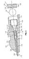
- FIG. 1 Illustrates infusion device 100 in which the features and principles of the present invention are Implemented.
- Infusion device 100 generally includes infuser base or housing 105 and interface subassembly 101.
- interface subassembly 101 generally comprises cannula 115 and ferrule 120.
- Infusion device 100 may further include septum 140 and retainer 136.
- Infuser base 105 includes body 102 having base surface 103 configured for position against or proximate an infusion site on a patient.
- the infuser base 105 may have an adhesive pad (not shown) or the like attached to base surface 103.
- Bore 104 extends through body 102 between distal end 106 and proximate end 107.
- Infuser base 105 may have various configurations.
- the present embodiment illustrates infuser base 105 configured for an angled insertion device with the central axis CA of bore 104 extending at an acute angle relative to base surface 103.
- infuser base 105 may have other configurations.
- infuser body 102' having bore 104' extending between proximal end 107' and distal end 106'.
- Bore 104' has a central axis CA that extends perpendicular to base surface 103' to provide a straight infusion device.
- Infusion device 100' otherwise generally operates In a manner similar to infusion device 100 as described herein.
- Bore 104 may include differing diameters between distal end 106 and proximal end 107.
- bore 104 of the present embodiments includes distal portion 108 having the smallest diameter b1 and proximal portion 114 having the largest diameter b4.
- a pair of intermediate portions 110 and 112 having intermediate diameters b2 and b3, respectively, are provided between distal and proximal portions 108 and 114.
- Shoulder 109 is defined between distal portion 108 and intermediate portion 110.
- Shoulder 111 is defined between intermediate portions 110 and 112.
- Shoulder 113 is defined between intermediate portion 112 and distal portion 114.
- Bore 104 may have other sizing arrangements.
- bore 104 of the present embodiment is cylindrical, it may have other geometric configurations.
- Cannula 115 is typically constructed of a medical-grade fluorocarbon-based polymer such as PTFE (PolyTetraFluoroEthylene) or other soft plastic material or non-plastic material.
- Cannula 115 of the present embodiment includes distal portion 116 having an outside diameter c1 and an inside diameter c3 and proximal portion 118 having an outside diameter c2 and an inside diameter c4.
- Cannula 115 is relatively thin material and therefore there is only a slight difference between the inside and outside diameters c1, c3 and c2, c4.
- the distal portion 116 diameters c1, c3 are smaller than the respective diameters c2, c4 of proximal portion 118.
- Tapered portion 117 extends between the distal and proximal portions 116 and 118 to account for the differences in diameter.
- the narrower distal portion 116 provides less pain and discomfort during insertion of cannula 115 into a patient while the wider proximal portion 118 allows for a wider receiving area for the insertion needle (not shown in the Fig.).
- Cannula 115 also includes flange 135 extending radially outwardly from proximal portion 118. Referring to Figs. 1 and 2 , cannula 115 is configured to be positioned in infuser base bore 104 with the cannula distal, tapered and proximal portions 116, 117, 118 generally positioned in distal bore portion 108 and flange 135 in contact with shoulder 109. Cannula distal portion 116 extends out of bore 104 beyond distal end 106 of base 105. The diameter b1 of bore distal portion 108 is larger than the outside diameters c1 and c2 of cannula portions 106 and 108, respectively, such that circumferential gap 150 (see Fig.
- gaps 150 and 151 are defined about cannula distal and tapered portions 116 and 117 and circumferential gap 151 (see Fig. 1 ) is defined about cannula proximal portion 118.
- gaps 150 and 151 will be described hereinafter.
- ferrule 120 has distal end 123 and proximal end 126 and generally includes narrow insertion portion 122 having an outside diameter f1, enlarged proximal portion 130 having an outside diameter f2 and tapered portion 125 therebetween.
- Ferrule 120 is desirably manufactured from stainless steel or a molded plastic or polymer, but is not limited to such and may be manufactured from various metals and non-metals.
- the outside diameter f1 of insertion portion 122 is substantially equal to the inside diameter c2 of cannula proximal end 118 such that insertion portion 122 may be received in cannula proximal end 118 with a press fit as shown in Fig. 3 .
- ferrule 120 is inserted into cannula 115 with a portion of ferrule tapered portion 125 entering cannula proximal end 118, as will be described in more detail hereinafter.
- the outside diameter f2 of enlarged proximal portion 130 is approximately equal to the inside diameter b3 of bore portion 112 such that enlarged proximal portion 130 is press fit into bore portion 112
- Ferrule enlarged proximal portion 130 has an inside diameter f3 and an inside axial length I1.
- Tapered portion 125 defines circumferential contact surface 127 at the junction with enlarged proximal portion 130.
- Contact surface 127 has a diameter f4 that is less than the diameter f3.
- Tapered portion 125 tapers to an inside diameter f5 proximate the insertion portion 122.
- Tapered portion 125 extends at an angle ⁇ between approximately 20 and 30 degrees, desirably 24 degrees. While tapered portion 125 is illustrated with linear sidewalls, tapered portion 125 is not limited to such.
- tapered portion 125 may have an axially arcuate configuration, such as a concave or convex arc, or a combination of axially arcuate and axially linear configurations.
- Soft elastomeric septum 140 is configured to be positioned in ferrule enlarged proximal portion 130 with an interference fit.
- Septum 140 desirably has a durometer of between approximately 30 shore A and 80 shore A, but is not limited to such.
- Septum 140 in the present embodiment is spherical and has a diameter s1 that is larger than the enlarged proximal portion inside diameter f3 and the enlarged proximal portion axial length I1.
- septum 140 compresses and forms primary circumferential seal 142 along an inside surface of enlarged proximal portion 130 and secondary circumferential seal 144 along circumferential contact surface 127.
- Both primary and secondary seals 142 and 144 desirably provide specific contact areas that span, for example, 360 degrees. Having dual seal locations desirably provides an advantage over conventional systems by adding double seal redundancy, however, the present invention is not limited to dual seals and may function with only one seal along either the inside surface of enlarged proximal portion 130 or the circumferential contact surface 127. While septum 140 of the present embodiment is spherical, it may have other configurations, for example, barrel or elliptical shapes, complementary to the configuration of ferrule 120 to provide compression contact seals along the inside surface of enlarged proximal portion 130 and/or circumferential contact surface 127.
- enlarged proximal portion 130 of the present embodiment has an axial length I1 smaller than septum diameter s1, such is not necessary.
- retainer 136 described hereinafter, may be configured with a distally extending portion configured to compress septum 140 toward circumferential contact surface 127.
- Retainer 136 of the present embodiment has body 137 with bore 138 therethrough.
- Body 137 has an outside diameter r1 that is equal to or slightly smaller than the inside diameter b4 of base bore portion 114 such that retainer 136 may be received within base bore 104.
- retainer 136 may be sonically welded or otherwise secured to infuser base 105.
- the diameter r1 may be slightly larger than the diameter b4 such that retainer 136 is press fit into base bore 104.
- retainer 136 contacts and compresses septum 140 in the distal direction.
- Retainer 136 may have tapered inlet 139 on at least one side thereof to assist in directing a needle or the like through bore 138.
- tapered inlet 139 is provided on both sides of retainer 136 such that retainer 136 is generally symmetrical, which may prevent it from being installed backwards during the manufacturing process.
- the invention is not so limited that tapered inlet 139 may be provided on only the inlet side of retainer 136.
- Ferrule insertion portion 122 is press fit into cannula proximal end 118 to an extent just before ferrule tapered portion 125 enters cannula 115.
- this integral interface subassembly 101 of cannula 115 and ferrule 120 is positioned into infuser base bore 104 with the cannula distal, tapered and proximal portions 116, 117, 118 generally positioned in distal bore portion 108 and flange 135 in contact with shoulder 109.
- Cannula distal portion 116 extends out of bore 104 beyond distal end 106 of base 105.
- cannula 115 may be positioned in base bore 104 and thereafter ferrule insertion portion 122 inserted into cannula proximal end 118.
- robust seal 160 is formed between cannula 115 and ferrule 120 upon fully seating subassembly 101 in infuser base 105.
- Subassembly 101 is pressed into infuser base bore 104 by forcing ferrule 120 in the distal direction.
- the distal force causes the under side of flange 135 to contact shoulder 109 in infuser base bore 104.
- Continued distal force causes ferrule tapered portion 125 to enter cannula proximal portion 118.
- the increasing diameter of ferrule tapered portion 125 causes flange 135 to expand radially. This expansion creates a tight taper seal 160 between the Internal surface of flange 135 and the external surface of flange tapered portion 125.
- Septum 140 and retainer 136 ara positioned as described above with retainer 136 maintaining ferrule 120 In the distally advanced position, thereby maintaining seal 160.
- the distal force upon ferrule 120 described above may be provided by insertion of retainer 136, or may be otherwise provided, for example, by a removable tool, and thereafter, retainer 136 positioned.
- this seal 160 over conventional systems is that It generally requires very little radial expansion of flange 135 to create a tight seal.
- the progressive taper of ferrule tapered portion 125 reduces the need for close tolerances on the axial movement of ferrule 120 relative to flange 135. Accordingly, mating components may be specified with generous tolerances, thus reducing the risk of manufacturing faulty product, for example.
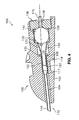
- ferrule tapered portion 125 will generally act to redirect the misaligned insertion needle 170 through distal end 123 of ferrule 120, such that it is again generally coaxial with cannula 115, without damaging or dulling the sharp tip of insertion needle 170.
- Selecting angle ⁇ as described above, to comprise a particular value or range of values between 20°-30° and desirably 24°, facilitates the aforementioned redirection of Insertion needle 170.
- ferrule tapered portion 125 also provides a free space area 180 for the distal end of infusion hub needle 175.
- Hub needle 175 is typically attached to an infusion tube or the like and is configured to be passed through septum 140 and retained attached to infusion device 100 to provide a communication path from the infusion tube to the flow path defined by ferrule 120 and cannula 115.
- Free space area 180 provides a generally open area for distal end 176 of hub needle 175. Free space area 180 generally prevents contact between hub needle distal end 176 and the inner surface of ferrule 120. No contact translates, for example, to minimal connect/disconnect forces of hub needle 175 to Infusion device 100.
- Free space area 180 is defined by circumferential shoulder 127 maintaining septum 140 in place and preventing It from being compressed substantially Into ferrule tapered portion 125, which may occur in a conventional assembly.
- cannula 115 and infuser base bore distal portion 108 are configured such that circumferential gap 150 Is defined about cannula distal and tapered portions 116 and 117 and circumferential gap 151 is defined about cannula proximal portion 118.
- Circumferential gaps 150 and 151 minimize the likellhood that cannula 115 will be damaged. For example, while it is unlikely cannula proximal portion 118 will be contacted by Insertion needle 170, circumferential gap 151 provides space for a slightly misaligned interface subassembly 101 from pinching cannula 115 against an Internal surface of infuser base 105 during assembly.
- Insertion needle 170 Is pushed through distal end 123 of ferrule 120, there may be misalignment of the components where the sharp tip or edges of insertion needle 170 may contact the Inner surface of cannula tapered portion 117. If there is no space for cannula 115 to deflect from the aforementioned misalignment, the sharp tip and/or edges of insertion needle 170 may cut through or significantly weaken the wall thickness at or distal the Inner surface of cannula tapered portion 117, which may Induce a leak. Consistent with embodiments of the invention, circumferential gaps 150 and 151 allow cannula 115 to flex about a center axis of infuser base bore 104, thus minimizing the risk of damage or leaks to cannula 115.
Landscapes
- Health & Medical Sciences (AREA)
- Life Sciences & Earth Sciences (AREA)
- Hematology (AREA)
- Animal Behavior & Ethology (AREA)
- Engineering & Computer Science (AREA)
- Anesthesiology (AREA)
- Biomedical Technology (AREA)
- Heart & Thoracic Surgery (AREA)
- Veterinary Medicine (AREA)
- Public Health (AREA)
- General Health & Medical Sciences (AREA)
- Vascular Medicine (AREA)
- Pulmonology (AREA)
- Biophysics (AREA)
- Infusion, Injection, And Reservoir Apparatuses (AREA)
- External Artificial Organs (AREA)
Abstract
Description
- The present invention generally relates to an infusion device. More particularly, the present invention relates to an infusion device, for example, a medical infusion set, that resists damage from a needle and that is better equipped to maintain hermeticity during use.
- Devices, such as ambulatory external medical devices, may deliver material, such as insulin or medication, into a patient's body through an infusion device that may include tubes, hollow needles, ferrules, or cannulas or combinations of components. Disposable infusion devices require interfaces, for example, between a ferrule and a cannula, that maintain hermeticity during use. In some situations, in conventional systems, the needle may pierce or score portions of the interface which may reduce hermeticity. Furthermore, conventional systems may not maintain sufficient sealing hermeticity during use.
-
US 2002/0161332 discloses an infusion device. An infuser base has a bore extending through it. The bore has distal and proximal ends and includes a shoulder between those ends. A cannula is present, having distal and proximal ends, the cannula proximal end having an inside diameter. The cannula has a tubular section of increase outside diameter that therefore extends radially outward from the cannula proximal end. The cannula is positioned in the bore such that the tubular section is positioned adjacent the shoulder. A needle-guiding ferrule is provided that has a ferrule insertion portion and a ferrule tapered portion extending from the ferrule insertion portion with an increasing outside diameter and an increasing inside diameter. The ferrule is positioned in the bore such that the ferrule insertion portion, but no portion of the ferrule tapered portion, is received in the tubular section of the cannula. The purpose of the ferrule is to guide a needle as it is inserted and centre it within the cannula. - In view of the foregoing, there is a need for an apparatus for providing an improved infusion device. Furthermore, there is a need for providing an infusion device that resists damage from a needle and is better equipped to maintain hermeticity during use.
- Consistent with embodiments of the present invention, systems and methods are disclosed for providing an infusion device.
- In one aspect of the present invention, the infusion device comprises an infuser base, a cannula and a ferrule. The infuser base has a bore extending therethrough. The bore has distal and proximal ends and includes a shoulder therebetween. The cannula has distal and proximal ends with the proximal end having an inside first diameter. A flange extends radially outward from the cannula proximal end and the cannula is positioned in the bore such that the flange is positioned adjacent the shoulder. The ferrule has an insertion portion, having an outside second diameter which is substantially equal to the first diameter, and a tapered portion extending from the insertion portion with an increasing diameter. The ferrule is positioned in the bore such that the insertion portion and a portion of the tapered portion are received in the cannula proximal end and the flange is compressed between the shoulder and the tapered portion to define a seal between the cannula and ferrule.
- It is to be understood that both the foregoing general description and the following detailed description are exemplary and explanatory only, and should not be considered restrictive of the scope of the invention, as described and claimed. Further, features and/or variations may be provided in addition to those set forth herein. For example, embodiments of the invention may be directed to various combinations and sub-combinations of the features described In the detailed description.
- Although the invention is illustrated and described herein with reference to specific embodiments, the invention is not intended to be limited to the details shown.
- It Is emphasized that, according to common practice, the various features of the drawings are not to scale. On the contrary, the dimensions of the various features are arbitrarily expanded or reduced for clarity. Included In the drawing are the following figures:
-
Fig. 1 is a cross-sectional view of an infusion device that is a first embodiment of the present invention; -
Fig. 2 Is an exploded view of the infusion device ofFig. 1 ; -
Fig. 3 Illustrates the infusion device ofFig. 2 partially assembled; -
Fig. 4 is a cross-sectional view similar toFig. 1 showing a misaligned Insertion needle partially inserted into the infusion device; -
Fig. 5 Is a cross-sectional view similar toFig. 1 showing a hub infusion needle Inserted Into the infusion device; and -
Fig. 6 Is a cross-sectional view of an infusion device that is an alternative embodiment of the prevent invention. - The following detailed description refers to the accompanying drawings. Wherever possible, the same reference numbers are used in the drawings and the following description to refer to the same or similar parts. While a presently desired embodiment and features of the invention are described herein, modifications, adaptations and other implementations of the claimed invention are possible. For example, substitutions, additions or modifications may be made to the components illustrated In the drawings, and the exemplary methods described herein may be modified by substituting, reordering, or adding steps to the disclosed methods. Accordingly, the following detailed description does not limit the invention. Instead, the proper scope of the invention is defined by the appended claims.
- Systems and methods consistent with the invention provide an infusion device which can be attached to the skin of a patient, and to which a supply of liquid medicine, e.g., an insulin pump, may be attached via a hub infusion needle or the like. The infusion device includes a robust Interface subassembly to maintain hermeticity during use. Moreover, the Interface subassembly may be tolerant of dose dimensional tolerances. The interface subassembly generally includes a ferrule and a cannula. The Interface subassembly is positionable in an Infuser base. The cannula may be configured to free float within the infuser base. The ferrule may comprise a stem, a tapered lead-in, and a cup. The ferrule may be configured to include a proximal seal.
- By way of a non-limiting example,
Fig. 1 Illustratesinfusion device 100 in which the features and principles of the present invention are Implemented. As shown InFig. 1 ,Infusion device 100 generally includes infuser base orhousing 105 andinterface subassembly 101.interface subassembly 101 generally comprisescannula 115 andferrule 120.Infusion device 100 may further includeseptum 140 andretainer 136. - Referring to
Fig. 2 , the components of the Infusion device will be described, Infuserbase 105 includesbody 102 havingbase surface 103 configured for position against or proximate an infusion site on a patient. Theinfuser base 105 may have an adhesive pad (not shown) or the like attached tobase surface 103. Bore 104 extends throughbody 102 betweendistal end 106 andproximate end 107. Infuserbase 105 may have various configurations. For example, the present embodiment illustratesinfuser base 105 configured for an angled insertion device with the central axis CA ofbore 104 extending at an acute angle relative tobase surface 103.infuser base 105 may have other configurations. For example, Infusion device 100' illustrated InFig. 6 includes infuser body 102' having bore 104' extending between proximal end 107' and distal end 106'. Bore 104' has a central axis CA that extends perpendicular to base surface 103' to provide a straight infusion device. Infusion device 100' otherwise generally operates In a manner similar toinfusion device 100 as described herein. -
Bore 104 may include differing diameters betweendistal end 106 andproximal end 107. For example, bore 104 of the present embodiments includesdistal portion 108 having the smallest diameter b1 andproximal portion 114 having the largest diameter b4. A pair ofintermediate portions proximal portions Shoulder 109 is defined betweendistal portion 108 andintermediate portion 110.Shoulder 111 is defined betweenintermediate portions Shoulder 113 is defined betweenintermediate portion 112 anddistal portion 114.Bore 104 may have other sizing arrangements. Furthermore, whilebore 104 of the present embodiment is cylindrical, it may have other geometric configurations. -
Cannula 115 is typically constructed of a medical-grade fluorocarbon-based polymer such as PTFE (PolyTetraFluoroEthylene) or other soft plastic material or non-plastic material.Cannula 115 of the present embodiment includesdistal portion 116 having an outside diameter c1 and an inside diameter c3 andproximal portion 118 having an outside diameter c2 and an inside diameter c4.Cannula 115 is relatively thin material and therefore there is only a slight difference between the inside and outside diameters c1, c3 and c2, c4. Thedistal portion 116 diameters c1, c3 are smaller than the respective diameters c2, c4 ofproximal portion 118.Tapered portion 117 extends between the distal andproximal portions distal portion 116 provides less pain and discomfort during insertion ofcannula 115 into a patient while the widerproximal portion 118 allows for a wider receiving area for the insertion needle (not shown in the Fig.). -
Cannula 115 also includesflange 135 extending radially outwardly fromproximal portion 118. Referring toFigs. 1 and2 ,cannula 115 is configured to be positioned in infuser base bore 104 with the cannula distal, tapered andproximal portions distal bore portion 108 andflange 135 in contact withshoulder 109. Cannuladistal portion 116 extends out ofbore 104 beyonddistal end 106 ofbase 105. The diameter b1 of boredistal portion 108 is larger than the outside diameters c1 and c2 ofcannula portions Fig. 1 ) is defined about cannula distal andtapered portions Fig. 1 ) is defined about cannulaproximal portion 118. The functions ofgaps - Referring again to
Fig. 2 ,ferrule 120 hasdistal end 123 andproximal end 126 and generally includesnarrow insertion portion 122 having an outside diameter f1, enlargedproximal portion 130 having an outside diameter f2 and taperedportion 125 therebetween.Ferrule 120 is desirably manufactured from stainless steel or a molded plastic or polymer, but is not limited to such and may be manufactured from various metals and non-metals. The outside diameter f1 ofinsertion portion 122 is substantially equal to the inside diameter c2 of cannulaproximal end 118 such thatinsertion portion 122 may be received in cannulaproximal end 118 with a press fit as shown inFig. 3 . Upon final assembly, seeFig. 1 ,ferrule 120 is inserted intocannula 115 with a portion of ferrule taperedportion 125 entering cannulaproximal end 118, as will be described in more detail hereinafter. The outside diameter f2 of enlargedproximal portion 130 is approximately equal to the inside diameter b3 ofbore portion 112 such that enlargedproximal portion 130 is press fit intobore portion 112 - Ferrule enlarged
proximal portion 130 has an inside diameter f3 and an inside axial length I1.Tapered portion 125 definescircumferential contact surface 127 at the junction with enlargedproximal portion 130.Contact surface 127 has a diameter f4 that is less than the diameter f3.Tapered portion 125 tapers to an inside diameter f5 proximate theinsertion portion 122.Tapered portion 125 extends at an angle θ between approximately 20 and 30 degrees, desirably 24 degrees. Whiletapered portion 125 is illustrated with linear sidewalls, taperedportion 125 is not limited to such. For example, taperedportion 125 may have an axially arcuate configuration, such as a concave or convex arc, or a combination of axially arcuate and axially linear configurations. - Soft
elastomeric septum 140 is configured to be positioned in ferrule enlargedproximal portion 130 with an interference fit.Septum 140 desirably has a durometer of between approximately 30 shore A and 80 shore A, but is not limited to such.Septum 140 in the present embodiment is spherical and has a diameter s1 that is larger than the enlarged proximal portion inside diameter f3 and the enlarged proximal portion axial length I1. As such, whenseptum 140 is positioned in ferrule enlargedproximal portion 130, as shown inFig. 1 ,septum 140 compresses and forms primarycircumferential seal 142 along an inside surface of enlargedproximal portion 130 and secondarycircumferential seal 144 alongcircumferential contact surface 127. Both primary andsecondary seals proximal portion 130 or thecircumferential contact surface 127. Whileseptum 140 of the present embodiment is spherical, it may have other configurations, for example, barrel or elliptical shapes, complementary to the configuration offerrule 120 to provide compression contact seals along the inside surface of enlargedproximal portion 130 and/orcircumferential contact surface 127. Furthermore, while enlargedproximal portion 130 of the present embodiment has an axial length I1 smaller than septum diameter s1, such is not necessary. Instead, for example,retainer 136, described hereinafter, may be configured with a distally extending portion configured to compressseptum 140 towardcircumferential contact surface 127. -
Retainer 136 of the present embodiment hasbody 137 withbore 138 therethrough.Body 137 has an outside diameter r1 that is equal to or slightly smaller than the inside diameter b4 of base boreportion 114 such thatretainer 136 may be received withinbase bore 104. In such a configuration,retainer 136 may be sonically welded or otherwise secured toinfuser base 105. Alternatively, the diameter r1 may be slightly larger than the diameter b4 such thatretainer 136 is press fit intobase bore 104. As best shown inFig. 1 , in the installed position,retainer 136 contacts and compressesseptum 140 in the distal direction.Retainer 136 may have taperedinlet 139 on at least one side thereof to assist in directing a needle or the like throughbore 138. In the present embodiment, taperedinlet 139 is provided on both sides ofretainer 136 such thatretainer 136 is generally symmetrical, which may prevent it from being installed backwards during the manufacturing process. The invention is not so limited thattapered inlet 139 may be provided on only the inlet side ofretainer 136. - Assembly of
infusion device 100 of the present invention will be described with reference toFigs. 1 and3 .Ferrule insertion portion 122 is press fit into cannulaproximal end 118 to an extent just before ferrule taperedportion 125 enterscannula 115. Referring toFig. 3 , thisintegral interface subassembly 101 ofcannula 115 andferrule 120 is positioned into infuser base bore 104 with the cannula distal, tapered andproximal portions distal bore portion 108 andflange 135 in contact withshoulder 109. Cannuladistal portion 116 extends out ofbore 104 beyonddistal end 106 ofbase 105. While the present embodiment includes interconnection ofcannula 115 andferrule 120 prior to positioning in infuser base bore 104, such is not required. For example,cannula 115 may be positioned in base bore 104 and thereafter ferruleinsertion portion 122 inserted into cannulaproximal end 118. - Referring again to
Fig. 1 ,robust seal 160 is formed betweencannula 115 andferrule 120 upon fully seatingsubassembly 101 ininfuser base 105.Subassembly 101 is pressed into infuser base bore 104 by forcingferrule 120 in the distal direction. The distal force causes the under side offlange 135 to contactshoulder 109 in infuser base bore 104. Continued distal force causes ferrule taperedportion 125 to enter cannulaproximal portion 118. The increasing diameter of ferrule taperedportion 125 causes flange 135 to expand radially. This expansion creates atight taper seal 160 between the Internal surface offlange 135 and the external surface of flange taperedportion 125.Septum 140 andretainer 136 ara positioned as described above withretainer 136 maintainingferrule 120 In the distally advanced position, thereby maintainingseal 160. The distal force uponferrule 120 described above may be provided by insertion ofretainer 136, or may be otherwise provided, for example, by a removable tool, and thereafter,retainer 136 positioned. - One advantage of this
seal 160 over conventional systems is that It generally requires very little radial expansion offlange 135 to create a tight seal. For example, the progressive taper of ferrule taperedportion 125 reduces the need for close tolerances on the axial movement offerrule 120 relative toflange 135. Accordingly, mating components may be specified with generous tolerances, thus reducing the risk of manufacturing faulty product, for example. - Additional advantages of ferrule tapered
portion 125 will be explained with reference toFigs. 4 and5 . As shown inFig. 4 , ifinsertion needle 170, configured to be passed completely throughcannula 115 and into a patient, Is inserted throughretainer 136 andseptum 140 in a misaligned orientation, i.e., angled relative to cannula 115 centerline,needle 170 will contact taperedportion 125 offerrule 120. Ferruletapered portion 125 will generally act to redirect themisaligned insertion needle 170 throughdistal end 123 offerrule 120, such that it is again generally coaxial withcannula 115, without damaging or dulling the sharp tip ofinsertion needle 170. Selecting angle θ, as described above, to comprise a particular value or range of values between 20°-30° and desirably 24°, facilitates the aforementioned redirection ofInsertion needle 170. - Referring to
Fig. 5 , ferrule taperedportion 125 also provides afree space area 180 for the distal end ofinfusion hub needle 175.Hub needle 175 is typically attached to an infusion tube or the like and is configured to be passed throughseptum 140 and retained attached toinfusion device 100 to provide a communication path from the infusion tube to the flow path defined byferrule 120 andcannula 115.Free space area 180 provides a generally open area fordistal end 176 ofhub needle 175.Free space area 180 generally prevents contact between hub needledistal end 176 and the inner surface offerrule 120. No contact translates, for example, to minimal connect/disconnect forces ofhub needle 175 toInfusion device 100.Free space area 180 is defined bycircumferential shoulder 127 maintainingseptum 140 in place and preventing It from being compressed substantially Into ferrule taperedportion 125, which may occur in a conventional assembly. - As explained above with reference to
Figs. 1 and2 ,cannula 115 and infuser base boredistal portion 108 are configured such thatcircumferential gap 150 Is defined about cannula distal andtapered portions circumferential gap 151 is defined about cannulaproximal portion 118.Circumferential gaps proximal portion 118 will be contacted byInsertion needle 170,circumferential gap 151 provides space for a slightlymisaligned interface subassembly 101 from pinchingcannula 115 against an Internal surface ofinfuser base 105 during assembly. - Furthermore, as
Insertion needle 170 Is pushed throughdistal end 123 offerrule 120, there may be misalignment of the components where the sharp tip or edges ofinsertion needle 170 may contact the Inner surface of cannula taperedportion 117. If there is no space forcannula 115 to deflect from the aforementioned misalignment, the sharp tip and/or edges ofinsertion needle 170 may cut through or significantly weaken the wall thickness at or distal the Inner surface of cannula taperedportion 117, which may Induce a leak. Consistent with embodiments of the invention,circumferential gaps cannula 115 to flex about a center axis of infuser base bore 104, thus minimizing the risk of damage or leaks tocannula 115. - While certain features and embodiments of the claimed invention have been described, other embodiments of the invention will be apparent to those skilled In the art from consideration of the specification and practice of the embodiments of the invention disclosed herein. It is Intended, therefore, that the specification be considered as exemplary only, with the true scope of the invention being indicated by the following claims. Although the invention is illustrated and described herein with reference to specific embodiments, the invention is not intended to be limited to the details shown. Rather, various modifications may be made in the details within the scope of the claims and without departing from the Invention.
Claims (24)
- An infusion device (100) comprising:an infuser base (105) having a bore (104) extending therethough, the bore (104) having distal and proximal ends and including a shoulder (109) therebetween;a cannula (115) having distal and proximal ends, the cannula proximal end (118) having an inside diameter, with a flange (135) extending radially outward from the cannula proximal end (118), the cannula (115) being positioned in the bore (104) such that the flange (135) is positioned adjacent the shoulder (109); anda ferrule (120) having a ferrule insertion portion (122), having an outside diameter which is substantially equal to the cannula proximal end inside diameter, and a ferrule tapered portion (125) extending from the ferrule insertion portion (122) with an increasing outside diameter, the ferrule (120) being positioned in the bore (104) such that the ferrule insertion portion (122) and a portion of the ferrule tapered portion (125) are received in the cannula proximal end (118) and the flange (135) is compressed between the shoulder (109) and the ferrule tapered portion (125) to define a seal between the cannula (115) and ferrule (120).
- An infusion device (100) according to claim 1 wherein the infuser base (105) has a base surface (103) and the bore (104) has a central axis (CA) that is at an acute angle relative to the base surface (103).
- An infusion device (100) according to claim 1 wherein the infuser base (105) has a base surface (103) and the bore (104) has a central axis (CA) that is at a right angle relative to the base surface (103).
- An infusion device (100) according to claim 1 wherein the bore (104) includes a bore distal portion (108) having an inside diameter and wherein the cannula (115) includes a cannula distal portion (116) extending in the bore distal portion (108) and having an outside diameter, the cannula distal portion (116) outside diameter being less than the bore distal portion (108) inside diameter such that a first circumferential gap (150) is formed about the cannula distal portion (116).
- An infusion device (100) according to claim 1 wherein the bore (104) includes a bore distal portion (108) having an inside diameter and wherein the cannula (115) includes:a cannula distal portion (116) extending in the bore distal portion (108) and having an outside diameter;a cannula proximal portion (118) extending in the bore distal portion (108) and having an outside diameter, the cannula proximal portion (118) outside diameter being greater than the cannula distal portion (116) outside diameter; anda cannula tapered portion (117) extending between the cannula distal portion (116) and the cannula proximal portion (118);wherein the cannula distal portion (116) outside diameter and the cannula proximal portion (118) outside diameter are less than the bore distal portion (108) inside diameter such that at least a first circumferential gap (150) is formed about the cannula distal portion (116), the cannula tapered portion (117) and the cannula proximal portion (118).
- An infusion device (100) according to claim 1 wherein the cannula (115) is spaced from an inside surface of the bore (104) except for at the cannula flange (135).
- An infusion device (100) according to claim 1 wherein the ferrule (120) includes a ferrule proximal portion (130) extending from the ferrule tapered portion (125) and having an inside surface having a inside diameter.
- An infusion device (100) according to claim 7 wherein a circumferential contact surface (127) is defined at a junction between the ferrule tapered portion (125) and the ferrule proximal portion (130), the circumferential contact surface (127) having an inside diameter that is less than the ferrule proximal portion inside surface diameter.
- An infusion device (100) according to claim 8 further comprising an elastomeric septum (140) having an outside radial dimension larger than the ferrule proximal portion inside surface diameter, wherein the elastomeric septum (140) is compressed in the ferrule proximal portion (130) and defines at least a first circumferential seal (142) between the septum (140) and the ferrule proximal portion inside surface or between the septum (140) and the cimumferential contact surface (127).
- An infusion device (100) according to claim 9 wherein the elastomeric septum (140) further defines a second seal between the other of the ferrule proximal portion inside surface and the circumferential contact surface (127).
- An infusion device (100) according to claim 9 wherein the ferrule proximal portion (130) has an axial length that is less than an axial length of the elastomeric septum (140).
- An infusion device (100) according to claim 9 wherein the septum (140) is substantially spherical.
- An infusion device (100) according to claim 9 further comprising a retainer (136) positioned in the bore (104) in contact with the septum (140) to retain the septum (140) in sealing engagement with the circumferential contact surface (127).
- An infusion device (100) according to claim 9 wherein the circumferential contact surface (127) is configured to prevent the septum (140) from extending significantly into the ferrule tapered portion (125) such that a free space area is defined within the ferrule tapered portion (125) between an inside surface thereof and the septum (140).
- An infusion device (100) according to claim 1 wherein the ferrule tapered portion (125) has a conical taper of between approximately 20 and 30 degrees.
- An infusion device (100) according to claim 15 wherein the conical taper is approximately 24 degrees.
- An infusion device (100) according to claim 1 wherein the tapered portion has an axially linear configuration.
- An infusion device (100) according to claim 1 wherein the tapered portion has an axially arcuate configuration.
- A method of assembling an infusion device (100) comprising:providing an infuser base (105) having a bore (104) extending therethrough, the bore (104) having distal and proximal ends and including a shoulder (109) therebetween; positioning a cannula (115), having distal and proximal ends and a flange (135) extending radially outward from the cannula proximal end (118), in the bore (104) such that the flange (135) is positioned adjacent the shoulder (109);positioning a ferrule (120), having a ferrule insertion portion (122) with an outside diameter which is substantially equal to an inside diameter of the cannula proximal end (118) and a ferrule tapered portion (125) extending from the ferrule insertion portion (122) with an increasing outside diameter, in the bore (104) such that the ferrule insertion portion (122) is received in the cannula proximal end (118); andadvancing the ferrule (120) distally such that a portion of the ferrule tapered portion (125) is received in the cannula proximale end (118) and the flange (135) is compressed between the shoulder (109) and the ferrule tapered portion (125) to define a seal between the cannula (115) and ferrule (120).
- The method according to claim 19 wherein the ferrule insertion portion (122) is positioned in the cannula proximal end (118) before the cannula (115) and ferrule (120) are positioned in the bore (104).
- The method according to claim 19 wherein advancing the ferrule (120) distally includes positioning a retainer (136) in the bore (104) such that the retainer (136) contacts and advances the ferrule (120).
- The method according to claim 19 wherein the ferrule (120) distally includes advancing the ferrule (120) with a removable tool and thereafter positioning a retainer (136) in the bore (104) to retain the ferrule (120) in an advanced position.
- The method according to claim 19 further comprising:compressing an elastomeric septum (140) in a ferrule proximal portion (130) extending from the ferrule tapered portion (125) and defining an inner surface and a circumferential contact surface (127) at a junction with the tapered surface such that the elastomeric septum (140) defines at least a first circumferential seal (142) between the septum (140) and the inside surface of the ferrule proximal portion (130) or between the septum (140) and the circumferential contact surface (127).
- The method according to claim 23 wherein the elastomeric septum (140) further defines a second seal (144) between the other of the ferrule proximal portion inside surface and the circumferential contact surface (127).
Priority Applications (2)
| Application Number | Priority Date | Filing Date | Title |
|---|---|---|---|
| PL05775721T PL1786490T3 (en) | 2004-07-21 | 2005-07-21 | Method and system for providing an infusion device interface |
| EP12153789.8A EP2450071B1 (en) | 2004-07-21 | 2005-07-21 | Infusion device |
Applications Claiming Priority (2)
| Application Number | Priority Date | Filing Date | Title |
|---|---|---|---|
| US58962304P | 2004-07-21 | 2004-07-21 | |
| PCT/US2005/025931 WO2006012446A2 (en) | 2004-07-21 | 2005-07-21 | Method and systems for providing an infusion device interface |
Publications (3)
| Publication Number | Publication Date |
|---|---|
| EP1786490A2 EP1786490A2 (en) | 2007-05-23 |
| EP1786490A4 EP1786490A4 (en) | 2010-04-21 |
| EP1786490B1 true EP1786490B1 (en) | 2012-02-08 |
Family
ID=35786709
Family Applications (2)
| Application Number | Title | Priority Date | Filing Date |
|---|---|---|---|
| EP05775721A Expired - Lifetime EP1786490B1 (en) | 2004-07-21 | 2005-07-21 | Method and system for providing an infusion device interface |
| EP12153789.8A Expired - Lifetime EP2450071B1 (en) | 2004-07-21 | 2005-07-21 | Infusion device |
Family Applications After (1)
| Application Number | Title | Priority Date | Filing Date |
|---|---|---|---|
| EP12153789.8A Expired - Lifetime EP2450071B1 (en) | 2004-07-21 | 2005-07-21 | Infusion device |
Country Status (13)
| Country | Link |
|---|---|
| US (1) | US8157773B2 (en) |
| EP (2) | EP1786490B1 (en) |
| JP (1) | JP2008507357A (en) |
| KR (1) | KR101233128B1 (en) |
| CN (1) | CN100536945C (en) |
| AT (1) | ATE544482T1 (en) |
| AU (1) | AU2005267057C1 (en) |
| CA (2) | CA2806525C (en) |
| ES (2) | ES2378771T3 (en) |
| IL (1) | IL180473A (en) |
| MX (1) | MX2007000768A (en) |
| PL (1) | PL1786490T3 (en) |
| WO (1) | WO2006012446A2 (en) |
Families Citing this family (21)
| Publication number | Priority date | Publication date | Assignee | Title |
|---|---|---|---|---|
| DE10214983A1 (en) | 2002-04-04 | 2004-04-08 | TransMIT Gesellschaft für Technologietransfer mbH | Nebulisable liposomes and their use for pulmonary application of active substances |
| US8353876B2 (en) | 2008-01-30 | 2013-01-15 | Becton, Dickinson And Company | Occlusion resistant catheters |
| DE102009031274A1 (en) | 2009-06-30 | 2011-01-13 | Justus-Liebig-Universität Giessen | Liposomes for pulmonary application |
| US9750928B2 (en) | 2013-02-13 | 2017-09-05 | Becton, Dickinson And Company | Blood control IV catheter with stationary septum activator |
| US9789279B2 (en) | 2014-04-23 | 2017-10-17 | Becton, Dickinson And Company | Antimicrobial obturator for use with vascular access devices |
| US9675793B2 (en) | 2014-04-23 | 2017-06-13 | Becton, Dickinson And Company | Catheter tubing with extraluminal antimicrobial coating |
| US10376686B2 (en) | 2014-04-23 | 2019-08-13 | Becton, Dickinson And Company | Antimicrobial caps for medical connectors |
| US10232088B2 (en) | 2014-07-08 | 2019-03-19 | Becton, Dickinson And Company | Antimicrobial coating forming kink resistant feature on a vascular access device |
| US10493244B2 (en) | 2015-10-28 | 2019-12-03 | Becton, Dickinson And Company | Extension tubing strain relief |
| AU2017257665B2 (en) * | 2016-04-29 | 2022-02-03 | Icu Medical, Inc. | Subcutaneous insertion systems, devices and related methods |
| EP3600493A4 (en) | 2017-03-31 | 2020-08-19 | Capillary Biomedical, Inc. | Helical insertion infusion device |
| JP7288952B2 (en) | 2018-08-09 | 2023-06-08 | マイクロ モーション インコーポレイテッド | Explosion-proof feedthrough |
| CN108837228A (en) * | 2018-08-30 | 2018-11-20 | 无锡顶点医疗器械有限公司 | A kind of integration insulin pump extrusion infusing pipeline constructional device |
| WO2020097552A1 (en) | 2018-11-08 | 2020-05-14 | Capillary Biomedical, Inc | Linear insertion device with rotational drive |
| CA3208266C (en) | 2019-02-22 | 2024-04-16 | Deka Products Limited Partnership | Infusion set and inserter assembly systems and methods |
| US12539361B2 (en) | 2019-02-22 | 2026-02-03 | Deka Products Limited Partnership | Infusion set and inserter assembly apparatuses, systems, and methods |
| US12214159B2 (en) | 2020-08-28 | 2025-02-04 | Tandem Diabetes Care, Inc | Insulin infusion set |
| USD1013864S1 (en) | 2021-08-26 | 2024-02-06 | Deka Products Limited Partnership | Fluid administration apparatus assembly |
| USD1057941S1 (en) | 2022-08-26 | 2025-01-14 | Deka Products Limited Partnership | Patient care assembly component |
| USD1043976S1 (en) | 2022-08-26 | 2024-09-24 | Deka Products Limited Partnership | Fluid transfer connector |
| USD1090862S1 (en) | 2022-08-26 | 2025-08-26 | Deka Products Limited Partnership | Adhering assembly for medical devices and the like |
Family Cites Families (9)
| Publication number | Priority date | Publication date | Assignee | Title |
|---|---|---|---|---|
| US4430081A (en) * | 1981-01-06 | 1984-02-07 | Cook, Inc. | Hemostasis sheath |
| US4755173A (en) * | 1986-02-25 | 1988-07-05 | Pacesetter Infusion, Ltd. | Soft cannula subcutaneous injection set |
| US5848989A (en) | 1997-06-05 | 1998-12-15 | Davinci Biomedical Research Products, Inc. | Implantable port with low profile housing for delivery/collection of fluids and implantation method |
| US6056718A (en) * | 1998-03-04 | 2000-05-02 | Minimed Inc. | Medication infusion set |
| US6949084B2 (en) * | 1998-05-14 | 2005-09-27 | Disetronic Licensing Ag | Catheter head for subcutaneous administration of an active substance |
| DE19821723C2 (en) * | 1998-05-14 | 2000-07-06 | Disetronic Licensing Ag | Catheter head for subcutaneous administration of an active ingredient |
| US6749589B1 (en) * | 2000-01-18 | 2004-06-15 | Sterling Medications, Inc. | Subcutaneous injection set for use with a reservoir that has a septum |
| US6572586B1 (en) | 2000-07-25 | 2003-06-03 | Animas Corporation | Low profile infusion set |
| WO2002083206A2 (en) | 2001-04-13 | 2002-10-24 | Nipro Diabetes Systems | Infusion set with tape |
-
2005
- 2005-07-21 WO PCT/US2005/025931 patent/WO2006012446A2/en not_active Ceased
- 2005-07-21 CA CA2806525A patent/CA2806525C/en not_active Expired - Fee Related
- 2005-07-21 AU AU2005267057A patent/AU2005267057C1/en not_active Ceased
- 2005-07-21 CN CNB2005800244128A patent/CN100536945C/en not_active Expired - Fee Related
- 2005-07-21 JP JP2007522767A patent/JP2008507357A/en active Pending
- 2005-07-21 PL PL05775721T patent/PL1786490T3/en unknown
- 2005-07-21 EP EP05775721A patent/EP1786490B1/en not_active Expired - Lifetime
- 2005-07-21 EP EP12153789.8A patent/EP2450071B1/en not_active Expired - Lifetime
- 2005-07-21 KR KR1020077002906A patent/KR101233128B1/en not_active Expired - Fee Related
- 2005-07-21 MX MX2007000768A patent/MX2007000768A/en active IP Right Grant
- 2005-07-21 AT AT05775721T patent/ATE544482T1/en active
- 2005-07-21 US US11/631,983 patent/US8157773B2/en not_active Expired - Fee Related
- 2005-07-21 ES ES05775721T patent/ES2378771T3/en not_active Expired - Lifetime
- 2005-07-21 CA CA2572388A patent/CA2572388C/en not_active Expired - Fee Related
- 2005-07-21 ES ES12153789T patent/ES2431083T3/en not_active Expired - Lifetime
-
2007
- 2007-01-01 IL IL180473A patent/IL180473A/en active IP Right Grant
Also Published As
| Publication number | Publication date |
|---|---|
| US8157773B2 (en) | 2012-04-17 |
| CA2572388A1 (en) | 2006-02-02 |
| ES2378771T3 (en) | 2012-04-17 |
| IL180473A0 (en) | 2007-06-03 |
| CA2806525A1 (en) | 2006-02-02 |
| AU2005267057A1 (en) | 2006-02-02 |
| HK1101362A1 (en) | 2007-10-18 |
| CA2572388C (en) | 2013-10-01 |
| AU2005267057C1 (en) | 2014-04-03 |
| PL1786490T3 (en) | 2012-07-31 |
| KR101233128B1 (en) | 2013-02-15 |
| WO2006012446A3 (en) | 2006-06-15 |
| KR20070048716A (en) | 2007-05-09 |
| HK1169341A1 (en) | 2013-01-25 |
| CN100536945C (en) | 2009-09-09 |
| EP2450071A1 (en) | 2012-05-09 |
| JP2008507357A (en) | 2008-03-13 |
| AU2005267057B2 (en) | 2011-07-07 |
| WO2006012446A2 (en) | 2006-02-02 |
| CA2806525C (en) | 2014-09-16 |
| MX2007000768A (en) | 2007-04-02 |
| CN101001654A (en) | 2007-07-18 |
| IL180473A (en) | 2010-05-31 |
| ES2431083T3 (en) | 2013-11-25 |
| US20080045923A1 (en) | 2008-02-21 |
| EP1786490A2 (en) | 2007-05-23 |
| EP1786490A4 (en) | 2010-04-21 |
| ATE544482T1 (en) | 2012-02-15 |
| EP2450071B1 (en) | 2013-08-28 |
Similar Documents
| Publication | Publication Date | Title |
|---|---|---|
| CA2572388C (en) | Method and systems for providing an infusion device interface | |
| US7318818B2 (en) | Indwelling catheter set | |
| EP1466645B1 (en) | Connector set for medical use and indwelling catheter set using such connector set | |
| JP6925319B2 (en) | Catheter devices with valves and related methods | |
| CN109562253B (en) | Needle assembly with valve and indwelling needle assembly | |
| US7037302B2 (en) | Positive flow needleless connector | |
| US10695551B2 (en) | Safety IV catheter with molded-open blood control valve | |
| US11324919B2 (en) | Blood control septum and related systems | |
| CN101111283A (en) | Check valve for medical Y tee | |
| US20120065625A1 (en) | Catheter/pump connector with guide surface and system/method for using same | |
| AU2011203360B2 (en) | Method and systems for providing an infusion device interface | |
| HK1101362B (en) | Method and system for providing an infusion device interface | |
| HK1169341B (en) | Infusion device | |
| JP2021101771A (en) | Needle assembly with valve |
Legal Events
| Date | Code | Title | Description |
|---|---|---|---|
| PUAI | Public reference made under article 153(3) epc to a published international application that has entered the european phase |
Free format text: ORIGINAL CODE: 0009012 |
|
| 17P | Request for examination filed |
Effective date: 20070221 |
|
| AK | Designated contracting states |
Kind code of ref document: A2 Designated state(s): AT BE BG CH CY CZ DE DK EE ES FI FR GB GR HU IE IS IT LI LT LU LV MC NL PL PT RO SE SI SK TR |
|
| REG | Reference to a national code |
Ref country code: HK Ref legal event code: DE Ref document number: 1101362 Country of ref document: HK |
|
| DAX | Request for extension of the european patent (deleted) | ||
| A4 | Supplementary search report drawn up and despatched |
Effective date: 20100322 |
|
| 17Q | First examination report despatched |
Effective date: 20100702 |
|
| GRAP | Despatch of communication of intention to grant a patent |
Free format text: ORIGINAL CODE: EPIDOSNIGR1 |
|
| RIC1 | Information provided on ipc code assigned before grant |
Ipc: A61M 5/00 20060101AFI20110329BHEP |
|
| RTI1 | Title (correction) |
Free format text: METHOD AND SYSTEM FOR PROVIDING AN INFUSION DEVICE INTERFACE |
|
| GRAS | Grant fee paid |
Free format text: ORIGINAL CODE: EPIDOSNIGR3 |
|
| GRAA | (expected) grant |
Free format text: ORIGINAL CODE: 0009210 |
|
| AK | Designated contracting states |
Kind code of ref document: B1 Designated state(s): AT BE BG CH CY CZ DE DK EE ES FI FR GB GR HU IE IS IT LI LT LU LV MC NL PL PT RO SE SI SK TR |
|
| REG | Reference to a national code |
Ref country code: GB Ref legal event code: FG4D |
|
| REG | Reference to a national code |
Ref country code: AT Ref legal event code: REF Ref document number: 544482 Country of ref document: AT Kind code of ref document: T Effective date: 20120215 Ref country code: CH Ref legal event code: EP |
|
| REG | Reference to a national code |
Ref country code: CH Ref legal event code: NV Representative=s name: E. BLUM & CO. AG PATENT- UND MARKENANWAELTE VSP |
|
| REG | Reference to a national code |
Ref country code: DE Ref legal event code: R096 Ref document number: 602005032600 Country of ref document: DE Effective date: 20120405 |
|
| REG | Reference to a national code |
Ref country code: ES Ref legal event code: FG2A Ref document number: 2378771 Country of ref document: ES Kind code of ref document: T3 Effective date: 20120417 |
|
| REG | Reference to a national code |
Ref country code: NL Ref legal event code: VDEP Effective date: 20120208 |
|
| LTIE | Lt: invalidation of european patent or patent extension |
Effective date: 20120208 |
|
| PG25 | Lapsed in a contracting state [announced via postgrant information from national office to epo] |
Ref country code: NL Free format text: LAPSE BECAUSE OF FAILURE TO SUBMIT A TRANSLATION OF THE DESCRIPTION OR TO PAY THE FEE WITHIN THE PRESCRIBED TIME-LIMIT Effective date: 20120208 Ref country code: LT Free format text: LAPSE BECAUSE OF FAILURE TO SUBMIT A TRANSLATION OF THE DESCRIPTION OR TO PAY THE FEE WITHIN THE PRESCRIBED TIME-LIMIT Effective date: 20120208 |
|
| REG | Reference to a national code |
Ref country code: PL Ref legal event code: T3 |
|
| PG25 | Lapsed in a contracting state [announced via postgrant information from national office to epo] |
Ref country code: PT Free format text: LAPSE BECAUSE OF FAILURE TO SUBMIT A TRANSLATION OF THE DESCRIPTION OR TO PAY THE FEE WITHIN THE PRESCRIBED TIME-LIMIT Effective date: 20120608 Ref country code: FI Free format text: LAPSE BECAUSE OF FAILURE TO SUBMIT A TRANSLATION OF THE DESCRIPTION OR TO PAY THE FEE WITHIN THE PRESCRIBED TIME-LIMIT Effective date: 20120208 Ref country code: BE Free format text: LAPSE BECAUSE OF FAILURE TO SUBMIT A TRANSLATION OF THE DESCRIPTION OR TO PAY THE FEE WITHIN THE PRESCRIBED TIME-LIMIT Effective date: 20120208 Ref country code: GR Free format text: LAPSE BECAUSE OF FAILURE TO SUBMIT A TRANSLATION OF THE DESCRIPTION OR TO PAY THE FEE WITHIN THE PRESCRIBED TIME-LIMIT Effective date: 20120509 Ref country code: LV Free format text: LAPSE BECAUSE OF FAILURE TO SUBMIT A TRANSLATION OF THE DESCRIPTION OR TO PAY THE FEE WITHIN THE PRESCRIBED TIME-LIMIT Effective date: 20120208 |
|
| REG | Reference to a national code |
Ref country code: AT Ref legal event code: MK05 Ref document number: 544482 Country of ref document: AT Kind code of ref document: T Effective date: 20120208 |
|
| PG25 | Lapsed in a contracting state [announced via postgrant information from national office to epo] |
Ref country code: CY Free format text: LAPSE BECAUSE OF FAILURE TO SUBMIT A TRANSLATION OF THE DESCRIPTION OR TO PAY THE FEE WITHIN THE PRESCRIBED TIME-LIMIT Effective date: 20120208 |
|
| PG25 | Lapsed in a contracting state [announced via postgrant information from national office to epo] |
Ref country code: RO Free format text: LAPSE BECAUSE OF FAILURE TO SUBMIT A TRANSLATION OF THE DESCRIPTION OR TO PAY THE FEE WITHIN THE PRESCRIBED TIME-LIMIT Effective date: 20120208 Ref country code: DK Free format text: LAPSE BECAUSE OF FAILURE TO SUBMIT A TRANSLATION OF THE DESCRIPTION OR TO PAY THE FEE WITHIN THE PRESCRIBED TIME-LIMIT Effective date: 20120208 Ref country code: SE Free format text: LAPSE BECAUSE OF FAILURE TO SUBMIT A TRANSLATION OF THE DESCRIPTION OR TO PAY THE FEE WITHIN THE PRESCRIBED TIME-LIMIT Effective date: 20120208 Ref country code: SI Free format text: LAPSE BECAUSE OF FAILURE TO SUBMIT A TRANSLATION OF THE DESCRIPTION OR TO PAY THE FEE WITHIN THE PRESCRIBED TIME-LIMIT Effective date: 20120208 Ref country code: CZ Free format text: LAPSE BECAUSE OF FAILURE TO SUBMIT A TRANSLATION OF THE DESCRIPTION OR TO PAY THE FEE WITHIN THE PRESCRIBED TIME-LIMIT Effective date: 20120208 Ref country code: EE Free format text: LAPSE BECAUSE OF FAILURE TO SUBMIT A TRANSLATION OF THE DESCRIPTION OR TO PAY THE FEE WITHIN THE PRESCRIBED TIME-LIMIT Effective date: 20120208 |
|
| REG | Reference to a national code |
Ref country code: HK Ref legal event code: GR Ref document number: 1101362 Country of ref document: HK |
|
| PG25 | Lapsed in a contracting state [announced via postgrant information from national office to epo] |
Ref country code: IT Free format text: LAPSE BECAUSE OF FAILURE TO SUBMIT A TRANSLATION OF THE DESCRIPTION OR TO PAY THE FEE WITHIN THE PRESCRIBED TIME-LIMIT Effective date: 20120208 Ref country code: SK Free format text: LAPSE BECAUSE OF FAILURE TO SUBMIT A TRANSLATION OF THE DESCRIPTION OR TO PAY THE FEE WITHIN THE PRESCRIBED TIME-LIMIT Effective date: 20120208 |
|
| PLBE | No opposition filed within time limit |
Free format text: ORIGINAL CODE: 0009261 |
|
| STAA | Information on the status of an ep patent application or granted ep patent |
Free format text: STATUS: NO OPPOSITION FILED WITHIN TIME LIMIT |
|
| 26N | No opposition filed |
Effective date: 20121109 |
|
| PG25 | Lapsed in a contracting state [announced via postgrant information from national office to epo] |
Ref country code: AT Free format text: LAPSE BECAUSE OF FAILURE TO SUBMIT A TRANSLATION OF THE DESCRIPTION OR TO PAY THE FEE WITHIN THE PRESCRIBED TIME-LIMIT Effective date: 20120208 |
|
| PG25 | Lapsed in a contracting state [announced via postgrant information from national office to epo] |
Ref country code: MC Free format text: LAPSE BECAUSE OF NON-PAYMENT OF DUE FEES Effective date: 20120731 |
|
| REG | Reference to a national code |
Ref country code: DE Ref legal event code: R097 Ref document number: 602005032600 Country of ref document: DE Effective date: 20121109 |
|
| PG25 | Lapsed in a contracting state [announced via postgrant information from national office to epo] |
Ref country code: BG Free format text: LAPSE BECAUSE OF FAILURE TO SUBMIT A TRANSLATION OF THE DESCRIPTION OR TO PAY THE FEE WITHIN THE PRESCRIBED TIME-LIMIT Effective date: 20120508 |
|
| PG25 | Lapsed in a contracting state [announced via postgrant information from national office to epo] |
Ref country code: TR Free format text: LAPSE BECAUSE OF FAILURE TO SUBMIT A TRANSLATION OF THE DESCRIPTION OR TO PAY THE FEE WITHIN THE PRESCRIBED TIME-LIMIT Effective date: 20120208 |
|
| PG25 | Lapsed in a contracting state [announced via postgrant information from national office to epo] |
Ref country code: LU Free format text: LAPSE BECAUSE OF NON-PAYMENT OF DUE FEES Effective date: 20120721 |
|
| PG25 | Lapsed in a contracting state [announced via postgrant information from national office to epo] |
Ref country code: HU Free format text: LAPSE BECAUSE OF FAILURE TO SUBMIT A TRANSLATION OF THE DESCRIPTION OR TO PAY THE FEE WITHIN THE PRESCRIBED TIME-LIMIT Effective date: 20050721 |
|
| REG | Reference to a national code |
Ref country code: FR Ref legal event code: PLFP Year of fee payment: 12 |
|
| REG | Reference to a national code |
Ref country code: FR Ref legal event code: PLFP Year of fee payment: 13 |
|
| REG | Reference to a national code |
Ref country code: FR Ref legal event code: PLFP Year of fee payment: 14 |
|
| PGFP | Annual fee paid to national office [announced via postgrant information from national office to epo] |
Ref country code: FR Payment date: 20200612 Year of fee payment: 16 |
|
| PGFP | Annual fee paid to national office [announced via postgrant information from national office to epo] |
Ref country code: IS Payment date: 20200612 Year of fee payment: 16 Ref country code: PL Payment date: 20200529 Year of fee payment: 16 |
|
| PGFP | Annual fee paid to national office [announced via postgrant information from national office to epo] |
Ref country code: IE Payment date: 20200709 Year of fee payment: 16 Ref country code: DE Payment date: 20200707 Year of fee payment: 16 Ref country code: GB Payment date: 20200708 Year of fee payment: 16 Ref country code: ES Payment date: 20200803 Year of fee payment: 16 |
|
| PGFP | Annual fee paid to national office [announced via postgrant information from national office to epo] |
Ref country code: CH Payment date: 20200716 Year of fee payment: 16 |
|
| REG | Reference to a national code |
Ref country code: DE Ref legal event code: R119 Ref document number: 602005032600 Country of ref document: DE |
|
| REG | Reference to a national code |
Ref country code: CH Ref legal event code: PL |
|
| GBPC | Gb: european patent ceased through non-payment of renewal fee |
Effective date: 20210721 |
|
| PG25 | Lapsed in a contracting state [announced via postgrant information from national office to epo] |
Ref country code: LI Free format text: LAPSE BECAUSE OF NON-PAYMENT OF DUE FEES Effective date: 20210731 Ref country code: GB Free format text: LAPSE BECAUSE OF NON-PAYMENT OF DUE FEES Effective date: 20210721 Ref country code: DE Free format text: LAPSE BECAUSE OF NON-PAYMENT OF DUE FEES Effective date: 20220201 Ref country code: CH Free format text: LAPSE BECAUSE OF NON-PAYMENT OF DUE FEES Effective date: 20210731 |
|
| PG25 | Lapsed in a contracting state [announced via postgrant information from national office to epo] |
Ref country code: FR Free format text: LAPSE BECAUSE OF NON-PAYMENT OF DUE FEES Effective date: 20210731 |
|
| PG25 | Lapsed in a contracting state [announced via postgrant information from national office to epo] |
Ref country code: IE Free format text: LAPSE BECAUSE OF NON-PAYMENT OF DUE FEES Effective date: 20210721 |
|
| REG | Reference to a national code |
Ref country code: ES Ref legal event code: FD2A Effective date: 20220901 |
|
| PG25 | Lapsed in a contracting state [announced via postgrant information from national office to epo] |
Ref country code: ES Free format text: LAPSE BECAUSE OF NON-PAYMENT OF DUE FEES Effective date: 20210722 |
|
| PG25 | Lapsed in a contracting state [announced via postgrant information from national office to epo] |
Ref country code: PL Free format text: LAPSE BECAUSE OF NON-PAYMENT OF DUE FEES Effective date: 20210721 |
|
| PG25 | Lapsed in a contracting state [announced via postgrant information from national office to epo] |
Ref country code: IS Free format text: LAPSE BECAUSE OF NON-PAYMENT OF DUE FEES Effective date: 20220204 |