EP1786076A1 - Isolated control and network wireway for motor control center - Google Patents
Isolated control and network wireway for motor control center Download PDFInfo
- Publication number
- EP1786076A1 EP1786076A1 EP06023381A EP06023381A EP1786076A1 EP 1786076 A1 EP1786076 A1 EP 1786076A1 EP 06023381 A EP06023381 A EP 06023381A EP 06023381 A EP06023381 A EP 06023381A EP 1786076 A1 EP1786076 A1 EP 1786076A1
- Authority
- EP
- European Patent Office
- Prior art keywords
- network
- wireway
- power
- control power
- enclosure
- Prior art date
- Legal status (The legal status is an assumption and is not a legal conclusion. Google has not performed a legal analysis and makes no representation as to the accuracy of the status listed.)
- Granted
Links
Images




Classifications
-
- H—ELECTRICITY
- H02—GENERATION; CONVERSION OR DISTRIBUTION OF ELECTRIC POWER
- H02B—BOARDS, SUBSTATIONS OR SWITCHING ARRANGEMENTS FOR THE SUPPLY OR DISTRIBUTION OF ELECTRIC POWER
- H02B1/00—Frameworks, boards, panels, desks, casings; Details of substations or switching arrangements
- H02B1/20—Bus-bar or other wiring layouts, e.g. in cubicles, in switchyards
- H02B1/21—Bus-bar arrangements for rack-mounted devices with withdrawable units
-
- H—ELECTRICITY
- H01—ELECTRIC ELEMENTS
- H01R—ELECTRICALLY-CONDUCTIVE CONNECTIONS; STRUCTURAL ASSOCIATIONS OF A PLURALITY OF MUTUALLY-INSULATED ELECTRICAL CONNECTING ELEMENTS; COUPLING DEVICES; CURRENT COLLECTORS
- H01R25/00—Coupling parts adapted for simultaneous co-operation with two or more identical counterparts, e.g. for distributing energy to two or more circuits
- H01R25/006—Coupling parts adapted for simultaneous co-operation with two or more identical counterparts, e.g. for distributing energy to two or more circuits the coupling part being secured to apparatus or structure, e.g. duplex wall receptacle
-
- H—ELECTRICITY
- H02—GENERATION; CONVERSION OR DISTRIBUTION OF ELECTRIC POWER
- H02B—BOARDS, SUBSTATIONS OR SWITCHING ARRANGEMENTS FOR THE SUPPLY OR DISTRIBUTION OF ELECTRIC POWER
- H02B1/00—Frameworks, boards, panels, desks, casings; Details of substations or switching arrangements
- H02B1/26—Casings; Parts thereof or accessories therefor
- H02B1/30—Cabinet-type casings; Parts thereof or accessories therefor
- H02B1/32—Mounting of devices therein
- H02B1/34—Racks
- H02B1/36—Racks with withdrawable units
-
- H—ELECTRICITY
- H02—GENERATION; CONVERSION OR DISTRIBUTION OF ELECTRIC POWER
- H02J—ELECTRIC POWER NETWORKS; CIRCUIT ARRANGEMENTS OR SYSTEMS FOR SUPPLYING OR DISTRIBUTING ELECTRIC POWER; SYSTEMS FOR STORING ELECTRIC ENERGY
- H02J13/00—Circuit arrangements for providing remote monitoring or remote control of equipment in a power distribution network
- H02J13/13—Circuit arrangements for providing remote monitoring or remote control of equipment in a power distribution network characterised by the transmission of data to equipment in the power network
- H02J13/1317—Circuit arrangements for providing remote monitoring or remote control of equipment in a power distribution network characterised by the transmission of data to equipment in the power network using an auxiliary transmission line
-
- H—ELECTRICITY
- H02—GENERATION; CONVERSION OR DISTRIBUTION OF ELECTRIC POWER
- H02J—ELECTRIC POWER NETWORKS; CIRCUIT ARRANGEMENTS OR SYSTEMS FOR SUPPLYING OR DISTRIBUTING ELECTRIC POWER; SYSTEMS FOR STORING ELECTRIC ENERGY
- H02J13/00—Circuit arrangements for providing remote monitoring or remote control of equipment in a power distribution network
- H02J13/18—Circuit arrangements for providing remote monitoring or remote control of equipment in a power distribution network characterised by the remotely-controlled equipment, e.g. converters or transformers
- H02J13/333—Circuit arrangements for providing remote monitoring or remote control of equipment in a power distribution network characterised by the remotely-controlled equipment, e.g. converters or transformers the equipment forming part of substations
-
- H—ELECTRICITY
- H02—GENERATION; CONVERSION OR DISTRIBUTION OF ELECTRIC POWER
- H02J—ELECTRIC POWER NETWORKS; CIRCUIT ARRANGEMENTS OR SYSTEMS FOR SUPPLYING OR DISTRIBUTING ELECTRIC POWER; SYSTEMS FOR STORING ELECTRIC ENERGY
- H02J13/00—Circuit arrangements for providing remote monitoring or remote control of equipment in a power distribution network
- H02J13/18—Circuit arrangements for providing remote monitoring or remote control of equipment in a power distribution network characterised by the remotely-controlled equipment, e.g. converters or transformers
- H02J13/38—Circuit arrangements for providing remote monitoring or remote control of equipment in a power distribution network characterised by the remotely-controlled equipment, e.g. converters or transformers the equipment being power outlets
-
- H—ELECTRICITY
- H05—ELECTRIC TECHNIQUES NOT OTHERWISE PROVIDED FOR
- H05K—PRINTED CIRCUITS; CASINGS OR CONSTRUCTIONAL DETAILS OF ELECTRIC APPARATUS; MANUFACTURE OF ASSEMBLAGES OF ELECTRICAL COMPONENTS
- H05K7/00—Constructional details common to different types of electric apparatus
- H05K7/14—Mounting supporting structure in casing or on frame or rack
- H05K7/1422—Printed circuit boards receptacles, e.g. stacked structures, electronic circuit modules or box like frames
- H05K7/1427—Housings
- H05K7/1432—Housings specially adapted for power drive units or power converters
- H05K7/14325—Housings specially adapted for power drive units or power converters for cabinets or racks
-
- H—ELECTRICITY
- H05—ELECTRIC TECHNIQUES NOT OTHERWISE PROVIDED FOR
- H05K—PRINTED CIRCUITS; CASINGS OR CONSTRUCTIONAL DETAILS OF ELECTRIC APPARATUS; MANUFACTURE OF ASSEMBLAGES OF ELECTRICAL COMPONENTS
- H05K7/00—Constructional details common to different types of electric apparatus
- H05K7/14—Mounting supporting structure in casing or on frame or rack
- H05K7/1438—Back panels or connecting means therefor; Terminals; Coding means to avoid wrong insertion
- H05K7/1452—Mounting of connectors; Switching; Reinforcing of back panels
- H05K7/1454—Alignment mechanisms; Drawout cases
-
- H—ELECTRICITY
- H01—ELECTRIC ELEMENTS
- H01R—ELECTRICALLY-CONDUCTIVE CONNECTIONS; STRUCTURAL ASSOCIATIONS OF A PLURALITY OF MUTUALLY-INSULATED ELECTRICAL CONNECTING ELEMENTS; COUPLING DEVICES; CURRENT COLLECTORS
- H01R25/00—Coupling parts adapted for simultaneous co-operation with two or more identical counterparts, e.g. for distributing energy to two or more circuits
- H01R25/14—Rails or bus-bars constructed so that the counterparts can be connected thereto at any point along their length
-
- Y—GENERAL TAGGING OF NEW TECHNOLOGICAL DEVELOPMENTS; GENERAL TAGGING OF CROSS-SECTIONAL TECHNOLOGIES SPANNING OVER SEVERAL SECTIONS OF THE IPC; TECHNICAL SUBJECTS COVERED BY FORMER USPC CROSS-REFERENCE ART COLLECTIONS [XRACs] AND DIGESTS
- Y02—TECHNOLOGIES OR APPLICATIONS FOR MITIGATION OR ADAPTATION AGAINST CLIMATE CHANGE
- Y02B—CLIMATE CHANGE MITIGATION TECHNOLOGIES RELATED TO BUILDINGS, e.g. HOUSING, HOUSE APPLIANCES OR RELATED END-USER APPLICATIONS
- Y02B90/00—Enabling technologies or technologies with a potential or indirect contribution to GHG emissions mitigation
- Y02B90/20—Smart grids as enabling technology in buildings sector
-
- Y—GENERAL TAGGING OF NEW TECHNOLOGICAL DEVELOPMENTS; GENERAL TAGGING OF CROSS-SECTIONAL TECHNOLOGIES SPANNING OVER SEVERAL SECTIONS OF THE IPC; TECHNICAL SUBJECTS COVERED BY FORMER USPC CROSS-REFERENCE ART COLLECTIONS [XRACs] AND DIGESTS
- Y04—INFORMATION OR COMMUNICATION TECHNOLOGIES HAVING AN IMPACT ON OTHER TECHNOLOGY AREAS
- Y04S—SYSTEMS INTEGRATING TECHNOLOGIES RELATED TO POWER NETWORK OPERATION, COMMUNICATION OR INFORMATION TECHNOLOGIES FOR IMPROVING THE ELECTRICAL POWER GENERATION, TRANSMISSION, DISTRIBUTION, MANAGEMENT OR USAGE, i.e. SMART GRIDS
- Y04S20/00—Management or operation of end-user stationary applications or the last stages of power distribution; Controlling, monitoring or operating thereof
Definitions
- the present invention relates generally to packaged electrical systems, and particularly to a technique for providing network signals and control power, separately from main power in such systems.
- electronic components such as programmable logic controllers are packaged with power electronic components, such as motor drives, inverters, and so forth.
- the systems may further include input/output monitoring circuits, network interfaces, and the like.
- Most systems also include various types of protective circuitry, such as fuses and circuit breakers, along with switchgear, such as relays and contactors.
- These various components typically require network data exchange capabilities, along with control power supplies, such as for operation of the electric mechanical devices such as the relays and contactors.
- Main power is also provided, typically three phase alternating current power, that is ultimately provided to loads, such as motors.
- the components are arranged in one or more enclosures.
- the enclosures may be subdivided into compartments for associated circuit components.
- a wireway is typically provided on a side of the enclosure or the enclosure compartments that serves to route all power, network, and other conductors to the various compartments and components within the compartments.
- the present invention provides a motor control center as an exemplary packaged electrical system designed to respond to such needs.
- the motor control center generally includes an enclosure for housing a plurality of electrical power component supports.
- a network and control power wireway is configured to house conductors for a network link, as well as conductors for control power from a power source.
- a power wireway is also provided within the enclosure and separated from the network and control power wireway for housing three phase power conductors.
- the network and control power wireway is disposed within a main interior volume of the enclosure.
- the main interior volume is accessible via at least one main door.
- the power wireway is formed within the enclosure adjacent to the main interior volume.
- the power wireway is accessible via a separate door, and is again separated from the network and control power wireway for routing of the three phase power conductors.
- the system may include prewired connector assemblies disposed over the network and power wireway. These connector assemblies can provide for plug-in engagement of component supports within the enclosure without accessing the power wireway.
- FIG. 1 is a perspective view of an exemplary packaged electrical system, such as an MCC, incorporating a connector arrangement in accordance with aspects of the invention
- FIG. 2 is a detailed view of the prewired connector assembly installed in the enclosure of FIG. 1;
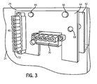
- FIG. 3 is a detailed perspective view of a component connector assembly installed on a rear panel of a component support
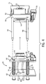
- FIG. 4 is side perspective view of the connector assemblies of FIGS. 2 and 3 prior to mating;
- FIG. 5 is a similar side view of the connector assemblies at the point of full engagement of the component support within the enclosure to force mating of the connector assemblies;
- FIG. 6 is a similar side perspective view of the connector assemblies positioned at a limit of the range of movement of the component connector assembly with respect to the prewired connector assembly;
- FIG. 7 is a perspective view of an alternative connector configuration for use in a component support including a single connector assembly
- FIG. 8 is a partial top view of the connector arrangement of FIG. 7;
- FIG. 9 is a partial side view of the connector arrangement of FIG. 8.
- FIG. 10 is a partial top view of the connector of FIG. 7 aligned for mating with a connector in a power, in a network and control power wireway.
- a packaged electrical system 10 is illustrated as including an enclosure 12 that houses various electrical components.
- the enclosure will typically be formed of heavy gage sheet metal, although other enclosures, such as made of reinforced plastic may sometimes be used.
- the enclosure generally forms a shell 14 having a main interior volume 16 in which components and component supports are placed.
- the interior volume 16 may be subdivided into compartments that each receive particular components, typically components interconnected to form a portion of the overall process control or monitoring system. Each compartment may be accessed through main doors 18.
- Latches 20 are provided to hold the doors closed over the interior volume during operation.
- component supports 24 may be disposed within each of the compartments, designated generally by reference numeral 22 in FIG. 1, component supports 24 may be disposed.
- the component supports 24 may be configured in various standard sizes or heights, and will typically comprise a metal drawer that can be slid into a compartment designed to accommodate the particular component support.
- components 26 are supported and interconnected.
- such components may include electronic devices, such as programmable logic controllers, power electronic devices, such as motor controllers, inverter drives, and so forth, as well as switchgear, input/output interfaces, protective circuit components, and so forth.
- the components are generally designed to perform some control or monitoring function within an overall machine system.
- data signals are exchanged with the components and remote control and monitoring equipment or computers (not shown).
- Power signals are also provided to the components, as described in greater detail below, for enabling energization of such components such as relays, contactors, and so forth.
- three phase power is typically provided to those components which will provide power to driven loads.
- loads may include motors, actuators, valves, and any other electrical load that may be present in the controlled or monitored process.
- a component connector assembly 28 is supported within each component support 24 .
- the component connector assembly 28 is disposed on a rear wall of the support.
- such component connector assemblies may be provided on any suitable surface or support of the component support, such as a side panel, a lower or upper corner, and so forth.
- the component connector assembly 28 will mate with a prewired connector assembly within the enclosure to provide network signals and control power to the components within the component support.
- the enclosure 12 is particularly configured to pass network signals and control power through routing pads separated from other paths for main or three phase power.
- an upper wireway or section 30 of the enclosure accommodates a network trunk cable 32 as well as conductors or cabling for control power, as indicated by reference numeral 34.
- the network trunk cable may be a shielded or flat media cable or any other suitable cable that is capable of transmitting data signals between the components and remote circuitry in accordance with standard network protocols.
- An exemplary protocol for MCCs for example, is the DeviceNet protocol.
- the control power supplied by conductors 34 may be provided at various levels, depending upon the application.
- the conductors may be particularly configured, for example, to carry 110, 115, 220 or 230 volt, single phase power, 24 volt direct current power, 24 volt single phase power, and so forth.
- a separate wireway 36 is provided in the enclosure for routing three phase power.
- power will be rated at 460 volt three phase, and may be provided in either three-wire configurations or four-wire configurations (including a neutral conductor).
- Such wiring will be routed through a main conduit 38 and connected within the backplane of the enclosure to main bus bars that are engaged by the component supports by conventional stab connections (not shown).
- FIG. 1 provides a separate network and control power wireway 40 isolated from the main power wireway 36. Because of the lower power levels that would typically be present in the network conductor 32 and control power conductors 34, it has been found desirable to separate these wireways for initial installation and subsequent servicing needs. Accordingly, a network cable 42 is provided in the network and control power wireway 40, and is electrically coupled to conductors within the trunk cable assembly 32. Similar drop conductors (not shown) are provided for conductors coupled to the control power conductors 34. Where multiple sections or bays are provided in the system, the network trunk cable assembly 32 and the control power conductors 34 may continue through similar wireways to such additional bays or enclosures. Tabs 44 are provided in the network and control power wireway 40 for accommodating prewired connector assemblies that mate with connector assembly 28 as described in greater detail below.
- FIG. 2 represents a detailed view of the rear wall of the enclosure of FIG. 1, showing the network and control wireway formed in a rear panel 46 of the enclosure.
- the wireway may be at least partially covered by blind plates 48 that enclose the wireway and are secured in place via appropriate fasteners to tabs 44.
- a prewired connector assembly 50 will be provided and similarly secured to the tabs of the wireway.
- Each prewired connector assembly generally includes a plate 52 on or through which a mating network connector 54 and a control power connector 56 are mounted.
- Connectors 54 and 56 may be of any suitable type or design.
- the mating network connector 54 includes an orientation-sensitive receptacle having four conductors, two for data signals and two for network power.
- the mating control power connector 56 is also a commercially available connector including multiple conductors in an orientation-sensitive body for conveying the appropriate level of control power (e.g., 110 or 115 volt single phase power, 24 volt direct current power, and so forth).
- the plate 52 also supports one or more alignment devices, such as alignment pins 58 in the illustrated embodiment. These alignment devices aid in aligning the mating connectors 54 and 56 with similar connectors of the component connector assembly as described in greater detail below.
- FIG. 3 illustrates an exemplary component connector assembly 28 of the type that can be interfaced with the prewired connector assembly 50 of FIG. 2.
- the component connector assembly 28 is mounted on a rear panel or wall 60 of the component support 24.
- a fixed base plate 62 is firmly secured to the rear wall, and connected to a connector support plate 64 that is moveable with respect to the base plate.
- Control or disengagement members 66 extend through the base plate 62 and are fixed (e.g., threaded) to the connector support plate 64 to force disengagement of the connectors as described in greater detail below.
- the plates include apertures or recesses 68 to accommodate the alignment pins 58 (see, FIG. 2) of the mating network connector to facilitate alignment of the connectors during engagement.
- a pair of separate connectors are supported on the connector support plate 64. These include a network connector 70 designed to mate with the mating network connector 54 shown in FIG. 2. Plate 64 also supports a control power connector 72 specifically designed to mate with connector 56 shown in FIG. 2.
- the prewired connector assembly 50 generally includes a network connector body 74 the connector face of which is the mating network connector 54.
- the network connector body 74 makes contact with conductors in the network cable 42 via insulation displacement ("vampire") pins (not shown).
- Vampire insulation displacement
- Other termination arrangements may, of course, be used.
- the connector assembly 28 includes both the network connector 70 and the control power connector 72 that are coupled to wiring or cables 80 that extend through apertures 76 and 78 in the base plate 62. Similar apertures will be provided in the rear panel of the component support to permit the passage of the cables 80.
- the connector support plate 64 with connectors 70 and 72 supported thereon is held in a biased position by compression springs 76 that are disposed on and around the control rods or pins 66.
- the control rods are slidable through apertures in the base plate 62 (and similar apertures in the rear panel of the component support) to allow compression of the springs 76.
- the springs hold the connector support plate 64 in a normal or operative position, but the combination of the springs and of the control rods 66 allow for movement of the connector support plate (and connectors 70 and 72) with respect to the rear panel of the component support.
- FIG. 5 illustrates the configuration of the connectors at the time of installation and full engagement of a component support.
- the springs 76 are compressed around the control rods 66, which are allowed to extend rearwardly through the base plate 62.
- the cables connected to connectors 70 and 72 are also free to move through the base plate.
- a force will be exerted on the connectors 70 and 72 to cause them to engage the respective connectors 54 and 56 of the prewired connector assembly. Thereafter, the components within the component support will be supplied with network signals and control power via the mated connector assemblies.
- FIG. 6 illustrates the mated connector assemblies in a retracted position of the component support (not shown in FIG. 6 for the sake of clarity).
- the base plate 62 of the component connector assembly is secured to the component support such that as the component support is partially withdrawn from the enclosure, the base plate 62 slides with respect to the control rods 66.
- the base plate 62 At a maximum point of withdrawal, effectively the limit of the range provided by the length of control rods 66, the base plate 62 will contact the heads of the control rods 66 and force disengagement of the connectors from one another.
- the range of movement provided in the component connector assembly 28 will depend essentially upon the distance desired for uncoupling main power from the component support (via withdrawal of stabs from power buses).
- the alternative connector assembly 82 of FIG. 7 includes a stationary part 84 designed to be affixed to the rear panel of a component support, and a movable part 86.
- the stationary part 84 has a flange 88 with fastener holes 90 designed to receive fasteners for fixing the stationary part on the rear panel (not shown in FIG. 7) of a component support.
- Guides 92 are formed on the movable part 86 to aid in guiding the movable part as it is slid within the stationary part.
- the guides 92 interface with recesses 94 for this purpose.
- the movable part 86 comprises a multi-pin plug 96 including either male, female or both types of engagement members for transmitting data signals to and from components within the component support, and for transmitting control power to the components.
- fore and aft movement of the movable part 86 is limited by a travel-limiting slot 100 in which a stop bolt 102 is positioned.
- the stop bolt 102 may be a shoulder fastener, for example, that is fitted to the movable part 86 through slot 100.
- one or more biasing springs indicated generally by reference numeral 104, serve to urge the movable part towards the operative or engaged position.
- an additional biasing member represented in FIGS. 8 and 9 may be included for interfacing with the movable part 86.
- a spring member 106 is provided that has a contour designed to interface with the head of the stop bolt 102. That is, in either the fully or near-fully retracted position or the fully or near-fully extended position, the spring member 106 generally causes a biasing force to be applied to the movable part 86 that can be overcome to allow the movable part to be slid into or out of the stationary part 84.
- FIG. 10 illustrates the alternative arrangement immediately prior to making of the connections.
- the movable part 86 of the alternative connector assembly 82 will generally be recessed within the stationary part 84.
- the stationary part 84 is, as noted above, secured to the rear panel of a component support as indicated by reference numeral 24.
- the bolt will bear against a rear surface of the travel-limiting slot 100.
- alignment pins 58 engage corresponding holes 98 (see FIG. 7) to align the connectors with one another. Further engagement of the component support within the enclosure, then, causes the connectors to be mated.
- the degree to which the component support can be withdrawn from the enclosure is, in the illustrated embodiment, defined by the length of the travel-limiting slot 100.
- the invention discloses a packaged electrical system including an enclosure and a main interior volume for component supports.
- the component supports may support electrical, electronic, power electronic and similar components, as well as switchgear and the like.
- a main power wireway is provided adjacent to the main interior volume of the enclosure for accommodating three phase power conductors.
- a network and control power wireway is formed separately from the main power wireway.
- the network and control power wireway may be formed toward the rear of the main interior volume, and may accommodate plug-in connections between component supports and network conductors and control power conductors. The network and control power wireway is thus accessible through a separate door from the main power wireway.
Landscapes
- Engineering & Computer Science (AREA)
- Power Engineering (AREA)
- Microelectronics & Electronic Packaging (AREA)
- Patch Boards (AREA)
- Details Of Connecting Devices For Male And Female Coupling (AREA)
Abstract
Description
- This application is a Continuation-In-Part of
U.S. Patent Application Serial No. 10/675,308 - The present invention relates generally to packaged electrical systems, and particularly to a technique for providing network signals and control power, separately from main power in such systems.
- A wide range of applications exist for packaged electrical systems, in settings from industry, to commercial applications and marine applications. In many such environments, electronic components, such as programmable logic controllers are packaged with power electronic components, such as motor drives, inverters, and so forth. The systems may further include input/output monitoring circuits, network interfaces, and the like. Most systems also include various types of protective circuitry, such as fuses and circuit breakers, along with switchgear, such as relays and contactors. These various components typically require network data exchange capabilities, along with control power supplies, such as for operation of the electric mechanical devices such as the relays and contactors. Main power is also provided, typically three phase alternating current power, that is ultimately provided to loads, such as motors.
- In conventional packaged electrical systems of the type described above, the components are arranged in one or more enclosures. The enclosures may be subdivided into compartments for associated circuit components. A wireway is typically provided on a side of the enclosure or the enclosure compartments that serves to route all power, network, and other conductors to the various compartments and components within the compartments.
- There is a need, however, for improved packaged systems that provide network signals, control power and main power to enclosed components. There is a particular need, for example, for systems that will enable separation of power levels so as to allow for servicing of the components and lower power-level conductors without accessing the main power conductors. Such arrangements are also needed that provide for hard-wiring of main power and plug-in connection of network conductors and control power conductors in a straightforward manner.
- The present invention provides a motor control center as an exemplary packaged electrical system designed to respond to such needs. The motor control center (MCC) generally includes an enclosure for housing a plurality of electrical power component supports. A network and control power wireway is configured to house conductors for a network link, as well as conductors for control power from a power source. A power wireway is also provided within the enclosure and separated from the network and control power wireway for housing three phase power conductors.
- In one exemplary arrangement, the network and control power wireway is disposed within a main interior volume of the enclosure. The main interior volume is accessible via at least one main door. The power wireway is formed within the enclosure adjacent to the main interior volume. The power wireway is accessible via a separate door, and is again separated from the network and control power wireway for routing of the three phase power conductors.
- The system may include prewired connector assemblies disposed over the network and power wireway. These connector assemblies can provide for plug-in engagement of component supports within the enclosure without accessing the power wireway.
- These and other features, aspects, and advantages of the present invention will become better understood when the following detailed description is read with reference to the accompanying drawings in which like characters represent like parts throughout the drawings, wherein:
- FIG. 1 is a perspective view of an exemplary packaged electrical system, such as an MCC, incorporating a connector arrangement in accordance with aspects of the invention;
- FIG. 2 is a detailed view of the prewired connector assembly installed in the enclosure of FIG. 1;
- FIG. 3 is a detailed perspective view of a component connector assembly installed on a rear panel of a component support;
- FIG. 4 is side perspective view of the connector assemblies of FIGS. 2 and 3 prior to mating;
- FIG. 5 is a similar side view of the connector assemblies at the point of full engagement of the component support within the enclosure to force mating of the connector assemblies; and
- FIG. 6 is a similar side perspective view of the connector assemblies positioned at a limit of the range of movement of the component connector assembly with respect to the prewired connector assembly;
- FIG. 7 is a perspective view of an alternative connector configuration for use in a component support including a single connector assembly;
- FIG. 8 is a partial top view of the connector arrangement of FIG. 7;
- FIG. 9 is a partial side view of the connector arrangement of FIG. 8; and
- FIG. 10 is a partial top view of the connector of FIG. 7 aligned for mating with a connector in a power, in a network and control power wireway.
- Turning now to the drawings, and referring first to FIG. 1, a packaged electrical system 10 is illustrated as including an
enclosure 12 that houses various electrical components. The enclosure will typically be formed of heavy gage sheet metal, although other enclosures, such as made of reinforced plastic may sometimes be used. The enclosure generally forms ashell 14 having a maininterior volume 16 in which components and component supports are placed. Theinterior volume 16 may be subdivided into compartments that each receive particular components, typically components interconnected to form a portion of the overall process control or monitoring system. Each compartment may be accessed throughmain doors 18.Latches 20 are provided to hold the doors closed over the interior volume during operation. - Within each of the compartments, designated generally by
reference numeral 22 in FIG. 1,component supports 24 may be disposed. As will be appreciated by those skilled in the art, the component supports 24 may be configured in various standard sizes or heights, and will typically comprise a metal drawer that can be slid into a compartment designed to accommodate the particular component support. On or within the component supports 24, a variety ofcomponents 26 are supported and interconnected. As noted above, such components may include electronic devices, such as programmable logic controllers, power electronic devices, such as motor controllers, inverter drives, and so forth, as well as switchgear, input/output interfaces, protective circuit components, and so forth. The components are generally designed to perform some control or monitoring function within an overall machine system. Accordingly, data signals are exchanged with the components and remote control and monitoring equipment or computers (not shown). Power signals are also provided to the components, as described in greater detail below, for enabling energization of such components such as relays, contactors, and so forth. Similarly, three phase power is typically provided to those components which will provide power to driven loads. Such loads may include motors, actuators, valves, and any other electrical load that may be present in the controlled or monitored process. - Within each
component support 24, acomponent connector assembly 28 is supported. In the illustrated embodiment, thecomponent connector assembly 28 is disposed on a rear wall of the support. As will be appreciated by those skilled in the art, such component connector assemblies may be provided on any suitable surface or support of the component support, such as a side panel, a lower or upper corner, and so forth. As described in greater detail below, thecomponent connector assembly 28 will mate with a prewired connector assembly within the enclosure to provide network signals and control power to the components within the component support. - The
enclosure 12 is particularly configured to pass network signals and control power through routing pads separated from other paths for main or three phase power. In the embodiment illustrated in FIG. 1, for example, an upper wireway orsection 30 of the enclosure accommodates anetwork trunk cable 32 as well as conductors or cabling for control power, as indicated by reference numeral 34. The network trunk cable may be a shielded or flat media cable or any other suitable cable that is capable of transmitting data signals between the components and remote circuitry in accordance with standard network protocols. An exemplary protocol for MCCs, for example, is the DeviceNet protocol. The control power supplied by conductors 34 may be provided at various levels, depending upon the application. The conductors may be particularly configured, for example, to carry 110, 115, 220 or 230 volt, single phase power, 24 volt direct current power, 24 volt single phase power, and so forth. - A
separate wireway 36 is provided in the enclosure for routing three phase power. In many applications, such power will be rated at 460 volt three phase, and may be provided in either three-wire configurations or four-wire configurations (including a neutral conductor). Such wiring will be routed through amain conduit 38 and connected within the backplane of the enclosure to main bus bars that are engaged by the component supports by conventional stab connections (not shown). - The embodiment shown in FIG. 1 provides a separate network and control
power wireway 40 isolated from themain power wireway 36. Because of the lower power levels that would typically be present in thenetwork conductor 32 and control power conductors 34, it has been found desirable to separate these wireways for initial installation and subsequent servicing needs. Accordingly, anetwork cable 42 is provided in the network and controlpower wireway 40, and is electrically coupled to conductors within thetrunk cable assembly 32. Similar drop conductors (not shown) are provided for conductors coupled to the control power conductors 34. Where multiple sections or bays are provided in the system, the networktrunk cable assembly 32 and the control power conductors 34 may continue through similar wireways to such additional bays or enclosures.Tabs 44 are provided in the network and controlpower wireway 40 for accommodating prewired connector assemblies that mate withconnector assembly 28 as described in greater detail below. - FIG. 2 represents a detailed view of the rear wall of the enclosure of FIG. 1, showing the network and control wireway formed in a
rear panel 46 of the enclosure. As shown in FIG. 2, the wireway may be at least partially covered byblind plates 48 that enclose the wireway and are secured in place via appropriate fasteners totabs 44. At the location of acomponent connector assembly 28 of a component support (see, FIG. 1), a prewiredconnector assembly 50 will be provided and similarly secured to the tabs of the wireway. Each prewired connector assembly generally includes aplate 52 on or through which amating network connector 54 and acontrol power connector 56 are mounted.Connectors mating network connector 54 includes an orientation-sensitive receptacle having four conductors, two for data signals and two for network power. The matingcontrol power connector 56 is also a commercially available connector including multiple conductors in an orientation-sensitive body for conveying the appropriate level of control power (e.g., 110 or 115 volt single phase power, 24 volt direct current power, and so forth). Theplate 52 also supports one or more alignment devices, such as alignment pins 58 in the illustrated embodiment. These alignment devices aid in aligning themating connectors - FIG. 3 illustrates an exemplary
component connector assembly 28 of the type that can be interfaced with the prewiredconnector assembly 50 of FIG. 2. In the particular implementation illustrated in FIG. 3, thecomponent connector assembly 28 is mounted on a rear panel orwall 60 of thecomponent support 24. A fixedbase plate 62 is firmly secured to the rear wall, and connected to aconnector support plate 64 that is moveable with respect to the base plate. Control ordisengagement members 66 extend through thebase plate 62 and are fixed (e.g., threaded) to theconnector support plate 64 to force disengagement of the connectors as described in greater detail below. The plates include apertures or recesses 68 to accommodate the alignment pins 58 (see, FIG. 2) of the mating network connector to facilitate alignment of the connectors during engagement. - In the embodiment illustrated in FIG. 3, a pair of separate connectors are supported on the
connector support plate 64. These include anetwork connector 70 designed to mate with themating network connector 54 shown in FIG. 2.Plate 64 also supports acontrol power connector 72 specifically designed to mate withconnector 56 shown in FIG. 2. - The connectors supported on the network and control power wireway and on the component support mate as illustrated in FIG. 4. As shown in FIG. 4, the prewired
connector assembly 50 generally includes anetwork connector body 74 the connector face of which is themating network connector 54. In the illustrated embodiment, thenetwork connector body 74 makes contact with conductors in thenetwork cable 42 via insulation displacement ("vampire") pins (not shown). Other termination arrangements may, of course, be used. - On the left-hand side of FIG. 4, the
component connector assembly 28 is illustrated, removed from the component support for the sake of clarity. Theconnector assembly 28 includes both thenetwork connector 70 and thecontrol power connector 72 that are coupled to wiring orcables 80 that extend throughapertures base plate 62. Similar apertures will be provided in the rear panel of the component support to permit the passage of thecables 80. Theconnector support plate 64 withconnectors springs 76. Thus, the springs hold theconnector support plate 64 in a normal or operative position, but the combination of the springs and of thecontrol rods 66 allow for movement of the connector support plate (andconnectors 70 and 72) with respect to the rear panel of the component support. - FIG. 5 illustrates the configuration of the connectors at the time of installation and full engagement of a component support. As can be seen in FIG. 5, the
springs 76 are compressed around thecontrol rods 66, which are allowed to extend rearwardly through thebase plate 62. The cables connected toconnectors connectors respective connectors - FIG. 6 illustrates the mated connector assemblies in a retracted position of the component support (not shown in FIG. 6 for the sake of clarity). Again, the
base plate 62 of the component connector assembly is secured to the component support such that as the component support is partially withdrawn from the enclosure, thebase plate 62 slides with respect to thecontrol rods 66. At a maximum point of withdrawal, effectively the limit of the range provided by the length ofcontrol rods 66, thebase plate 62 will contact the heads of thecontrol rods 66 and force disengagement of the connectors from one another. The range of movement provided in thecomponent connector assembly 28 will depend essentially upon the distance desired for uncoupling main power from the component support (via withdrawal of stabs from power buses). - As will be noted by those skilled in the art, once the connector assembly is described above are mated, contact between the connector assemblies is static. That is, no sliding contact takes place during either operation or during partial withdrawal for servicing of the component support from the enclosure. It has been found that such non-sliding contact between the connectors facilitates good signal transmission and avoids problems with signal degradation present in conventional sliding contacts for such applications.
- The foregoing arrangement allows for coupling of a component support to a connector for control power and network signals within a separated wireway using a connector assembly including more than one connector. An alternative configuration including a single connector is illustrated in FIG. 7. Although may such arrangements may be envisaged, the
alternative connector assembly 82 of FIG. 7 includes astationary part 84 designed to be affixed to the rear panel of a component support, and amovable part 86. Thestationary part 84 has aflange 88 withfastener holes 90 designed to receive fasteners for fixing the stationary part on the rear panel (not shown in FIG. 7) of a component support.Guides 92 are formed on themovable part 86 to aid in guiding the movable part as it is slid within the stationary part. Theguides 92 interface withrecesses 94 for this purpose. Themovable part 86 comprises amulti-pin plug 96 including either male, female or both types of engagement members for transmitting data signals to and from components within the component support, and for transmitting control power to the components. In the embodiment illustrated in FIG. 7, fore and aft movement of themovable part 86 is limited by a travel-limitingslot 100 in which astop bolt 102 is positioned. Thestop bolt 102 may be a shoulder fastener, for example, that is fitted to themovable part 86 throughslot 100. Within the assembly, one or more biasing springs, indicated generally byreference numeral 104, serve to urge the movable part towards the operative or engaged position. - Where desired, an additional biasing member represented in FIGS. 8 and 9 may be included for interfacing with the
movable part 86. In the illustrated embodiment, aspring member 106 is provided that has a contour designed to interface with the head of thestop bolt 102. That is, in either the fully or near-fully retracted position or the fully or near-fully extended position, thespring member 106 generally causes a biasing force to be applied to themovable part 86 that can be overcome to allow the movable part to be slid into or out of thestationary part 84. - FIG. 10 illustrates the alternative arrangement immediately prior to making of the connections. As shown in FIG. 10, the
movable part 86 of thealternative connector assembly 82 will generally be recessed within thestationary part 84. Thestationary part 84 is, as noted above, secured to the rear panel of a component support as indicated byreference numeral 24. In the stop bolt arrangement of the illustrated embodiment, the bolt will bear against a rear surface of the travel-limitingslot 100. As the connector assembly approaches the prewiredconnector assembly 50 provided within the network and controlpower wireway 40, alignment pins 58 engage corresponding holes 98 (see FIG. 7) to align the connectors with one another. Further engagement of the component support within the enclosure, then, causes the connectors to be mated. Thereafter, partial retraction of the component support is possible while maintaining a static (non-sliding) connection between the mated connectors. The degree to which the component support can be withdrawn from the enclosure is, in the illustrated embodiment, defined by the length of the travel-limitingslot 100. - While only certain features of the invention have been illustrated and described herein, many modifications and changes will occur to those skilled in the art. It is, therefore, to be understood that the appended claims are intended to cover all such modifications and changes as fall within the true spirit of the invention.
- In summary the invention discloses a packaged electrical system including an enclosure and a main interior volume for component supports. The component supports may support electrical, electronic, power electronic and similar components, as well as switchgear and the like. A main power wireway is provided adjacent to the main interior volume of the enclosure for accommodating three phase power conductors. A network and control power wireway is formed separately from the main power wireway. The network and control power wireway may be formed toward the rear of the main interior volume, and may accommodate plug-in connections between component supports and network conductors and control power conductors. The network and control power wireway is thus accessible through a separate door from the main power wireway.
Claims (7)
- A motor control center comprising:an enclosure for housing a plurality of electrical power component supports;a network and control power wireway within the enclosure and configured house conductors for a network link to the component supports and conductors for control power from a power source; anda power wireway within the enclosure and separated from the network and control power wireway for housing three phase power conductors.
- The system of claim 1, wherein the network and control power wireway is disposed along a rear portion of the enclosure.
- The system of claim 1 or 2, wherein the network and control power wireway is configured to receive a plurality of prewired connector assemblies for plug-in engagement of component supports within the enclosure.
- The system of any one of the preceding claims, wherein the control power conductors are configured to carry 110, 115, 220 or 230 volt, single phase power.
- The system of any one of the preceding claims, wherein the control power conductors are configured to carry 24 volt direct current or single phase power.
- The system of any one of the preceding claims, wherein the network and control power wireway is disposed within a main interior volume of the enclosure accessible via at least one main door, and the power wireway is disposed adjacent to the main interior volume of the enclosure and accessible via a separate door.
- The system of any one of the preceding claims, wherein network and control power wireway is disposed adjacent to an upper wireway, the upper wireway being configured to house a trunk network cable, and the network and control power wireway being configured to house a drop network cable coupled to the trunk network cable.
Applications Claiming Priority (1)
| Application Number | Priority Date | Filing Date | Title |
|---|---|---|---|
| US11/271,714 US7525809B2 (en) | 2003-09-30 | 2005-11-11 | Isolated control and network wireway for motor control center |
Publications (2)
| Publication Number | Publication Date |
|---|---|
| EP1786076A1 true EP1786076A1 (en) | 2007-05-16 |
| EP1786076B1 EP1786076B1 (en) | 2015-01-14 |
Family
ID=37837048
Family Applications (1)
| Application Number | Title | Priority Date | Filing Date |
|---|---|---|---|
| EP06023381.4A Ceased EP1786076B1 (en) | 2005-11-11 | 2006-11-09 | Isolated control and network wireway for motor control center |
Country Status (2)
| Country | Link |
|---|---|
| US (1) | US7525809B2 (en) |
| EP (1) | EP1786076B1 (en) |
Cited By (1)
| Publication number | Priority date | Publication date | Assignee | Title |
|---|---|---|---|---|
| RU2382459C1 (en) * | 2007-06-29 | 2010-02-20 | Андреас ЗИМЕС | Device for soft start control and shutdown of three-phase electric motors (soft starter) |
Families Citing this family (37)
| Publication number | Priority date | Publication date | Assignee | Title |
|---|---|---|---|---|
| US7688572B2 (en) * | 2006-07-26 | 2010-03-30 | Eaton Corporation | Motor control center subunit having moveable line contacts and method of manufacture |
| US10973143B2 (en) | 2006-07-26 | 2021-04-06 | Eaton Intelligent Power Limited | Coordinating installation and connection of a motor control center subunit having moveable line contacts |
| US8817454B2 (en) | 2006-07-26 | 2014-08-26 | Eaton Corporation | Coordinating installation and connection of a motor control center subunit having moveable line contacts |
| US7561412B2 (en) * | 2006-09-29 | 2009-07-14 | Rockwell Automation Technologies, Inc. | System and method for automatically securing a motor control center |
| US7528612B2 (en) * | 2006-09-29 | 2009-05-05 | Rockwell Automation Technologies, Inc. | System and method for monitoring a motor control center |
| US20080137266A1 (en) * | 2006-09-29 | 2008-06-12 | Rockwell Automation Technologies, Inc. | Motor control center with power and data distribution bus |
| DE202006015827U1 (en) * | 2006-10-16 | 2006-12-07 | Knürr AG | Power-bus bar system for casings and cupboards in information technology has a basic structure to conduct power and a module for distributing and supplying power |
| US8199022B2 (en) * | 2007-02-27 | 2012-06-12 | Eaton Corporation | Test module for motor control center subunit |
| US7808775B2 (en) * | 2008-03-07 | 2010-10-05 | Deere & Company | Modular power distribution system having a sealing arrangement for use in a work machine |
| WO2009117500A2 (en) * | 2008-03-19 | 2009-09-24 | Liebert Corporation | Adaptive power strip |
| US8054606B2 (en) * | 2008-06-10 | 2011-11-08 | Eaton Corporation | Remote operation of a motor control center subunit disconnect |
| US7800888B2 (en) * | 2008-11-13 | 2010-09-21 | Eaton Corporation | Motor control center subunit having visible contact disconnection and method of manufacture |
| KR101701922B1 (en) | 2009-11-17 | 2017-02-02 | 삼성전자 주식회사 | Docking apparatus for portable device |
| US8274782B2 (en) | 2010-09-30 | 2012-09-25 | Rockwell Automation Technologies, Inc. | Motor control center network connectivity method and system |
| US8952252B2 (en) | 2010-10-22 | 2015-02-10 | Rockwell Automation Technologies, Inc. | Arc resistant electrical enclosure |
| US20120127635A1 (en) * | 2010-11-18 | 2012-05-24 | Bruce William Grindeland | Modular Pump Control Panel Assembly |
| CN102759903B (en) | 2011-04-29 | 2017-03-01 | 洛克威尔自动控制技术股份有限公司 | Plug and play motor control system |
| US8964396B1 (en) * | 2012-04-11 | 2015-02-24 | Google Inc. | Rack power and data bus |
| US8810998B2 (en) * | 2012-04-23 | 2014-08-19 | Eaton Corporation | Motor control center and communication system therefor |
| ITMI20121280A1 (en) * | 2012-07-23 | 2014-01-24 | Campagnolo Srl | INVERTER OF COMMANDS FOR A COMMAND DEVICE FOR A BICYCLE CHANGE |
| CN103579850B (en) * | 2012-08-03 | 2016-06-08 | 台达电子工业股份有限公司 | Alignment device for power electronic device and its power module |
| US9160124B2 (en) | 2012-09-07 | 2015-10-13 | Apple Inc. | Compliant mount for connector |
| US8986029B2 (en) | 2012-09-11 | 2015-03-24 | Apple Inc. | Dock connector with compliance mechanism |
| US8721356B2 (en) * | 2012-09-11 | 2014-05-13 | Apple Inc. | Dock with compliant connector mount |
| US8988860B2 (en) * | 2012-11-29 | 2015-03-24 | Siemens Aktiengesellschaft | Power supplies having power electronic modules and replacement methods thereof |
| DE102013103443A1 (en) * | 2013-04-05 | 2014-10-09 | Eaton Industries (Austria) Gmbh | CABINET ASSEMBLY WITH CONNECTED PROTECTIVE AREAS |
| US8992241B2 (en) | 2013-04-30 | 2015-03-31 | International Business Machines Corporation | Flex circuit blind attachment apparatus and system |
| TWI507852B (en) * | 2013-10-29 | 2015-11-11 | Wistron Corp | Docking station and electronic apparatus |
| US9484657B2 (en) * | 2014-11-19 | 2016-11-01 | Tyco Electronics Corporation | Harness connector having a power and signal cartridges |
| US9926725B2 (en) * | 2015-01-22 | 2018-03-27 | Hubbell Incorporated | Lockable cover assembly |
| US9861002B1 (en) * | 2016-10-20 | 2018-01-02 | Rockwell Automation Technologies, Inc. | Single channel I/O in a modular sub-chassis |
| WO2020038604A1 (en) * | 2018-08-21 | 2020-02-27 | Eaton Intelligent Power Limited | Integrated direct mount branch protection for variable frequency drive |
| US11545826B2 (en) | 2019-06-28 | 2023-01-03 | Eaton Intelligent Power Limited | Electrical power distribution systems with a bypass unit that couples to a load and electrically engages one of two alternate units for powering the load and related methods |
| US11482911B2 (en) | 2019-06-28 | 2022-10-25 | Eaton Intelligent Power Limited | Electrical power distribution systems with a bypass unit that couples to a load and electrically engages one of two alternate units for powering the load and related methods |
| US20220167522A1 (en) * | 2020-11-25 | 2022-05-26 | Rich Slodkowski | Pre-cabled drawer system for computer networking equipment |
| US12160969B1 (en) * | 2022-01-12 | 2024-12-03 | ZT Group Int'l, Inc. | Adjustable card support |
| US12471230B2 (en) * | 2023-03-15 | 2025-11-11 | Eaton Intelligent Power Limited | Isolating motor control center bypass units and systems |
Citations (4)
| Publication number | Priority date | Publication date | Assignee | Title |
|---|---|---|---|---|
| US3626253A (en) * | 1970-05-06 | 1971-12-07 | Zinsco Electrical Products | Cell construction for motor control center for separate disengaging of terminal blocks and bus stabs |
| DE9204389U1 (en) * | 1992-03-31 | 1993-07-29 | Klöckner-Moeller GmbH, 53115 Bonn | Withdrawable low-voltage switchgear for supplying or distributing electrical energy |
| NL9201293A (en) * | 1992-07-17 | 1994-02-16 | Holec Syst & Componenten | Switching and distribution arrangement for centralized control of electric loads |
| DE4313653A1 (en) * | 1993-04-21 | 1994-10-27 | Siemens Ag | Low-voltage switchgear with a distribution board for several device carriers |
Family Cites Families (5)
| Publication number | Priority date | Publication date | Assignee | Title |
|---|---|---|---|---|
| US3641419A (en) * | 1970-02-06 | 1972-02-08 | Controlled Power Corp | Modular power supply with plural rectifier housings back of which contains rectifying devices, a transformer and fan means |
| US4121276A (en) * | 1976-12-30 | 1978-10-17 | Westinghouse Electric Corp. | Electrical switchboard apparatus with center fed vertical riser bus |
| US4733389A (en) * | 1986-07-28 | 1988-03-22 | Xerox Corporation | Drop cable for a local area network |
| US5295041A (en) * | 1992-07-31 | 1994-03-15 | Siemens Energy & Automation, Inc. | Modular construction distribution switchboard system cubicles with draw-out and fixed apparatus mounting flexibility |
| US5905631A (en) * | 1995-03-28 | 1999-05-18 | Klockner-Moeller Gmbh | Low-voltage switchgear assembly for the output or distribution of electrical energy |
-
2005
- 2005-11-11 US US11/271,714 patent/US7525809B2/en not_active Expired - Lifetime
-
2006
- 2006-11-09 EP EP06023381.4A patent/EP1786076B1/en not_active Ceased
Patent Citations (4)
| Publication number | Priority date | Publication date | Assignee | Title |
|---|---|---|---|---|
| US3626253A (en) * | 1970-05-06 | 1971-12-07 | Zinsco Electrical Products | Cell construction for motor control center for separate disengaging of terminal blocks and bus stabs |
| DE9204389U1 (en) * | 1992-03-31 | 1993-07-29 | Klöckner-Moeller GmbH, 53115 Bonn | Withdrawable low-voltage switchgear for supplying or distributing electrical energy |
| NL9201293A (en) * | 1992-07-17 | 1994-02-16 | Holec Syst & Componenten | Switching and distribution arrangement for centralized control of electric loads |
| DE4313653A1 (en) * | 1993-04-21 | 1994-10-27 | Siemens Ag | Low-voltage switchgear with a distribution board for several device carriers |
Cited By (1)
| Publication number | Priority date | Publication date | Assignee | Title |
|---|---|---|---|---|
| RU2382459C1 (en) * | 2007-06-29 | 2010-02-20 | Андреас ЗИМЕС | Device for soft start control and shutdown of three-phase electric motors (soft starter) |
Also Published As
| Publication number | Publication date |
|---|---|
| US20060063434A1 (en) | 2006-03-23 |
| US7525809B2 (en) | 2009-04-28 |
| EP1786076B1 (en) | 2015-01-14 |
Similar Documents
| Publication | Publication Date | Title |
|---|---|---|
| US7525809B2 (en) | Isolated control and network wireway for motor control center | |
| EP2276332B1 (en) | Electrical system having withdrawable unit with maintained control and communication connection | |
| US8638561B2 (en) | Motor control center unit withdraw with door closed | |
| US8553395B2 (en) | Motor control center network connectivity method and system | |
| EP1786070B1 (en) | Multiple height, high density horizontal low voltage motor control center | |
| EP1521511B1 (en) | Motor control center interconnection method and apparatus | |
| US9564707B2 (en) | Connection system with modular expansion units having two or more devices | |
| EP2693573A2 (en) | Power circuit electrical connection system and method | |
| EP3235103B1 (en) | Modular uninterruptible power supply and power distribution system | |
| US3394287A (en) | Frames for electrical communication apparatus | |
| US8602816B2 (en) | Connector device for electronic modules in automation systems | |
| WO2011156100A1 (en) | Power routing device for expansion slot of computer system | |
| EP3525303A1 (en) | Electrical unit for a motor control center with ingress protection | |
| US4352146A (en) | Rack structure for electrical communications equipment | |
| US12206191B2 (en) | Blind electrical connection in a motor control center through spring contacts | |
| US6893298B2 (en) | Device for connecting low-voltage devices | |
| EP1753110A1 (en) | Modular power distribution apparatus and methods with protective earth conductor | |
| CN105048198B (en) | A kind of input/output port, a kind of Train Control signal chassis and a kind of Train Control signal cabinet system |
Legal Events
| Date | Code | Title | Description |
|---|---|---|---|
| PUAI | Public reference made under article 153(3) epc to a published international application that has entered the european phase |
Free format text: ORIGINAL CODE: 0009012 |
|
| AK | Designated contracting states |
Kind code of ref document: A1 Designated state(s): AT BE BG CH CY CZ DE DK EE ES FI FR GB GR HU IE IS IT LI LT LU LV MC NL PL PT RO SE SI SK TR |
|
| AX | Request for extension of the european patent |
Extension state: AL BA HR MK YU |
|
| 17P | Request for examination filed |
Effective date: 20070821 |
|
| 17Q | First examination report despatched |
Effective date: 20070924 |
|
| AKX | Designation fees paid |
Designated state(s): DE FR GB IT |
|
| GRAP | Despatch of communication of intention to grant a patent |
Free format text: ORIGINAL CODE: EPIDOSNIGR1 |
|
| INTG | Intention to grant announced |
Effective date: 20141013 |
|
| GRAS | Grant fee paid |
Free format text: ORIGINAL CODE: EPIDOSNIGR3 |
|
| GRAA | (expected) grant |
Free format text: ORIGINAL CODE: 0009210 |
|
| AK | Designated contracting states |
Kind code of ref document: B1 Designated state(s): DE FR GB IT |
|
| REG | Reference to a national code |
Ref country code: GB Ref legal event code: FG4D |
|
| REG | Reference to a national code |
Ref country code: DE Ref legal event code: R096 Ref document number: 602006044302 Country of ref document: DE Effective date: 20150226 |
|
| REG | Reference to a national code |
Ref country code: DE Ref legal event code: R097 Ref document number: 602006044302 Country of ref document: DE |
|
| REG | Reference to a national code |
Ref country code: FR Ref legal event code: PLFP Year of fee payment: 10 |
|
| PLBE | No opposition filed within time limit |
Free format text: ORIGINAL CODE: 0009261 |
|
| STAA | Information on the status of an ep patent application or granted ep patent |
Free format text: STATUS: NO OPPOSITION FILED WITHIN TIME LIMIT |
|
| 26N | No opposition filed |
Effective date: 20151015 |
|
| REG | Reference to a national code |
Ref country code: FR Ref legal event code: PLFP Year of fee payment: 11 |
|
| REG | Reference to a national code |
Ref country code: FR Ref legal event code: PLFP Year of fee payment: 12 |
|
| P01 | Opt-out of the competence of the unified patent court (upc) registered |
Effective date: 20230404 |
|
| PGFP | Annual fee paid to national office [announced via postgrant information from national office to epo] |
Ref country code: GB Payment date: 20231019 Year of fee payment: 18 |
|
| PGFP | Annual fee paid to national office [announced via postgrant information from national office to epo] |
Ref country code: IT Payment date: 20231019 Year of fee payment: 18 Ref country code: FR Payment date: 20231019 Year of fee payment: 18 Ref country code: DE Payment date: 20231019 Year of fee payment: 18 |
|
| REG | Reference to a national code |
Ref country code: DE Ref legal event code: R119 Ref document number: 602006044302 Country of ref document: DE |
|
| GBPC | Gb: european patent ceased through non-payment of renewal fee |
Effective date: 20241109 |
|
| PG25 | Lapsed in a contracting state [announced via postgrant information from national office to epo] |
Ref country code: DE Free format text: LAPSE BECAUSE OF NON-PAYMENT OF DUE FEES Effective date: 20250603 |
|
| PG25 | Lapsed in a contracting state [announced via postgrant information from national office to epo] |
Ref country code: IT Free format text: LAPSE BECAUSE OF NON-PAYMENT OF DUE FEES Effective date: 20241109 |
|
| PG25 | Lapsed in a contracting state [announced via postgrant information from national office to epo] |
Ref country code: GB Free format text: LAPSE BECAUSE OF NON-PAYMENT OF DUE FEES Effective date: 20241109 |
|
| PG25 | Lapsed in a contracting state [announced via postgrant information from national office to epo] |
Ref country code: FR Free format text: LAPSE BECAUSE OF NON-PAYMENT OF DUE FEES Effective date: 20241130 |