EP1785775A1 - Image forming apparatus with a cleaning mechanism for a fixing device - Google Patents
Image forming apparatus with a cleaning mechanism for a fixing device Download PDFInfo
- Publication number
- EP1785775A1 EP1785775A1 EP06023332A EP06023332A EP1785775A1 EP 1785775 A1 EP1785775 A1 EP 1785775A1 EP 06023332 A EP06023332 A EP 06023332A EP 06023332 A EP06023332 A EP 06023332A EP 1785775 A1 EP1785775 A1 EP 1785775A1
- Authority
- EP
- European Patent Office
- Prior art keywords
- supply
- power
- cleaning operation
- cleaning
- image forming
- Prior art date
- Legal status (The legal status is an assumption and is not a legal conclusion. Google has not performed a legal analysis and makes no representation as to the accuracy of the status listed.)
- Granted
Links
Images




Classifications
-
- G—PHYSICS
- G03—PHOTOGRAPHY; CINEMATOGRAPHY; ANALOGOUS TECHNIQUES USING WAVES OTHER THAN OPTICAL WAVES; ELECTROGRAPHY; HOLOGRAPHY
- G03G—ELECTROGRAPHY; ELECTROPHOTOGRAPHY; MAGNETOGRAPHY
- G03G15/00—Apparatus for electrographic processes using a charge pattern
- G03G15/50—Machine control of apparatus for electrographic processes using a charge pattern, e.g. regulating differents parts of the machine, multimode copiers, microprocessor control
- G03G15/5004—Power supply control, e.g. power-saving mode, automatic power turn-off
-
- G—PHYSICS
- G03—PHOTOGRAPHY; CINEMATOGRAPHY; ANALOGOUS TECHNIQUES USING WAVES OTHER THAN OPTICAL WAVES; ELECTROGRAPHY; HOLOGRAPHY
- G03G—ELECTROGRAPHY; ELECTROPHOTOGRAPHY; MAGNETOGRAPHY
- G03G15/00—Apparatus for electrographic processes using a charge pattern
- G03G15/20—Apparatus for electrographic processes using a charge pattern for fixing, e.g. by using heat
- G03G15/2003—Apparatus for electrographic processes using a charge pattern for fixing, e.g. by using heat using heat
- G03G15/2014—Apparatus for electrographic processes using a charge pattern for fixing, e.g. by using heat using heat using contact heat
- G03G15/2017—Structural details of the fixing unit in general, e.g. cooling means, heat shielding means
- G03G15/2025—Structural details of the fixing unit in general, e.g. cooling means, heat shielding means with special means for lubricating and/or cleaning the fixing unit, e.g. applying offset preventing fluid
Definitions
- the present invention relates to a fixing device for use in a copier, facsimile apparatus, printer or similar electrophotographic image forming apparatus and more particularly to control over power supply for a cleaning mechanism configured to remove toner deposited on a heat roller included in a fixing device.
- a fixing device included in an image forming apparatus is configured to fix a toner image on a sheet or recording medium with a heat roller
- part of the toner image is not fixed on the sheet, but is deposited on a peeler adapted for peeling off the sheet from the heat roller.
- the toner thus deposited on the peeler is apt to form lumps and suddenly drop onto the heat roller, smearing successive sheets.
- the fixing device is usually provided with a cleaning mechanism for removing the toner deposited on the heat roller.
- An image forming apparatus for example, is required to immediately turn off power supply as soon as a printing operation ends after fixing a toner image on a sheet.
- the cleaning mechanism of the fixing device is configured to clean the heat roller after a printing operation, as stated previously, turning off power supply immediately after a printing operation causes the cleaning operation to be interrupted halfway or practically prevented from being executed.
- An image forming apparatus including a fixing device including a cleaning mechanism configured to collect toner left on a heat roller, of the present invention includes a deciding circuit for determining that a preselected number of prints are output after a printing job and a control unit for controlling a power-supply OFF operation in response to a power-supply OFF request.
- the control unit postpones the power-supply OFF operation indicated by the power-supply OFF request generated during the cleaning operation until the cleaning operation ends.
- the fixing device includes a heat roller 1 for fixing a toner image on a sheet or recording medium, a press roller for pressing the sheet against the heat roller 1 and a peeler 3 for peeling off the sheet from the heat roller 1.
- a cleaning roller 4 constitutes a cleaning mechanism for cleaning the surface of the heat roller 1.
- the problem with the above fixing device is that when toner on consecutive sheets, sequentially introduced in the fixing device, are deposited on the peeler 3 in a certain amount, it suddenly drops on the heat roller 1 in lumps and smears the following sheets, as stated previously. In light of this, the lumps of toner dropped from the peeler 3 on the heat roller 1 are collected by the cleaning roller or cleaning mechanism 4 by way of the press roller 2.
- FIG. 2 is a timing chart demonstrating the operation of an image forming apparatus, including the cleaning operation of the fixing unit shown in FIG. 1.
- the heat roller 1 is repeatedly turned on for a period of time of a and turned off for a period of time of b n consecutive times in order to physically cause toner deposited on the peeler 3, FIG. 1, to drop, and then the toner is collected by the cleaning roller 4 within a period of time of c during continuous rotation.
- the periods of time a , b and c and the number of times n may be variable in accordance with the cleaning effect.
- Such a cleaning operation should preferably be effected after a printing operation in order to guarantee expected print productivity.
- FIG. 3 is a flowchart showing the basic cleaning operation of the fixing device. As shown, when a printing operation is ended (YES, step S1), the fixing device is caused to effect a cleaning operation (step S2). If the printing operation is not ended (NO, step S1), then the procedure returns to the step S1.
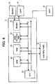
- FIG. 4 is a schematic block diagram showing an image forming apparatus with which the illustrative embodiments of the present invention are practicable.
- the image forming apparatus includes a control unit 11, a control panel 12, a sensor 13 and a load 14.
- the control unit 11 is connected to an external host 15 via a host interface not shown.
- the control unit 11 includes a CPU (Central Processing Unit) 21, a ROM 22 (Read Only Memory) storing a program for operating the CPU 21, a work RAM (Random Access Memory) 23 assigned to the program, a nonvolatile RAM 24 and an engine 25.
- the nonvolatile RAM 24 is adapted to store control, timing and other adjustment values and a registered copy mode and is capable of holding such data even when power supply is turned off.
- the engine 25 is configured to control the load 14 and so forth in accordance with the output of the sensor 13.
- a print counter for counting prints up to a preselected number is assigned to the nonvolatile RAM 24.
- the fixing device corresponds to the engine 25.
- FIG. 5 is a flowchart demonstrating the basic cleaning operation of the fixing device included in the image forming apparatus of the present invention.
- step S1 when a power-supply OFF request is generated (step S1), whether or not a cleaning operation is under way is determined (step S2). If a cleaning operation is not under way (NO, step S2), then power supply is turned off. If a cleaning operation is under way, (YES, step S2), the step S2 is repeated.
- FIG. 6 is a flowchart showing a cleaning operation executed in a fixing device included in a first embodiment of the present invention.
- a power-supply OFF command is generated while a cleaning operation is under way (YES, step S1)
- a suitable message e.g., "Cleaning” is displayed on the control panel 12 (step S2).
- step S2 a suitable message
- FIG. 7 is a flowchart showing a cleaning operation executed in a fixing device included in a second embodiment of the present invention.
- a printer driver e.g., a message "Cleaning" is displayed by use of a printer utility on the host 15 (step S2). This allows the user to confirm the current state of the image forming apparatus via a network, i.e., without actually moving to a position where the control panel 12 is visible.
- the object of the present invention is to cause the fixing device to surely perform a cleaning operation, so that power supply is basically not turned off while a cleaning operation is under way.
- FIG. 8 is a flowchart showing a cleaning operation executed in a fixing device included in a third embodiment of the present invention.
- a power-supply OFF request is generated (YES, step S2) while a cleaning operation is under way (step S1)
- step S3 whether or not the source of the request is an application is determined. If the source is an application and if it is a subject application (YES, step S3), the power-supply OFF request is accepted (step S4). If the answer of the step S2 is NO, then the cleaning operation is continued in the usual manner (steps S5 and S6).
- FIG. 9 is a flowchart showing a cleaning operation executed in a fixing device included in a fourth embodiment of the present invention. As shown, if a power-supply OFF request is generated by the user while a cleaning operation is under way (YES, steps S2 and S3), the request is accepted (step S4). If the answer of the step S2 is NO, then the cleaning operation is continued in the usual manner (steps S5 and S6).
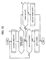
- FIG. 10 is a flowchart showing a cleaning operation executed in a fixing device included in a fourth embodiment of the present invention.
- a power-supply OFF request from the user may be sent via a network, it is difficult to arbitrate between a plurality of requests on a network.
- the illustrative embodiment limits a power-supply OFF request to a power key provided on the image forming apparatus.
- the power-supply OFF request is accepted (step S1, YES in step S2 and steps S3 and S4). If the answer of the step S2 is NO, then the cleaning operation is continued in the usual manner (steps S5 and S6).
- the present invention includes control means for causing, when a preselected number of prints are output after the end of a printing operation, the cleaning mechanism to clean the heat roller, and not accepting a power-supply OFF request generated during cleaning until the cleaning operation ends, thereby allowing the fixing device to surely execute the cleaning operation.
- control means causes and/or determines that a cleaning operation is necessary and/or to be executed when a blurred toner image is produced or after a crumpled sheet is outputted from the image forming apparatus, on which the image is produced.
- the invention further relates to the following embodiments which are parts of the description.
Landscapes
- Physics & Mathematics (AREA)
- General Physics & Mathematics (AREA)
- Engineering & Computer Science (AREA)
- Microelectronics & Electronic Packaging (AREA)
- Fixing For Electrophotography (AREA)
- Control Or Security For Electrophotography (AREA)
Abstract
Description
- The present invention relates to a fixing device for use in a copier, facsimile apparatus, printer or similar electrophotographic image forming apparatus and more particularly to control over power supply for a cleaning mechanism configured to remove toner deposited on a heat roller included in a fixing device.
- While a fixing device included in an image forming apparatus is configured to fix a toner image on a sheet or recording medium with a heat roller, it is likely that part of the toner image is not fixed on the sheet, but is deposited on a peeler adapted for peeling off the sheet from the heat roller. The toner thus deposited on the peeler is apt to form lumps and suddenly drop onto the heat roller, smearing successive sheets. In order to solve this problem, the fixing device is usually provided with a cleaning mechanism for removing the toner deposited on the heat roller.
- On the other hand, energy-saving schemes have recently been applied to various kinds of apparatuses in order to cope with environmental problems. An image forming apparatus, for example, is required to immediately turn off power supply as soon as a printing operation ends after fixing a toner image on a sheet. However, because the cleaning mechanism of the fixing device is configured to clean the heat roller after a printing operation, as stated previously, turning off power supply immediately after a printing operation causes the cleaning operation to be interrupted halfway or practically prevented from being executed.
- Technologies relating to the present invention are disclosed in, e.g.,
Japanese Patent Laid-Open Publication No. 07-104602 Japanese Patent No. 3,514,134 - It is an object of the present invention to provide a fixing device including a cleaning mechanism capable of surely cleaning a heat roller and an image forming apparatus including the same.
- It is another object of the present invention to provide a fixing device capable of controlling the ON/OFF of power supply for the above cleaning mechanism and an image forming apparatus including the same.
- An image forming apparatus, including a fixing device including a cleaning mechanism configured to collect toner left on a heat roller, of the present invention includes a deciding circuit for determining that a preselected number of prints are output after a printing job and a control unit for controlling a power-supply OFF operation in response to a power-supply OFF request. When the deciding circuit determines that a cleaning operation for the heat roller should be executed, the control unit postpones the power-supply OFF operation indicated by the power-supply OFF request generated during the cleaning operation until the cleaning operation ends.
- The above and other objects, features and advantages of the present invention will become more apparent from the following detailed description taken with the accompanying drawings in which:
- FIG. 1 is a view showing a fixing device included in an image forming apparatus to which the present invention is applied;
- FIG. 2 is a timing chart showing a specific cleaning operation of the fixing device shown in FIG. 1;
- FIG. 3 is a flowchart demonstrating a basic cleaning operation to be executed by the fixing device of FIG. 1;
- FIG. 4 is a view showing an image forming apparatus with which preferred embodiments of the present invention are practicable;
- FIG. 5 is a flowchart demonstrating a basic cleaning operation particular to the fixing device in accordance with the present invention; and
- FIGS. 6 through 10 are flowcharts showing specific cleaning procedures representative of a first to a fifth embodiment of the present invention.
- To better understand the present invention, a fixing device including a cleaning mechanism for cleaning a fixing roller will be described with reference to FIG. 1. As shown, the fixing device includes a
heat roller 1 for fixing a toner image on a sheet or recording medium, a press roller for pressing the sheet against theheat roller 1 and a peeler 3 for peeling off the sheet from theheat roller 1. A cleaning roller 4 constitutes a cleaning mechanism for cleaning the surface of theheat roller 1. - The problem with the above fixing device is that when toner on consecutive sheets, sequentially introduced in the fixing device, are deposited on the peeler 3 in a certain amount, it suddenly drops on the
heat roller 1 in lumps and smears the following sheets, as stated previously. In light of this, the lumps of toner dropped from the peeler 3 on theheat roller 1 are collected by the cleaning roller or cleaning mechanism 4 by way of thepress roller 2. - FIG. 2 is a timing chart demonstrating the operation of an image forming apparatus, including the cleaning operation of the fixing unit shown in FIG. 1. As shown, the
heat roller 1 is repeatedly turned on for a period of time of a and turned off for a period of time of b n consecutive times in order to physically cause toner deposited on the peeler 3, FIG. 1, to drop, and then the toner is collected by the cleaning roller 4 within a period of time of c during continuous rotation. The periods of time a, b and c and the number of times n may be variable in accordance with the cleaning effect. Such a cleaning operation should preferably be effected after a printing operation in order to guarantee expected print productivity. - FIG. 3 is a flowchart showing the basic cleaning operation of the fixing device. As shown, when a printing operation is ended (YES, step S1), the fixing device is caused to effect a cleaning operation (step S2). If the printing operation is not ended (NO, step S1), then the procedure returns to the step S1.
- In order to save energy, it is a common practice to turn off power supply as soon as a printing operation ends after the fixation of a toner image on a sheet. This brings about a problem that the operation of the cleaning mechanism assigned to the
heat roller 1 is interrupted or practically prevented from being executed. Preferred embodiments of the image forming apparatus in accordance with the present invention, which are free from the above problem, will be described hereinafter. - FIG. 4 is a schematic block diagram showing an image forming apparatus with which the illustrative embodiments of the present invention are practicable. As shown, the image forming apparatus includes a
control unit 11, acontrol panel 12, asensor 13 and aload 14. Thecontrol unit 11 is connected to anexternal host 15 via a host interface not shown. - The
control unit 11 includes a CPU (Central Processing Unit) 21, a ROM 22 (Read Only Memory) storing a program for operating theCPU 21, a work RAM (Random Access Memory) 23 assigned to the program, anonvolatile RAM 24 and anengine 25. Thenonvolatile RAM 24 is adapted to store control, timing and other adjustment values and a registered copy mode and is capable of holding such data even when power supply is turned off. Theengine 25 is configured to control theload 14 and so forth in accordance with the output of thesensor 13. A print counter for counting prints up to a preselected number is assigned to thenonvolatile RAM 24. The fixing device corresponds to theengine 25. - In the image forming apparatus having the above configuration, when a power-supply OFF request is generated while a cleaning operation is under way, power supply is not turned off until the cleaning operation ends so as not to degrade the cleaning effect.
- FIG. 5 is a flowchart demonstrating the basic cleaning operation of the fixing device included in the image forming apparatus of the present invention. As shown, when a power-supply OFF request is generated (step S1), whether or not a cleaning operation is under way is determined (step S2). If a cleaning operation is not under way (NO, step S2), then power supply is turned off. If a cleaning operation is under way, (YES, step S2), the step S2 is repeated.
- The illustrative embodiments of the image forming apparatus in accordance with the present invention will be described specifically hereinafter.
- FIG. 6 is a flowchart showing a cleaning operation executed in a fixing device included in a first embodiment of the present invention. As shown, when a power-supply OFF command is generated while a cleaning operation is under way (YES, step S1), a suitable message, e.g., "Cleaning" is displayed on the control panel 12 (step S2). Should power supply be not immediately turned off despite the generation of the power-supply OFF request, the operator would feel uneasy.
- FIG. 7 is a flowchart showing a cleaning operation executed in a fixing device included in a second embodiment of the present invention. As shown, when a cleaning operation is under way (YES, step S1), a printer driver, e.g., a message "Cleaning" is displayed by use of a printer utility on the host 15 (step S2). This allows the user to confirm the current state of the image forming apparatus via a network, i.e., without actually moving to a position where the
control panel 12 is visible. - The object of the present invention is to cause the fixing device to surely perform a cleaning operation, so that power supply is basically not turned off while a cleaning operation is under way. However, it is sometimes more practical to immediately stop a cleaning operation and turn off power supply in response to a power-supply OFF request. More specifically, because whether or not to accept the power-supply OFF request generated during cleaning is considered to be dependent on the source output the request, whether or not to accept the request may be determined in accordance with the source of the request, as will be described hereinafter.
- FIG. 8 is a flowchart showing a cleaning operation executed in a fixing device included in a third embodiment of the present invention. As shown, when a power-supply OFF request is generated (YES, step S2) while a cleaning operation is under way (step S1), whether or not the source of the request is an application is determined (step S3). If the source is an application and if it is a subject application (YES, step S3), the power-supply OFF request is accepted (step S4). If the answer of the step S2 is NO, then the cleaning operation is continued in the usual manner (steps S5 and S6).
- FIG. 9 is a flowchart showing a cleaning operation executed in a fixing device included in a fourth embodiment of the present invention. As shown, if a power-supply OFF request is generated by the user while a cleaning operation is under way (YES, steps S2 and S3), the request is accepted (step S4). If the answer of the step S2 is NO, then the cleaning operation is continued in the usual manner (steps S5 and S6).
- FIG. 10 is a flowchart showing a cleaning operation executed in a fixing device included in a fourth embodiment of the present invention. Generally, although a power-supply OFF request from the user may be sent via a network, it is difficult to arbitrate between a plurality of requests on a network. In light of this, the illustrative embodiment limits a power-supply OFF request to a power key provided on the image forming apparatus. As shown in FIG. 10, when the power key is in an OFF state, the power-supply OFF request is accepted (step S1, YES in step S2 and steps S3 and S4). If the answer of the step S2 is NO, then the cleaning operation is continued in the usual manner (steps S5 and S6).
- In summary, in an image forming apparatus including a fixing device in which a cleaning mechanism for collecting toner left on a heat roller is arranged, the present invention includes control means for causing, when a preselected number of prints are output after the end of a printing operation, the cleaning mechanism to clean the heat roller, and not accepting a power-supply OFF request generated during cleaning until the cleaning operation ends, thereby allowing the fixing device to surely execute the cleaning operation.
- Alternatively, the control means causes and/or determines that a cleaning operation is necessary and/or to be executed when a blurred toner image is produced or after a crumpled sheet is outputted from the image forming apparatus, on which the image is produced.
- The invention further relates to the following embodiments which are parts of the description.
- Advantageous features of different embodiments can be combined with each other in one embodiment. It is further possible to omit one or more features from a specific embodiment.
- The omitted one or more features are not necessary for the specific embodiment.
- Preferred embodiments and/or features of the invention are indicated as follows:
- 1. An image forming apparatus including a fixing device including a cleaning mechanism configured to collect toner left on a heat roller, said image forming apparatus comprising:
- deciding means for determining that a preselected number of prints are output after a printing job; and
- control means for controlling a power-supply OFF operation in response to a power-supply OFF request;
- 2. The apparatus as indicated in embodiment no.1, wherein said control means displays on a control panel a message showing that the cleaning operation is under way.
- 3. The apparatus as indicated in embodiment no. 1, wherein said control means causes an external host to display a message showing that the cleaning operation is under way.
- 4. The apparatus as indicated in embodiment no.1, 2 or 3, wherein said control means determines whether or not to postpone the power-supply OFF operation in dependence on a source generated the power-supply OFF request.
- 5. The apparatus as indicated in any one of embodiments no. 1 to 4, wherein the deciding means is a deciding circuit, and the control means is a control unit.
- 6. An image forming apparatus including a fixing device including a cleaning mechanism configured to collect toner left on a heat roller, said image forming apparatus comprising:
- a deciding circuit configured to determine that a preselected number of prints are output after a printing job; and
- a control unit configured to control a power-supply OFF operation in response to a power-supply OFF request;
- 7. The apparatus as indicated in embodiment no. 6, wherein said control unit displays on a control panel a message showing that the cleaning operation is under way.
- 8. The apparatus as indicated in embodiment no. 6, wherein said control unit causes an external host to display a message showing that the cleaning operation is under way.
- 9. The apparatus as indicated in embodiment no. 6, 7 or 8, wherein said control unit determines whether or not to postpone the power-supply OFF operation in dependence on a source generated the power-supply OFF request.
- A further preferred embodiment and/or advantageous features of the invention are indicated as follows:
- An image forming apparatus of the present invention includes a fixing device in which a cleaning mechanism for collecting toner left on a heat roller is arranged. When a preselected number of prints are output after the end of a printing job, a cleaning operation for cleaning the heat roller is executed. When a power-supply OFF request arrives while the cleaning operation is under way, a power-supply OFF operation is postponed until the cleaning operation ends.
End of the description.
Claims (13)
- An image forming apparatus including a fixing device including a cleaning mechanism (4) configured to collect toner left on a heat roller (1), said image forming apparatus comprising:a deciding means configured to determine whether or not a cleaning operation for the heat roller (1) is to be executed; anda control means (11) configured to control a power-supply OFF operation in response to a power-supply OFF request;wherein said control means (11) postpones, when said deciding means (21) determines that the cleaning operation for the heat roller (1) should be executed, the power-supply OFF operation indicated by the power-supply OFF request generated during the cleaning operation until said cleaning operation ends.
- The apparatus as claimed in claim 1, wherein said control means (11) displays on a control panel (12) a message showing that the cleaning operation is under way.
- The apparatus as claimed in claim 1 or 2, wherein said control means (11) causes an external host (15) to display a message showing that the cleaning operation is under way.
- The apparatus as claimed in any one of claim 1 to 3, wherein said control means (11) determines whether or not to postpone the power-supply OFF operation in dependence on a source generated the power-supply OFF request.
- The apparatus as claimed in any one of claims 1 to 4, wherein the deciding means is
a deciding circuitand wherein the control means (21) is
a control unit (21). - The apparatus as claimed in any one of claims 1 to 5, wherein the deciding means is configured to determine that a preselected number of prints are outputted after a printing job.
- The apparatus as claimed in any one of claims 1 to 5, wherein the deciding means is configured to determine that a cleaning operation is to be executed when a blurred toner image is produced or after a crumpled sheet is outputted from the image forming apparatus, on which an image is produced.
- A method for controlling a power-supply OFF operation of an image forming apparatus, the method comprises the following steps:a) determining whether or not a cleaning operation for a heat roller (1) of a fixing device of the image forming apparatus is to be executed; andb) controlling a power-supply OFF operation in response to a power-supply OFF request;c) postponing the power-supply OFF operation indicated by the power-supply OFF request generated during the cleaning operation until said cleaning operation ends, when in the step a) it is determined that the cleaning operation for the heat roller (1) should be executed.
- The method as claimed in claim 8, further comprising the following step:d) displaying (Fig. 6, S2) on a control panel (12) a message showing that the cleaning operation is under-way.
- The method as claimed in claim 8, further comprising the following step:d) causing (Fig. 7, S2) an external host (15) to display a message showing that the cleaning operation is under way.
- The method as claimed in any one of claims 8 to 10, wherein the method further comprises:determining whether or not to postpone the power-supply OFF operation in dependence on a source generated the power-supply OFF request.
- The method as claimed in any one of claims 8 to 11, wherein in step a) it is determined that a preselected number of prints are outputted after a printing job.
- The method as claimed in any one of claims 8 to 11, wherein in step a) it is determined that a cleaning operation is to be executed when a blurred toner image is produced or after a crumbled sheet is outputted from the image forming apparatus, on which an image is produced.
Applications Claiming Priority (1)
| Application Number | Priority Date | Filing Date | Title |
|---|---|---|---|
| JP2005328175A JP2007133269A (en) | 2005-11-11 | 2005-11-11 | Image forming apparatus |
Publications (2)
| Publication Number | Publication Date |
|---|---|
| EP1785775A1 true EP1785775A1 (en) | 2007-05-16 |
| EP1785775B1 EP1785775B1 (en) | 2008-07-23 |
Family
ID=37806790
Family Applications (1)
| Application Number | Title | Priority Date | Filing Date |
|---|---|---|---|
| EP06023332A Not-in-force EP1785775B1 (en) | 2005-11-11 | 2006-11-09 | Image forming apparatus with a cleaning mechanism for a fixing device |
Country Status (4)
| Country | Link |
|---|---|
| US (1) | US7657215B2 (en) |
| EP (1) | EP1785775B1 (en) |
| JP (1) | JP2007133269A (en) |
| DE (1) | DE602006001923D1 (en) |
Families Citing this family (4)
| Publication number | Priority date | Publication date | Assignee | Title |
|---|---|---|---|---|
| JP5353343B2 (en) * | 2009-03-17 | 2013-11-27 | 株式会社リコー | Fixing apparatus and image forming apparatus |
| JP5440348B2 (en) * | 2010-04-16 | 2014-03-12 | コニカミノルタ株式会社 | Fixing apparatus and image forming apparatus |
| JP5625843B2 (en) * | 2010-12-08 | 2014-11-19 | 株式会社リコー | Image processing apparatus and image processing apparatus control method |
| JP6995521B2 (en) * | 2017-07-14 | 2022-01-14 | キヤノン株式会社 | Image forming device |
Citations (4)
| Publication number | Priority date | Publication date | Assignee | Title |
|---|---|---|---|---|
| JPH03171184A (en) * | 1989-11-30 | 1991-07-24 | Copal Electron Co Ltd | Automatic power-off mechanism for wet developing system image forming device |
| EP0892322A2 (en) * | 1997-07-14 | 1999-01-20 | Canon Kabushiki Kaisha | Fixing apparatus having cleaning mode and storage medium storing program therefor |
| US5865121A (en) * | 1998-01-29 | 1999-02-02 | Hewlett-Packard Company | System for cleaning rollers in an image forming device |
| US6181890B1 (en) * | 1998-07-30 | 2001-01-30 | Canon Kabushiki Kaisha | Image forming apparatus having a cleaning operation for a fixing device |
Family Cites Families (11)
| Publication number | Priority date | Publication date | Assignee | Title |
|---|---|---|---|---|
| JP3201796B2 (en) | 1991-10-31 | 2001-08-27 | 株式会社リコー | Image forming device |
| JPH06183055A (en) | 1992-12-19 | 1994-07-05 | Ricoh Co Ltd | Image forming device |
| JPH07104602A (en) | 1993-10-06 | 1995-04-21 | Konica Corp | Fixing device provided with cleaning member |
| JP3514134B2 (en) | 1998-08-31 | 2004-03-31 | 富士ゼロックス株式会社 | Cleaning device and image forming device |
| JP3171184B2 (en) | 1999-06-07 | 2001-05-28 | 松下電器産業株式会社 | Heat drying device and heat drying method |
| US6385412B1 (en) * | 2000-11-28 | 2002-05-07 | Toshiba Tec Kabushiki Kaisha | Image forming apparatus |
| JP2002244473A (en) * | 2001-02-14 | 2002-08-30 | Canon Inc | Fixing device and image forming device equipped therewith |
| US6991308B2 (en) | 2001-12-12 | 2006-01-31 | Ricoh Company, Ltd. | Image formation device, process cartridge initializing method, and process cartridge initializing program |
| JP2005107507A (en) | 2003-09-12 | 2005-04-21 | Ricoh Co Ltd | Image forming apparatus |
| US7299001B2 (en) | 2003-09-12 | 2007-11-20 | Ricoh Company, Ltd. | Fuser cleaning method and system in image-forming device |
| JP4537215B2 (en) * | 2004-02-03 | 2010-09-01 | キヤノン株式会社 | Image heating device |
-
2005
- 2005-11-11 JP JP2005328175A patent/JP2007133269A/en active Pending
-
2006
- 2006-11-09 US US11/594,997 patent/US7657215B2/en not_active Expired - Fee Related
- 2006-11-09 EP EP06023332A patent/EP1785775B1/en not_active Not-in-force
- 2006-11-09 DE DE602006001923T patent/DE602006001923D1/en active Active
Patent Citations (4)
| Publication number | Priority date | Publication date | Assignee | Title |
|---|---|---|---|---|
| JPH03171184A (en) * | 1989-11-30 | 1991-07-24 | Copal Electron Co Ltd | Automatic power-off mechanism for wet developing system image forming device |
| EP0892322A2 (en) * | 1997-07-14 | 1999-01-20 | Canon Kabushiki Kaisha | Fixing apparatus having cleaning mode and storage medium storing program therefor |
| US5865121A (en) * | 1998-01-29 | 1999-02-02 | Hewlett-Packard Company | System for cleaning rollers in an image forming device |
| US6181890B1 (en) * | 1998-07-30 | 2001-01-30 | Canon Kabushiki Kaisha | Image forming apparatus having a cleaning operation for a fixing device |
Also Published As
| Publication number | Publication date |
|---|---|
| DE602006001923D1 (en) | 2008-09-04 |
| US20070116500A1 (en) | 2007-05-24 |
| US7657215B2 (en) | 2010-02-02 |
| JP2007133269A (en) | 2007-05-31 |
| EP1785775B1 (en) | 2008-07-23 |
Similar Documents
| Publication | Publication Date | Title |
|---|---|---|
| US8488169B2 (en) | Information equipment and image forming apparatus effectively displaying specific information and method of display | |
| JPH11341212A5 (en) | ||
| JP2002312148A (en) | Printing system | |
| JP3609911B2 (en) | Image forming system | |
| EP1785775B1 (en) | Image forming apparatus with a cleaning mechanism for a fixing device | |
| JP2005119203A (en) | Image processing apparatus and image processing method | |
| JP2006301016A (en) | Billing management apparatus, billing management method, billing management program | |
| JP3758829B2 (en) | Printing system | |
| US20080049255A1 (en) | Printing apparatus and control method thereof | |
| EP3792696B1 (en) | Image forming apparatus and method of controlling the image forming apparatus | |
| JP2006123476A (en) | Printing apparatus, printing control method, printing control program, and recording medium for recording printing control program | |
| JP3882393B2 (en) | Method and apparatus for controlling image forming apparatus | |
| JP2006330477A (en) | Image forming system, image forming apparatus, and image forming method | |
| US7193737B2 (en) | Method of storing initial use date of printer and informing the date | |
| JP2007001080A (en) | Printer | |
| US20250211685A1 (en) | Co2 emissions estimation system and non-transitory computer-readable recording medium with co2 emissions estimation program stored thereon | |
| JP2004299242A (en) | Printer device | |
| JP2025172524A (en) | Printing device, printing device control method, and program | |
| JP2002373073A (en) | Printing equipment | |
| JP2000229451A (en) | Method and apparatus for printer control | |
| JP2000298559A (en) | Printer driver | |
| JP4525179B2 (en) | Print control apparatus and program | |
| JP2025147747A (en) | Information processing system and information processing program | |
| JP5609276B2 (en) | Image forming apparatus and power consumption display method thereof | |
| CN120612138A (en) | Information processing system, program product, and information processing method |
Legal Events
| Date | Code | Title | Description |
|---|---|---|---|
| PUAI | Public reference made under article 153(3) epc to a published international application that has entered the european phase |
Free format text: ORIGINAL CODE: 0009012 |
|
| 17P | Request for examination filed |
Effective date: 20061109 |
|
| AK | Designated contracting states |
Kind code of ref document: A1 Designated state(s): AT BE BG CH CY CZ DE DK EE ES FI FR GB GR HU IE IS IT LI LT LU LV MC NL PL PT RO SE SI SK TR |
|
| AX | Request for extension of the european patent |
Extension state: AL BA HR MK YU |
|
| AKX | Designation fees paid |
Designated state(s): DE ES FR GB IT NL |
|
| GRAP | Despatch of communication of intention to grant a patent |
Free format text: ORIGINAL CODE: EPIDOSNIGR1 |
|
| GRAS | Grant fee paid |
Free format text: ORIGINAL CODE: EPIDOSNIGR3 |
|
| GRAA | (expected) grant |
Free format text: ORIGINAL CODE: 0009210 |
|
| AK | Designated contracting states |
Kind code of ref document: B1 Designated state(s): DE ES FR GB IT NL |
|
| REG | Reference to a national code |
Ref country code: GB Ref legal event code: FG4D |
|
| REF | Corresponds to: |
Ref document number: 602006001923 Country of ref document: DE Date of ref document: 20080904 Kind code of ref document: P |
|
| NLV1 | Nl: lapsed or annulled due to failure to fulfill the requirements of art. 29p and 29m of the patents act | ||
| PG25 | Lapsed in a contracting state [announced via postgrant information from national office to epo] |
Ref country code: NL Free format text: LAPSE BECAUSE OF FAILURE TO SUBMIT A TRANSLATION OF THE DESCRIPTION OR TO PAY THE FEE WITHIN THE PRESCRIBED TIME-LIMIT Effective date: 20080723 |
|
| PG25 | Lapsed in a contracting state [announced via postgrant information from national office to epo] |
Ref country code: ES Free format text: LAPSE BECAUSE OF FAILURE TO SUBMIT A TRANSLATION OF THE DESCRIPTION OR TO PAY THE FEE WITHIN THE PRESCRIBED TIME-LIMIT Effective date: 20081103 |
|
| PLBE | No opposition filed within time limit |
Free format text: ORIGINAL CODE: 0009261 |
|
| STAA | Information on the status of an ep patent application or granted ep patent |
Free format text: STATUS: NO OPPOSITION FILED WITHIN TIME LIMIT |
|
| 26N | No opposition filed |
Effective date: 20090424 |
|
| PG25 | Lapsed in a contracting state [announced via postgrant information from national office to epo] |
Ref country code: IT Free format text: LAPSE BECAUSE OF FAILURE TO SUBMIT A TRANSLATION OF THE DESCRIPTION OR TO PAY THE FEE WITHIN THE PRESCRIBED TIME-LIMIT Effective date: 20080723 |
|
| PGFP | Annual fee paid to national office [announced via postgrant information from national office to epo] |
Ref country code: DE Payment date: 20131121 Year of fee payment: 8 Ref country code: GB Payment date: 20131120 Year of fee payment: 8 Ref country code: FR Payment date: 20131120 Year of fee payment: 8 |
|
| REG | Reference to a national code |
Ref country code: DE Ref legal event code: R119 Ref document number: 602006001923 Country of ref document: DE |
|
| GBPC | Gb: european patent ceased through non-payment of renewal fee |
Effective date: 20141109 |
|
| REG | Reference to a national code |
Ref country code: FR Ref legal event code: ST Effective date: 20150731 |
|
| PG25 | Lapsed in a contracting state [announced via postgrant information from national office to epo] |
Ref country code: DE Free format text: LAPSE BECAUSE OF NON-PAYMENT OF DUE FEES Effective date: 20150602 Ref country code: GB Free format text: LAPSE BECAUSE OF NON-PAYMENT OF DUE FEES Effective date: 20141109 |
|
| PG25 | Lapsed in a contracting state [announced via postgrant information from national office to epo] |
Ref country code: FR Free format text: LAPSE BECAUSE OF NON-PAYMENT OF DUE FEES Effective date: 20141201 |