EP1785617A1 - Gas turbine engine with power transfer and method - Google Patents
Gas turbine engine with power transfer and method Download PDFInfo
- Publication number
- EP1785617A1 EP1785617A1 EP06255643A EP06255643A EP1785617A1 EP 1785617 A1 EP1785617 A1 EP 1785617A1 EP 06255643 A EP06255643 A EP 06255643A EP 06255643 A EP06255643 A EP 06255643A EP 1785617 A1 EP1785617 A1 EP 1785617A1
- Authority
- EP
- European Patent Office
- Prior art keywords
- engine
- gas turbine
- gas
- gas path
- turbine engine
- Prior art date
- Legal status (The legal status is an assumption and is not a legal conclusion. Google has not performed a legal analysis and makes no representation as to the accuracy of the status listed.)
- Granted
Links
Images


Classifications
-
- F—MECHANICAL ENGINEERING; LIGHTING; HEATING; WEAPONS; BLASTING
- F01—MACHINES OR ENGINES IN GENERAL; ENGINE PLANTS IN GENERAL; STEAM ENGINES
- F01D—NON-POSITIVE DISPLACEMENT MACHINES OR ENGINES, e.g. STEAM TURBINES
- F01D15/00—Adaptations of machines or engines for special use; Combinations of engines with devices driven thereby
- F01D15/10—Adaptations for driving, or combinations with, electric generators
-
- F—MECHANICAL ENGINEERING; LIGHTING; HEATING; WEAPONS; BLASTING
- F02—COMBUSTION ENGINES; HOT-GAS OR COMBUSTION-PRODUCT ENGINE PLANTS
- F02C—GAS-TURBINE PLANTS; AIR INTAKES FOR JET-PROPULSION PLANTS; CONTROLLING FUEL SUPPLY IN AIR-BREATHING JET-PROPULSION PLANTS
- F02C1/00—Gas-turbine plants characterised by the use of hot gases or unheated pressurised gases, as the working fluid
- F02C1/04—Gas-turbine plants characterised by the use of hot gases or unheated pressurised gases, as the working fluid the working fluid being heated indirectly
-
- F—MECHANICAL ENGINEERING; LIGHTING; HEATING; WEAPONS; BLASTING
- F02—COMBUSTION ENGINES; HOT-GAS OR COMBUSTION-PRODUCT ENGINE PLANTS
- F02K—JET-PROPULSION PLANTS
- F02K3/00—Plants including a gas turbine driving a compressor or a ducted fan
- F02K3/02—Plants including a gas turbine driving a compressor or a ducted fan in which part of the working fluid by-passes the turbine and combustion chamber
- F02K3/04—Plants including a gas turbine driving a compressor or a ducted fan in which part of the working fluid by-passes the turbine and combustion chamber the plant including ducted fans, i.e. fans with high volume, low pressure outputs, for augmenting the jet thrust, e.g. of double-flow type
- F02K3/06—Plants including a gas turbine driving a compressor or a ducted fan in which part of the working fluid by-passes the turbine and combustion chamber the plant including ducted fans, i.e. fans with high volume, low pressure outputs, for augmenting the jet thrust, e.g. of double-flow type with front fan
-
- F—MECHANICAL ENGINEERING; LIGHTING; HEATING; WEAPONS; BLASTING
- F02—COMBUSTION ENGINES; HOT-GAS OR COMBUSTION-PRODUCT ENGINE PLANTS
- F02K—JET-PROPULSION PLANTS
- F02K3/00—Plants including a gas turbine driving a compressor or a ducted fan
- F02K3/08—Plants including a gas turbine driving a compressor or a ducted fan with supplementary heating of the working fluid; Control thereof
- F02K3/105—Heating the by-pass flow
- F02K3/115—Heating the by-pass flow by means of indirect heat exchange
-
- Y—GENERAL TAGGING OF NEW TECHNOLOGICAL DEVELOPMENTS; GENERAL TAGGING OF CROSS-SECTIONAL TECHNOLOGIES SPANNING OVER SEVERAL SECTIONS OF THE IPC; TECHNICAL SUBJECTS COVERED BY FORMER USPC CROSS-REFERENCE ART COLLECTIONS [XRACs] AND DIGESTS
- Y02—TECHNOLOGIES OR APPLICATIONS FOR MITIGATION OR ADAPTATION AGAINST CLIMATE CHANGE
- Y02T—CLIMATE CHANGE MITIGATION TECHNOLOGIES RELATED TO TRANSPORTATION
- Y02T50/00—Aeronautics or air transport
- Y02T50/60—Efficient propulsion technologies, e.g. for aircraft
Definitions
- the fan 12 is driven by a turbine, namely the low pressure (LP) turbine 22, via a shaft 26 (sometimes called the fan shaft).
- a turbine namely the low pressure (LP) turbine 22
- LP shaft 26 sometimes called the fan shaft.
- the fan 12, LP turbine 22 and LP shaft 26 together form a unit within the engine 10 which unit is sometimes referred to as the LP spool, which may also optionally include an LP compressor in addition to the fan 12.
- FIGS. 1 and 2 further show an electrical generator 32 mounted to the LP shaft 26 in order to transform torque therefrom into electrical power.
- the illustrated embodiment shows the electrical generator 32 being coaxially mounted on the LP shaft 26.
- Other ways of connecting the electrical generator 32 can be chosen, depending on the engine.
- This electrical generator 32 is electrically connected to one or more electrical heaters 34, 36 located around the core gas path and the by-pass gas path, respectively such that heat developed by the heaters is transferred to the gas in the gas path.
- Heaters 34 and 36 are preferably resistive heaters which are provided to surround the annular gas path. The heaters are adapted to, when activated, heat the air or gas passing through the associated section of gas path, as will be discussed further below.
- One or more electrical heaters 36 can be provided in the by-pass passage 20 at a suitable location, preferably towards the downstream end of the by-pass duct is preferred.
- heater(s) 34 when heater(s) 34 is activated in the core gas path in the region of the combustor 16 of the engine, the heat added by the heater heats the air/gas flows passing therethrough and into the HP turbine 24, and thus has the effect as if added fuel has been burned in the combustor 16 (i.e. the combustion gases are hotter than they otherwise would have been without using more fuel at the combustor 16), and thus more thermal energy is provided to the gas flow for subsequent power extraction by the HP turbine 24.
- the added heat can also be used to reduce the amount of fuel supplied to the combustor 16 to attain a specific gas temperature.
- heater 34 is driven by generator 32 on the LP spool, the apparatus can be employed such that torque developed by the LP turbine 22 can be partially returned to the HP turbine 24. Since resistive electrical heaters 34, 36 are very efficient at converting electrical power into heat and since turbines 22, 24 are also highly efficient, the overall efficiency of the power transfer from the LP spool to HP spool is high.
- the heater 36 or set of heaters 36 is operated to increase the temperature of the gases in the by-pass gas path and thereby increase thrust, in a manner analogous the manner in which an afterburner can increase the thrust of a gas turbine engine.
- a suitable controller 40 such as an electrical relay, electronic controller or another suitable arrangement, for controlling the electricity generation and flow between the electrical generator 32, the ISG 30 and the heater or heaters 34, 35, 36.
- Other benefits of the present invention includes being able to restart an aircraft engine in flight using the windmilling effect on the fan 12 caused by the continued movement of air through the moving but inoperative engine 10.
- the electrical power taken from the LP spool, which is windmilling, through the driven electrical generator 32 is sent to the appropriate heater to supply heat to the combustor to aid in re-lights.
- the electrical generator 32 can also be used to supply electrical power to other systems in case a generating failure of the ISG 30.
- another turbine such as free turbine 23 may be provided preferably downstream of the low turbine 22, the turbine 23 having a generator 31 rotatably connected therewith, preferably mounted on its shaft (not indicated).
- Turbine 23 and generator 31 permits additional energy to be taken out of the gases before they leave the engine, that is, the rotation of turbine 23 rotates generator 31 for the generator of electrical power. That power can then be put into the gas turbine cycle, as desired, such as in ways which have already be described in this application. Thus additional energy may be reclaimed from the exhaust gases.
- designing a gas turbine engine with a power transfer system as described herein provide many advantages, including being able to rematch available energy to another part of the engine when a spool is running faster than necessary during a segment of the engine cycle. This ultimately results in an increased of thrust or a decrease in fuel requirements during segments on the engine cycle. It provides an increased overall efficiency, including obtaining a better fuel consumption and particularly better handling performance during transients, if required.
- the invention is also not limited for use on aircraft prime-mover engines and can be implemented on various gas turbine engines used in other contexts, such as aircraft APUs and ground-based gas turbine engines.
- resistance heaters located physically outside the gas path are preferred due to their efficiency and non-interference with the gas path in such a configuration, other heating types and configurations may be provided.
- the heater may be in, or extend into the gas path. Still other modifications of the present invention will be apparent to those skilled in the art, in light of a review of this disclosure.
Landscapes
- Engineering & Computer Science (AREA)
- Mechanical Engineering (AREA)
- General Engineering & Computer Science (AREA)
- Chemical & Material Sciences (AREA)
- Combustion & Propulsion (AREA)
- Engine Equipment That Uses Special Cycles (AREA)
Abstract
Description
- The invention relates generally to gas turbine engines, and more particularly, to their construction and operation.
- Gas turbine engines, especially those mounted on aircrafts, are known to operate under a wide range of conditions and power requirements. In a typical cycle, a gas turbine engine rotates at high speeds during takeoff and climb segments, while running at lower speeds during other segments, such as warm-up, taxiing, cruise and descent. Gas turbine engines must also operate under various temperatures, pressure and air speeds throughout a same engine cycle. All these requirements generally lead to various design compromises so that the engines can deliver a good performance at all times. As with all optimization, however, at some points during an engine cycle, one portion of an engine may be capable of generating more power than is required with reference to the selected operating point of one or more portions of the engine. In other words, in optimization, sometimes excess capacity in the engine is left unused.
-
US Patent No. 5,694,765 to Hield et al. discloses a mechanism by which power may be transferred from one gas turbine engine spool to another within a multi-spool engine. However, there is a continuing need to provide an improved engine design and method by which engine power can be transferred and used optimally. - It is therefore an object of this invention to provide an improved gas turbine engine.
- In one aspect, the present invention provides a gas turbine engine comprising: at least one electrical generator rotationally connected to an engine shaft; an electrical heater associated with a gas path of the engine and adapted to heat gases in the gas path, the heater being electrically connected to the generator, and a controller adapted to selectively control the heater to add heat to the gas path.
- In another aspect, the present invention provides a gas turbine engine comprising: at least a first and a second shaft, the first shaft rotatably supporting at least a propulsor and a low pressure turbine, the second shaft rotatably supporting at least a compressor and a high pressure turbine; an electrical generator mounted to the first shaft; and an electrical heater electrically connected to the generator, the heater being provided to selectively add heat to gases in a gas path passing through the high pressure turbine.
- In another aspect, the present invention provides a gas turbine engine comprising: means for transforming torque from an engine shaft into electrical power; means for heating gases in a gas path within the engine using the electrical power from the first means so as to increase thrust caused by the gases in the gas path; and means for controlling the electrical power transferred from the first means to the second means.
- In another aspect, the present invention provides a method of generating thrust by transferring power between a first and a second location in a gas turbine engine, the method comprising: transforming torque generated by the engine into electrical power; and using the electrical power to heat gases in a gas path.
- In another aspect, the present invention provides a method of generating thrust by transferring power between two gas turbine engines, the method comprising: transforming torque generated in the first gas turbine engine into electrical power; and adding heat to gases in a gas path of the second gas turbine engine using the electrical power from the first gas turbine engine, at least a portion of the added heat in the second gas turbine engine being converted into mechanical power.
- In another aspect, the present invention provides an aircraft gas turbine engine, the engine including comprising at least a compression stage, a combustion stage and a turbine stage, the compression stage and turbine stage rotatably connected by at least one rotatable shaft, the engine further comprising a free turbine connected to rotate with an electrical generator, the free turbine mechanically unconnected with any compression stage of the engine, the engine further comprising a heat input apparatus adapted to convert electricity generated by the electrical generator in response to free turbine rotation into heat, wherein the heat input apparatus is adapted to add said heat to a gas turbine cycle of the gas turbine engine.
- Further details of these and other aspects of the present invention will be apparent from the detailed description and figures included below.
- Reference is now made to the accompanying figures depicting aspects of the present invention, in which:
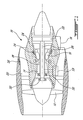
- FIG. 1 shows an example of a gas turbine engine with a power transfer system;
- FIG. 2 is an enlarged schematic view of an example of a power transfer system according to the invention;
- FIG. 3 is a schematic view of an example of a fuel heater;
- FIG.4 is a schematic top view of a multi-engine aircraft, showing an example of environment where power can be transferred from one engine to another; and
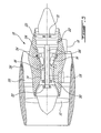
- FIG. 5 is view similar to FIG. 1, showing another aspect of the system.
- FIG. 1 illustrates an example of a
gas turbine engine 10 of a type preferably provided for use in subsonic flight, generally comprising in serial flow communication afan 12 through which ambient air is propelled, amultistage compressor 14 for pressurizing the air, acombustor 16 in which the compressed air is mixed with fuel and ignited for generating an annular stream of hot combustion gases, and aturbine section 18 for extracting energy from the combustion gases. - Gases flowing through the
turbine section 18 follow what is referred to hereafter as the core gas path. Some of the air drawn by thefan 12 is sent to a by-pass passage 20 provided around the core of theengine 10, thereby defining the by-pass gas path. It should be noted that the expression "gas path" used herein refers either to the core gas path or the by-pass gas path. - In a multi-spool engine, the
fan 12 is driven by a turbine, namely the low pressure (LP)turbine 22, via a shaft 26 (sometimes called the fan shaft). Some engines may have a single stage LP turbine, while others may have a multi-stage LP turbine. Thefan 12,LP turbine 22 andLP shaft 26 together form a unit within theengine 10 which unit is sometimes referred to as the LP spool, which may also optionally include an LP compressor in addition to thefan 12. - The
engine 10 also comprises a HP spool which includes the HPcompressor 14 driven by aturbine 24 from theturbine section 18. The HPturbine 24 and the HPcompressor 14 are connected together via a HPshaft 28. The HP spool and the LP spool are independently rotatable. - FIGS. 1 and 2 schematically show that the
engine 10 is preferably provided with an Integral Starter-Generator (ISG 30) driven by or driving (as the case may be) the HP shaft 28 via an appropriate connection. In the design of FIGS. 1 and 2, ISG 30 is preferably mounted to the HPshaft 28 using a direct, coaxial mechanical mounting. The ISG30 is preferably adapted to perform the functions of starting theengine 10 and generating electricity when theengine 10 is running. - In the design of FIGS. 1 and 2, as illustrated, the
ISG 30 is coaxially mounted with reference to the HPshaft 28. In another more conventional embodiment, shown in dotted lines in Figure 1, theISG 30 may be replaced by a starter-generator (not shown) mounted on the accessory gearbox (AGB 19). As the skilled reader will appreciate, the AGB 19 comprises a number of mechanically-driven components. The connection between the engine and the mechanically-driven components generally involves a tower shaft and corresponding gears. The mechanically driven components include an electric starter-generator which performs a function similar toISG 30 described herein. - FIGS. 1 and 2 further show an
electrical generator 32 mounted to theLP shaft 26 in order to transform torque therefrom into electrical power. The illustrated embodiment shows theelectrical generator 32 being coaxially mounted on theLP shaft 26. Other ways of connecting theelectrical generator 32 can be chosen, depending on the engine. Thiselectrical generator 32 is electrically connected to one or moreelectrical heaters Heaters electrical heaters 34 can be provided anywhere in the core gas path, either upstream or downstream of the compressor section. It is preferably adjacent to thecombustor 16. Heater(s) 34 may also be either upstream or downstream of thecombustor 16, or even on thecombustor 16. Heaters may also or alternately be located in or adjacent the gas path between turbine stages or downstream therefrom, or may be operatively associated with the fuel supply and adapted to heat the fuel using a resistiveelectrical fuel heater 35, as shown in FIG. 3. The skilled reader will appreciate, in light of this disclosure, that any means by which heat may be added to the gas turbine cycle may benefit from the teachings of the present invention. - One or more
electrical heaters 36 can be provided in the by-pass passage 20 at a suitable location, preferably towards the downstream end of the by-pass duct is preferred. - In use, when heater(s) 34 is activated in the core gas path in the region of the
combustor 16 of the engine, the heat added by the heater heats the air/gas flows passing therethrough and into the HPturbine 24, and thus has the effect as if added fuel has been burned in the combustor 16 (i.e. the combustion gases are hotter than they otherwise would have been without using more fuel at the combustor 16), and thus more thermal energy is provided to the gas flow for subsequent power extraction by the HPturbine 24. The added heat can also be used to reduce the amount of fuel supplied to thecombustor 16 to attain a specific gas temperature. Ifheater 34 is driven bygenerator 32 on the LP spool, the apparatus can be employed such that torque developed by theLP turbine 22 can be partially returned to the HPturbine 24. Since resistiveelectrical heaters turbines - When provided in the by-
pass passage 20, theheater 36 or set ofheaters 36 is operated to increase the temperature of the gases in the by-pass gas path and thereby increase thrust, in a manner analogous the manner in which an afterburner can increase the thrust of a gas turbine engine. - In these and other embodiments, the source of power for the
heaters electrical generator 32 and theISG 30, or only theISG 30, to provide electrical power to the heater(s) 36 in the by-pass passage 20. Other combinations and permutations are further possible, for instance with thefuel heater 35. - Operation of the transfer system is controlled using a
suitable controller 40, such as an electrical relay, electronic controller or another suitable arrangement, for controlling the electricity generation and flow between theelectrical generator 32, theISG 30 and the heater orheaters - Moreover, it is possible to transfer power between two or more engines of a same aircraft using the electrical heaters, whereby electrical power generated at one or more engines is used to power heaters in one or more other engines. For example, as shown in FIG. 4, in an
aircraft 100 having twoengines 10, forinstance turbofan engines engine aircraft power grid 105 to a suitable electrical heating arrangement (not shown) in theother engine APU 103, and vice-versa. - Also, the
electrical generator 32 of FIG. 2 can be used to draw power from the LP spool and thereby reduce the rotation speed of thefan 12. In an aircraft, this may allow the pilot to increase the core thrust without overspeeding thefan 12. It is also possible to simultaneously use electrical power from theISG 30 to heat the air in the by-pass gas path. - Other benefits of the present invention includes being able to restart an aircraft engine in flight using the windmilling effect on the
fan 12 caused by the continued movement of air through the moving butinoperative engine 10. The electrical power taken from the LP spool, which is windmilling, through the drivenelectrical generator 32 is sent to the appropriate heater to supply heat to the combustor to aid in re-lights. Theelectrical generator 32 can also be used to supply electrical power to other systems in case a generating failure of theISG 30. - Referring to FIG. 5, in another aspect another turbine such as
free turbine 23 may be provided preferably downstream of thelow turbine 22, theturbine 23 having agenerator 31 rotatably connected therewith, preferably mounted on its shaft (not indicated).Turbine 23 andgenerator 31 permits additional energy to be taken out of the gases before they leave the engine, that is, the rotation ofturbine 23 rotatesgenerator 31 for the generator of electrical power. That power can then be put into the gas turbine cycle, as desired, such as in ways which have already be described in this application. Thus additional energy may be reclaimed from the exhaust gases. - As can be appreciated, designing a gas turbine engine with a power transfer system as described herein provide many advantages, including being able to rematch available energy to another part of the engine when a spool is running faster than necessary during a segment of the engine cycle. This ultimately results in an increased of thrust or a decrease in fuel requirements during segments on the engine cycle. It provides an increased overall efficiency, including obtaining a better fuel consumption and particularly better handling performance during transients, if required.
- The above description is meant to be exemplary only, and one skilled in the art will recognize that changes may be made to the embodiments described without departing from the scope of the invention disclosed. For example, although a two-spool engine is generally referred to herein, the invention can be used on any multi-spool engine. The invention is applicable as well to turboprop gas turbine engines, in which case the propulsor is a propeller instead of the
fan 12 of theengine 10, and in turboshaft gas turbine engines, in which the reduction gearbox output (e.g. a helicopter rotor) is analogous to thefan 12 of theengine 10. The compressor and turbine can be of any kind, and either single stage or multi-stage. The invention is also not limited for use on aircraft prime-mover engines and can be implemented on various gas turbine engines used in other contexts, such as aircraft APUs and ground-based gas turbine engines. Although resistance heaters located physically outside the gas path are preferred due to their efficiency and non-interference with the gas path in such a configuration, other heating types and configurations may be provided. For example, the heater may be in, or extend into the gas path. Still other modifications of the present invention will be apparent to those skilled in the art, in light of a review of this disclosure.
Claims (22)
- A gas turbine engine (10) comprising:at least one electrical generator (30, 32) rotationally connected to an engine shaft;an electrical heater (34, 35, 36) associated with a gas path of the engine and adapted to heat gases in the gas path, the heater being electrically connected to the generator; anda controller (40) adapted to selectively control the heater (34, 35, 36) to add heat to the gas path.
- The gas turbine engine as defined in claim 1, wherein the gas path is a core gas path of the engine, the core gas path passing successively though at least one compressor (14), combustor (16) and turbine stage (18) of the engine (10).
- The gas turbine engine as defined in claim 2, wherein the heater (34) is located at one or more locations selected from the group consisting of: upstream the combustor stage (16), downstream the combustor stage (16), and in the combustor stage (16).
- The gas turbine engine as defined in claim 2 or 3, wherein the turbine stage (18) comprises multiple turbines, and the heater (34) is located between two of said turbines.
- The gas turbine engine as defined in claim 2, wherein the heater (35) is located in the fuel supply system, and adapted to heat the fuel to thereby add heat to the gas path.
- The gas turbine engine as defined in claim 1, wherein the gas path is a by-pass passage of the engine.
- A gas turbine engine (10) comprising:at least a first (26) and a second shaft (28), the first shaft (26) rotatably supporting at least a propulsor (12) and a low pressure turbine (22), the second shaft (28) rotatably supporting at least a compressor (14) and a high pressure turbine (24);an electrical generator (32) mounted to the first shaft (26); andan electrical heater (34, 35) electrically connected to the generator (32), the heater (34, 35) being provided to selectively add heat to gases in a gas path passing through the high pressure turbine (24).
- The gas turbine engine as defined in claim 7, further comprising a second electrical heater (36) connected to the generator (32), the second heater (36) being disposed in a by-pass passage (20) of the engine (10) to selectively add heat to air therein using at least some electrical power from the generator (32).
- The gas turbine engine as defined in claim 7, further comprising a second electrical generator (30) mounted to the second shaft (28), and a second electrical heater (36) connected to the first (32) and the second (30) generator, the second heater (36) being disposed in a by-pass passage (20) of the engine (10) to selectively add heat to air therein using electrical power from the first generator (32), the second generator (30), or both.
- A gas turbine engine (10) comprising:means (30, 32) for transforming torque from an engine shaft (26, 28) into electrical power;means (34, 35, 36) for heating gases in a gas path within the engine (10) using the electrical power from the first means so as to increase thrust caused by the gases in the gas path; andmeans (40) for controlling the electrical power transferred from the first means to the second means.
- The gas turbine engine as defined in claim 10, wherein the gas path includes a core gas path.
- The gas turbine engine as defined in claim 10 or 11, wherein the gas path includes a by-pass gas path.
- A method of generating thrust by transferring power between a first and a second location in a gas turbine engine (10), the method comprising:transforming torque generated by the engine (10) into electrical power; andusing the electrical power to heat gases in a gas path.
- The method as defined in claim 13, wherein the gas path includes a core gas path, and wherein the heat is converted to thrust by a turbine.
- The method as defined in claim 13, wherein the gas path includes a by-pass gas path, and wherein the heat is converted to thrust in a by-pass duct (20).
- A method of generating thrust by transferring power between two gas turbine engines (101, 102), the method comprising:transforming torque generated in the first gas turbine engine (101) into electrical power; andadding heat to gases in a gas path of the second gas turbine engine (102) using the electrical power from the first gas turbine engine (101), at least a portion of the added heat in the second gas turbine engine (102) being converted into mechanical power.
- The method as defined in claim 16, wherein the gas path is a core gas path of the second gas turbine engine (102), the core gas path passing successively though at least one compressor (14), combustor (16) and turbine stage (18) thereof.
- The method as defined in claim 17, wherein the heat is added at one or more locations of the second gas turbine engine (102) selected from the group consisting of: upstream the combustor stage (16), downstream the combustor stage (16), and in the combustor stage (16).
- The method as defined in claim 17 or 18, wherein the turbine stage (18) comprises multiple turbines, and the heat being added between two of said turbines.
- The method as defined in claim 17 or 18, wherein at least some of the heat is added to the second gas turbine engine (102) by heating fuel to be burned in the second gas turbine engine (102).
- The method as defined in claim 16, wherein the gas path is a by-pass passage (20) of the second gas turbine engine (102).
- An aircraft gas turbine engine (10), the engine including comprising at least a compression stage (14), a combustion stage (16) and a turbine stage (18), the compression stage (14) and turbine stage (18) rotatably connected by at least one rotatable shaft (26, 28), the engine further comprising a free turbine (23) connected to rotate with an electrical generator (31), the free turbine (23) mechanically unconnected with any compression stage (14) of the engine (10), the engine (10) further comprising a heat input apparatus adapted to convert electricity generated by the electrical generator (31) in response to free turbine rotation into heat, wherein the heat input apparatus is adapted to add said heat to a gas turbine cycle of the gas turbine engine (10).
Applications Claiming Priority (1)
| Application Number | Priority Date | Filing Date | Title |
|---|---|---|---|
| US11/269,699 US7690186B2 (en) | 2005-11-09 | 2005-11-09 | Gas turbine engine including apparatus to transfer power between multiple shafts |
Publications (2)
| Publication Number | Publication Date |
|---|---|
| EP1785617A1 true EP1785617A1 (en) | 2007-05-16 |
| EP1785617B1 EP1785617B1 (en) | 2008-10-15 |
Family
ID=37636772
Family Applications (1)
| Application Number | Title | Priority Date | Filing Date |
|---|---|---|---|
| EP06255643A Active EP1785617B1 (en) | 2005-11-09 | 2006-11-02 | Gas turbine engine with power transfer and method |
Country Status (6)
| Country | Link |
|---|---|
| US (2) | US7690186B2 (en) |
| EP (1) | EP1785617B1 (en) |
| JP (1) | JP2009515081A (en) |
| CA (1) | CA2625851C (en) |
| DE (1) | DE602006003172D1 (en) |
| WO (1) | WO2007053931A1 (en) |
Cited By (5)
| Publication number | Priority date | Publication date | Assignee | Title |
|---|---|---|---|---|
| GB2444784A (en) * | 2006-12-13 | 2008-06-18 | David Duckett | Electrical resistance heating of compressed air supply in gas turbine engine |
| FR2943093A1 (en) * | 2009-03-16 | 2010-09-17 | Snecma | Stator for e.g. radial compressor of airplane jet engine, has connection arm with heating unit that is controlled to adjust radial and/or axial positions of shroud and has resistors arranged symmetrically with respect to median plane of arm |
| WO2011127901A1 (en) * | 2010-04-14 | 2011-10-20 | Mtu Aero Engines Gmbh | Multi-shaft engine having a tandem generator |
| WO2011121355A3 (en) * | 2010-03-31 | 2012-01-12 | Bladon Jets Holdings Limited | Gas turbines |
| EP2949876A1 (en) * | 2014-05-29 | 2015-12-02 | Rolls-Royce Corporation | System and method to manage engine transients for rapid power demand changes |
Families Citing this family (46)
| Publication number | Priority date | Publication date | Assignee | Title |
|---|---|---|---|---|
| US20060156733A1 (en) * | 2005-01-14 | 2006-07-20 | Pratt & Whitney Canada Corp. | Integral heater for fuel conveying member |
| US7690186B2 (en) * | 2005-11-09 | 2010-04-06 | Pratt & Whitney Canada Corp. | Gas turbine engine including apparatus to transfer power between multiple shafts |
| US7854582B2 (en) | 2007-05-08 | 2010-12-21 | Pratt & Whitney Canada Corp. | Operation of an aircraft engine after emergency shutdown |
| US7926287B2 (en) | 2007-05-08 | 2011-04-19 | Pratt & Whitney Canada Corp. | Method of operating a gas turbine engine |
| US8061119B2 (en) * | 2007-11-29 | 2011-11-22 | United Technologies Corporation | Actuation mechanism for a convertible gas turbine propulsion system |
| US8511058B2 (en) * | 2007-11-29 | 2013-08-20 | United Technologies Corporation | Convertible gas turbine propulsion system |
| KR100941239B1 (en) * | 2008-03-14 | 2010-02-10 | 현대자동차주식회사 | Torque control method of hybrid vehicle |
| US20100162720A1 (en) * | 2008-12-31 | 2010-07-01 | Bowman Ray F | Gas turbine engine |
| US8097972B2 (en) * | 2009-06-29 | 2012-01-17 | Pratt & Whitney Canada Corp. | Gas turbine with magnetic shaft forming part of a generator/motor assembly |
| US8278774B2 (en) | 2009-06-29 | 2012-10-02 | Pratt & Whitney Canada Corp. | Gas turbine with wired shaft forming part of a generator/motor assembly |
| FR2957585B1 (en) * | 2010-03-17 | 2012-03-02 | Airbus Operations Sas | METHOD AND DEVICE FOR DRIVING AT LEAST ONE WHEEL OF LANDING TRAIN OF AN AIRCRAFT BY A WHEELED ENGINE |
| US8424416B2 (en) | 2010-06-18 | 2013-04-23 | Hamilton Sundstrand Corporation | Layshaft generator |
| US8519555B2 (en) * | 2010-11-29 | 2013-08-27 | Pratt & Whitney Canada Corp. | Combination low spool generator and ram air turbine generator |
| US9051881B2 (en) * | 2010-12-28 | 2015-06-09 | Rolls-Royce Corporation | Electrical power generation and windmill starting for turbine engine and aircraft |
| US8928166B2 (en) * | 2011-08-31 | 2015-01-06 | Hamilton Sundstrand Corporation | Mixed mode power generation architecture |
| US9267438B2 (en) | 2011-10-11 | 2016-02-23 | Pratt & Whitney Canada Corp. | Starting of aircraft engine |
| US9429077B2 (en) | 2011-12-06 | 2016-08-30 | Pratt & Whitney Canada Corp. | Multiple turboshaft engine control method and system for helicopters |
| EP2629407B1 (en) | 2012-02-17 | 2014-12-24 | Bell Helicopter Textron Inc. | Electrical generator for rotating structure |
| ITFI20120161A1 (en) * | 2012-08-03 | 2014-02-04 | Nuovo Pignone Srl | "DUAL-END DRIVE GAS TURBINE" |
| US9045996B2 (en) * | 2012-11-20 | 2015-06-02 | Honeywell International Inc. | Gas turbine engine optimization by electric power transfer |
| US9260976B2 (en) | 2013-03-13 | 2016-02-16 | Rolls-Royce North American Technologies, Inc. | Engine health monitoring and power allocation control for a turbine engine using electric generators |
| US9853581B2 (en) | 2013-03-15 | 2017-12-26 | Rolls-Royce Corporation | Lifing and performance optimization limit management for turbine engine |
| US20160076450A1 (en) * | 2014-04-21 | 2016-03-17 | Bob Burkett | Solar Jet Turbofan Aircraft Engine |
| JP6324521B2 (en) * | 2014-09-22 | 2018-05-16 | 三菱電機株式会社 | Rotating electric machine stator |
| US10030558B2 (en) | 2015-06-29 | 2018-07-24 | General Electric Company | Power generation system exhaust cooling |
| US20160376909A1 (en) * | 2015-06-29 | 2016-12-29 | General Electric Company | Power generation system exhaust cooling |
| US9856768B2 (en) | 2015-06-29 | 2018-01-02 | General Electric Company | Power generation system exhaust cooling |
| US9850794B2 (en) | 2015-06-29 | 2017-12-26 | General Electric Company | Power generation system exhaust cooling |
| US10087801B2 (en) | 2015-06-29 | 2018-10-02 | General Electric Company | Power generation system exhaust cooling |
| US10077694B2 (en) | 2015-06-29 | 2018-09-18 | General Electric Company | Power generation system exhaust cooling |
| US9840953B2 (en) | 2015-06-29 | 2017-12-12 | General Electric Company | Power generation system exhaust cooling |
| US10060316B2 (en) | 2015-06-29 | 2018-08-28 | General Electric Company | Power generation system exhaust cooling |
| US9938874B2 (en) | 2015-06-29 | 2018-04-10 | General Electric Company | Power generation system exhaust cooling |
| US9850818B2 (en) | 2015-06-29 | 2017-12-26 | General Electric Company | Power generation system exhaust cooling |
| US10215070B2 (en) | 2015-06-29 | 2019-02-26 | General Electric Company | Power generation system exhaust cooling |
| US10316759B2 (en) | 2016-05-31 | 2019-06-11 | General Electric Company | Power generation system exhaust cooling |
| FR3070184B1 (en) * | 2017-08-21 | 2019-08-23 | Safran Aircraft Engines | HOT AIR DELIVERY SYSTEM AT THE COLLAR OF A CONVERGENT-DIVERGENT SECONDARY PIPE |
| FR3087822B1 (en) * | 2018-10-26 | 2020-11-06 | Safran Aircraft Engines | TURBOMACHINE WITH ELECTRIC MACHINE INCLUDING A ROTOR RING HELD TO THE BLOWER |
| US11286805B2 (en) * | 2020-06-22 | 2022-03-29 | Florida Turbine Technologies, Inc. | Multi-spool geared turbofan arrangement with integrated starter/generator |
| US11713733B2 (en) * | 2021-08-13 | 2023-08-01 | Pratt & Whitney Canada Corp. | Methods and systems for operating an engine to generate additional thrust |
| US11629596B1 (en) * | 2021-10-08 | 2023-04-18 | Pratt & Whitney Canada Corp. | Rotor assembly for a gas turbine engine and method for assembling same |
| US11867137B1 (en) * | 2021-10-25 | 2024-01-09 | Jesse LaSalle McQueen | Jet engine having electrically powered superheating section |
| FR3132279B1 (en) * | 2022-02-01 | 2024-01-12 | Safran Aircraft Engines | Braking process for an aircraft turbomachine |
| CN114753925A (en) * | 2022-05-12 | 2022-07-15 | 沈阳漠南动力科技有限公司 | Electric energy turbine engine |
| US12392290B2 (en) | 2022-11-01 | 2025-08-19 | General Electric Company | Gas turbine engine |
| JP2024100234A (en) * | 2023-01-13 | 2024-07-26 | 大電爾晃一製作所合同会社 | Power plant system |
Citations (3)
| Publication number | Priority date | Publication date | Assignee | Title |
|---|---|---|---|---|
| US5694765A (en) | 1993-07-06 | 1997-12-09 | Rolls-Royce Plc | Shaft power transfer in gas turbine engines with machines operable as generators or motors |
| WO1999032763A1 (en) * | 1997-12-20 | 1999-07-01 | Alliedsignal Inc. | A LOW NOx CONDITIONER SYSTEM AND PROCESS FOR A MICROTURBINE POWER GENERATING SYSTEM |
| US20020083714A1 (en) * | 2000-11-01 | 2002-07-04 | Daniel Bakholdin | Liquid fuel combustion system and method |
Family Cites Families (35)
| Publication number | Priority date | Publication date | Assignee | Title |
|---|---|---|---|---|
| US3060679A (en) * | 1958-10-24 | 1962-10-30 | Gen Electric | Powerplant |
| US3237403A (en) * | 1963-03-19 | 1966-03-01 | Douglas Aircraft Co Inc | Supercritical cycle heat engine |
| DE2103035C3 (en) * | 1970-02-05 | 1975-03-27 | Secretary Of State For Defence Of The United Kingdom Of Great Britain And Northern Ireland, London | Air inlet for gas turbine engines |
| US3705491A (en) * | 1970-06-30 | 1972-12-12 | Richard W Foster Pegg | Jet engine air compressor |
| US3796854A (en) * | 1972-09-25 | 1974-03-12 | Westinghouse Electric Corp | Ice detection system for a gas turbine |
| US3797233A (en) * | 1973-06-28 | 1974-03-19 | United Aircraft Corp | Integrated control for a turbopropulsion system |
| US4137708A (en) * | 1973-07-02 | 1979-02-06 | General Motors Corporation | Jet propulsion |
| US3922849A (en) * | 1973-10-09 | 1975-12-02 | Aerojet General Co | Injector for gas turbine combustor |
| US3999378A (en) * | 1974-01-02 | 1976-12-28 | General Electric Company | Bypass augmentation burner arrangement for a gas turbine engine |
| US4089638A (en) * | 1976-07-29 | 1978-05-16 | Trucco Horacio A | Apparatus for gassification, premixing and combustion of liquid fuels |
| US4262482A (en) * | 1977-11-17 | 1981-04-21 | Roffe Gerald A | Apparatus for the premixed gas phase combustion of liquid fuels |
| US4782658A (en) * | 1987-05-07 | 1988-11-08 | Rolls-Royce Plc | Deicing of a geared gas turbine engine |
| GB2243412B (en) * | 1990-03-30 | 1994-11-23 | United Technologies Corp | Aircraft engine propulsor blade deicing |
| US5174717A (en) * | 1991-06-10 | 1992-12-29 | Safeway Products Inc. | Cable harness and mounting hardware for propeller deicer |
| JP2950720B2 (en) * | 1994-02-24 | 1999-09-20 | 株式会社東芝 | Gas turbine combustion device and combustion control method therefor |
| US5683062A (en) * | 1995-02-27 | 1997-11-04 | General Electric Company | Aircraft anti-insect system |
| US5845483A (en) * | 1996-04-10 | 1998-12-08 | General Electric Company | Windmill engine starting system with fluid driven motor and pump |
| US6107693A (en) * | 1997-09-19 | 2000-08-22 | Solo Energy Corporation | Self-contained energy center for producing mechanical, electrical, and heat energy |
| US20020099476A1 (en) * | 1998-04-02 | 2002-07-25 | Hamrin Douglas A. | Method and apparatus for indirect catalytic combustor preheating |
| US20020166324A1 (en) * | 1998-04-02 | 2002-11-14 | Capstone Turbine Corporation | Integrated turbine power generation system having low pressure supplemental catalytic reactor |
| US6167692B1 (en) * | 1998-06-29 | 2001-01-02 | General Electric Co. | Method of using fuel gas expander in power generating plants |
| GB9910393D0 (en) * | 1999-05-05 | 1999-07-07 | Lucas Ind Plc | Electrical generator,an aero-engine including such a generator and an aircraft including such a generator |
| US6862330B2 (en) * | 2000-12-12 | 2005-03-01 | General Electric Company | Systems and methods of producing hydrogen using a nuclear reactor |
| US6606864B2 (en) * | 2001-02-13 | 2003-08-19 | Robin Mackay | Advanced multi pressure mode gas turbine |
| FR2826052B1 (en) * | 2001-06-19 | 2003-12-19 | Snecma Moteurs | RELIEF DEVICE FOR THE IGNITION OF A SELF-ROTATING TURBO-JET |
| US6735954B2 (en) * | 2001-12-21 | 2004-05-18 | Pratt & Whitney Canada Corp. | Offset drive for gas turbine engine |
| US6725645B1 (en) * | 2002-10-03 | 2004-04-27 | General Electric Company | Turbofan engine internal anti-ice device |
| GB2397347A (en) | 2003-01-20 | 2004-07-21 | Rolls Royce Plc | Deriving electrical energy from waste heat in a gas turbine engine |
| US6873071B2 (en) * | 2003-06-03 | 2005-03-29 | Pratt & Whitney Canada Corp. | Method, apparatus and system for controlling an electric machine |
| US7131815B2 (en) * | 2003-07-11 | 2006-11-07 | Rolls-Royce Plc | Inlet guide vane |
| US6951105B1 (en) * | 2004-04-20 | 2005-10-04 | Smith Edward J | Electro-water reactor steam powered electric generator system |
| US20070089423A1 (en) * | 2005-10-24 | 2007-04-26 | Norman Bruce G | Gas turbine engine system and method of operating the same |
| US7690186B2 (en) * | 2005-11-09 | 2010-04-06 | Pratt & Whitney Canada Corp. | Gas turbine engine including apparatus to transfer power between multiple shafts |
| US8210825B2 (en) * | 2007-05-11 | 2012-07-03 | Honeywell International Inc. | Heated engine nose cone using spiral channels |
| US8844293B2 (en) * | 2011-03-22 | 2014-09-30 | Pratt & Whitney Canada Corp. | Fuel system for gas turbine engine |
-
2005
- 2005-11-09 US US11/269,699 patent/US7690186B2/en active Active
-
2006
- 2006-08-04 JP JP2008539198A patent/JP2009515081A/en active Pending
- 2006-08-04 CA CA2625851A patent/CA2625851C/en not_active Expired - Lifetime
- 2006-08-04 WO PCT/CA2006/001273 patent/WO2007053931A1/en not_active Ceased
- 2006-11-02 EP EP06255643A patent/EP1785617B1/en active Active
- 2006-11-02 DE DE602006003172T patent/DE602006003172D1/en active Active
-
2010
- 2010-02-19 US US12/708,789 patent/US8631655B2/en active Active
Patent Citations (3)
| Publication number | Priority date | Publication date | Assignee | Title |
|---|---|---|---|---|
| US5694765A (en) | 1993-07-06 | 1997-12-09 | Rolls-Royce Plc | Shaft power transfer in gas turbine engines with machines operable as generators or motors |
| WO1999032763A1 (en) * | 1997-12-20 | 1999-07-01 | Alliedsignal Inc. | A LOW NOx CONDITIONER SYSTEM AND PROCESS FOR A MICROTURBINE POWER GENERATING SYSTEM |
| US20020083714A1 (en) * | 2000-11-01 | 2002-07-04 | Daniel Bakholdin | Liquid fuel combustion system and method |
Cited By (8)
| Publication number | Priority date | Publication date | Assignee | Title |
|---|---|---|---|---|
| GB2444784A (en) * | 2006-12-13 | 2008-06-18 | David Duckett | Electrical resistance heating of compressed air supply in gas turbine engine |
| FR2943093A1 (en) * | 2009-03-16 | 2010-09-17 | Snecma | Stator for e.g. radial compressor of airplane jet engine, has connection arm with heating unit that is controlled to adjust radial and/or axial positions of shroud and has resistors arranged symmetrically with respect to median plane of arm |
| WO2011121355A3 (en) * | 2010-03-31 | 2012-01-12 | Bladon Jets Holdings Limited | Gas turbines |
| GB2491791A (en) * | 2010-03-31 | 2012-12-12 | Bladon Jets Holdings Ltd | Gas turbines |
| GB2491791B (en) * | 2010-03-31 | 2015-11-18 | Bladon Jets Holdings Ltd | Gas turbines |
| WO2011127901A1 (en) * | 2010-04-14 | 2011-10-20 | Mtu Aero Engines Gmbh | Multi-shaft engine having a tandem generator |
| EP2949876A1 (en) * | 2014-05-29 | 2015-12-02 | Rolls-Royce Corporation | System and method to manage engine transients for rapid power demand changes |
| US9765640B2 (en) | 2014-05-29 | 2017-09-19 | Rolls-Royce Corporation | System and method to manage transients for rapid power demand changes |
Also Published As
| Publication number | Publication date |
|---|---|
| US20110036093A1 (en) | 2011-02-17 |
| WO2007053931A1 (en) | 2007-05-18 |
| DE602006003172D1 (en) | 2008-11-27 |
| EP1785617B1 (en) | 2008-10-15 |
| CA2625851A1 (en) | 2007-05-18 |
| US20070101696A1 (en) | 2007-05-10 |
| US7690186B2 (en) | 2010-04-06 |
| CA2625851C (en) | 2013-10-29 |
| US8631655B2 (en) | 2014-01-21 |
| JP2009515081A (en) | 2009-04-09 |
Similar Documents
| Publication | Publication Date | Title |
|---|---|---|
| US8631655B2 (en) | Gas turbine engine including apparatus to transfer power between multiple shafts | |
| US11815024B2 (en) | Thermal management system | |
| CN114837807B (en) | Aircraft propulsion system with inter-turbine combustor | |
| US11506131B2 (en) | Thermal management system | |
| US11671040B2 (en) | Turbomachine with an electric machine assembly and method for operation | |
| US20210262398A1 (en) | Gas turbine engine stall margin management | |
| US11391211B2 (en) | Waste heat recovery system | |
| US11143104B2 (en) | Thermal management system | |
| CA2961056C (en) | Engine bleed system with turbo-compressor | |
| US9328667B2 (en) | Systems and methods for changing a speed of a compressor boost stage in a gas turbine | |
| EP3957843B1 (en) | Hybrid through-flow gas turbine engine with electric motor and electric generator | |
| EP3219620B1 (en) | Engine bleed system with motorized compressor | |
| EP3910174A1 (en) | Reverse-flow gas turbine engine with electric motor | |
| EP4227515B1 (en) | Turbine engine with inverse brayton cycle | |
| US12054268B2 (en) | Hybrid propulsion system including electric motor with fan shroud encircling integrated fan blades | |
| CN116906186A (en) | Transient control of a heat transfer bus | |
| CN115853666A (en) | Turbine engine with variable pitch fan |
Legal Events
| Date | Code | Title | Description |
|---|---|---|---|
| PUAI | Public reference made under article 153(3) epc to a published international application that has entered the european phase |
Free format text: ORIGINAL CODE: 0009012 |
|
| AK | Designated contracting states |
Kind code of ref document: A1 Designated state(s): AT BE BG CH CY CZ DE DK EE ES FI FR GB GR HU IE IS IT LI LT LU LV MC NL PL PT RO SE SI SK TR |
|
| AX | Request for extension of the european patent |
Extension state: AL BA HR MK YU |
|
| 17P | Request for examination filed |
Effective date: 20070518 |
|
| 17Q | First examination report despatched |
Effective date: 20070627 |
|
| AKX | Designation fees paid |
Designated state(s): DE FR GB |
|
| GRAP | Despatch of communication of intention to grant a patent |
Free format text: ORIGINAL CODE: EPIDOSNIGR1 |
|
| GRAS | Grant fee paid |
Free format text: ORIGINAL CODE: EPIDOSNIGR3 |
|
| GRAA | (expected) grant |
Free format text: ORIGINAL CODE: 0009210 |
|
| AK | Designated contracting states |
Kind code of ref document: B1 Designated state(s): DE FR GB |
|
| REG | Reference to a national code |
Ref country code: GB Ref legal event code: FG4D |
|
| REF | Corresponds to: |
Ref document number: 602006003172 Country of ref document: DE Date of ref document: 20081127 Kind code of ref document: P |
|
| PLBE | No opposition filed within time limit |
Free format text: ORIGINAL CODE: 0009261 |
|
| STAA | Information on the status of an ep patent application or granted ep patent |
Free format text: STATUS: NO OPPOSITION FILED WITHIN TIME LIMIT |
|
| 26N | No opposition filed |
Effective date: 20090716 |
|
| REG | Reference to a national code |
Ref country code: FR Ref legal event code: PLFP Year of fee payment: 10 |
|
| REG | Reference to a national code |
Ref country code: FR Ref legal event code: PLFP Year of fee payment: 11 |
|
| REG | Reference to a national code |
Ref country code: DE Ref legal event code: R082 Ref document number: 602006003172 Country of ref document: DE Representative=s name: SCHMITT-NILSON SCHRAUD WAIBEL WOHLFROM PATENTA, DE |
|
| REG | Reference to a national code |
Ref country code: FR Ref legal event code: PLFP Year of fee payment: 12 |
|
| REG | Reference to a national code |
Ref country code: FR Ref legal event code: PLFP Year of fee payment: 13 |
|
| PGFP | Annual fee paid to national office [announced via postgrant information from national office to epo] |
Ref country code: DE Payment date: 20181023 Year of fee payment: 13 |
|
| REG | Reference to a national code |
Ref country code: DE Ref legal event code: R119 Ref document number: 602006003172 Country of ref document: DE |
|
| PG25 | Lapsed in a contracting state [announced via postgrant information from national office to epo] |
Ref country code: DE Free format text: LAPSE BECAUSE OF NON-PAYMENT OF DUE FEES Effective date: 20200603 |
|
| P01 | Opt-out of the competence of the unified patent court (upc) registered |
Effective date: 20230530 |
|
| PGFP | Annual fee paid to national office [announced via postgrant information from national office to epo] |
Ref country code: GB Payment date: 20251023 Year of fee payment: 20 |
|
| PGFP | Annual fee paid to national office [announced via postgrant information from national office to epo] |
Ref country code: FR Payment date: 20251022 Year of fee payment: 20 |