EP1785463A1 - Granules, and method of forming fluorescent surface ofplasma display panel using them - Google Patents
Granules, and method of forming fluorescent surface ofplasma display panel using them Download PDFInfo
- Publication number
- EP1785463A1 EP1785463A1 EP05765408A EP05765408A EP1785463A1 EP 1785463 A1 EP1785463 A1 EP 1785463A1 EP 05765408 A EP05765408 A EP 05765408A EP 05765408 A EP05765408 A EP 05765408A EP 1785463 A1 EP1785463 A1 EP 1785463A1
- Authority
- EP
- European Patent Office
- Prior art keywords
- granule
- granules
- fluorescent
- cells
- mask sheet
- Prior art date
- Legal status (The legal status is an assumption and is not a legal conclusion. Google has not performed a legal analysis and makes no representation as to the accuracy of the status listed.)
- Withdrawn
Links
Images


Classifications
-
- C—CHEMISTRY; METALLURGY
- C09—DYES; PAINTS; POLISHES; NATURAL RESINS; ADHESIVES; COMPOSITIONS NOT OTHERWISE PROVIDED FOR; APPLICATIONS OF MATERIALS NOT OTHERWISE PROVIDED FOR
- C09K—MATERIALS FOR MISCELLANEOUS APPLICATIONS, NOT PROVIDED FOR ELSEWHERE
- C09K11/00—Luminescent materials, e.g. electroluminescent or chemiluminescent
- C09K11/02—Use of particular materials as binders, particle coatings or suspension media therefor
-
- C—CHEMISTRY; METALLURGY
- C09—DYES; PAINTS; POLISHES; NATURAL RESINS; ADHESIVES; COMPOSITIONS NOT OTHERWISE PROVIDED FOR; APPLICATIONS OF MATERIALS NOT OTHERWISE PROVIDED FOR
- C09K—MATERIALS FOR MISCELLANEOUS APPLICATIONS, NOT PROVIDED FOR ELSEWHERE
- C09K11/00—Luminescent materials, e.g. electroluminescent or chemiluminescent
- C09K11/08—Luminescent materials, e.g. electroluminescent or chemiluminescent containing inorganic luminescent materials
- C09K11/77—Luminescent materials, e.g. electroluminescent or chemiluminescent containing inorganic luminescent materials containing rare earth metals
- C09K11/7728—Luminescent materials, e.g. electroluminescent or chemiluminescent containing inorganic luminescent materials containing rare earth metals containing europium
- C09K11/7734—Aluminates
-
- C—CHEMISTRY; METALLURGY
- C09—DYES; PAINTS; POLISHES; NATURAL RESINS; ADHESIVES; COMPOSITIONS NOT OTHERWISE PROVIDED FOR; APPLICATIONS OF MATERIALS NOT OTHERWISE PROVIDED FOR
- C09K—MATERIALS FOR MISCELLANEOUS APPLICATIONS, NOT PROVIDED FOR ELSEWHERE
- C09K11/00—Luminescent materials, e.g. electroluminescent or chemiluminescent
- C09K11/08—Luminescent materials, e.g. electroluminescent or chemiluminescent containing inorganic luminescent materials
- C09K11/59—Luminescent materials, e.g. electroluminescent or chemiluminescent containing inorganic luminescent materials containing silicon
- C09K11/592—Chalcogenides
- C09K11/595—Chalcogenides with zinc or cadmium
-
- C—CHEMISTRY; METALLURGY
- C09—DYES; PAINTS; POLISHES; NATURAL RESINS; ADHESIVES; COMPOSITIONS NOT OTHERWISE PROVIDED FOR; APPLICATIONS OF MATERIALS NOT OTHERWISE PROVIDED FOR
- C09K—MATERIALS FOR MISCELLANEOUS APPLICATIONS, NOT PROVIDED FOR ELSEWHERE
- C09K11/00—Luminescent materials, e.g. electroluminescent or chemiluminescent
- C09K11/08—Luminescent materials, e.g. electroluminescent or chemiluminescent containing inorganic luminescent materials
- C09K11/77—Luminescent materials, e.g. electroluminescent or chemiluminescent containing inorganic luminescent materials containing rare earth metals
- C09K11/7783—Luminescent materials, e.g. electroluminescent or chemiluminescent containing inorganic luminescent materials containing rare earth metals containing two or more rare earth metals one of which being europium
- C09K11/7797—Borates
-
- H—ELECTRICITY
- H01—ELECTRIC ELEMENTS
- H01J—ELECTRIC DISCHARGE TUBES OR DISCHARGE LAMPS
- H01J2211/00—Plasma display panels with alternate current induction of the discharge, e.g. AC-PDPs
- H01J2211/20—Constructional details
- H01J2211/34—Vessels, containers or parts thereof, e.g. substrates
- H01J2211/42—Fluorescent layers
Definitions
- the present invention relates to a granule used in forming a fluorescent surface of plasma display panel and a method for forming the fluorescent surface of plasma display panel.
- Figure 1 is a cross-sectional view for illustrating a structure of plasma display panel.
- a plasma display panel 10 is constituted by a first substrate 11 and a second substrate 12 which are disposed in parallel and opposite to each other. On any one of surfaces on these substrates 11 and 12 (second substrate 12 in Figure 1), a barrier 13 is provided.
- a cell 14 (sub pixel) is formed as a display element.
- a fluorescent surface 15 (15R, 15G, 15B) made from a fluorescent substance for generating fluorescence of, for example, red (R), green (G), and blue (B) is provided inside the cell 14.
- Electrodes 16 and 17 are provided in the first substrate 11 and the second substrate 12 for discharging electricity inside the cell 14.
- a technique utilized now, as a method of forming such a fluorescent surface 15 for plasma display panels 10, is to print fluorescent paints of red color (R), green color (G), and blue color (B)in paste form by a screen printing and so on, and thereafter dry and bake the fluorescent paints.
- the fluorescent surface 15 is formed by a screen printing or the like, it is difficult to simultaneously print three colors of red (R), green (G), and blue (B). Therefore, it is necessary to form a fluorescent surface 15R of red color (R) by printing and drying a red fluorescent paint, then form a fluorescent surface 15G of green color (G) by printing and drying a green fluorescent paint, and then form a fluorescent surface 15B of blue color (B) by printing and drying a blue fluorescent paint. Substantial time and labor are required in separately providing each of the colors like that manner.
- An illustrative object of the present invention is to provide a novel method for forming a fluorescent surface of plasma display panel, the method being different from a conventional method, and a novel granule used for this method.
- the invention recited in Claim 1 is about a granule having characteristics that an organic binder is used as an auxiliary forming component and a fluorescent substance is dispersed and blended.
- the invention recited in Claim 4 is related to a method of forming a fluorescent surface of a plasma display panel having a plurality of cells as display elements provided in it, the cells being formed by barriers provided on any one of first and second substrates, which are disposed in parallel and opposite to each other, and the cells also being provided with the fluorescent surfaces made from a fluorescent substance in the plurality of cells, the method including steps of:
- a granule according to the present invention is specifically described in reference of the figures.
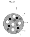
- Figure 2 is a cross-sectional view schematically showing a granule 20 according to the present invention.
- the granule 20 is characterized by having a fluorescent substance 22 dispersed and blended into it with use of an organic binder 21 as an auxiliary forming component.
- Such the granule 20 is preferably used in "a method for forming a fluorescent surface of plasma display panel" described below according to the present invention. Although detail of “a method for forming a fluorescent surface of plasma display panel” according to the present invention will be described later, it is possible to easily provide a fluorescent surface for plasma display panel inside a predetermined cell with use of the granule according to the present invention. Because the granule 20 is a solid state under an ordinary temperature, it can be easily treated.
- An organic binder 21 constituting the granule 20 according to the present invention may be any binder as long as a fluorescent substance can be dispersed and blended into it, and further the organic binder can be formed in a granule-like shape. Further, in "a method for forming a fluorescent surface of plasma display panel" according to the present invention, it is necessary to melt the granule during processes of the method. Therefore, it is necessary to melt the granule so as to be in a liquid state by heating it at an adequate temperature (ordinary temperature or more, e.g. 50-180 °C (Celsius)).
- Such the organic binder 21 is specifically acrylic resin, polyester resin, various waxes (e.g. paraffinic wax), and so on.
- the fluorescent substance 22 to be dispersed and blended into the above organic binder itself conclusively becomes a fluorescent surface in a case where the fluorescent surface (15) of plasma display panel (10) is formed in use of for example the granule 20 (vide Figure 1).
- the fluorescent substance 22 is not specifically limited in the present invention, and it is possible to use all fluorescent substances (specifically fluorescent substances of red color, green color, and blue color), used for forming the fluorescent surfaces for plasma display by now.
- the fluorescent substance 22 blended into one granule 20 has only any one of the colors (any one color of RGB).
- (Y x Gd 1-x )BO 3 :Eu 3+ may be used as the red fluorescent substance; Zn 2 SiO 4 :Mn 2+ may be used as the green fluorescent substance; and BaMgAl 10 O 17 :Eu 2+ may be used as the blue fluorescent substance.
- any one or both of an electric charge material 23 and a magnetic material 24 maybe dispersed and blended into the granule 20 according to the present invention in addition to the above fluorescent substance 22.
- a method for forming a fluorescent surface of plasma display panel described below, by blending the electric charge material 23 into the granule 20, it is possible to retain the granule 20 only in a predetermined through hole formed in the mask sheet with use of an electrostatic force. As a result, it is possible to form a fluorescent surface only in a predetermined cell.
- a magnetic material 24 into a granule 20 it is possible to provide a fluorescent surface in only a predetermined cell.
- the electric charge material 23 and the magnetic material 24 are not specifically limited, and may be any material which can demonstrate a function of making the granule 20 retain only in the predetermined through hole by electrostatic force or magnetic force, and amount of blending these materials are not specifically limited.
- calcium alkyl benzene sulfonate, dioctyl sodium sulfonate, and styrene- acrylic resin can be mentioned as the electric charge material can be mentioned.
- ferrite, magnetite, and rare earths can be mentioned as the magnetic material.
- the granule 20 according to the present invention it is possible to blend dispersing agent represented by SiO 2 and TiO 2 (not shown). Further, an outer surface of the granule 20 according to the present invention may be coated by a conventional coating material (not shown). By coating the outside, it is possible to avoid coagulation among the granules 20 and breakage caused by friction.
- Size of the granule 20 according to the present invention is not specifically limited, and can be arbitrarily determined in consideration of size of a through hole provided in a mask material, which is used along with the granule 20, and size of fluorescent surface in a plasma display panel. Specifically, it is preferably about 100 to 500 ⁇ m, more preferably 200 to 400 ⁇ m. Quantity of blending fluorescent substance 22 with respect to an organic binder 21 constituting a granule 20 is not specifically limited in the present invention and may arbitrarily be determined in consideration of the size of granule 20, the size of fluorescent surface in a plasma display panel, and so on.
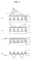
- Figure 3 is a process chart for explaining the method for producing the fluorescent surface of plasma display panel according to the present invention. First, a flow (scheme) of the method according to the present invention is explained in reference of Figure 3.
- the granules 20 described above and a mask sheet 30 having a plurality through holes 31, in which the granules 20 can be retained are used.
- a substrate 12 (vide Figure 1), which constitutes the plasma display panel and has a barrier 13 formed on it, is mounted with its surface having cells 14 faced upwards. Further, the mask sheet 30 is arranged so that the through holes 31 are positioned over the cells 14, in which fluorescent surfaces on the substrate are to be provided.
- the mask sheet 30 allows the granules 20 to be retained in the through holes 31, which are formed in the mask sheet 30.
- Such the producing method according to the present invention is a completely novel method different from a screen printing method using a conventional silkscreen printing mask. Accordingly, it is possible to form a uniform fluorescent surface 15 without causing printing unevenness even in these days when fineness of cells is advancing.
- a shape of mask sheet 30 is not specifically limited to that shown in Figure 3 as long as a through hole 31 is formed in the mask sheet 30 so that granules are retained for a predetermined time (specifically a time while the granules 20 are melted).
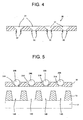
- a guide protrusion 32 may be formed on a surface of the mask sheet 30, opposite to a side where the granules 20 are retained, so that the guide protrusion 32 guides the granule which drops into a predetermined cell through the through hole 31.
- This process is to retain the granule 20 into the through hole 31 by dispersing the granule 20 onto a surface of the mask sheet thus mounted.
- a means for dispersing the granule 20 is not specifically limited in the present invention. Any means can be used as long as the granule 20 can be retained into the through hole 31, formed in the mask sheet 30.
- the granules 20 may be dispersed onto the mask sheet 30 with use of, for example, a spraying device, and vibrates the mask sheet with use of a vibrating device(not shown), to thereby securely retain the granules 20 thus dispersed into the through hole 31 on the mask sheet.
- an extra granule 20, i. e. the granule 20 remaining in the surface of mask sheet 30 without being retained in the through hole 31, can be recovered by an appropriate means and reused.
- a means for recovering the extra granules is not specifically limited. For example, the recovery is enabled to cant the mask sheet 30. However, when if the extra granules 20 are recovered, it is necessary to maintain the granules 20, retained in the through holes 31 that are once retained, as is.
- Figure 5 shows a mode of carrying out the invention other than the process (b) shown in Figure 3.
- the present invention is not specifically limited with respect to a method for retaining the fluorescent substances 20 of these colors into the predetermined through holes 31.
- the above-described fluorescent substances 20 in which any one or both of an electric charge material and a magnetic material are dispersed and blended may be used to utilize electrostatic force or magnetic fore, thereby selectively retaining the fluorescent substance 20 into the predetermined through hole 31.
- a fluorescent substance 20 into which an electric charge material is dispersed and blended it is possible to electrize the fluorescent substance 20 (e.g. red fluorescent substance 20R) to any one of plus and minus.
- the green fluorescent substance 20G is dispersed, thereby enabling the green fluorescent substance 20G to retain only into the through holes of green color 31G in a manner similar to the above process.
- the blue fluorescent substance 31B can be retained into the through holes 31B.
- FIG 6 shows another mode of carrying out the process (b) shown in Figure 3 of the present invention.
- a barometric pressure on a back side (facing the substrate) of the mask sheet 30 may be less than a barometric pressure on a front side (a side on which the substrate is provided) of mask sheet 30.
- This process is to melt the granules 20 which are under a state of being retained in the through holes 31, and to make the granules 20 thus melted drop into the cells 14 which are formed in the substrate and positioned under the mask sheet 30.
- a heating method and a heating means are not specifically limited as long as the granules can be heated up to about a melting temperature, for example, 50 to 180 degrees C.
- a melting temperature for example, 50 to 180 degrees C.
- the barometric pressure on the front side of the mask sheet 30 i.e. the side on which the substrate is not mounted
- the back side of the mask sheet 30 i.e. the side to which the substrate faces
- This process is to vaporize the organic binder 21, which is contained in the granule 20 thus liquidized, and simultaneously solidify the fluorescent substance 22, which is contained in the liquid thus dropped, by heating the substrate 12 where the granule 20 thus liquidized is dropped, to thereby provide the fluorescent surface 15 inside the cell 14.
- the heating method and heating means with respect to the substrate 12 are not specifically limited. Any method and any means may be used as long as the organic binder 21 and the fluorescent substance 22 can be heated up to a temperature (specifically, for example 400 to 500 degree C) of enabling vaporization of the organic binder and solidification of the fluorescent substance 22.
- the process shown in Figure 3(c) and this process shown in Figure 3(d), namely the process of heating to melt the granule 20 retained in the through hole 31 of mask sheet 30 and the process of heating to form the fluorescent surface 15, may be simultaneously carried out.
- the process shown in Figure 3(c) and this process shown in Figure 3(d) are separately carried out, it is inferred that the mask sheet 30 is deformed by thermal expansion or the like in the heating step (i. e. heating to melt the granule 20) of the process shown in Figure 3(c).
- the process shown in Figure 3(c) and this process shown in Figure 3(d) are separately carried out, it is inferred that the mask sheet 30 is deformed by thermal expansion or the like in the heating step (i. e. heating to melt the granule 20) of the process shown in Figure 3(c).
- a positional relationship between the through hole 31 in the mask sheet 30 and the cell 14 on the substrate could be misaligned to prevent the granule 20 thus melted from dropping into
- the granule and the method for producing a fluorescent surface of plasma display panel using the granule of the present invention it is possible to produce, easier and in a shorter time, the fluorescent surface having less unevenness, in comparison with the conventional technique.
Landscapes
- Chemical & Material Sciences (AREA)
- Engineering & Computer Science (AREA)
- Materials Engineering (AREA)
- Organic Chemistry (AREA)
- Inorganic Chemistry (AREA)
- Formation Of Various Coating Films On Cathode Ray Tubes And Lamps (AREA)
- Gas-Filled Discharge Tubes (AREA)
- Luminescent Compositions (AREA)
Abstract
To provide a novel method for forming a plasma display panel and a granule used for this method.
A granule containing an organic binder as an auxiliary forming component, and a fluorescent substance dispersed and blended into the organic binder is used; such the granules and a mask sheet having a plurality of through holes for retaining the granules are prepared; a substrate having a barrier formed on it is mounted with its surface having the cells faced upwards; the mask sheet is disposed above the cells where fluorescent surfaces are to be formed on the substrate thus mounted; the granules are dispersed over a surface of the mask sheet thus disposed to retain the granules in the through holes provided in the mask sheet; the granules thus retained are heated to thereby melt the granules and make the liquefied granule thus obtained drop inside the cells on the substrate using the through holes; and the substrate having the liquefied granule thus dropped on it is heated to vaporize the organic binder contained in the liquefied granule thus dropped and to simultaneously form the fluorescent surface inside the cells by the fluorescent substance contained in the liquefied granule thus dropped.
Description
- The present invention relates to a granule used in forming a fluorescent surface of plasma display panel and a method for forming the fluorescent surface of plasma display panel.
- Figure 1 is a cross-sectional view for illustrating a structure of plasma display panel.
- As shown in Figure 1, a
plasma display panel 10 is constituted by afirst substrate 11 and asecond substrate 12 which are disposed in parallel and opposite to each other. On any one of surfaces on thesesubstrates 11 and 12 (second substrate 12 in Figure 1), abarrier 13 is provided. A cell 14 (sub pixel) is formed as a display element. A fluorescent surface 15 (15R, 15G, 15B) made from a fluorescent substance for generating fluorescence of, for example, red (R), green (G), and blue (B) is provided inside thecell 14.Electrodes first substrate 11 and thesecond substrate 12 for discharging electricity inside thecell 14. - A technique utilized now, as a method of forming such a
fluorescent surface 15 forplasma display panels 10, is to print fluorescent paints of red color (R), green color (G), and blue color (B)in paste form by a screen printing and so on, and thereafter dry and bake the fluorescent paints. - However, when the
fluorescent surface 15 is formed by a screen printing or the like, it is difficult to simultaneously print three colors of red (R), green (G), and blue (B). Therefore, it is necessary to form afluorescent surface 15R of red color (R) by printing and drying a red fluorescent paint, then form afluorescent surface 15G of green color (G) by printing and drying a green fluorescent paint, and then form afluorescent surface 15B of blue color (B) by printing and drying a blue fluorescent paint. Substantial time and labor are required in separately providing each of the colors like that manner. - Further, when the screen printing is employed, a mask for silk screen printing is ordinarily used as a printing mask. In consideration of recent fineness of cells, there is concern for unevenness in printing.
- The present invention is provided in consideration of the above situations. An illustrative object of the present invention is to provide a novel method for forming a fluorescent surface of plasma display panel, the method being different from a conventional method, and a novel granule used for this method.
- To solve the above problems, the invention recited in Claim 1 is about a granule having characteristics that an organic binder is used as an auxiliary forming component and a fluorescent substance is dispersed and blended.
- Further, in order to solve the above problems, the invention recited in Claim 4 is related to a method of forming a fluorescent surface of a plasma display panel having a plurality of cells as display elements provided in it, the cells being formed by barriers provided on any one of first and second substrates, which are disposed in parallel and opposite to each other, and the cells also being provided with the fluorescent surfaces made from a fluorescent substance in the plurality of cells, the method including steps of:
- preparing the granules according to claim 1 and a mask sheet having a plurality of through holes, which can retain the granules, formed in it;
- mounting the substrate having the barrier formed on it with its surface having the cells faced upwards;
- disposing the mask sheet above the cells where fluorescent surfaces are to be formed on the substrate thus mounted;
- dispersing the granules over a surface of the mask sheet thus disposed to retain the granules in the through holes provided in the mask sheet;
- heating the granules thus retained to melt the granules and make the liquefied granule thus obtained drop inside the cells on the substrate using the through holes; and
- heating the substrate having the liquefied granule thus dropped on it to vaporize the organic binder contained in the liquefied granule thus dropped and to simultaneously form the fluorescent surface inside the cells by the fluorescent substance contained in the liquefied granule thus dropped.
-
- [Figure 1] A schematic cross-sectional view for explaining a structure of plasma display panel
- [Figure 2] A schematic cross-sectional view for explaining a
granule 20 according to the present invention - [Figure 3] A process chart for explaining a method for producing a fluorescent surface of display panel according to the present invention
- [Figure 4] A cross-sectional view of a mask sheet used in a producing method of a fluorescent surface of plasma display panel according to the present invention
- [Figure 5] A view for showing another embodiment of process (b) in Figure 3
- [Figure 6] A view for showing another embodiment of process (b) in Figure 3
- Major numerical references denote as follows.
10: plasma display panel; 11 : first substrate; 12: second substrate; 13: barrier; 14: cell (subpixel); 14R: cell provided with red fluorescent surface; 14G: cell provided with green fluorescent surface; 14B: cell provided with blue fluorescent surface; 15: fluorescent surface; 15R: red fluorescent surface; 15G: green fluorescent surface; 15B: blue fluorescent surface; 16,17: electrode; 20: granule; 20R: granule containing red fluorescent substance; 20G: granule containing green fluorescent substance; 20B: granule containing blue fluorescent substance; 21: organic binder; 22: fluorescent substance; 23: electric chargematerial ; 24: magneticmaterial ; 30: mask sheet; 31: through hole; 31R: through hole for retaining red granule(20R); 31G: through hole for retaining green granule (20G) ; 31B: through hole for retaining blue granule (20B); 32: guiding protrusion - A granule according to the present invention is specifically described in reference of the figures.
- Figure 2 is a cross-sectional view schematically showing a
granule 20 according to the present invention. - As shown in Figure 2, the
granule 20 is characterized by having afluorescent substance 22 dispersed and blended into it with use of anorganic binder 21 as an auxiliary forming component. - Such the
granule 20 is preferably used in "a method for forming a fluorescent surface of plasma display panel" described below according to the present invention. Although detail of "a method for forming a fluorescent surface of plasma display panel" according to the present invention will be described later, it is possible to easily provide a fluorescent surface for plasma display panel inside a predetermined cell with use of the granule according to the present invention. Because thegranule 20 is a solid state under an ordinary temperature, it can be easily treated. - An
organic binder 21 constituting thegranule 20 according to the present invention may be any binder as long as a fluorescent substance can be dispersed and blended into it, and further the organic binder can be formed in a granule-like shape. Further, in "a method for forming a fluorescent surface of plasma display panel" according to the present invention, it is necessary to melt the granule during processes of the method. Therefore, it is necessary to melt the granule so as to be in a liquid state by heating it at an adequate temperature (ordinary temperature or more, e.g. 50-180 °C (Celsius)). - Such the
organic binder 21 is specifically acrylic resin, polyester resin, various waxes (e.g. paraffinic wax), and so on. - Further, the
fluorescent substance 22 to be dispersed and blended into the above organic binder itself conclusively becomes a fluorescent surface in a case where the fluorescent surface (15) of plasma display panel (10) is formed in use of for example the granule 20 (vide Figure 1). Accordingly, thefluorescent substance 22 is not specifically limited in the present invention, and it is possible to use all fluorescent substances (specifically fluorescent substances of red color, green color, and blue color), used for forming the fluorescent surfaces for plasma display by now. In an ordinary case, since a fluorescent surface of one color (any one color of RGB) is provided in one cell, thefluorescent substance 22 blended into onegranule 20 has only any one of the colors (any one color of RGB). - Specifically, (YxGd1-x)BO3:Eu 3+ may be used as the red fluorescent substance; Zn2SiO4:Mn2+ may be used as the green fluorescent substance; and BaMgAl10O17:Eu2+ may be used as the blue fluorescent substance.
- Any one or both of an
electric charge material 23 and amagnetic material 24 maybe dispersed and blended into thegranule 20 according to the present invention in addition to the abovefluorescent substance 22. In "a method for forming a fluorescent surface of plasma display panel" described below, by blending theelectric charge material 23 into thegranule 20, it is possible to retain thegranule 20 only in a predetermined through hole formed in the mask sheet with use of an electrostatic force. As a result, it is possible to form a fluorescent surface only in a predetermined cell. In a manner similar thereto, by blending amagnetic material 24 into agranule 20, it is possible to provide a fluorescent surface in only a predetermined cell. - The
electric charge material 23 and themagnetic material 24 are not specifically limited, and may be any material which can demonstrate a function of making thegranule 20 retain only in the predetermined through hole by electrostatic force or magnetic force, and amount of blending these materials are not specifically limited. For example, calcium alkyl benzene sulfonate, dioctyl sodium sulfonate, and styrene- acrylic resin can be mentioned as the electric charge material can be mentioned. Meanwhile, ferrite, magnetite, and rare earths can be mentioned as the magnetic material. - Further, in the
granule 20 according to the present invention, it is possible to blend dispersing agent represented by SiO2 and TiO2 (not shown). Further, an outer surface of thegranule 20 according to the present invention may be coated by a conventional coating material (not shown). By coating the outside, it is possible to avoid coagulation among thegranules 20 and breakage caused by friction. - Size of the
granule 20 according to the present invention is not specifically limited, and can be arbitrarily determined in consideration of size of a through hole provided in a mask material, which is used along with thegranule 20, and size of fluorescent surface in a plasma display panel. Specifically, it is preferably about 100 to 500µm, more preferably 200 to 400µm. Quantity of blendingfluorescent substance 22 with respect to anorganic binder 21 constituting agranule 20 is not specifically limited in the present invention and may arbitrarily be determined in consideration of the size ofgranule 20, the size of fluorescent surface in a plasma display panel, and so on. - Next, a method of producing the fluorescent surface (vide Figure 1) of plasma display panel according to the present invention is described in reference of drawings.
- Figure 3 is a process chart for explaining the method for producing the fluorescent surface of plasma display panel according to the present invention. First, a flow (scheme) of the method according to the present invention is explained in reference of Figure 3.
- In the method of producing the fluorescent surface of display panel according to the present invention, as in Figure 3(a), the
granules 20 described above and amask sheet 30 having a plurality throughholes 31, in which thegranules 20 can be retained, are used. A substrate 12 (vide Figure 1), which constitutes the plasma display panel and has abarrier 13 formed on it, is mounted with itssurface having cells 14 faced upwards. Further, themask sheet 30 is arranged so that the throughholes 31 are positioned over thecells 14, in which fluorescent surfaces on the substrate are to be provided. - Next, as shown in Figure 3(b), by dispersing the
granules 20 on or over themask sheet 30 which is arranged above thecells 14, in which the fluorescent surfaces on thesubstrate 12 are to be provided, themask sheet 30 allows thegranules 20 to be retained in the throughholes 31, which are formed in themask sheet 30. - As shown in Figure 3(c), after melting the
granules 20 thus retained by heating these, a liquid of thus melted granules is dropped into thecells 14 on thesubstrate 12 with use of thethorough holes 31 - Furthermore, as shown in Figure 3(d), by heating the
substrate 12 where the liquid is dropped, theorganic binder 21 contained in the liquid thus dropped is vaporized, and simultaneously thefluorescent substance 22 contained in the liquid thus dropped is solidified, to thereby form the fluorescent surfaces 15 inside thecells 14. - Such the producing method according to the present invention is a completely novel method different from a screen printing method using a conventional silkscreen printing mask. Accordingly, it is possible to form a uniform
fluorescent surface 15 without causing printing unevenness even in these days when fineness of cells is advancing. - Hereinafter, the above-described processes (a) to (d) shown in Figure 3 are described in detail.
- This process is to prepare each of the
granule 20, themask sheet 30, and thesubstrate 12, which are used in the method according to the present invention. Detailed description is not specifically provided. A shape ofmask sheet 30 is not specifically limited to that shown in Figure 3 as long as a throughhole 31 is formed in themask sheet 30 so that granules are retained for a predetermined time (specifically a time while thegranules 20 are melted). For example, as shown in Figure 4, aguide protrusion 32 may be formed on a surface of themask sheet 30, opposite to a side where thegranules 20 are retained, so that theguide protrusion 32 guides the granule which drops into a predetermined cell through the throughhole 31. By providing such theguide protrusions 32, it is possible to more accurately drop the granules thus dropped into the predetermined cells. - This process is to retain the
granule 20 into the throughhole 31 by dispersing thegranule 20 onto a surface of the mask sheet thus mounted. A means for dispersing thegranule 20 is not specifically limited in the present invention. Any means can be used as long as thegranule 20 can be retained into the throughhole 31, formed in themask sheet 30. Specifically, thegranules 20 may be dispersed onto themask sheet 30 with use of, for example, a spraying device, and vibrates the mask sheet with use of a vibrating device(not shown), to thereby securely retain thegranules 20 thus dispersed into the throughhole 31 on the mask sheet. - Further, an
extra granule 20, i. e. thegranule 20 remaining in the surface ofmask sheet 30 without being retained in the throughhole 31, can be recovered by an appropriate means and reused. A means for recovering the extra granules is not specifically limited. For example, the recovery is enabled to cant themask sheet 30. However, when if theextra granules 20 are recovered, it is necessary to maintain thegranules 20, retained in the throughholes 31 that are once retained, as is. - Figure 5 shows a mode of carrying out the invention other than the process (b) shown in Figure 3.
- As shown in Figure 5 according to the present invention, for example, it is preferable to retain a
granule 20R containing a red fluorescent substance, a granule 20G containing a green fluorescent substance, and agranule 20B containing a blue fluorescent substance respectively in through holes 31(i.e. throughholes 31R corresponding to red fluorescent surfaces, throughholes 31G corresponding to green fluorescent surfaces, and throughholes 31B corresponding to blue fluorescent surfaces), which are positioned at predetermined positions on amask sheet 30 and over cells 14 (i.e.cells 14R having a red fluorescent surface,cells 14G having a green fluorescent surface, andcells 14B having a blue fluorescent surface). By retainingfluorescent substances 20 of each color respectively in the predetermined throughholes 31, it becomes possible to finish each of the processes (c) and (d), to be followed , at one clip, thereby enabling to drastically reduce a time for forming fluorescent surfaces of the three colors. - In this, the present invention is not specifically limited with respect to a method for retaining the
fluorescent substances 20 of these colors into the predetermined throughholes 31. For example, "the above-describedfluorescent substances 20 in which any one or both of an electric charge material and a magnetic material are dispersed and blended" may be used to utilize electrostatic force or magnetic fore, thereby selectively retaining thefluorescent substance 20 into the predetermined throughhole 31. Specifically, for example, when afluorescent substance 20 into which an electric charge material is dispersed and blended, it is possible to electrize the fluorescent substance 20 (e.g. redfluorescent substance 20R) to any one of plus and minus. On the other hand, by applying an electric field so that a predetermined through hole 31(31R) in a mask sheet has an electric charge adverse to that offluorescent substance 20, it becomes possible to make thefluorescent substance 20 be retained in only the predetermined through hole 31(31R). Further, under a state where the electric field is applied, extra granules 20(including fluorescent substances retained in through holes, e.g. the through hole for a green color (31G)and the through hole for a blue color (31B)), which do not inherently require retention of granule) may be recovered. Thereafter, it is ceased from applying the electric field to the throughholes 31R for a red color. Under the state that the electric field is applied to the through hole forgreen color 31G, the green fluorescent substance 20G is dispersed, thereby enabling the green fluorescent substance 20G to retain only into the through holes ofgreen color 31G in a manner similar to the above process. In a similar manner thereto, the bluefluorescent substance 31B can be retained into the throughholes 31B. Although the above description is to utilize the electrostatic force in use of thefluorescent substance 20 containing the electro charge material, magnetic force may be utilized along with use of thefluorescent substance 20 in which amagnetic material 20 is contained. - Figure 6 shows another mode of carrying out the process (b) shown in Figure 3 of the present invention.
- In Figures 3(b) and 5, it is shown as if one
fluorescent substance 20 is retained in one throughhole 31. However, as shown in Figure 6, the method of the present invention is not limited to these figures, and a plurality offluorescent substances 20 may be retained into one throughhole 31. When onefluorescent substance 20 is retained in one throughhole 31, it is necessary to prepare thefluorescent substances 20 so that their sizes are accurate to a certain extent because size and thickness of a fluorescent surface to be formed in a substrate is determined by the size offluorescent substance 20. When the plurality offluorescent substances 20 are retained in one throughhole 31, it becomes unnecessary to accurately control the sizes offluorescent substance 20 one by one because an entire amount of the plurality offluorescent substance 20 can be controlled by the size of throughhole 31. Accordingly, it becomes easy to produce thefluorescent substance 20. - Further, in this process, it may be possible to decrease a barometric pressure on a back side (facing the substrate) of the
mask sheet 30 to be less than a barometric pressure on a front side (a side on which the substrate is provided) ofmask sheet 30. By differentiating the barometric pressures on the front and back sides, it is possible to smoothly retain thefluorescent substances 20 in the through holes 31. - This process is to melt the
granules 20 which are under a state of being retained in the throughholes 31, and to make thegranules 20 thus melted drop into thecells 14 which are formed in the substrate and positioned under themask sheet 30. According to the method of the present invention, a heating method and a heating means are not specifically limited as long as the granules can be heated up to about a melting temperature, for example, 50 to 180 degrees C. For example, it is possible to heat the entire mask sheet by an electrically heated wire, which is in advance embedded into themask sheet 30, or carry out the entire process inside a heating chamber. - Further, in a step before carrying out this process and under a state where the fluorescent substances 20(20R, 20G, 20B) of the predetermined colors are mounted respectively in the through holes 31 (31R, 31G, 31B) as shown in Figure 5, it becomes possible to drop the
granules 20 of each color respectively into the cells 14 (14R, 14G, 14B) by carrying out the process only at one clip. - Further, in this process, the barometric pressure on the front side of the mask sheet 30 (i.e. the side on which the substrate is not mounted) may be increased than that on the back side of the mask sheet 30 (i.e. the side to which the substrate faces). By differentiating the barometric pressures on the front and back sides of the
mask sheet 30, it becomes possible to smoothly drop the fluorescent substance thus liquidized. - This process is to vaporize the
organic binder 21, which is contained in thegranule 20 thus liquidized, and simultaneously solidify thefluorescent substance 22, which is contained in the liquid thus dropped, by heating thesubstrate 12 where thegranule 20 thus liquidized is dropped, to thereby provide thefluorescent surface 15 inside thecell 14. In this process, the heating method and heating means with respect to thesubstrate 12 are not specifically limited. Any method and any means may be used as long as theorganic binder 21 and thefluorescent substance 22 can be heated up to a temperature (specifically, for example 400 to 500 degree C) of enabling vaporization of the organic binder and solidification of thefluorescent substance 22. Further, the process shown in Figure 3(c) and this process shown in Figure 3(d), namely the process of heating to melt thegranule 20 retained in the throughhole 31 ofmask sheet 30 and the process of heating to form thefluorescent surface 15, may be simultaneously carried out. When the process shown in Figure 3(c) and this process shown in Figure 3(d) are separately carried out, it is inferred that themask sheet 30 is deformed by thermal expansion or the like in the heating step (i. e. heating to melt the granule 20) of the process shown in Figure 3(c). By this deformation, a positional relationship between the throughhole 31 in themask sheet 30 and thecell 14 on the substrate could be misaligned to prevent thegranule 20 thus melted from dropping into the predetermined cell. However, by simultaneously carrying out the process shown in Figure 3(c) and the process shown in Figure 3(d), possibility of causing such the problem may be lowered. - As described above, according to the granule and the method for producing a fluorescent surface of plasma display panel using the granule of the present invention, it is possible to produce, easier and in a shorter time, the fluorescent surface having less unevenness, in comparison with the conventional technique.
Claims (5)
- A granule comprising:an organic binder as an auxiliary forming component; anda fluorescent substance dispersed and blended into the organic binder.
- The granule according to Claim 1, wherein
any one or both of an electric charge material and a magnetic material are dispersed and blended into the organic binder. - The granule according to Claim 1 or 2, wherein
the fluorescent substance has any one color of red color, blue color, and green color, and is provided to form fluorescent surfaces in cells of plasma display panel. - A method of forming a fluorescent surface of a plasma display panel having a plurality of cells as display elements provided in it, the cells being formed by barriers provided on any one of first and second substrates, which are disposed in parallel and opposite to each other, and the cells also being provided with the fluorescent surfaces made from a fluorescent substance in the plurality of cells, the method comprising steps of:preparing the granules according to claim 1 and a mask sheet having a plurality of through holes, which can retain the granules, formed in it;mounting the substrate having the barrier formed on it with its surface having the cells faced upwards;disposing the mask sheet so that the through holes are positioned above the cells where fluorescent surfaces are to be formed on the substrate thus mounted;dispersing the granules over a surface of the mask sheet thus disposed to retain the granules in the through holes provided in the mask sheet;heating the granules thus retained to melt the granules and make the liquefied granule thus obtained drop inside the cells on the substrate using the through holes; andheating the substrate having the liquefied granule thus dropped on it to vaporize the organic binder contained in the liquefied granule thus dropped and to simultaneously form the fluorescent surface inside the cells by the fluorescent substance contained in the liquefied granule thus dropped.
- A method of forming a fluorescent surface of plasma display panel according to Claim 4, wherein
the granule according to Claim 2 is used instead of the granule according to Claim 1, and
in retaining the granules in the through holes provided in the mask sheet by dispersing the granules on a surface of the mask sheet thus disposed, the granule is selectively retained in a predetermined one of the through holes provided in the mask sheet by using electrostatic force or magnetic force.
Applications Claiming Priority (2)
| Application Number | Priority Date | Filing Date | Title |
|---|---|---|---|
| JP2004198475 | 2004-07-05 | ||
| PCT/JP2005/011836 WO2006003888A1 (en) | 2004-07-05 | 2005-06-28 | Granules, and method of forming fluorescent surface ofplasma display panel using them |
Publications (1)
| Publication Number | Publication Date |
|---|---|
| EP1785463A1 true EP1785463A1 (en) | 2007-05-16 |
Family
ID=35782695
Family Applications (1)
| Application Number | Title | Priority Date | Filing Date |
|---|---|---|---|
| EP05765408A Withdrawn EP1785463A1 (en) | 2004-07-05 | 2005-06-28 | Granules, and method of forming fluorescent surface ofplasma display panel using them |
Country Status (5)
| Country | Link |
|---|---|
| EP (1) | EP1785463A1 (en) |
| JP (1) | JPWO2006003888A1 (en) |
| CN (1) | CN101010403A (en) |
| TW (1) | TW200606990A (en) |
| WO (1) | WO2006003888A1 (en) |
Family Cites Families (3)
| Publication number | Priority date | Publication date | Assignee | Title |
|---|---|---|---|---|
| JP4162162B2 (en) * | 1998-06-08 | 2008-10-08 | 株式会社巴川製紙所 | Method for forming pattern of light-impermeable material and powder used therefor |
| JP2002003835A (en) * | 2000-04-17 | 2002-01-09 | Konica Corp | Inorganic fluorescent substance, dispersing substance of inorganic fluorescent substance and ink for ink jet printer, toner for laser printer, plasma display, electroluminescence apparatus, active luminous liquid crystal apparatus, and image |
| JP2004182841A (en) * | 2002-12-03 | 2004-07-02 | Dainichiseika Color & Chem Mfg Co Ltd | Granular phosphorescent material composition, molding material, molding and masterbatch |
-
2005
- 2005-06-28 WO PCT/JP2005/011836 patent/WO2006003888A1/en not_active Ceased
- 2005-06-28 CN CNA2005800297252A patent/CN101010403A/en active Pending
- 2005-06-28 EP EP05765408A patent/EP1785463A1/en not_active Withdrawn
- 2005-06-28 JP JP2006528707A patent/JPWO2006003888A1/en not_active Withdrawn
- 2005-07-05 TW TW094122667A patent/TW200606990A/en unknown
Non-Patent Citations (1)
| Title |
|---|
| See references of WO2006003888A1 * |
Also Published As
| Publication number | Publication date |
|---|---|
| WO2006003888A1 (en) | 2006-01-12 |
| JPWO2006003888A1 (en) | 2008-07-31 |
| TW200606990A (en) | 2006-02-16 |
| CN101010403A (en) | 2007-08-01 |
Similar Documents
| Publication | Publication Date | Title |
|---|---|---|
| CN101794050B (en) | Color electrophoretic display device and method for manufacturing the same | |
| EP2674810B1 (en) | Electrophoretic display device and method for producing same | |
| US7502162B2 (en) | Core-shell particles containing fluorescent components for electrophoretic displays | |
| EP0623944B1 (en) | Flat panel display apparatus, and method of making same | |
| US20090269703A1 (en) | Color electrophoretic display and method of manufacturing the same | |
| US7862866B2 (en) | Method for forming an electronic paper display | |
| CN108511492A (en) | Organic light-emitting display panel, manufacturing method thereof and organic light-emitting display device | |
| US7262901B2 (en) | Electrophoretic device, method of manufacturing the same, and electronic apparatus | |
| CN1987584A (en) | Method of fabricating liquid crystal display device | |
| CN101246292B (en) | Electronic paper device and manufacturing method thereof | |
| EP1785463A1 (en) | Granules, and method of forming fluorescent surface ofplasma display panel using them | |
| JP2009543292A5 (en) | ||
| EP1760123A2 (en) | Printing ink and phosphor slurry composition, printer and plasma display panel using the same, and method of manufacturing the same | |
| US20050266151A1 (en) | Method for forming phosphor layer on shadow mask of plasma display panel | |
| JP4286286B2 (en) | Method for forming phosphor layer of plasma display panel and method for manufacturing plasma display panel | |
| JP2007157689A (en) | Slurry for partition wall of plasma display panel, green sheet, and partition wall forming method | |
| JP3244483B2 (en) | Method and apparatus for applying phosphor ink to discharge chamber of display panel | |
| Lin et al. | Electrohydrodynamic inkjet printing of perovskite quantum dots for color-conversion micro-LED displays | |
| US7582332B2 (en) | Particles having charge-controlling group on outer surface for electronic-paper display device and method for preparing the same | |
| JP2004240166A (en) | Method of manufacturing image display device | |
| JP2011227440A (en) | Display material enclosing panel manufacturing method, display material enclosing panel, electronic shutter using the same, and image display medium | |
| JP2001314797A (en) | Phosphor coating device and display device manufacturing method | |
| US2938135A (en) | Solid state display screens | |
| JP3817856B2 (en) | Method and apparatus for manufacturing plasma display panel | |
| KR100320223B1 (en) | A Device for producing PDP's low panel with barrier rib and a method thereof |
Legal Events
| Date | Code | Title | Description |
|---|---|---|---|
| PUAI | Public reference made under article 153(3) epc to a published international application that has entered the european phase |
Free format text: ORIGINAL CODE: 0009012 |
|
| 17P | Request for examination filed |
Effective date: 20061229 |
|
| AK | Designated contracting states |
Kind code of ref document: A1 Designated state(s): AT BE BG CH CY CZ DE DK EE ES FI FR GB GR HU IE IS IT LI LT LU MC NL PL PT RO SE SI SK TR |
|
| DAX | Request for extension of the european patent (deleted) | ||
| RAP1 | Party data changed (applicant data changed or rights of an application transferred) |
Owner name: PANASONIC CORPORATION |
|
| STAA | Information on the status of an ep patent application or granted ep patent |
Free format text: STATUS: THE APPLICATION HAS BEEN WITHDRAWN |
|
| 18W | Application withdrawn |
Effective date: 20110405 |