EP1785343A1 - Storage box for a vehicle - Google Patents
Storage box for a vehicle Download PDFInfo
- Publication number
- EP1785343A1 EP1785343A1 EP06123088A EP06123088A EP1785343A1 EP 1785343 A1 EP1785343 A1 EP 1785343A1 EP 06123088 A EP06123088 A EP 06123088A EP 06123088 A EP06123088 A EP 06123088A EP 1785343 A1 EP1785343 A1 EP 1785343A1
- Authority
- EP
- European Patent Office
- Prior art keywords
- top box
- helmet
- holder compartment
- vehicle
- compartment device
- Prior art date
- Legal status (The legal status is an assumption and is not a legal conclusion. Google has not performed a legal analysis and makes no representation as to the accuracy of the status listed.)
- Granted
Links
- 230000001419 dependent effect Effects 0.000 description 1
- 230000004048 modification Effects 0.000 description 1
- 238000012986 modification Methods 0.000 description 1
- 230000001105 regulatory effect Effects 0.000 description 1
Images



Classifications
-
- B—PERFORMING OPERATIONS; TRANSPORTING
- B62—LAND VEHICLES FOR TRAVELLING OTHERWISE THAN ON RAILS
- B62J—CYCLE SADDLES OR SEATS; AUXILIARY DEVICES OR ACCESSORIES SPECIALLY ADAPTED TO CYCLES AND NOT OTHERWISE PROVIDED FOR, e.g. ARTICLE CARRIERS OR CYCLE PROTECTORS
- B62J7/00—Luggage carriers
- B62J7/02—Luggage carriers characterised by the arrangement thereof on cycles
- B62J7/04—Luggage carriers characterised by the arrangement thereof on cycles arranged above or behind the rear wheel
-
- B—PERFORMING OPERATIONS; TRANSPORTING
- B62—LAND VEHICLES FOR TRAVELLING OTHERWISE THAN ON RAILS
- B62J—CYCLE SADDLES OR SEATS; AUXILIARY DEVICES OR ACCESSORIES SPECIALLY ADAPTED TO CYCLES AND NOT OTHERWISE PROVIDED FOR, e.g. ARTICLE CARRIERS OR CYCLE PROTECTORS
- B62J9/00—Containers specially adapted for cycles, e.g. panniers or saddle bags
- B62J9/20—Containers specially adapted for cycles, e.g. panniers or saddle bags attached to the cycle as accessories
- B62J9/23—Containers specially adapted for cycles, e.g. panniers or saddle bags attached to the cycle as accessories above or alongside the rear wheel
-
- B—PERFORMING OPERATIONS; TRANSPORTING
- B62—LAND VEHICLES FOR TRAVELLING OTHERWISE THAN ON RAILS
- B62J—CYCLE SADDLES OR SEATS; AUXILIARY DEVICES OR ACCESSORIES SPECIALLY ADAPTED TO CYCLES AND NOT OTHERWISE PROVIDED FOR, e.g. ARTICLE CARRIERS OR CYCLE PROTECTORS
- B62J9/00—Containers specially adapted for cycles, e.g. panniers or saddle bags
- B62J9/20—Containers specially adapted for cycles, e.g. panniers or saddle bags attached to the cycle as accessories
- B62J9/27—Containers specially adapted for cycles, e.g. panniers or saddle bags attached to the cycle as accessories characterised by mounting arrangements, e.g. quick release arrangements
Definitions
- the present invention relates to an object- and/or helmet-holder compartment device for motor vehicles.
- the invention relates to an object- and/or helmet-holder compartment device commonly known as "top box", studied and produced in particular for reducing the instability of the vehicle generated by traditional top boxes.
- top boxes are object-holder compartments, normally removable and rigid, suitable for containing helmets or other accessories, during journeys or stops.
- Traditional top boxes are generally situated to the rear of the driver or, more specifically, of the passenger being transported.
- top boxes of the known type creates the risk, if the load is excessive, of instability of the vehicle due to the higher position of the top box with respect to the barycentre of the vehicle.
- the rear position of the top box also creates the risk of contact with vehicles or other obstacles and a considerable increase in the encumbrance of the vehicle resulting in greater difficulty in the parking phase.
- An objective of the present invention is therefore to solve the problems of the known art by providing an object- and/or helmet-holder compartment device of the top box type which effectively reduces the instability of vehicles.
- Another objective of the present invention is to provide a top box which improves the aerodynamic coefficient with respect to that of vehicles equipped with top boxes of the traditional type.
- Another objective of the present invention is to provide an object- and/or helmet-holder compartment device which is simple and economical to produce.
- these show an object- and/or helmet-holder compartment device of the top box type, indicated as a whole with 10.
- the compartment device 10 comprises at least one top box 1, at least one guiding element 2, which can be fixed to the vehicle, at least one fixing element 3, fixed to the top box 1 and moving means 5 constrained to the guiding element 2 and fixing means 3.
- the moving means 5 allow the compartment 10 to be moved from a rear position, shown in figure 2, to a forward position, shown in figure 1.
- the top box compartment 10 In a forward position, the top box compartment 10 is situated on the saddle 14 directly behind the driving position, offering the latter a back-rest, see figure 1.
- the movement means 5 comprise at least one sliding block element 6, sliding along the guiding element 2 so as to move the top box 1, substantially along a horizontal line parallel to the advance direction of the vehicle, between a rear position, shown in figure 2, and a forward position, shown in figure 1, and vice versa.
- the guiding element 2 consists of two rails 11, 12 each fixed, to the bodywork of the vehicle, to the side of the saddle 14.
- the rails 11, 12 are fixed to the bodywork of the vehicle by known means commonly used in the field and for this reason are not additionally described.
- the sliding block element 6 consists of two skids 13 each engaged to slide along a guiding rail 11, 12.
- the two skids 13, moreover, are fixed by fixing means 3 to the top box 10, in particular in correspondence with the bottom of the latter.
- the fixing means 3 are in turn represented by a supporting plate, not directly visible in the figure, releasably constrained to the bottom of the top box compartment 1, but they could be represented by pins or bolts directly engaged with the bottom of the top box 1.
- stopping means suitable for fixing the position of the top box 1 in a forward position, shown in figure 1, or in a rear position, shown in figure 2.
- Figures 5 to 8 show another embodiment of the present invention in which however the movement means 5 are represented by at least one connecting rod element 15 fulcrumed at the guiding element 2 and fixing means 3.
- the guiding element 2 has two shaped brackets 21, each fixed to the bodywork of the vehicle, to the side of the saddle 14.
- the shaped brackets 21 are fixed to the bodywork of the vehicle by known means commonly used in the field and for this reason not further described.
- the shaped brackets 21 have a triangular form whose vertex offers the hinging point 28 of the connecting rod element 15.
- the connecting rod element 15 consists of two vertical bars 23, each hinged to a shaped bracket 21 and a structural stiffening transversal bar.
- Each vertical bar 23 is therefore hinged at one end to the relative bracket 21 in correspondence with the vertex of the latter (hinging point 28), and at the other end to the fixing means 3.
- the fixing means 3 comprise a supporting plate 27, which can be releasably constrained to the bottom of the top box 10.
- the bars 23 rotate around the hinging point 28 to move the object-holder top box 1 from the rear position shown in figure 5, with a dashed line, to the forward position, shown in figure 5 with a full line.
- the supporting plate 27 comprises at least two tilting portions 29, 30 suitable for defining two stop elements for the forward and rear position respectively of the top box 1.
- the two tilting portions 29, 30 correspond to the tilting portions of the brackets 21.
- object-holder compartment device can also be produced by providing, as movement means, a series of perforations suitable for being engaged with the fixing means 3.
- the perforations are sequentially arranged on the guiding element 2 which in this case is represented by a plate constrained to the bodywork of the vehicle.
- the fixing means can be represented by screw pins or bolts suitable for releasably constraining the compartment to the guiding element in correspondence with the perforation selected.
Landscapes
- Engineering & Computer Science (AREA)
- Mechanical Engineering (AREA)
- Vehicle Step Arrangements And Article Storage (AREA)
- Warehouses Or Storage Devices (AREA)
- Electrotherapy Devices (AREA)
- Infusion, Injection, And Reservoir Apparatuses (AREA)
- Input Circuits Of Receivers And Coupling Of Receivers And Audio Equipment (AREA)
- Helmets And Other Head Coverings (AREA)
Abstract
Description
- The present invention relates to an object- and/or helmet-holder compartment device for motor vehicles.
- More specifically, the invention relates to an object- and/or helmet-holder compartment device commonly known as "top box", studied and produced in particular for reducing the instability of the vehicle generated by traditional top boxes.
- As known, traditional top boxes are object-holder compartments, normally removable and rigid, suitable for containing helmets or other accessories, during journeys or stops.
- Traditional top boxes are generally situated to the rear of the driver or, more specifically, of the passenger being transported.
- The use of top boxes of the known type creates the risk, if the load is excessive, of instability of the vehicle due to the higher position of the top box with respect to the barycentre of the vehicle.
- Furthermore, with an increased distance between the concentrated weight of the top box and the barycentre of the vehicle, there is a significant reduction in the speed aerodynamics and manageability in city traffic.
- The rear position of the top box also creates the risk of contact with vehicles or other obstacles and a considerable increase in the encumbrance of the vehicle resulting in greater difficulty in the parking phase.
- In view of what is specified above, there is evidently the necessity of an object- and/or helmet-holder compartment of the top box type, such as that of the present invention, which allows an improvement in the aerodynamic coefficient with respect to that of vehicles equipped with compartments of the traditional type.
- An objective of the present invention is therefore to solve the problems of the known art by providing an object- and/or helmet-holder compartment device of the top box type which effectively reduces the instability of vehicles.
- Another objective of the present invention is to provide a top box which improves the aerodynamic coefficient with respect to that of vehicles equipped with top boxes of the traditional type.
- Another objective of the present invention is to provide an object- and/or helmet-holder compartment device which is simple and economical to produce.
- These and other objectives are achieved with the object- and/or helmet-holder compartment device of the top box type according to the present invention which has the characteristics of the enclosed
claim 1. - Further characteristics of the device are object of the dependent claims.
- The characteristics and advantages of an object- and/or helmet-holder compartment device of the top box type according to the present invention will appear more evident from the following illustrative and nonlimiting description, referring to the enclosed schematic drawings, in which:
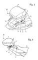
- figure 1 is a side schematic sectional view of a first embodiment of the object- and/or helmet-holder compartment device of the top box type in a forward position according to the present invention;
- figure 2 is a side schematic sectional view of a first embodiment of the object- and/or helmet-holder compartment of the top box type in a rear position according to the present invention;
- figure 3 is a side schematic sectional view of a first embodiment of the object- and/or helmet-holder compartment device of the top box type in an forward position according to the present invention;
- figure 4 is a side schematic sectional view of a first embodiment of the object- and/or helmet-holder compartment device of the top box type in an forward position according to the present invention;
- figure 5 is a side schematic sectional view of a second embodiment of the object- and/or helmet-holder compartment device of the top box type in a rear position according to the present invention;
- figure 6 is a side schematic view of the supporting plate in a rear position;
- figure 7 is a side schematic view of the supporting plate when being transferred to a forward position;
- figure 8 is a side schematic view of the supporting plate in a forward position.
- With reference to the figures, these show an object- and/or helmet-holder compartment device of the top box type, indicated as a whole with 10.
- The
compartment device 10 comprises at least onetop box 1, at least one guidingelement 2, which can be fixed to the vehicle, at least onefixing element 3, fixed to thetop box 1 and moving means 5 constrained to the guidingelement 2 and fixing means 3. - Advantageously according to the present invention, the moving means 5, allow the
compartment 10 to be moved from a rear position, shown in figure 2, to a forward position, shown in figure 1. - In a forward position, the
top box compartment 10 is situated on thesaddle 14 directly behind the driving position, offering the latter a back-rest, see figure 1. - In this position, the distance between the application point of the weight force of the
top box 1 and the barycentre of the vehicle is reduced, at the same time increasing the aerodynamics and manageability of the vehicle. - Vice versa, if necessary, it is possible to move the
top box 1 to the rear position, to obtain space on thesaddle 14 for a second passenger, see figure 2 or 5. - For this purpose, according to a first embodiment shown in figures 1 to 4, the movement means 5 comprise at least one sliding
block element 6, sliding along the guidingelement 2 so as to move thetop box 1, substantially along a horizontal line parallel to the advance direction of the vehicle, between a rear position, shown in figure 2, and a forward position, shown in figure 1, and vice versa. - More specifically, the guiding
element 2 consists of tworails saddle 14. - The
rails - The sliding
block element 6 consists of twoskids 13 each engaged to slide along a guidingrail - The two
skids 13, moreover, are fixed by fixing means 3 to thetop box 10, in particular in correspondence with the bottom of the latter. - The
fixing means 3 are in turn represented by a supporting plate, not directly visible in the figure, releasably constrained to the bottom of thetop box compartment 1, but they could be represented by pins or bolts directly engaged with the bottom of thetop box 1. - There are also stopping means, not shown, suitable for fixing the position of the
top box 1 in a forward position, shown in figure 1, or in a rear position, shown in figure 2. - Figures 5 to 8 show another embodiment of the present invention in which however the movement means 5 are represented by at least one connecting
rod element 15 fulcrumed at the guidingelement 2 and fixing means 3. - In this case, the guiding
element 2 has twoshaped brackets 21, each fixed to the bodywork of the vehicle, to the side of thesaddle 14. - The
shaped brackets 21 are fixed to the bodywork of the vehicle by known means commonly used in the field and for this reason not further described. - As better illustrated in figures 5 to 8, the
shaped brackets 21 have a triangular form whose vertex offers thehinging point 28 of the connectingrod element 15. - More specifically, in the preferred embodiment shown in figures 5 to 8, the connecting
rod element 15 consists of twovertical bars 23, each hinged to ashaped bracket 21 and a structural stiffening transversal bar. - Each
vertical bar 23 is therefore hinged at one end to therelative bracket 21 in correspondence with the vertex of the latter (hinging point 28), and at the other end to the fixing means 3. - The fixing means 3 comprise a supporting
plate 27, which can be releasably constrained to the bottom of thetop box 10. - The
bars 23 rotate around thehinging point 28 to move the object-holder top box 1 from the rear position shown in figure 5, with a dashed line, to the forward position, shown in figure 5 with a full line. - Advantageously according to the present invention, the supporting
plate 27 comprises at least two tiltingportions top box 1. - The two tilting
portions brackets 21. - It should be pointed out however that the object-holder compartment device according to the present invention can also be produced by providing, as movement means, a series of perforations suitable for being engaged with the
fixing means 3. - In this case, the perforations are sequentially arranged on the guiding
element 2 which in this case is represented by a plate constrained to the bodywork of the vehicle. - The fixing means can be represented by screw pins or bolts suitable for releasably constraining the compartment to the guiding element in correspondence with the perforation selected.
- The characteristics of the object- and/or helmet-holder compartment of the "top box" type, object of the present invention, are evident from the above description, as also the relative advantages, among which the following can be mentioned:
- increase in the aerodynamic coefficient of the vehicle;
- reduced risks of contact with other vehicles or obstacles;
- increased manageability of the vehicle;
- constructive simplicity and functionality;
- relatively low production costs;
- possibility of regulating the position of the top box in relation to the necessity of the user.
Claims (10)
- An object- and/or helmet-holder compartment device (10) of the top box type characterized in that it comprises at least one top box (1), at least one guiding element (2) which can be fixed to the vehicle, at least one fixing element (3), fixed to the said top box (1) and moving means (5) constrained to the said guiding element (2) and said fixing means (3) for moving said top box (1) from a rear position to a forward position and vice versa.
- The object- and/or helmet-holder compartment device (10) of the top box type according to claim 1, characterized in that said movement means (5) comprise at least one sliding block element (6), sliding along said guiding element (2) so as to move said compartment (10) between a rear position and a forward position and vice versa.
- The object- and/or helmet-holder compartment device (10) of the top box type according to claim 2, characterized in that said guiding element (2) comprises two rails (11) each fixed to the bodywork of the vehicle to the side of the saddle (14).
- The object- and/or helmet-holder compartment device (10) of the top box type according to claim 3, characterized in that it comprises two skids (13) each sliding on one of said guiding rails (11).
- The object- and/or helmet-holder compartment device (10) of the top box type according to claim 4, characterized in that said two skids (13) are fixed by means of said fixing means (3) to said top box (1).
- The object- and/or helmet-holder compartment device (10) of the top box type according to claim 5, characterized in that said movement means (5) comprise at least one connecting rod element (15) fulcrumed at said guiding element (2) and said fixing means (3).
- The object- and/or helmet-holder compartment (10) according to claim 6, characterized in that said guiding element (2) comprises two shaped brackets (21) each fixed to the bodywork of the vehicle, to the side of the saddle (14).
- The object- and/or helmet-holder compartment (10) according to claim 7, characterized in that said connecting rod element (15) consists of two vertical bars (23), each hinged to a shaped bracket (21) and a transversal bar.
- The object- and/or helmet-holder compartment device (10) according to claim 7, characterized in that said fixing means (3) comprise a supporting plate, which can be releasably constrained to the bottom of the top box (10) and hinged to said connecting rod element (15).
- The object- and/or helmet-holder compartment device (10) according to claim 9, characterized in that said supporting plate comprises at least two tilting portions to define two stop elements for the forward and rear position of said compartment (10).
Applications Claiming Priority (1)
| Application Number | Priority Date | Filing Date | Title |
|---|---|---|---|
| IT002155A ITMI20052155A1 (en) | 2005-11-11 | 2005-11-11 | E-O CARRIER COMPARTMENT COMPARTMENT DEVICE |
Publications (2)
| Publication Number | Publication Date |
|---|---|
| EP1785343A1 true EP1785343A1 (en) | 2007-05-16 |
| EP1785343B1 EP1785343B1 (en) | 2008-10-15 |
Family
ID=37651176
Family Applications (1)
| Application Number | Title | Priority Date | Filing Date |
|---|---|---|---|
| EP06123088A Not-in-force EP1785343B1 (en) | 2005-11-11 | 2006-10-27 | Storage box for a vehicle |
Country Status (7)
| Country | Link |
|---|---|
| EP (1) | EP1785343B1 (en) |
| CN (1) | CN1962346A (en) |
| AT (1) | ATE411213T1 (en) |
| DE (1) | DE602006003171D1 (en) |
| ES (1) | ES2317447T3 (en) |
| IT (1) | ITMI20052155A1 (en) |
| TW (1) | TW200734232A (en) |
Cited By (3)
| Publication number | Priority date | Publication date | Assignee | Title |
|---|---|---|---|---|
| JP2013075552A (en) * | 2011-09-29 | 2013-04-25 | Honda Motor Co Ltd | Saddle type vehicle |
| EP3191359A1 (en) * | 2014-09-09 | 2017-07-19 | Perri, Nicola | Device for mounting a top box to a motorcycle |
| DE102016220296A1 (en) * | 2016-10-18 | 2018-04-19 | Bayerische Motoren Werke Aktiengesellschaft | Rotatable connection arrangement for top case |
Families Citing this family (5)
| Publication number | Priority date | Publication date | Assignee | Title |
|---|---|---|---|---|
| US20110316314A1 (en) * | 2010-06-29 | 2011-12-29 | Barry Brown | Integrated adjustable backrest and storage unit |
| WO2020053797A1 (en) * | 2018-09-13 | 2020-03-19 | Piaggio & C. S.P.A. | Easy-installation top box for ridable saddle vehicle |
| CN112758220B (en) * | 2019-11-04 | 2022-07-19 | 光阳工业股份有限公司 | motorcycle luggage |
| WO2023285854A1 (en) * | 2021-07-12 | 2023-01-19 | Dingo Co., Ltd. | Multi-purpose grab handle system for a motorcycle |
| CN114030551B (en) * | 2021-11-11 | 2023-01-13 | 重庆宗申创新技术研究院有限公司 | Quick power transmission bicycle |
Citations (3)
| Publication number | Priority date | Publication date | Assignee | Title |
|---|---|---|---|---|
| US3625405A (en) * | 1969-06-23 | 1971-12-07 | Newton P Kezar | Carrier and bracket assembly for motorcycles |
| US4266703A (en) | 1980-01-28 | 1981-05-12 | Reuben Litz | Slide mount for motorcycle luggage box |
| US6817501B1 (en) * | 2003-01-28 | 2004-11-16 | Max Rogers | Motorcycle pack support assembly, extension kit and method |
-
2005
- 2005-11-11 IT IT002155A patent/ITMI20052155A1/en unknown
-
2006
- 2006-10-27 EP EP06123088A patent/EP1785343B1/en not_active Not-in-force
- 2006-10-27 AT AT06123088T patent/ATE411213T1/en not_active IP Right Cessation
- 2006-10-27 ES ES06123088T patent/ES2317447T3/en active Active
- 2006-10-27 DE DE602006003171T patent/DE602006003171D1/en not_active Expired - Fee Related
- 2006-11-02 TW TW095140568A patent/TW200734232A/en unknown
- 2006-11-10 CN CNA2006101463453A patent/CN1962346A/en active Pending
Patent Citations (3)
| Publication number | Priority date | Publication date | Assignee | Title |
|---|---|---|---|---|
| US3625405A (en) * | 1969-06-23 | 1971-12-07 | Newton P Kezar | Carrier and bracket assembly for motorcycles |
| US4266703A (en) | 1980-01-28 | 1981-05-12 | Reuben Litz | Slide mount for motorcycle luggage box |
| US6817501B1 (en) * | 2003-01-28 | 2004-11-16 | Max Rogers | Motorcycle pack support assembly, extension kit and method |
Cited By (4)
| Publication number | Priority date | Publication date | Assignee | Title |
|---|---|---|---|---|
| JP2013075552A (en) * | 2011-09-29 | 2013-04-25 | Honda Motor Co Ltd | Saddle type vehicle |
| EP3191359A1 (en) * | 2014-09-09 | 2017-07-19 | Perri, Nicola | Device for mounting a top box to a motorcycle |
| DE102016220296A1 (en) * | 2016-10-18 | 2018-04-19 | Bayerische Motoren Werke Aktiengesellschaft | Rotatable connection arrangement for top case |
| US10988196B2 (en) | 2016-10-18 | 2021-04-27 | Bayerische Motoren Werke Aktiengesellschaft | Rotatable connecting assembly for a top case |
Also Published As
| Publication number | Publication date |
|---|---|
| DE602006003171D1 (en) | 2008-11-27 |
| ES2317447T3 (en) | 2009-04-16 |
| ATE411213T1 (en) | 2008-10-15 |
| ITMI20052155A1 (en) | 2007-05-12 |
| EP1785343B1 (en) | 2008-10-15 |
| TW200734232A (en) | 2007-09-16 |
| CN1962346A (en) | 2007-05-16 |
Similar Documents
| Publication | Publication Date | Title |
|---|---|---|
| EP3470314B1 (en) | Motor scooter | |
| CN211075739U (en) | Vehicle luggage carrier assembly | |
| CN105346469B (en) | Bracket system for vehicle | |
| JP4637878B2 (en) | vehicle | |
| CN105270274B (en) | Bicycle tray for vehicle | |
| US9352714B2 (en) | Adjustable side under-ride guard for sliding axle trailer | |
| US6374934B1 (en) | One-seat motor vehicle | |
| US9854885B2 (en) | Roof box system for motor vehicles and case for a roof box system | |
| EP1785343B1 (en) | Storage box for a vehicle | |
| EP2865560A1 (en) | Side by side all terrain vehicle | |
| KR20100120308A (en) | Motor vehicle with controlled inclination | |
| US11597299B2 (en) | Facing seats-type automated driving vehicle; | |
| KR20140046621A (en) | Personal mobility vehicle | |
| JP2013112096A (en) | Wheel base variable vehicle | |
| US4226466A (en) | Truck, especially a large capacity vehicle or tractor semi-trailer combination | |
| US8905455B2 (en) | Dual-access vehicle drawer system and method | |
| SE1151220A1 (en) | A bed arrangement | |
| US20140077532A1 (en) | Motor vehicle having a roof opening | |
| EP1270381B1 (en) | A cab for a commercial vehicle | |
| US20070080185A1 (en) | Load carrier for vehicle roof | |
| CN104859549A (en) | Stepping mechanism and movable stepping device used for automobile maintenance | |
| DE9402906U1 (en) | Environmentally friendly light vehicle with muscle power drive | |
| CN223031138U (en) | Two-wheel vehicle parking fixing device | |
| EP1985499B1 (en) | Motorcycle carrier | |
| SE527881C2 (en) | load carriers |
Legal Events
| Date | Code | Title | Description |
|---|---|---|---|
| PUAI | Public reference made under article 153(3) epc to a published international application that has entered the european phase |
Free format text: ORIGINAL CODE: 0009012 |
|
| AK | Designated contracting states |
Kind code of ref document: A1 Designated state(s): AT BE BG CH CY CZ DE DK EE ES FI FR GB GR HU IE IS IT LI LT LU LV MC NL PL PT RO SE SI SK TR |
|
| AX | Request for extension of the european patent |
Extension state: AL BA HR MK YU |
|
| 17P | Request for examination filed |
Effective date: 20071016 |
|
| 17Q | First examination report despatched |
Effective date: 20071119 |
|
| AKX | Designation fees paid |
Designated state(s): AT BE BG CH CY CZ DE DK EE ES FI FR GB GR HU IE IS IT LI LT LU LV MC NL PL PT RO SE SI SK TR |
|
| GRAP | Despatch of communication of intention to grant a patent |
Free format text: ORIGINAL CODE: EPIDOSNIGR1 |
|
| GRAS | Grant fee paid |
Free format text: ORIGINAL CODE: EPIDOSNIGR3 |
|
| GRAA | (expected) grant |
Free format text: ORIGINAL CODE: 0009210 |
|
| AK | Designated contracting states |
Kind code of ref document: B1 Designated state(s): AT BE BG CH CY CZ DE DK EE ES FI FR GB GR HU IE IS IT LI LT LU LV MC NL PL PT RO SE SI SK TR |
|
| REG | Reference to a national code |
Ref country code: GB Ref legal event code: FG4D Ref country code: CH Ref legal event code: EP |
|
| REG | Reference to a national code |
Ref country code: IE Ref legal event code: FG4D |
|
| REF | Corresponds to: |
Ref document number: 602006003171 Country of ref document: DE Date of ref document: 20081127 Kind code of ref document: P |
|
| REG | Reference to a national code |
Ref country code: GR Ref legal event code: EP Ref document number: 20090400139 Country of ref document: GR |
|
| NLV1 | Nl: lapsed or annulled due to failure to fulfill the requirements of art. 29p and 29m of the patents act | ||
| REG | Reference to a national code |
Ref country code: ES Ref legal event code: FG2A Ref document number: 2317447 Country of ref document: ES Kind code of ref document: T3 |
|
| PG25 | Lapsed in a contracting state [announced via postgrant information from national office to epo] |
Ref country code: LT Free format text: LAPSE BECAUSE OF FAILURE TO SUBMIT A TRANSLATION OF THE DESCRIPTION OR TO PAY THE FEE WITHIN THE PRESCRIBED TIME-LIMIT Effective date: 20081015 Ref country code: BG Free format text: LAPSE BECAUSE OF FAILURE TO SUBMIT A TRANSLATION OF THE DESCRIPTION OR TO PAY THE FEE WITHIN THE PRESCRIBED TIME-LIMIT Effective date: 20090115 Ref country code: AT Free format text: LAPSE BECAUSE OF FAILURE TO SUBMIT A TRANSLATION OF THE DESCRIPTION OR TO PAY THE FEE WITHIN THE PRESCRIBED TIME-LIMIT Effective date: 20081015 |
|
| PGFP | Annual fee paid to national office [announced via postgrant information from national office to epo] |
Ref country code: ES Payment date: 20090116 Year of fee payment: 3 |
|
| PG25 | Lapsed in a contracting state [announced via postgrant information from national office to epo] |
Ref country code: PT Free format text: LAPSE BECAUSE OF FAILURE TO SUBMIT A TRANSLATION OF THE DESCRIPTION OR TO PAY THE FEE WITHIN THE PRESCRIBED TIME-LIMIT Effective date: 20090316 Ref country code: SI Free format text: LAPSE BECAUSE OF FAILURE TO SUBMIT A TRANSLATION OF THE DESCRIPTION OR TO PAY THE FEE WITHIN THE PRESCRIBED TIME-LIMIT Effective date: 20081015 Ref country code: PL Free format text: LAPSE BECAUSE OF FAILURE TO SUBMIT A TRANSLATION OF THE DESCRIPTION OR TO PAY THE FEE WITHIN THE PRESCRIBED TIME-LIMIT Effective date: 20081015 Ref country code: NL Free format text: LAPSE BECAUSE OF FAILURE TO SUBMIT A TRANSLATION OF THE DESCRIPTION OR TO PAY THE FEE WITHIN THE PRESCRIBED TIME-LIMIT Effective date: 20081015 Ref country code: IS Free format text: LAPSE BECAUSE OF FAILURE TO SUBMIT A TRANSLATION OF THE DESCRIPTION OR TO PAY THE FEE WITHIN THE PRESCRIBED TIME-LIMIT Effective date: 20090215 Ref country code: LV Free format text: LAPSE BECAUSE OF FAILURE TO SUBMIT A TRANSLATION OF THE DESCRIPTION OR TO PAY THE FEE WITHIN THE PRESCRIBED TIME-LIMIT Effective date: 20081015 Ref country code: FI Free format text: LAPSE BECAUSE OF FAILURE TO SUBMIT A TRANSLATION OF THE DESCRIPTION OR TO PAY THE FEE WITHIN THE PRESCRIBED TIME-LIMIT Effective date: 20081015 Ref country code: MC Free format text: LAPSE BECAUSE OF NON-PAYMENT OF DUE FEES Effective date: 20081031 |
|
| PGFP | Annual fee paid to national office [announced via postgrant information from national office to epo] |
Ref country code: DE Payment date: 20090130 Year of fee payment: 3 |
|
| REG | Reference to a national code |
Ref country code: IE Ref legal event code: MM4A |
|
| PG25 | Lapsed in a contracting state [announced via postgrant information from national office to epo] |
Ref country code: RO Free format text: LAPSE BECAUSE OF FAILURE TO SUBMIT A TRANSLATION OF THE DESCRIPTION OR TO PAY THE FEE WITHIN THE PRESCRIBED TIME-LIMIT Effective date: 20081015 Ref country code: BE Free format text: LAPSE BECAUSE OF FAILURE TO SUBMIT A TRANSLATION OF THE DESCRIPTION OR TO PAY THE FEE WITHIN THE PRESCRIBED TIME-LIMIT Effective date: 20081015 Ref country code: DK Free format text: LAPSE BECAUSE OF FAILURE TO SUBMIT A TRANSLATION OF THE DESCRIPTION OR TO PAY THE FEE WITHIN THE PRESCRIBED TIME-LIMIT Effective date: 20081015 Ref country code: EE Free format text: LAPSE BECAUSE OF FAILURE TO SUBMIT A TRANSLATION OF THE DESCRIPTION OR TO PAY THE FEE WITHIN THE PRESCRIBED TIME-LIMIT Effective date: 20081015 |
|
| PLBE | No opposition filed within time limit |
Free format text: ORIGINAL CODE: 0009261 |
|
| STAA | Information on the status of an ep patent application or granted ep patent |
Free format text: STATUS: NO OPPOSITION FILED WITHIN TIME LIMIT |
|
| PG25 | Lapsed in a contracting state [announced via postgrant information from national office to epo] |
Ref country code: SE Free format text: LAPSE BECAUSE OF FAILURE TO SUBMIT A TRANSLATION OF THE DESCRIPTION OR TO PAY THE FEE WITHIN THE PRESCRIBED TIME-LIMIT Effective date: 20090115 Ref country code: CZ Free format text: LAPSE BECAUSE OF FAILURE TO SUBMIT A TRANSLATION OF THE DESCRIPTION OR TO PAY THE FEE WITHIN THE PRESCRIBED TIME-LIMIT Effective date: 20081015 |
|
| 26N | No opposition filed |
Effective date: 20090716 |
|
| PG25 | Lapsed in a contracting state [announced via postgrant information from national office to epo] |
Ref country code: SK Free format text: LAPSE BECAUSE OF FAILURE TO SUBMIT A TRANSLATION OF THE DESCRIPTION OR TO PAY THE FEE WITHIN THE PRESCRIBED TIME-LIMIT Effective date: 20081015 |
|
| PG25 | Lapsed in a contracting state [announced via postgrant information from national office to epo] |
Ref country code: IE Free format text: LAPSE BECAUSE OF NON-PAYMENT OF DUE FEES Effective date: 20081027 |
|
| PGFP | Annual fee paid to national office [announced via postgrant information from national office to epo] |
Ref country code: FR Payment date: 20090130 Year of fee payment: 3 |
|
| PGFP | Annual fee paid to national office [announced via postgrant information from national office to epo] |
Ref country code: IT Payment date: 20091031 Year of fee payment: 4 |
|
| REG | Reference to a national code |
Ref country code: FR Ref legal event code: ST Effective date: 20100630 |
|
| PG25 | Lapsed in a contracting state [announced via postgrant information from national office to epo] |
Ref country code: LU Free format text: LAPSE BECAUSE OF NON-PAYMENT OF DUE FEES Effective date: 20081027 Ref country code: HU Free format text: LAPSE BECAUSE OF FAILURE TO SUBMIT A TRANSLATION OF THE DESCRIPTION OR TO PAY THE FEE WITHIN THE PRESCRIBED TIME-LIMIT Effective date: 20090416 Ref country code: CY Free format text: LAPSE BECAUSE OF FAILURE TO SUBMIT A TRANSLATION OF THE DESCRIPTION OR TO PAY THE FEE WITHIN THE PRESCRIBED TIME-LIMIT Effective date: 20081015 Ref country code: DE Free format text: LAPSE BECAUSE OF NON-PAYMENT OF DUE FEES Effective date: 20100501 Ref country code: FR Free format text: LAPSE BECAUSE OF NON-PAYMENT OF DUE FEES Effective date: 20091102 |
|
| PG25 | Lapsed in a contracting state [announced via postgrant information from national office to epo] |
Ref country code: TR Free format text: LAPSE BECAUSE OF FAILURE TO SUBMIT A TRANSLATION OF THE DESCRIPTION OR TO PAY THE FEE WITHIN THE PRESCRIBED TIME-LIMIT Effective date: 20081015 |
|
| REG | Reference to a national code |
Ref country code: ES Ref legal event code: FD2A Effective date: 20110301 |
|
| REG | Reference to a national code |
Ref country code: CH Ref legal event code: PL |
|
| GBPC | Gb: european patent ceased through non-payment of renewal fee |
Effective date: 20101027 |
|
| PG25 | Lapsed in a contracting state [announced via postgrant information from national office to epo] |
Ref country code: CH Free format text: LAPSE BECAUSE OF NON-PAYMENT OF DUE FEES Effective date: 20101031 Ref country code: LI Free format text: LAPSE BECAUSE OF NON-PAYMENT OF DUE FEES Effective date: 20101031 Ref country code: ES Free format text: LAPSE BECAUSE OF NON-PAYMENT OF DUE FEES Effective date: 20110228 Ref country code: GR Free format text: LAPSE BECAUSE OF NON-PAYMENT OF DUE FEES Effective date: 20110503 |
|
| PG25 | Lapsed in a contracting state [announced via postgrant information from national office to epo] |
Ref country code: GB Free format text: LAPSE BECAUSE OF NON-PAYMENT OF DUE FEES Effective date: 20101027 |
|
| PG25 | Lapsed in a contracting state [announced via postgrant information from national office to epo] |
Ref country code: ES Free format text: LAPSE BECAUSE OF NON-PAYMENT OF DUE FEES Effective date: 20091028 |
|
| PG25 | Lapsed in a contracting state [announced via postgrant information from national office to epo] |
Ref country code: IT Free format text: LAPSE BECAUSE OF NON-PAYMENT OF DUE FEES Effective date: 20101027 |