EP1785326A1 - Vehicle driving assist - Google Patents
Vehicle driving assist Download PDFInfo
- Publication number
- EP1785326A1 EP1785326A1 EP06255698A EP06255698A EP1785326A1 EP 1785326 A1 EP1785326 A1 EP 1785326A1 EP 06255698 A EP06255698 A EP 06255698A EP 06255698 A EP06255698 A EP 06255698A EP 1785326 A1 EP1785326 A1 EP 1785326A1
- Authority
- EP
- European Patent Office
- Prior art keywords
- risk potential
- obstacle
- vehicle
- marker
- targeted
- Prior art date
- Legal status (The legal status is an assumption and is not a legal conclusion. Google has not performed a legal analysis and makes no representation as to the accuracy of the status listed.)
- Granted
Links
Images










Classifications
-
- B—PERFORMING OPERATIONS; TRANSPORTING
- B60—VEHICLES IN GENERAL
- B60K—ARRANGEMENT OR MOUNTING OF PROPULSION UNITS OR OF TRANSMISSIONS IN VEHICLES; ARRANGEMENT OR MOUNTING OF PLURAL DIVERSE PRIME-MOVERS IN VEHICLES; AUXILIARY DRIVES FOR VEHICLES; INSTRUMENTATION OR DASHBOARDS FOR VEHICLES; ARRANGEMENTS IN CONNECTION WITH COOLING, AIR INTAKE, GAS EXHAUST OR FUEL SUPPLY OF PROPULSION UNITS IN VEHICLES
- B60K26/00—Arrangement or mounting of propulsion-unit control devices in vehicles
- B60K26/02—Arrangement or mounting of propulsion-unit control devices in vehicles of initiating means or elements
- B60K26/021—Arrangement or mounting of propulsion-unit control devices in vehicles of initiating means or elements with means for providing feel, e.g. by changing pedal force characteristics
-
- B—PERFORMING OPERATIONS; TRANSPORTING
- B60—VEHICLES IN GENERAL
- B60K—ARRANGEMENT OR MOUNTING OF PROPULSION UNITS OR OF TRANSMISSIONS IN VEHICLES; ARRANGEMENT OR MOUNTING OF PLURAL DIVERSE PRIME-MOVERS IN VEHICLES; AUXILIARY DRIVES FOR VEHICLES; INSTRUMENTATION OR DASHBOARDS FOR VEHICLES; ARRANGEMENTS IN CONNECTION WITH COOLING, AIR INTAKE, GAS EXHAUST OR FUEL SUPPLY OF PROPULSION UNITS IN VEHICLES
- B60K35/00—Instruments specially adapted for vehicles; Arrangement of instruments in or on vehicles
- B60K35/10—Input arrangements, i.e. from user to vehicle, associated with vehicle functions or specially adapted therefor
-
- B—PERFORMING OPERATIONS; TRANSPORTING
- B60—VEHICLES IN GENERAL
- B60K—ARRANGEMENT OR MOUNTING OF PROPULSION UNITS OR OF TRANSMISSIONS IN VEHICLES; ARRANGEMENT OR MOUNTING OF PLURAL DIVERSE PRIME-MOVERS IN VEHICLES; AUXILIARY DRIVES FOR VEHICLES; INSTRUMENTATION OR DASHBOARDS FOR VEHICLES; ARRANGEMENTS IN CONNECTION WITH COOLING, AIR INTAKE, GAS EXHAUST OR FUEL SUPPLY OF PROPULSION UNITS IN VEHICLES
- B60K35/00—Instruments specially adapted for vehicles; Arrangement of instruments in or on vehicles
- B60K35/20—Output arrangements, i.e. from vehicle to user, associated with vehicle functions or specially adapted therefor
- B60K35/21—Output arrangements, i.e. from vehicle to user, associated with vehicle functions or specially adapted therefor using visual output, e.g. blinking lights or matrix displays
- B60K35/22—Display screens
-
- B—PERFORMING OPERATIONS; TRANSPORTING
- B60—VEHICLES IN GENERAL
- B60K—ARRANGEMENT OR MOUNTING OF PROPULSION UNITS OR OF TRANSMISSIONS IN VEHICLES; ARRANGEMENT OR MOUNTING OF PLURAL DIVERSE PRIME-MOVERS IN VEHICLES; AUXILIARY DRIVES FOR VEHICLES; INSTRUMENTATION OR DASHBOARDS FOR VEHICLES; ARRANGEMENTS IN CONNECTION WITH COOLING, AIR INTAKE, GAS EXHAUST OR FUEL SUPPLY OF PROPULSION UNITS IN VEHICLES
- B60K35/00—Instruments specially adapted for vehicles; Arrangement of instruments in or on vehicles
- B60K35/20—Output arrangements, i.e. from vehicle to user, associated with vehicle functions or specially adapted therefor
- B60K35/21—Output arrangements, i.e. from vehicle to user, associated with vehicle functions or specially adapted therefor using visual output, e.g. blinking lights or matrix displays
- B60K35/23—Head-up displays [HUD]
-
- B—PERFORMING OPERATIONS; TRANSPORTING
- B60—VEHICLES IN GENERAL
- B60K—ARRANGEMENT OR MOUNTING OF PROPULSION UNITS OR OF TRANSMISSIONS IN VEHICLES; ARRANGEMENT OR MOUNTING OF PLURAL DIVERSE PRIME-MOVERS IN VEHICLES; AUXILIARY DRIVES FOR VEHICLES; INSTRUMENTATION OR DASHBOARDS FOR VEHICLES; ARRANGEMENTS IN CONNECTION WITH COOLING, AIR INTAKE, GAS EXHAUST OR FUEL SUPPLY OF PROPULSION UNITS IN VEHICLES
- B60K35/00—Instruments specially adapted for vehicles; Arrangement of instruments in or on vehicles
- B60K35/20—Output arrangements, i.e. from vehicle to user, associated with vehicle functions or specially adapted therefor
- B60K35/21—Output arrangements, i.e. from vehicle to user, associated with vehicle functions or specially adapted therefor using visual output, e.g. blinking lights or matrix displays
- B60K35/23—Head-up displays [HUD]
- B60K35/233—Head-up displays [HUD] controlling the size or position in display areas of virtual images depending on the condition of the vehicle or the driver
-
- B—PERFORMING OPERATIONS; TRANSPORTING
- B60—VEHICLES IN GENERAL
- B60K—ARRANGEMENT OR MOUNTING OF PROPULSION UNITS OR OF TRANSMISSIONS IN VEHICLES; ARRANGEMENT OR MOUNTING OF PLURAL DIVERSE PRIME-MOVERS IN VEHICLES; AUXILIARY DRIVES FOR VEHICLES; INSTRUMENTATION OR DASHBOARDS FOR VEHICLES; ARRANGEMENTS IN CONNECTION WITH COOLING, AIR INTAKE, GAS EXHAUST OR FUEL SUPPLY OF PROPULSION UNITS IN VEHICLES
- B60K35/00—Instruments specially adapted for vehicles; Arrangement of instruments in or on vehicles
- B60K35/20—Output arrangements, i.e. from vehicle to user, associated with vehicle functions or specially adapted therefor
- B60K35/25—Output arrangements, i.e. from vehicle to user, associated with vehicle functions or specially adapted therefor using haptic output
-
- B—PERFORMING OPERATIONS; TRANSPORTING
- B60—VEHICLES IN GENERAL
- B60K—ARRANGEMENT OR MOUNTING OF PROPULSION UNITS OR OF TRANSMISSIONS IN VEHICLES; ARRANGEMENT OR MOUNTING OF PLURAL DIVERSE PRIME-MOVERS IN VEHICLES; AUXILIARY DRIVES FOR VEHICLES; INSTRUMENTATION OR DASHBOARDS FOR VEHICLES; ARRANGEMENTS IN CONNECTION WITH COOLING, AIR INTAKE, GAS EXHAUST OR FUEL SUPPLY OF PROPULSION UNITS IN VEHICLES
- B60K35/00—Instruments specially adapted for vehicles; Arrangement of instruments in or on vehicles
- B60K35/20—Output arrangements, i.e. from vehicle to user, associated with vehicle functions or specially adapted therefor
- B60K35/26—Output arrangements, i.e. from vehicle to user, associated with vehicle functions or specially adapted therefor using acoustic output
-
- B—PERFORMING OPERATIONS; TRANSPORTING
- B60—VEHICLES IN GENERAL
- B60K—ARRANGEMENT OR MOUNTING OF PROPULSION UNITS OR OF TRANSMISSIONS IN VEHICLES; ARRANGEMENT OR MOUNTING OF PLURAL DIVERSE PRIME-MOVERS IN VEHICLES; AUXILIARY DRIVES FOR VEHICLES; INSTRUMENTATION OR DASHBOARDS FOR VEHICLES; ARRANGEMENTS IN CONNECTION WITH COOLING, AIR INTAKE, GAS EXHAUST OR FUEL SUPPLY OF PROPULSION UNITS IN VEHICLES
- B60K35/00—Instruments specially adapted for vehicles; Arrangement of instruments in or on vehicles
- B60K35/20—Output arrangements, i.e. from vehicle to user, associated with vehicle functions or specially adapted therefor
- B60K35/28—Output arrangements, i.e. from vehicle to user, associated with vehicle functions or specially adapted therefor characterised by the type of the output information, e.g. video entertainment or vehicle dynamics information; characterised by the purpose of the output information, e.g. for attracting the attention of the driver
-
- B—PERFORMING OPERATIONS; TRANSPORTING
- B60—VEHICLES IN GENERAL
- B60K—ARRANGEMENT OR MOUNTING OF PROPULSION UNITS OR OF TRANSMISSIONS IN VEHICLES; ARRANGEMENT OR MOUNTING OF PLURAL DIVERSE PRIME-MOVERS IN VEHICLES; AUXILIARY DRIVES FOR VEHICLES; INSTRUMENTATION OR DASHBOARDS FOR VEHICLES; ARRANGEMENTS IN CONNECTION WITH COOLING, AIR INTAKE, GAS EXHAUST OR FUEL SUPPLY OF PROPULSION UNITS IN VEHICLES
- B60K35/00—Instruments specially adapted for vehicles; Arrangement of instruments in or on vehicles
- B60K35/20—Output arrangements, i.e. from vehicle to user, associated with vehicle functions or specially adapted therefor
- B60K35/29—Instruments characterised by the way in which information is handled, e.g. showing information on plural displays or prioritising information according to driving conditions
-
- B—PERFORMING OPERATIONS; TRANSPORTING
- B60—VEHICLES IN GENERAL
- B60K—ARRANGEMENT OR MOUNTING OF PROPULSION UNITS OR OF TRANSMISSIONS IN VEHICLES; ARRANGEMENT OR MOUNTING OF PLURAL DIVERSE PRIME-MOVERS IN VEHICLES; AUXILIARY DRIVES FOR VEHICLES; INSTRUMENTATION OR DASHBOARDS FOR VEHICLES; ARRANGEMENTS IN CONNECTION WITH COOLING, AIR INTAKE, GAS EXHAUST OR FUEL SUPPLY OF PROPULSION UNITS IN VEHICLES
- B60K35/00—Instruments specially adapted for vehicles; Arrangement of instruments in or on vehicles
- B60K35/80—Arrangements for controlling instruments
- B60K35/81—Arrangements for controlling instruments for controlling displays
-
- B—PERFORMING OPERATIONS; TRANSPORTING
- B60—VEHICLES IN GENERAL
- B60R—VEHICLES, VEHICLE FITTINGS, OR VEHICLE PARTS, NOT OTHERWISE PROVIDED FOR
- B60R1/00—Optical viewing arrangements; Real-time viewing arrangements for drivers or passengers using optical image capturing systems, e.g. cameras or video systems specially adapted for use in or on vehicles
- B60R1/20—Real-time viewing arrangements for drivers or passengers using optical image capturing systems, e.g. cameras or video systems specially adapted for use in or on vehicles
- B60R1/22—Real-time viewing arrangements for drivers or passengers using optical image capturing systems, e.g. cameras or video systems specially adapted for use in or on vehicles for viewing an area outside the vehicle, e.g. the exterior of the vehicle
- B60R1/23—Real-time viewing arrangements for drivers or passengers using optical image capturing systems, e.g. cameras or video systems specially adapted for use in or on vehicles for viewing an area outside the vehicle, e.g. the exterior of the vehicle with a predetermined field of view
- B60R1/24—Real-time viewing arrangements for drivers or passengers using optical image capturing systems, e.g. cameras or video systems specially adapted for use in or on vehicles for viewing an area outside the vehicle, e.g. the exterior of the vehicle with a predetermined field of view in front of the vehicle
-
- B—PERFORMING OPERATIONS; TRANSPORTING
- B60—VEHICLES IN GENERAL
- B60R—VEHICLES, VEHICLE FITTINGS, OR VEHICLE PARTS, NOT OTHERWISE PROVIDED FOR
- B60R21/00—Arrangements or fittings on vehicles for protecting or preventing injuries to occupants or pedestrians in case of accidents or other traffic risks
- B60R21/01—Electrical circuits for triggering passive safety arrangements, e.g. airbags, safety belt tighteners, in case of vehicle accidents or impending vehicle accidents
- B60R21/013—Electrical circuits for triggering passive safety arrangements, e.g. airbags, safety belt tighteners, in case of vehicle accidents or impending vehicle accidents including means for detecting collisions, impending collisions or roll-over
- B60R21/0134—Electrical circuits for triggering passive safety arrangements, e.g. airbags, safety belt tighteners, in case of vehicle accidents or impending vehicle accidents including means for detecting collisions, impending collisions or roll-over responsive to imminent contact with an obstacle, e.g. using radar systems
-
- B—PERFORMING OPERATIONS; TRANSPORTING
- B60—VEHICLES IN GENERAL
- B60W—CONJOINT CONTROL OF VEHICLE SUB-UNITS OF DIFFERENT TYPE OR DIFFERENT FUNCTION; CONTROL SYSTEMS SPECIALLY ADAPTED FOR HYBRID VEHICLES; ROAD VEHICLE DRIVE CONTROL SYSTEMS FOR PURPOSES NOT RELATED TO THE CONTROL OF A PARTICULAR SUB-UNIT
- B60W40/00—Estimation or calculation of non-directly measurable driving parameters for road vehicle drive control systems not related to the control of a particular sub unit, e.g. by using mathematical models
- B60W40/02—Estimation or calculation of non-directly measurable driving parameters for road vehicle drive control systems not related to the control of a particular sub unit, e.g. by using mathematical models related to ambient conditions
-
- B—PERFORMING OPERATIONS; TRANSPORTING
- B60—VEHICLES IN GENERAL
- B60W—CONJOINT CONTROL OF VEHICLE SUB-UNITS OF DIFFERENT TYPE OR DIFFERENT FUNCTION; CONTROL SYSTEMS SPECIALLY ADAPTED FOR HYBRID VEHICLES; ROAD VEHICLE DRIVE CONTROL SYSTEMS FOR PURPOSES NOT RELATED TO THE CONTROL OF A PARTICULAR SUB-UNIT
- B60W50/00—Details of control systems for road vehicle drive control not related to the control of a particular sub-unit, e.g. process diagnostic or vehicle driver interfaces
- B60W50/08—Interaction between the driver and the control system
- B60W50/14—Means for informing the driver, warning the driver or prompting a driver intervention
- B60W50/16—Tactile feedback to the driver, e.g. vibration or force feedback to the driver on the steering wheel or the accelerator pedal
-
- G—PHYSICS
- G02—OPTICS
- G02B—OPTICAL ELEMENTS, SYSTEMS OR APPARATUS
- G02B27/00—Optical systems or apparatus not provided for by any of the groups G02B1/00 - G02B26/00, G02B30/00
- G02B27/01—Head-up displays
-
- G—PHYSICS
- G06—COMPUTING OR CALCULATING; COUNTING
- G06V—IMAGE OR VIDEO RECOGNITION OR UNDERSTANDING
- G06V20/00—Scenes; Scene-specific elements
- G06V20/50—Context or environment of the image
- G06V20/56—Context or environment of the image exterior to a vehicle by using sensors mounted on the vehicle
- G06V20/58—Recognition of moving objects or obstacles, e.g. vehicles or pedestrians; Recognition of traffic objects, e.g. traffic signs, traffic lights or roads
-
- B—PERFORMING OPERATIONS; TRANSPORTING
- B60—VEHICLES IN GENERAL
- B60K—ARRANGEMENT OR MOUNTING OF PROPULSION UNITS OR OF TRANSMISSIONS IN VEHICLES; ARRANGEMENT OR MOUNTING OF PLURAL DIVERSE PRIME-MOVERS IN VEHICLES; AUXILIARY DRIVES FOR VEHICLES; INSTRUMENTATION OR DASHBOARDS FOR VEHICLES; ARRANGEMENTS IN CONNECTION WITH COOLING, AIR INTAKE, GAS EXHAUST OR FUEL SUPPLY OF PROPULSION UNITS IN VEHICLES
- B60K2360/00—Indexing scheme associated with groups B60K35/00 or B60K37/00 relating to details of instruments or dashboards
- B60K2360/16—Type of output information
- B60K2360/179—Distances to obstacles or vehicles
-
- B—PERFORMING OPERATIONS; TRANSPORTING
- B60—VEHICLES IN GENERAL
- B60K—ARRANGEMENT OR MOUNTING OF PROPULSION UNITS OR OF TRANSMISSIONS IN VEHICLES; ARRANGEMENT OR MOUNTING OF PLURAL DIVERSE PRIME-MOVERS IN VEHICLES; AUXILIARY DRIVES FOR VEHICLES; INSTRUMENTATION OR DASHBOARDS FOR VEHICLES; ARRANGEMENTS IN CONNECTION WITH COOLING, AIR INTAKE, GAS EXHAUST OR FUEL SUPPLY OF PROPULSION UNITS IN VEHICLES
- B60K2360/00—Indexing scheme associated with groups B60K35/00 or B60K37/00 relating to details of instruments or dashboards
- B60K2360/18—Information management
- B60K2360/188—Displaying information using colour changes
-
- B—PERFORMING OPERATIONS; TRANSPORTING
- B60—VEHICLES IN GENERAL
- B60K—ARRANGEMENT OR MOUNTING OF PROPULSION UNITS OR OF TRANSMISSIONS IN VEHICLES; ARRANGEMENT OR MOUNTING OF PLURAL DIVERSE PRIME-MOVERS IN VEHICLES; AUXILIARY DRIVES FOR VEHICLES; INSTRUMENTATION OR DASHBOARDS FOR VEHICLES; ARRANGEMENTS IN CONNECTION WITH COOLING, AIR INTAKE, GAS EXHAUST OR FUEL SUPPLY OF PROPULSION UNITS IN VEHICLES
- B60K2360/00—Indexing scheme associated with groups B60K35/00 or B60K37/00 relating to details of instruments or dashboards
- B60K2360/20—Optical features of instruments
- B60K2360/21—Optical features of instruments using cameras
-
- B—PERFORMING OPERATIONS; TRANSPORTING
- B60—VEHICLES IN GENERAL
- B60K—ARRANGEMENT OR MOUNTING OF PROPULSION UNITS OR OF TRANSMISSIONS IN VEHICLES; ARRANGEMENT OR MOUNTING OF PLURAL DIVERSE PRIME-MOVERS IN VEHICLES; AUXILIARY DRIVES FOR VEHICLES; INSTRUMENTATION OR DASHBOARDS FOR VEHICLES; ARRANGEMENTS IN CONNECTION WITH COOLING, AIR INTAKE, GAS EXHAUST OR FUEL SUPPLY OF PROPULSION UNITS IN VEHICLES
- B60K2360/00—Indexing scheme associated with groups B60K35/00 or B60K37/00 relating to details of instruments or dashboards
- B60K2360/20—Optical features of instruments
- B60K2360/33—Illumination features
- B60K2360/334—Projection means
-
- B—PERFORMING OPERATIONS; TRANSPORTING
- B60—VEHICLES IN GENERAL
- B60R—VEHICLES, VEHICLE FITTINGS, OR VEHICLE PARTS, NOT OTHERWISE PROVIDED FOR
- B60R2300/00—Details of viewing arrangements using cameras and displays, specially adapted for use in a vehicle
- B60R2300/20—Details of viewing arrangements using cameras and displays, specially adapted for use in a vehicle characterised by the type of display used
- B60R2300/205—Details of viewing arrangements using cameras and displays, specially adapted for use in a vehicle characterised by the type of display used using a head-up display
-
- B—PERFORMING OPERATIONS; TRANSPORTING
- B60—VEHICLES IN GENERAL
- B60R—VEHICLES, VEHICLE FITTINGS, OR VEHICLE PARTS, NOT OTHERWISE PROVIDED FOR
- B60R2300/00—Details of viewing arrangements using cameras and displays, specially adapted for use in a vehicle
- B60R2300/30—Details of viewing arrangements using cameras and displays, specially adapted for use in a vehicle characterised by the type of image processing
- B60R2300/301—Details of viewing arrangements using cameras and displays, specially adapted for use in a vehicle characterised by the type of image processing combining image information with other obstacle sensor information, e.g. using RADAR/LIDAR/SONAR sensors for estimating risk of collision
-
- B—PERFORMING OPERATIONS; TRANSPORTING
- B60—VEHICLES IN GENERAL
- B60R—VEHICLES, VEHICLE FITTINGS, OR VEHICLE PARTS, NOT OTHERWISE PROVIDED FOR
- B60R2300/00—Details of viewing arrangements using cameras and displays, specially adapted for use in a vehicle
- B60R2300/30—Details of viewing arrangements using cameras and displays, specially adapted for use in a vehicle characterised by the type of image processing
- B60R2300/307—Details of viewing arrangements using cameras and displays, specially adapted for use in a vehicle characterised by the type of image processing virtually distinguishing relevant parts of a scene from the background of the scene
- B60R2300/308—Details of viewing arrangements using cameras and displays, specially adapted for use in a vehicle characterised by the type of image processing virtually distinguishing relevant parts of a scene from the background of the scene by overlaying the real scene, e.g. through a head-up display on the windscreen
-
- B—PERFORMING OPERATIONS; TRANSPORTING
- B60—VEHICLES IN GENERAL
- B60R—VEHICLES, VEHICLE FITTINGS, OR VEHICLE PARTS, NOT OTHERWISE PROVIDED FOR
- B60R2300/00—Details of viewing arrangements using cameras and displays, specially adapted for use in a vehicle
- B60R2300/80—Details of viewing arrangements using cameras and displays, specially adapted for use in a vehicle characterised by the intended use of the viewing arrangement
- B60R2300/8033—Details of viewing arrangements using cameras and displays, specially adapted for use in a vehicle characterised by the intended use of the viewing arrangement for pedestrian protection
-
- B—PERFORMING OPERATIONS; TRANSPORTING
- B60—VEHICLES IN GENERAL
- B60R—VEHICLES, VEHICLE FITTINGS, OR VEHICLE PARTS, NOT OTHERWISE PROVIDED FOR
- B60R2300/00—Details of viewing arrangements using cameras and displays, specially adapted for use in a vehicle
- B60R2300/80—Details of viewing arrangements using cameras and displays, specially adapted for use in a vehicle characterised by the intended use of the viewing arrangement
- B60R2300/8093—Details of viewing arrangements using cameras and displays, specially adapted for use in a vehicle characterised by the intended use of the viewing arrangement for obstacle warning
-
- B—PERFORMING OPERATIONS; TRANSPORTING
- B60—VEHICLES IN GENERAL
- B60W—CONJOINT CONTROL OF VEHICLE SUB-UNITS OF DIFFERENT TYPE OR DIFFERENT FUNCTION; CONTROL SYSTEMS SPECIALLY ADAPTED FOR HYBRID VEHICLES; ROAD VEHICLE DRIVE CONTROL SYSTEMS FOR PURPOSES NOT RELATED TO THE CONTROL OF A PARTICULAR SUB-UNIT
- B60W50/00—Details of control systems for road vehicle drive control not related to the control of a particular sub-unit, e.g. process diagnostic or vehicle driver interfaces
- B60W50/08—Interaction between the driver and the control system
- B60W50/14—Means for informing the driver, warning the driver or prompting a driver intervention
- B60W2050/146—Display means
-
- B—PERFORMING OPERATIONS; TRANSPORTING
- B60—VEHICLES IN GENERAL
- B60W—CONJOINT CONTROL OF VEHICLE SUB-UNITS OF DIFFERENT TYPE OR DIFFERENT FUNCTION; CONTROL SYSTEMS SPECIALLY ADAPTED FOR HYBRID VEHICLES; ROAD VEHICLE DRIVE CONTROL SYSTEMS FOR PURPOSES NOT RELATED TO THE CONTROL OF A PARTICULAR SUB-UNIT
- B60W2540/00—Input parameters relating to occupants
- B60W2540/22—Psychological state; Stress level or workload
-
- B—PERFORMING OPERATIONS; TRANSPORTING
- B60—VEHICLES IN GENERAL
- B60W—CONJOINT CONTROL OF VEHICLE SUB-UNITS OF DIFFERENT TYPE OR DIFFERENT FUNCTION; CONTROL SYSTEMS SPECIALLY ADAPTED FOR HYBRID VEHICLES; ROAD VEHICLE DRIVE CONTROL SYSTEMS FOR PURPOSES NOT RELATED TO THE CONTROL OF A PARTICULAR SUB-UNIT
- B60W2540/00—Input parameters relating to occupants
- B60W2540/221—Physiology, e.g. weight, heartbeat, health or special needs
-
- B—PERFORMING OPERATIONS; TRANSPORTING
- B60—VEHICLES IN GENERAL
- B60W—CONJOINT CONTROL OF VEHICLE SUB-UNITS OF DIFFERENT TYPE OR DIFFERENT FUNCTION; CONTROL SYSTEMS SPECIALLY ADAPTED FOR HYBRID VEHICLES; ROAD VEHICLE DRIVE CONTROL SYSTEMS FOR PURPOSES NOT RELATED TO THE CONTROL OF A PARTICULAR SUB-UNIT
- B60W2552/00—Input parameters relating to infrastructure
- B60W2552/50—Barriers
-
- B—PERFORMING OPERATIONS; TRANSPORTING
- B60—VEHICLES IN GENERAL
- B60W—CONJOINT CONTROL OF VEHICLE SUB-UNITS OF DIFFERENT TYPE OR DIFFERENT FUNCTION; CONTROL SYSTEMS SPECIALLY ADAPTED FOR HYBRID VEHICLES; ROAD VEHICLE DRIVE CONTROL SYSTEMS FOR PURPOSES NOT RELATED TO THE CONTROL OF A PARTICULAR SUB-UNIT
- B60W30/00—Purposes of road vehicle drive control systems not related to the control of a particular sub-unit, e.g. of systems using conjoint control of vehicle sub-units
- B60W30/08—Active safety systems predicting or avoiding probable or impending collision or attempting to minimise its consequences
-
- G—PHYSICS
- G02—OPTICS
- G02B—OPTICAL ELEMENTS, SYSTEMS OR APPARATUS
- G02B27/00—Optical systems or apparatus not provided for by any of the groups G02B1/00 - G02B26/00, G02B30/00
- G02B27/01—Head-up displays
- G02B27/0101—Head-up displays characterised by optical features
- G02B2027/014—Head-up displays characterised by optical features comprising information/image processing systems
-
- G—PHYSICS
- G02—OPTICS
- G02B—OPTICAL ELEMENTS, SYSTEMS OR APPARATUS
- G02B27/00—Optical systems or apparatus not provided for by any of the groups G02B1/00 - G02B26/00, G02B30/00
- G02B27/01—Head-up displays
- G02B27/0101—Head-up displays characterised by optical features
- G02B2027/0141—Head-up displays characterised by optical features characterised by the informative content of the display
Definitions
- the present invention relates to vehicle driving assist and particularly, but not exclusively, to a system configured to assist a driver with respect to the operation of a host vehicle. More specifically, the present invention relates to a vehicle driving assist system that visually conveys information to the driver about a preceding obstacle that is determined to be a potential risk to the host vehicle. Aspects of the invention also relate to a method and to a vehicle.
- a vehicle driving assist system comprising an obstacle detecting section configured to detect a preceding obstacle existing in front of a host vehicle and selectively output an obstacle detection result, a risk potential calculating section configured to calculate a risk potential indicative of a degree of risk potential of the host vehicle with respect to the preceding obstacle based on the obstacle detection result of the obstacle detecting section, a haptic information conveying section configured to convey the risk potential calculated by the risk potential calculating section to a driver as haptic information through a driver-operated driving operation device and a visual information conveying section configured to convey visual information of the degree of the risk potential to the driver of the preceding obstacle that is targeted as a targeted obstacle by the control executed by the haptic information conveying section.
- the laser radar 10 is a radar device that is preferably mounted to a front grill portion, a bumper portion, or the like of the host vehicle and serves to horizontally scan a region in front of the host vehicle with infrared laser light pulses in order to detect obstacles in front of the vehicle.
- the laser radar 10 measures the reflected light resulting from the infrared light reflecting off of a plurality of objects located in front of the host vehicle (normally, the rear ends of preceding vehicles). By measuring the time required for the reflected light to arrive, the laser radar 10 detects a following distance, which is known as a time to headway THW, and relative velocity with respect to a preceding vehicle(s).
- the detected following distances and relative velocities are sent to the controller 50.
- the region in front of the host vehicle scanned by the laser radar 10 is, for example, ⁇ 6 degrees with respect to the front of the host vehicle and the system detects preceding objects existing within this angular range.
- step S1020 the controller 50 calculates the risk potential RP of the host vehicle with respect to the preceding obstacle.
- the controller 50 first calculates the time to collision TTC and the time to headway THW between the vehicle and the preceding obstacle.
- step S1100 the controller 50 estimates if the host vehicle is changing lanes based on the steering angle S read in step S1010. For example, it can be determined that the host vehicle is changing lanes when the detected steering angle S is larger than a standard range of steering angles beyond which the host vehicle generally does not depart when it is staying in the same lane. It is also possible to determine if the host vehicle is changing lanes based on the operation of a turn signal by the driver or an estimate of whether the driver intends to change lanes (obtained using any of various methods exist).
- step S1110 determines that a preceding vehicle came to be detected because the preceding vehicle changed into the same lane as the vehicle, as shown in diagram (d) of Figure 5.
- This relative traveling state is called "Situation E.”
- Situation E includes cases in which the host vehicle approaches a preceding vehicle that was previously too far away to be detected (i.e., the preceding vehicle starts being detected not because of a lane change but because the host vehicle drew close enough to detect the preceding vehicle for the first time).
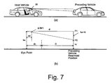
- the eye point height is indicated as "he”
- the distance from the eye point to the display device 81 is indicated as “dd”
- the distance from the eye point to the rearward most portion of the preceding vehicle is indicated as “dl”
- the height of the center of the preceding vehicle is indicated as “hl”.
- the distance “dl” from the eye point to the rearward most portion of the preceding vehicle is set to the value obtained by adding the distance "dc" from the eye point to the front most portion of the vehicle to the following distance D detected by the laser radar 10.
- the preceding vehicle height hl is set to one half of the vehicle height of the preceding vehicle.
- the reference point height ⁇ RP1 on the display device 81 is calculated using the Equation 4 shown below.
- ⁇ RP ⁇ 1 dd ⁇ he - hl / dl
- the system 1 informs the driver that the preceding vehicle can no longer be detected because the preceding vehicle has changed lanes.
- the risk potential marker 82 displayed over the preceding vehicle is turned off in such a fashion that it fades out gradually. Since the preceding vehicle can no longer be detected due to the behavior of the preceding vehicle, the risk potential marker 82 is slowly faded out. In this way, the driver can be informed visually in a reliable manner that the accelerator pedal reaction force will decrease because the preceding vehicle that was targeted by the reaction force control is no longer there.
- the risk potential marker 82 is displayed with a different shape and a notification sound (e.g., a single "ding") is emitted. The notification sound enables the driver to be informed aurally that a preceding vehicle has been detected.
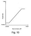
- the controller 50 is configured to change the size of the marker indicating the risk potential RP in accordance with the degree of the risk potential RP. More specifically, the degree of the risk potential marker 82 is controlled such that it increases in accordance with the risk potential RP, i.e., the larger the risk potential RP becomes, the larger the degree of the risk potential marker 82 becomes. As a result, the degree of the risk potential RP can be conveyed to the driver visually in a readily understandable manner.
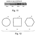
- the controller 50 is configured to change the color of the marker indicating the risk potential RP in accordance with the degree of the risk potential RP. More specifically, the color of the risk potential marker 82 is controlled such that it changes from green to blue to yellow to red in accordance with the degree of the risk potential RP, i.e., as the risk potential RP increases from a small value to a larger value, the color of the risk potential marker 82 changes gradually from green to red, passing through blue and yellow along the way. Since the color of the risk potential marker 82 changes in the manner of a traffic signal installed on a road, the increase in risk potential RP can be recognize intuitively by the driver.
- a vehicle driving assist system in accordance with a second embodiment of the present invention will now be explained.
- the basic constituent features of a vehicle driving assist system in accordance with the second embodiment are the same as those of the first embodiment shown in Figures 1 and 2.
- the second embodiment will be explained chiefly by describing its differences with respect to the first embodiment.
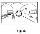
- an image of the obstacle targeted by the calculation of the risk potential RP is generated based on the detection results of the laser radar 10 and the forward camera 20 and the generated image is displayed on the display monitor 81.
- the system 1 is further configured such that plurality of images are generated showing the obstacle from different directions and the driver can select which of the images is displayed.
- the reference value Ds of the following distance D is set to, for example, approximately 20 m.
- the reference size Ms of the marker 82 is set to approximately 3 degrees of viewing angle from the eye point of the driver.
- Figure 26 is a flowchart showing the processing steps of a driving assistance control program executed by the controller 100. This control loop is executed continuously once per prescribed time period, e.g., every 50 msec.
- step S3030 the controller 100 calculates contour lines to be displayed on the display device 81.
- a risk map is created on an imaginary plane as shown in Figure 27. Imaginary points spaced 2 m apart vertically and horizontally are set on the imaginary plane and the risk potential RPx at an imaginary point x is calculated.
- a vehicle driving assist system in accordance with a sixth embodiment of the present invention will now be explained.
- the basic constituent features of a vehicle driving assist system in accordance with the sixth embodiment are the same as those of the fourth embodiment shown in Figure 20.
- the sixth embodiment will be explained chiefly by describing its differences with respect to the fourth embodiment.
- step S5030 the controller 150 checks the obstacles selected in step S5020 as obstacles that could become the targeted obstacle in the future and determines if there is an obstacle among them that is not the obstacle that is currently targeted by the reaction force control.
- the adjacent vehicle shown in diagram (b) of Figure 35 is not the obstacle currently targeted by the actuation reaction force control, but it could possibly become the targeted obstacle in the future. If such another vehicle is detected, the result of step S5030 will be positive and the controller 150 will proceed to step S5090. Meanwhile, if only the currently targeted obstacle is detected, i.e., if there is no other detected obstacle that could possibly become the targeted obstacle in the future, then the controller 150 proceeds to step S5040.
- Figure 36 illustrates an example of how the markers 82 appear on the display device 81.
- Figure 36 illustrates an example in which the system estimates that the driver intends to change lanes into the right-hand adjacent lane while the targeted obstacle A exists in front of the host vehicle and a vehicle that could possibly become the targeted vehicle in the future is detected in the right-hand adjacent lane.
- a circular marker 82A is displayed overlapping the targeted obstacle A.
- a triangular marker 82B is displayed over the obstacle B traveling in the right-hand adjacent lane.
- the marker 82B is displayed in a different color than the marker 82A because both colors are determined in accordance with the risk potentials RP of the corresponding obstacles A and B.
- the marker 82A is illuminated constantly and the marker 82B is flashed on and off to indicate that the obstacle B could possibly become the targeted obstacle in the future.
- the driving force control device 26 executes acceleration control of the vehicle without regard to the accelerator pedal actuation amount SA in order to achieve a set target time to headway THW.
- the controller 250 can execute a plurality of different controls that control the deceleration of the vehicle.
- the controller 250 gives priority to the following cruise control over the RP conveyance control. In other words, when both could be executed, only the following cruise control is executed.
- the controller 250 shifts to a state of executing RP conveyance control only. In short, the following cruise control is overridden by a driving operation executed by the driver.
- step S6110 the controller 250 controls the actuation reaction force exerted by (generated in) the accelerator pedal 72 based on the risk potential RP calculated in step S6020. After the command values are sent, the current control loop ends.
- the system can also be configured such that the brightness of the marker 82 is changed in accordance with the risk potential RP or other value when the marker 82 is displayed on the display device 81.
- the system can also be configured to change either the color or the brightness of the marker 82 in accordance with the risk potential RP or other value.
Landscapes
- Engineering & Computer Science (AREA)
- Mechanical Engineering (AREA)
- Transportation (AREA)
- Chemical & Material Sciences (AREA)
- Combustion & Propulsion (AREA)
- Physics & Mathematics (AREA)
- Automation & Control Theory (AREA)
- Multimedia (AREA)
- General Physics & Mathematics (AREA)
- Human Computer Interaction (AREA)
- Mathematical Physics (AREA)
- Optics & Photonics (AREA)
- Theoretical Computer Science (AREA)
- Radar, Positioning & Navigation (AREA)
- Remote Sensing (AREA)
- Traffic Control Systems (AREA)
- Auxiliary Drives, Propulsion Controls, And Safety Devices (AREA)
- Control Of Driving Devices And Active Controlling Of Vehicle (AREA)
- Regulating Braking Force (AREA)
- Instrument Panels (AREA)
Abstract
Description
- The present invention relates to vehicle driving assist and particularly, but not exclusively, to a system configured to assist a driver with respect to the operation of a host vehicle. More specifically, the present invention relates to a vehicle driving assist system that visually conveys information to the driver about a preceding obstacle that is determined to be a potential risk to the host vehicle. Aspects of the invention also relate to a method and to a vehicle.
- Several conventional vehicle driving assist systems have been proposed for conveying information to a driver of a host about a preceding obstacle that is determined to be a potential risk to the host vehicle. One example of such a vehicle driving assist system is disclosed in
Japanese Laid-Open Patent Publication No. 2004-58919 - A vehicle driving assist system provides information via the sense of touch by controlling an actuation reaction force of a driver-operated device in accordance with a risk potential calculated based on conditions related to obstacles existing in the vicinity of the host vehicle (hereinafter called the "obstacle situation"). However, a vehicle driving assist system that conveys information via the sense of touch alone does not provide the driver with visual information indicating which obstacle is being targeted by the control and how large the risk potential is for that obstacle. Therefore, there exist a need for a system that executes actuation reaction force control based on the risk potential and also conveys visual information to make the state of the actuation reaction force control more readily understandable to the driver.
- It is an aim of the invention to improve upon known technology. Other aims and advantages of the invention will become apparent from the following description, claims and drawings.
- Aspects of the invention therefore provide system, a method and a vehicle as claimed in the appended claims.
- According to another aspect of the invention there is provided a vehicle driving assist system comprising an obstacle detecting section configured to detect a preceding obstacle existing in front of a host vehicle and selectively output an obstacle detection result, a risk potential calculating section configured to calculate a risk potential indicative of a degree of risk potential of the host vehicle with respect to the preceding obstacle based on the obstacle detection result of the obstacle detecting section, a haptic information conveying section configured to convey the risk potential calculated by the risk potential calculating section to a driver as haptic information through a driver-operated driving operation device and a visual information conveying section configured to convey visual information of the preceding obstacle to the driver that is targeted as a targeted obstacle based on the risk potential calculated by the risk potential calculating section.
- In an embodiment, the haptic information conveying section includes an actuation reaction force control section that is configured to control an actuation reaction force exerted by the driver-operated driving operation device based on the risk potential calculated by the risk potential calculating section.
- In an embodiment, the visual information conveying section is configured to convey the degree of the risk potential with respect to the targeted obstacle as calculated by the risk potential calculating section.
- In an embodiment, the visual information conveying section is configured to overlay the targeted obstacle with a risk potential marker indicating the degree of the risk potential as calculated by the risk potential calculating section.
- In an embodiment, the visual information conveying section includes a head up display that is configured to display the risk potential marker in an overlapping manner at a position corresponding to the targeted obstacle on the head up display.
- The system may comprise an imaging section configured to obtain an image of a region in front of the host vehicle. The visual information conveying section may be configured to display the risk potential marker in an overlapping manner at a position corresponding to the targeted obstacle displayed in the image of the region in front of the host vehicle obtained by the imaging section.
- In an embodiment, the visual information conveying section is further configured to display the image of the region in front of the host vehicle and the risk potential marker on a monitor device of a navigation system.
- In an embodiment, the visual information conveying section is further configured to selectively display a targeted obstacle image of the targeted obstacle as viewed from a rear position, from a side position, and from a top position, and display the risk potential marker such that the risk potential marker overlaps the targeted obstacle image of the targeted obstacle.
- In an embodiment, the visual information conveying section is further configured to change a shape of the risk potential marker when the targeted obstacle changes.
- In an embodiment, the visual information conveying section is further configured to change a degree of the risk potential marker in accordance with a change in the degree of the risk potential.
- In an embodiment, the visual information conveying section is further configured to change a color of the risk potential marker in accordance with a change in the degree of the risk potential.
- In an embodiment, the visual information conveying section is further configured to alternately flash the risk potential marker on and off to indicate a change in the degree of the risk potential.
- The system may comprise a relative traveling state determining section configured to determine a relative traveling state of the host vehicle with respect to the targeted obstacle. The visual information conveying section may be arranged to change a brightness of the risk potential marker to indicate the degree of the risk potential based on the relative traveling state determined by the relative traveling state determining section.
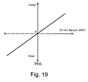
- The system may comprise a convergence degree calculating section configured to calculate a degree of convergence between the host vehicle and the targeted obstacle. The visual information conveying section may be configured to offset a display position of the risk potential marker depending on the degree of convergence calculated by the convergence degree calculating section.
- In an embodiment, the visual information conveying section is further configured to offset the risk potential marker downward relative to the targeted obstacle when the vehicle is approaching the targeted obstacle and offset the risk potential marker upward relative to the targeted obstacle when the vehicle is drawing farther away from the targeted obstacle.
- According to a further aspect of the invention there is provided a vehicle driving assistance method comprising detecting a preceding obstacle existing in front of a host vehicle and selectively outputting an obstacle detection result, calculating a risk potential indicative of a degree of risk potential of the host vehicle with respect to the preceding obstacle based on the obstacle detection result, conveying the risk potential to a driver as haptic information through a driver-operated driving operation device and conveying visual information of the preceding obstacle to the driver that is targeted as a targeted obstacle based on the risk potential.
- According to a still further aspect of the invention there is provided a vehicle driving assist system comprising an obstacle detecting section configured to detect a preceding obstacle existing in front of a host vehicle and selectively output an obstacle detection result, a risk potential calculating section configured to calculate a risk potential indicative of a degree of risk potential of the host vehicle with respect to the preceding obstacle based on the obstacle detection result of the obstacle detecting section, a haptic information conveying section configured to convey the risk potential calculated by the risk potential calculating section to a driver as haptic information through a driver-operated driving operation device and a visual information conveying section configured to convey visual information of the degree of the risk potential to the driver of the preceding obstacle that is targeted as a targeted obstacle by the control executed by the haptic information conveying section.
- In an embodiment, the risk potential calculating section is further configured to calculate the risk potential with respect to each of a plurality of preceding obstacles existing in front of the host vehicle. The visual information conveying section may be further configured to display the degree of the risk potential of the host vehicle with respect to each of the preceding obstacles on a displaying section.
- In an embodiment, the visual information conveying section is further configured to display the degree of the risk potential of the host vehicle with respect to each of the preceding obstacles that has been predicted by the risk potential calculated by the risk potential calculating section as possibly becoming the targeted obstacle at a future time.
- In an embodiment, the visual information conveying section is further configured to display the risk potential of the host vehicle with respect to each of the preceding obstacles for which the risk potential is equal to or larger than a prescribed value.
- In an embodiment, the visual information conveying section is further configured to display contour lines as a risk potential marker indicating the degree of the risk potential with respect to the targeted obstacle.
- In an embodiment, the visual information conveying section is further configured to display a risk potential marker indicating the degree of the risk potential with respect to the targeted obstacle and to change a display format of the risk potential marker when the targeted obstacle changes.
- In an embodiment, the visual information conveying section is further configured to display a risk potential marker indicating the degree of the risk potential with respect to the targeted obstacle and to change a size of the risk potential marker in accordance with an apparent surface area of the targeted obstacle, which changes as a following distance between the host vehicle and the targeted obstacle changes.
- In an embodiment, the visual information conveying section is further configured to display a risk potential marker indicating the degree of the risk potential and to change a size of the risk potential marker in accordance with a following distance between the host vehicle and the targeted obstacle changes.
- The system may comprise a first braking/driving force control section configured to control a braking/driving force exerted against the host vehicle based on the risk potential calculated by the risk potential calculating section, a second braking/driving force control section configured to control the braking/driving force of the host vehicle such that a prescribed following distance is maintained between the vehicle and the targeted obstacle and an override detecting section configured to detect if operation of the second braking/driving force control section is in an overridden state based on a state of a driving operation executed by the driver.
- The visual information conveying section may be further configured to display a risk potential marker indicating the degree of the risk potential and to change a display format of the risk potential marker when the override detecting section detects that the second braking/driving force control section is in the overridden state.
- The system may comprise a braking/driving force control section configured to control a braking/driving force exerted against the host vehicle based on the risk potential calculated by the risk potential calculating section. The visual information conveying section may include a display section that is configured to display a risk potential marker indicating the risk potential with the visual information conveying section being further configured to change a size of the risk potential marker in accordance with a control amount used by the braking/driving force control section to control the braking/driving force exerted against the host vehicle.
- According to yet another aspect of the invention there is provided a vehicle driving assist system comprising obstacle detecting means for detecting a preceding obstacle existing in front of a host vehicle and selectively outputting an obstacle detection result, risk potential calculating means for calculating a risk potential indicative of a degree of risk potential of the host vehicle with respect to the preceding obstacle based on the obstacle detection result, haptic information conveying means for conveying the risk potential calculated by the risk potential calculating section to a driver as haptic information through a driver-operated driving operation device and visual information conveying means for conveying visual information of at least one of the risk potential and the preceding obstacle to the driver that is targeted as a targeted obstacle based on the risk potential calculated by the risk potential calculating section.
- For example, a vehicle driving assist system according to one embodiment basically comprises an obstacle detecting section, a risk potential calculating section, a haptic information conveying section and a visual information conveying section. The obstacle detecting section is configured to detect a preceding obstacle existing in front of a host vehicle and selectively output an obstacle detection result. The risk potential calculating section is configured to calculate a risk potential indicative of a degree of risk potential of the host vehicle with respect to the preceding obstacle based on the obstacle detection result of the obstacle detecting section. The haptic information conveying section is configured to convey the risk potential calculated by the risk potential calculating section to a driver as haptic information through a driver-operated driving operation device. The visual information conveying section is configured to convey visual information of the preceding obstacle to the driver that is targeted as a targeted obstacle based on the risk potential calculated by the risk potential calculating section.
- Within the scope of this application it is envisaged that the various aspects, embodiments and alternatives set out in the preceding paragraphs, in the claims and in the following description may be taken individually or in any combination thereof.
- The present invention will now be described, by way of example only, with reference to the accompanying drawings in which:
- Figure 1 is a system diagram of a vehicle driving assist system in accordance with a first embodiment of the present invention;
- Figure 2 is a diagrammatic view of a vehicle in which the vehicle driving assist system shown in Figure 1 is installed;
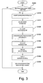
- Figure 3 is a flowchart showing the processing steps executed by a driving assistance control program in accordance with the first embodiment of the present invention;
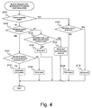
- Figure 4 is a flowchart for explaining the processing steps executed in order to determine the relative traveling state;
- Figure 5 is a series of diagrams illustrating the specific traveling states of Situations B to E;
- Figure 6 is a pair of diagrams illustrating a relationship between the host vehicle and a preceding vehicle in diagram (a), and illustrating in diagram (b) how the region in front of the host vehicle appears through the head up display (HUD) when such a relationship exists;
- Figure 7 illustrates the method of calculating the height of the reference point in accordance with the first embodiment of the present invention, with diagram (a) showing a side elevational view of the host vehicle and a preceding vehicle and diagram (b) showing the calculations for the relationship between the host vehicle and the preceding vehicle in diagram (a);
- Figure 8 illustrates the method of calculating the lateral position of the reference point in accordance with the first embodiment of the present invention, with diagram (a) showing a top plan elevational view of the host vehicle and the preceding vehicle and diagram (b) showing the calculations for the relationship between the host vehicle and the preceding vehicle in diagram (a);
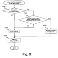
- Figure 9 is a flowchart showing the processing steps executed in order to accomplish the display control in accordance with the first embodiment of the present invention;
- Figure 10 is a graph that plots the reference frame size versus the risk potential in accordance with the first embodiment of the present invention;
- Figure 11 is a bar graph that illustrates the relationship between the risk potential and the color of the reference frame associated with the risk potential in accordance with the first embodiment of the present invention;
- Figure 12 illustrates three examples, diagrams (a) to (c), of reference frame shapes that can be used in accordance with the first embodiment of the present invention;
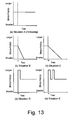
- Figure 13 is a series of graphs, diagrams (a) to (e), that illustrates how the brightness of the reference frame changes with time in each of Situations A to E in accordance with the first embodiment of the present invention;
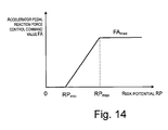
- Figure 14 is a graph that plots the accelerator pedal reaction force control command value versus the risk potential in accordance with the first embodiment of the present invention;
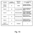
- Figure 15 is a table explaining the operational actions accomplished in Situations A to F in accordance with the first embodiment of the present invention;
- Figure 16 is a diagram of a display that illustrates an example of what is displayed in accordance with a second embodiment of the present invention;
- Figures 17 is a series of displays, diagrams (a) to (c), that illustrates examples of displayed images depicting a preceding vehicle as seen from behind, from a side, and from above in accordance with the second embodiment of the present invention;
- Figure 18 is a diagram of a display that illustrates how the region in front of the host vehicle appears through the head up display (HUD) in accordance with a third embodiment of the present invention;
- Figure 19 is a graph that plots the degree of convergence between the host vehicle and a preceding vehicle versus the reference frame offset amount in accordance with the third embodiment of the present invention;
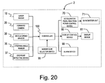
- Figure 20 is a system diagram of a vehicle driving assist system in accordance with a fourth embodiment of the present invention;
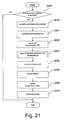
- Figure 21 is a flowchart showing the processing steps executed by a driving assistance control program in accordance with the fourth embodiment of the present invention;
- Figure 22 is a pair of displays, diagrams (a) and (b), illustrating examples of what is displayed in accordance with the fourth embodiment of the present invention;
- Figure 23 is a pair of diagrams (a) and (b) illustrating the concept of the risk potential of the host vehicle in which the driving assist system is installed in accordance with the fourth embodiment of the present invention;
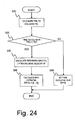
- Figure 24 is a flowchart for explaining the processing steps executed in order to calculate the risk potential in accordance with the fourth embodiment of the present invention;
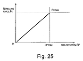
- Figure 25 is a graph that plots the accelerator pedal reaction force control command value versus the risk potential in accordance with the fourth embodiment of the present invention;
- Figure 26 is a flowchart showing the processing steps executed by a driving assistance control program in accordance with a fifth embodiment of the present invention;
- Figure 27 illustrates the method of calculating the risk potential at an imaginary point in accordance with the fifth embodiment of the present invention;
- Figure 28 is a diagram illustrating an example of what is displayed in accordance with the fifth embodiment;
- Figure 29 is a bar graph that illustrates the relationship between the risk potential and the display color of the contour lines associated with the risk potential in accordance with the fifth embodiment of the present invention;
- Figure 30 is a flowchart showing the processing steps executed by a driving assistance control program in accordance with a sixth embodiment of the present invention;
- Figure 31 illustrates three examples, diagrams (a) to (c), of marker shapes that can be used in accordance with the sixth embodiment of the present invention;
- Figure 32 a display illustrating an example of what is displayed in accordance with the sixth embodiment;
- Figure 33 is a system diagram of a vehicle driving assist system in accordance with a seventh embodiment of the present invention;
- Figure 34 is a flowchart showing the processing steps executed by a driving assistance control program in accordance with the seventh embodiment of the present invention;
- Figure 35 is a pair of diagrams (a) and (b) illustrating how the method of selecting an obstacle that could become the targeted obstacle is changed depending on whether or not the driver intends to change lanes in accordance with the seventh embodiment of the present invention;
- Figure 36 illustrates an example of what is displayed in accordance with the seventh embodiment of the present invention;
- Figure 37 is a system diagram of a vehicle driving assist system in accordance with an eighth embodiment of the present invention;
- Figure 38 is a graph that plots the driver's requested driving force versus the accelerator pedal depression amount in accordance with the eighth embodiment of the present invention;
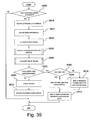
- Figure 39 is a flowchart showing the processing steps executed by a driving assistance control program in accordance with the eighth embodiment of the present invention; and
- Figure 40 a display illustrating an example of what is displayed in the eighth embodiment of the present invention.
- Selected embodiments of the present invention will now be explained with reference to the drawings. It will be apparent to those skilled in the art from this disclosure that the following descriptions of the embodiments of the present invention are provided for illustration only and not for the purpose of limiting the invention as defined by the appended claims and their equivalents.
- Referring initially to Figures 1 and 2, a vehicle driving assist
system 1 is illustrated that is installed on a host vehicle (Figure 2) in accordance with a first embodiment of the present invention. In particular, Figure 1 is a system diagram showing the constituent features of a vehicle driving assistsystem 1 in accordance with a first embodiment of the present invention, while Figure 2 is a diagrammatic view of a vehicle having the host vehicle driving assist system installed therein. The main features of the vehicle driving assistsystem 1 will now be explained. The vehicle driving assistsystem 1 is equipped with alaser radar 10, aforward camera 20, avehicle speed sensor 30, asteering angle sensor 35 for detecting a steering angle of asteering wheel 36, an eyepoint detecting device 37, acontroller 50, a driving force control device 60, an accelerator pedal reactionforce control device 70, aservomotor unit 71 built into a linkage mechanism of anaccelerator pedal 72, adisplay control device 80, adisplay device 81 and analarm device 90. - The
laser radar 10 is a radar device that is preferably mounted to a front grill portion, a bumper portion, or the like of the host vehicle and serves to horizontally scan a region in front of the host vehicle with infrared laser light pulses in order to detect obstacles in front of the vehicle. Thelaser radar 10 then measures the reflected light resulting from the infrared light reflecting off of a plurality of objects located in front of the host vehicle (normally, the rear ends of preceding vehicles). By measuring the time required for the reflected light to arrive, thelaser radar 10 detects a following distance, which is known as a time to headway THW, and relative velocity with respect to a preceding vehicle(s). The detected following distances and relative velocities are sent to thecontroller 50. The region in front of the host vehicle scanned by thelaser radar 10 is, for example, ±6 degrees with respect to the front of the host vehicle and the system detects preceding objects existing within this angular range. - The
forward camera 20 includes, for example, a small CCD camera or CMOS camera mounted on an upper portion of the front windshield serves to capture an image of the circumstances of a region of road in front of the host vehicle and send the image to thecontroller 50. Theforward camera 20 constitutes a forward imaging section or device of thesystem 1. The detection region of theforward camera 20 is a region within ±30 degrees horizontally with respect to the longitudinal centerline of the host vehicle. Theforward camera 20 captures an image of the forward road situation within this detection region - The
vehicle speed sensor 30 detects the speed of the host vehicle in which thesystem 1 is installed by measuring the rotational speed of the wheels or the rotational speed of the output side of the transmission and outputs the detected vehicle speed to thecontroller 50. Thesteering angle sensor 35 is an angle sensor installed in the vicinity of thesteering wheel 36 or the steering column (not shown in figures). Thesteering angle sensor 35 detects the steering angle in terms of the rotation of the steering shaft and sends the detected steering angle to thecontroller 50. - The eye
point detecting device 37 is provided to photograph the face of a seated driver in order to calculate the height from the ground surface to the driver's eyes (hereinafter called "eye point height"). The eyepoint detecting device 37 includes, for example, a small camera, e.g., an infrared camera, installed in the vicinity of thesteering wheel 36. Thecontroller 50 calculates the eye point height of the driver based on a signal from the eyepoint detecting device 37. The eyepoint detecting device 37 can also detect the longitudinal position of the driver's seat, the position of the seatbelt adjuster, and the retraction amount of the seatbelt and use the detected values to estimate the weight and height (physique) of the driver. The eye point height can then be calculated based on the estimated physique of the driver. - The
controller 50 comprises a CPU and a ROM, a RAM, and other components peripheral to the CPU and serves to control the entire vehicle driving assistsystem 1. Thecontroller 50 is configured to recognize the traveling situation of the host vehicle based on the distance information received from thelaser radar 10, the information obtained from theforward camera 20 capturing a region in front of the host vehicle, the host vehicle speed obtained from thevehicle speed sensor 30, the steering angle from steeringangle sensor 35, and the information from the eyepoint detecting device 37. Thus, thecontroller 50 recognizes the obstacle situation in the vicinity of the host vehicle, e.g., recognizes the traveling situation with respect to the obstacles in terms of relative distances and relative velocities of the host vehicle with respect to the preceding obstacles. Thecontroller 50 recognizes the obstacle situation in front of the host vehicle by executing a prescribed image processing with respect to the image captured by theforward camera 20. Based on these traveling circumstances (the obstacle situation), thecontroller 50 calculates a risk potential that is a physical quantity indicating the degree of convergence between the host vehicle and the preceding obstacle (or "risk potentials" when there are two or more obstacles). - Based on the risk potential(s) with respect to the preceding obstacle(s), the
controller 50 controls an actuation reaction force exerted by a driver-operated driving operation device operated by the driver in order to drive the host vehicle. In this embodiment, the driver-operated driving operation device is theaccelerator pedal 72. Additionally, the status of the actuation reaction force control executed based on the risk potential is conveyed to the driver as visual information and display control is executed so as to encourage the driver to adjust his or her operation of the driving operation device (e.g., the accelerator pedal 72) in an appropriate direction. The control executed by thecontroller 50 will now be described in detail. - Based on a command from the
controller 50, the accelerator pedal reactionforce control device 70 controls the torque generated by theservomotor unit 71 built into a linkage mechanism of theaccelerator pedal 72. Theservomotor unit 71 controls the reaction force generated based on a command value from the accelerator pedal reactionforce control device 70 and can freely control the actuation reaction force (depression force) generated when the driver operates theaccelerator pedal 72. The normal reaction force characteristic that exists when actuation reaction force control is not being executed is, for example, the spring force of a coil spring and is set such that the actuation reaction force increases proportionally to the increase in the depression amount of theaccelerator pedal 72. - In response to a command from the
controller 50, thedisplay control device 80 generates an image to be displayed on thedisplay device 81. Thedisplay device 81 is preferably a head up display (HUD) that is configured to use the entire front windshield as an image projection surface. Thedisplay device 81 displays the image in accordance with a signal from thedisplay control device 80 and is designed to convey information regarding the risk potential, etc., to the driver while the driver is looking forward. Since the obstacle targeted by the risk potential calculation can be conveyed as visual information in addition to conveying the risk potential as haptic information, the driver can be informed visually regarding which obstacle is being targeted by the haptic information conveyed via the driver-operated driving operation device. - The
alarm device 90 equipped with a speaker is configured to emit an alarm sound or other audio information in response to a command from thecontroller 50 in order to alert, notify and/or inform the driver of a risk potential of a preceding obstacle. - The operation of the vehicle driving assist
system 1 in accordance with the first embodiment of the present invention will now be explained in more detail with reference to Figure 3. Figure 3 is a flowchart showing the processing steps of a driving assistance control program executed by thecontroller 50. This control loop is executed continuously once per prescribed time period, e.g., every 50 msec. - In step S1000, the
controller 50 determines if actuation reaction force control is currently being executed based on the risk potential. More specifically, thecontroller 50 determines if thelaser radar 10 has detected an obstacle in front of the host vehicle, making it possible to execute actuation reaction force control based on the risk potential RP. If the result of step S1000 is positive, then thecontroller 50 proceeds to step S1010. If the result of step S1000 is negative, then thecontroller 50 ends the control loop. - In step S1010, the
controller 50 reads traveling or surrounding information regarding the surroundings of the host vehicle. The surrounding information mentioned here constitutes information related to the traveling circumstances of the host vehicle, including information regarding obstacles in front of the host vehicle. Thus, thecontroller 50 reads in the following distance D between the host vehicle and the preceding obstacle detected by thelaser radar 10, the relative velocity Vr with respect to the preceding obstacle, and the existence direction θ1 from the host vehicle to the preceding obstacle. Thecontroller 50 also reads the traveling speed V of the host vehicle detected by thevehicle speed sensor 30 and the steering angle S detected by thesteering angle sensor 35. - In step S1011, the
controller 50 acquires driver information. More specifically, thecontroller 50 calculates an eye point height "he" of the driver based on a signal from the eyepoint detecting device 37. Thecontroller 50 also calculates the longitudinal distance "dc" from the front end (front most portion) of the host vehicle to the driver's eyes ("eye point") and the longitudinal distance "dd" from thedisplay device 81 to the eye point based on the seat position of the driver's seat. The longitudinal distances "dc" and "dd" can also be set to prescribed values in advance. - In step S1020, the
controller 50 calculates the risk potential RP of the host vehicle with respect to the preceding obstacle. In step S1020, thecontroller 50 first calculates the time to collision TTC and the time to headway THW between the vehicle and the preceding obstacle. - The time to collision TTC is a physical quantity indicating the current degree of convergence of the host vehicle with respect to the preceding obstacle, which is, for example, a preceding vehicle. The time to collision TTC is a value that indicates how many seconds before the following distance D becomes zero and the host vehicle and the preceding vehicle contact each other assuming that the current traveling circumstances continue, i.e., assuming that the vehicle speed V, the preceding vehicle speed Vf, and the relative vehicle speed Vr remain constant. The relative velocity Vr equals the vehicle speed V minus the preceding vehicle speed Vf (Vr = V - Vf). The time to collision TTC is found using the
Equation 1 shown below.
- The smaller the time to collision TTC is, the more eminent the contact with the preceding vehicle is and the larger the degree of convergence with respect to the preceding vehicle is. For example, it is known that when approaching a preceding vehicle, most drivers start taking action to decelerate before the time to collision TTC reaches 4 seconds or less.
- The time to headway THW is a physical quantity that is relevant when the vehicle is following a preceding vehicle and indicates the degree of influence changes in the speed of the preceding vehicle (which are assumed to occur in the future) will have on the time to collision TTC, i.e., the degree of influence under the assumption that the relative velocity Vr will change. The time to headway THW is found using the
Equation 2 shown below.
- The time to headway THW equals the following distance D divided by the vehicle speed V and thus indicates the amount of time required for the vehicle to move from its current position to the current position of the preceding vehicle. The larger the time to headway THW is, the smaller is the amount of influence that the surroundings have on the degree of convergence. In other words, when the time to headway THW is large, any future change in the speed of the preceding vehicle will not have a large effect on the degree of convergence between the host vehicle and the preceding vehicle and, thus, the time to collision TTC will not change very much. When the vehicle is following a preceding vehicle and the vehicle speed V equals the preceding vehicle speed Vf, then the preceding vehicle speed Vf can be used in
Equation 2 instead of the vehicle speed V to calculate the time to headway THW. - The risk potential RP is calculated with the
Equation 3 below using the time to collision TTC and time to headway THW.
- In the equation, A and B are constants serving to appropriately weight the inverse of the time to headway THW and the inverse of the time to collision TTC. The constants A and B are set in advance to appropriate values, e.g., A =1 and B = 8 (A < B).
- The term "risk potential" refers to the degree of risk or possibility of danger. In this embodiment, the risk potential is contrived to increase as the host vehicle and an obstacle existing in the vicinity of the vehicle draw closer together. Thus, it can be said that the risk potential is a physical quantity that expresses how close the host vehicle and the obstacle are to each other, i.e., the degree to which the host vehicle and the preceding obstacle have drawn near to each other (degree of convergence).
- In step S1030, the
controller 50 calculates the relative traveling state of the host vehicle with respect to the preceding obstacle. The control processing executed in order to accomplish step S1030 will now be explained with reference to the flowchart of Figure 4. - In step S1100, the
controller 50 estimates if the host vehicle is changing lanes based on the steering angle S read in step S1010. For example, it can be determined that the host vehicle is changing lanes when the detected steering angle S is larger than a standard range of steering angles beyond which the host vehicle generally does not depart when it is staying in the same lane. It is also possible to determine if the host vehicle is changing lanes based on the operation of a turn signal by the driver or an estimate of whether the driver intends to change lanes (obtained using any of various methods exist). - If it determines in step S1100 that the host vehicle is not changing lanes, then the
controller 50 proceeds to step S1105 and determines if thelaser radar 10 or theforward camera 20 detects an obstacle, e.g., a preceding vehicle, in front of the host vehicle. If a preceding vehicle is being detected, then thecontroller 50 proceeds to step S1110 and determines if a preceding vehicle was also detected in the previous control cycle. If the preceding vehicle was detected in the previous control cycle, then the controller proceeds to stepS 1115 and determines that the host vehicle is following a preceding vehicle ("Situation A"). - If it determines in step S1100 that the vehicle is changing lanes, then the
controller 50 proceeds to step S 1120 and determines if a preceding vehicle is being detected. If a preceding vehicle is not detected, then thecontroller 50 proceeds to step S 1125. In step S 1125, thecontroller 50 determines that the preceding vehicle can no longer be detected because the host vehicle has changed lanes, as shown in diagram (a) of Figure 5. This relative traveling state is called "Situation B." Meanwhile, if it determines in step S 1120 that a preceding vehicle is detected, then thecontroller 50 proceeds to step S1130. In step S1130, the controller determines that a preceding vehicle came to be detected as a result of the host vehicle changing lanes, as shown in diagram (c) of Figure 5. This relative traveling state is called "Situation D." - If it determines in step S 1105 that a preceding vehicle is not detected, then the
controller 50 proceeds to step S1132 and determines if a preceding vehicle was also not detected in the previous control cycle. If a preceding vehicle was detected in the preceding cycle, then thecontroller 50 proceeds to step S1135. In step S1135, thecontroller 50 determines that the preceding vehicle can no longer be detected because the preceding vehicle has changed lanes, as shown in diagram (c) of Figure 5. This relative traveling state is called "Situation C." Meanwhile, if it determines in step S 1132 that a preceding vehicle was not detected in the previous cycle, then thecontroller 50 proceeds to step S 1137 and determines that a preceding vehicle has not been detected ("Situation F"). - If it determines in step S1110 that a preceding vehicle was not detected in the previous control cycle, then the
controller 50 proceeds to step S1140. In step S1140, thecontroller 50 determines that a preceding vehicle came to be detected because the preceding vehicle changed into the same lane as the vehicle, as shown in diagram (d) of Figure 5. This relative traveling state is called "Situation E." Situation E includes cases in which the host vehicle approaches a preceding vehicle that was previously too far away to be detected (i.e., the preceding vehicle starts being detected not because of a lane change but because the host vehicle drew close enough to detect the preceding vehicle for the first time). - After the
controller 50 determines the relative traveling state between the host vehicle and the preceding vehicle in step S1030, then thecontroller 50 proceeds to step S1400. In step S1040, thecontroller 50 calculates a reference point of the image displayed on thedisplay device 81. Diagram (a) of Figure 6 depicts a relationship between the host vehicle and the preceding vehicle, while diagram (b) of Figure 6 illustrates an image of what is seen when the preceding vehicle is viewed through thedisplay device 81 when such a relationship exists. - In diagram (b) of Figure 6, the eye point of the driver is indicated as "P1" and corresponds to a position aligned with the line of sight of the driver. The center position of the rearward most tail portion of the preceding vehicle is indicated as "P2." In this embodiment, the center position P2 of the rearward most tail portion is taken as the reference point. The eye point position P1 is set based on a driver center and the eye point height "he". A round reference frame or risk
potential marker 82 is displayed on thedisplay device 81 so as to be centered on the reference point P2. The reference frame or 82 indicates the obstacle targeted by the calculation of the risk potential RP and is displayed in such a position as to overlap the preceding vehicle when viewed by the driver. Atime counter 83 is also displayed on thedisplay device 81 and will be discussed later. - The reference position P2 is expressed in terms of a relative height (reference point height) ΔRP1 and relative lateral position (reference point lateral position) ΔRP2 with respect to the eye point position P1 on the
display device 81. The method of calculating the reference point height ΔRP1 will now be explained. Diagram (a) of Figure 7 illustrates the relationship between the host vehicle and the preceding vehicle and diagram (b) of Figure 7 depicts the concept of the calculation of the referencepoint height ΔRP 1. - In diagram (b) of Figure 7, the eye point height is indicated as "he", the distance from the eye point to the
display device 81 is indicated as "dd", the distance from the eye point to the rearward most portion of the preceding vehicle is indicated as "dl", and the height of the center of the preceding vehicle is indicated as "hl". The distance "dl" from the eye point to the rearward most portion of the preceding vehicle is set to the value obtained by adding the distance "dc" from the eye point to the front most portion of the vehicle to the following distance D detected by thelaser radar 10. The preceding vehicle height hl is set to one half of the vehicle height of the preceding vehicle. The reference point height ΔRP1 on thedisplay device 81 is calculated using theEquation 4 shown below.
- Next, the method of calculating the reference point lateral position ΔRP2 will be explained. In Figure 8, diagram (a) illustrates the relationship between the host vehicle and the preceding vehicle, while diagram (b) depicts the concept of the calculation of the reference point lateral position ΔRP2. In diagram (b) of Figure 8, the existence direction (angle) of the preceding vehicle from the vehicle detected by the
laser radar 10 is indicated as "θ1" and the distance from the longitudinal center line of the host vehicle (vehicle center) to the eye point of the driver (driver center) is indicated as "lc." The longitudinal distance from the eye point to the rearward most portion of the preceding vehicle is expressed as dc + d × cos θ1 and the distance from the eye point to the lateral center position of the preceding vehicle is expressed as d × sin θ1 - 1c. The reference point lateral position ΔRP2 on thedisplay device 81 is calculated using the Equation 5 shown below.
- In step S1050, the
controller 50 executes display control of thedisplay device 81 based on the relative traveling state of the host vehicle with respect to the preceding vehicle determined in step S1030 and the reference point calculated in step S1040. The control processing executed in order to accomplish step S1050 will now be explained with reference to the flowchart of Figure 9. - In step S1052, the
controller 50 determines if the traveling situation determined in step S1030 was Situation A (following). If Situation A was determined, then thecontroller 50 proceeds to step S1053 and determines if the following state with respect to the preceding vehicle is stable. More specifically, thecontroller 50 determines if the time to headway THW calculated in step S1020 has been within a prescribed range in a continuous fashion. For example, thecontroller 50 might determine that the following state is stable if the time to headway THW has been within 2 ±0.25 seconds continuously for 5 seconds or more. If so, thecontroller 50 proceeds to step S1054. In step S1054, thecontroller 50 counts the amount of time the time to headway THW has satisfied the condition of being within the prescribed range continuously for at least the prescribed amount of time, i.e., the amount of time elapsed since the result of step S1053 first became positive (i.e., the amount of time the following situation has continued, hereinafter called "headway situation time"). - If either step S1052 or step S1053 is negative, then the
controller 50 proceeds to step S1055 and resets the headway situation time counter. - In step S1056, the
controller 50 determines a display format with which to display an image on thedisplay device 81 based on the risk potential RP, the relative traveling state with respect to the preceding vehicle, the reference point position, etc., and executes display control processing. The riskpotential marker 82 is displayed centered on the reference point P2 calculated in step S1040 so as to indicate the obstacle targeted by the calculation of the risk potential RP, i.e., targeted by the reaction force control. The degree of the riskpotential marker 82 is set such that it increases as the risk potential RP increases, as indicated in Figure 10. When the risk potential RP is equal to or above a prescribed value, e.g., 2, the riskpotential marker 82 is displayed in a flashing fashion so as to alert the driver. - In addition to the degree of the risk
potential marker 82, the color of the riskpotential marker 82 is also changed in accordance with the risk potential RP. More specifically, as shown in Figure 11, the color of the riskpotential marker 82 is varied gradually from green to blue, from blue to yellow, and from yellow to red as the risk potential RP increases. Although in this embodiment the color of the riskpotential marker 82 is changed gradually from green to red, it is also possible to establish a plurality of predetermined ranges of risk potential RP values and assign a specific color to each range. - Several shapes are set in advance for the risk
potential marker 82, e.g., a circular shape like that shown in diagram (a) of Figure 12, a square shape like that shown in diagram (b) of Figure 12, and a polygonal shape like that shown in diagram (c) of Figure 12. Other shapes of riskpotential marker 82 can also be set. The shape of the riskpotential marker 82 is changed each time the preceding vehicle is replaced with a difference preceding vehicle. The line thickness of the riskpotential marker 82 is set to such a thickness that the visibility in the frontward direction is not inhibited when the riskpotential marker 82 is displayed on thedisplay device 81 in such a manner that it overlaps the preceding vehicle. - The brightness of the risk
potential marker 82 is set in accordance with the relative traveling state between the host vehicle and the preceding vehicle. Diagrams (a) to (e) of Figure 13 illustrate how the brightness of the riskpotential marker 82 changes with time in each of Situations A to E. When Situation A exists, i.e., when the host vehicle is following a preceding vehicle, the brightness of the riskpotential marker 82 remains constant as shown in diagram (a) of Figure 13. When Situation B occurs, the brightness is gradually decreased to zero starting from the time t1 when it is determined that Situation B exists, as shown in diagram (b) of Figure 13. When Situation C occurs, the brightness is gradually decreased to zero starting from the time t2 when it is determined that Situation C exists, as shown in diagram (c) of Figure 13. The rate at which the brightness changes is slower than in the case of Situation B. - When Situation D occurs, the brightness of the risk
potential marker 82 is suddenly raised to the maximum brightness in a pulse-like manner at the time t3 when it is determined that Situation D exists, as shown in diagram (d) of Figure 13. After the riskpotential marker 82 is displayed at the maximum brightness for a moment, the brightness is dropped to a prescribed value and held constant. When Situation E occurs, the riskpotential marker 82 is displayed at maximum brightness at the time t4 when it is determined that Situation E exists. The brightness is then dropped temporarily and raised to the maximum value again. After the riskpotential marker 82 is displayed at the maximum brightness twice in a pulse-like fashion, the brightness is dropped to a prescribed value and held constant. The maximum brightness at which the riskpotential marker 82 is displayed when the brightness is raised in a pulse like manner is set to an appropriate value such that the riskpotential marker 82 does not inhibit the driver's ability to operate the vehicle. - In this way, the
controller 50 determines the display format of the riskpotential marker 82 and sends a signal to thedisplay control device 80 such that the riskpotential marker 82 is displayed on thedisplay device 81 at the set size, color, and brightness. When the headway situation time is being counted because it has been determined that Situation A exists, i.e., that the vehicle is following a preceding vehicle, atime counter 83 indicating the headway situation time is displayed in addition to the riskpotential marker 82, as shown in diagram (b) of Figure 6. It is preferable for thetime counter 83 to be displayed at the bottom of thedisplay device 81 so as not to impede the driver's visibility in the frontward direction. When the headway situation time is not being counted, a random numerical value is displayed or thetime counter 83 is turned off (not displayed). - In step S1060, the
controller 50 sends a command to thealarm device 90 instructing it to emit an alarm sound. More specifically, if a preceding vehicle has been newly detected by thelaser radar 10 or theforward camera 20, such as in the case of Situation D or Situation E, a notification sound (e.g., a single "ding") is emitted to inform the driver that the system has begun detecting a preceding vehicle. When the risk potential RP exceeds a prescribed value, e.g., 2, an alarm sound (e.g., a "beep-beep" sound) is emitted so as to alert the driver. - In step S1070, the
controller 50 controls the actuation reaction force exerted by (generated in) theaccelerator pedal 72 based on the risk potential RP calculated in step S1020. Using the map shown in Figure 14, thecontroller 50 calculates an accelerator pedal reaction force control command value FA in accordance with the risk potential RP. As shown in Figure 14, the accelerator pedal reaction force control command value FA is set such that it increases as the risk potential RP increases once the risk potential RP exceeds a prescribed value RPmin. When risk potential RP exceeds another prescribed value RPmax, the reaction force control command value FA is held constant at a maximum value FAmax. - The
controller 50 outputs the calculated accelerator pedal reaction force control command value FA to the accelerator pedal reactionforce control device 70. The accelerator pedal reactionforce control device 70 controls the actuation reaction force exerted by theaccelerator pedal 72 based on the command value received from thecontroller 50. More specifically, the accelerator pedal reactionforce control device 70 causes theaccelerator pedal 72 to exert a reaction force equal to the value obtained by adding the reaction force control command value FA to the normal reaction force, which is determined based on a characteristic that expresses the reaction force versus the accelerator pedal actuation amount SA. After the command values are sent, the current control loop ends. - The operational action achieved with a vehicle driving assist
system 1 in accordance with the first embodiment of the present invention will now be explained. Figure 15 summarizes the operational actions executed by thesystem 1 in the case of each of Situations A to F. In the case of Situation A, the vehicle is not changing lanes and is simply following the preceding vehicle. Consequently, thesystem 1 leads the driver to operate the accelerator pedal such that the vehicle follows the preceding vehicle while maintaining an appropriate following distance. On thedisplay device 81, the riskpotential marker 82 is displayed at a constant brightness in a position overlapping the obstacle that is targeted by the reaction force control and thetime counter 83 indicates the amount of time elapsed since the vehicle entered a stable following state. The time counter 83 functions as an indicator informing the driver that the stable following state is continuing. - In the case of Situation B, the
system 1 informs the driver that the preceding vehicle can no longer be detected because the vehicle has changed lanes. The riskpotential marker 82 displayed over the preceding vehicle is turned off in such a fashion that it fades out gradually. In this way, the driver can be informed visually in a reliable manner that the accelerator pedal reaction force will decrease because the preceding vehicle that was targeted by the reaction force control is no longer there. - In the case of Situation C, the
system 1 informs the driver that the preceding vehicle can no longer be detected because the preceding vehicle has changed lanes. Here, too, the riskpotential marker 82 displayed over the preceding vehicle is turned off in such a fashion that it fades out gradually. Since the preceding vehicle can no longer be detected due to the behavior of the preceding vehicle, the riskpotential marker 82 is slowly faded out. In this way, the driver can be informed visually in a reliable manner that the accelerator pedal reaction force will decrease because the preceding vehicle that was targeted by the reaction force control is no longer there. If another preceding vehicle is detected after the first preceding vehicle stops being detected, the riskpotential marker 82 is displayed with a different shape and a notification sound (e.g., a single "ding") is emitted. The notification sound enables the driver to be informed aurally that a preceding vehicle has been detected. - In the case of Situation D, the
system 1 informs the driver that a preceding vehicle has come to be detected as a result of the vehicle changing lanes. After the riskpotential marker 82 is displayed brightly for a moment (i.e., in a pulse-like manner), it is displayed overlapping the preceding vehicle, which is targeted by a new execution of the reaction force control. A notification sound ("ding") is also emitted. As a result, the driver can be notified in a clear manner which obstacle is the obstacle with respect to which the risk potential RP is being calculated and the reaction force is being executed. Since the size and color of the riskpotential marker 82 change in accordance with the risk potential RP, the driver can check the actuation reaction force exerted by theaccelerator pedal 72 visually (i.e., the reaction force can be conveyed with visual information). - In the case of Situation E, the
system 1 informs the driver that a new targeted preceding vehicle has been detected as a result of the preceding vehicle changing lanes or that a new preceding vehicle has begun being detected. Since the preceding vehicle comes to be detected regardless of the operation of the vehicle, the riskpotential marker 82 is flashed brightly in two pulses to ensure in a reliable manner that the driver recognizes that the preceding vehicle has been detected. Then, the riskpotential marker 82 is displayed overlapping the preceding vehicle, which is targeted by a new execution of the reaction force control. A notification sound ("ding") is also emitted. As a result, the driver can be notified in a clear manner which obstacle is the obstacle with respect to which the risk potential RP is being calculated and the reaction force is being executed. Since the size and color of the riskpotential marker 82 change in accordance with the risk potential RP, the driver can check the actuation reaction force exerted by theaccelerator pedal 72 visually (i.e., the reaction force can be conveyed with visual information). - In the case of Situation F, accelerator pedal reaction force control and display control are not executed because a preceding vehicle does not exist.
- The first embodiment described heretofore can thus provide the following operational effects.
- The vehicle driving assist
system 1 is configured to detect an obstacle existing in front of the host vehicle in which thesystem 1 is installed and calculate a risk potential RP of the vehicle with respect to the obstacle based on the obstacle detection results. Thesystem 1 conveys the calculated risk potential RP to the driver as haptic information through a driver-operated device used by the driver in order to operate the vehicle and also conveys the risk potential RP as visual information. More specifically, thesystem 1 conveys the obstacle that is targeted by the calculation of the risk potential RP (targeted obstacle) to the driver as visual information. Since the risk potential RP is transmitted to the driver both as haptic information and as visual information, the status of the conveyance of the haptic information through the driver-operated device can be checked visually be the driver, thereby assisting the driver in grasping the haptic information and making the control more readily understandable. By conveying the targeted obstacle visually (as visual information), the driver can be made aware of which obstacle is targeted by the actuation reaction force exerted by the driver-operated device. - The vehicle driving assist
system 1 is configured to convey the haptic information by controlling the actuation reaction force exerted by the driver-operated driving operation device based on the risk potential RP. Since the risk potential RP is communicated to the driver through the actuation reaction force exerted by a driver-operated device that the driver contacts frequently in order to drive the vehicle, the risk potential RP can be communicated to the driver continuously in an intuitive manner. - The vehicle driving assist
system 1 is configured to convey the degree of the risk potential RP with respect to the targeted obstacle using visual information. As a result, the degree of the risk potential RP of the vehicle can be conveyed to the driver visually in addition to being conveyed through the size of the actuation reaction force. - The vehicle driving assist
system 1 is configured to overlay the targeted obstacle with a marker indicating the risk potential RP. As a result, which obstacle is the targeted obstacle can be communicated to the driver in a readily understandable manner. - The vehicle driving assist
system 1 is equipped with the head up display (HUD) 81 and configured to display the riskpotential marker 82 indicating the risk potential RP on thedisplay device 81 in an overlapping manner at a position corresponding to the targeted obstacle. For example, as shown in diagram (b) of Figure 6, the riskpotential marker 82 is displayed at the position on thedisplay device 81 corresponding to the preceding vehicle such that the riskpotential marker 82 appears to overlap the preceding vehicle from the driver's point of view. In this example, the riskpotential marker 82 is the marker indicating the risk potential RP. As a result, the driver can immediately and accurately recognize which obstacle is targeted by the calculation of the risk potential RP and the control of the actuation reaction force while looking forward and driving the vehicle. - The
controller 50 is configured to change the shape of the marker indicating the risk potential RP when the targeted obstacle changes. For example, circular, square, and polygonal riskpotential markers 82 like those shown in diagrams (a) to (c) of Figures 12 can be prepared and the riskpotential marker 82 of a different shape can be displayed each time the preceding vehicle changes due to a lane change or a preceding vehicle is newly detected. As a result, the driver can be readily recognize the change when the targeted obstacle changes. - The
controller 50 is configured to change the size of the marker indicating the risk potential RP in accordance with the degree of the risk potential RP. More specifically, the degree of the riskpotential marker 82 is controlled such that it increases in accordance with the risk potential RP, i.e., the larger the risk potential RP becomes, the larger the degree of the riskpotential marker 82 becomes. As a result, the degree of the risk potential RP can be conveyed to the driver visually in a readily understandable manner. - The
controller 50 is configured to change the color of the marker indicating the risk potential RP in accordance with the degree of the risk potential RP. More specifically, the color of the riskpotential marker 82 is controlled such that it changes from green to blue to yellow to red in accordance with the degree of the risk potential RP, i.e., as the risk potential RP increases from a small value to a larger value, the color of the riskpotential marker 82 changes gradually from green to red, passing through blue and yellow along the way. Since the color of the riskpotential marker 82 changes in the manner of a traffic signal installed on a road, the increase in risk potential RP can be recognize intuitively by the driver. - The
controller 50 is configured to flash the marker indicating the risk potential RP on and off depending on the degree of the risk potential RP. More specifically, when the risk potential RP is high (e.g., RP ≥ 2) and the possibility that the vehicle will contact the preceding vehicle is high, the riskpotential marker 82 is flashed in order to alert the driver and urge caution. - The
controller 50 is configured to identify the relative traveling state existing between the vehicle and the targeted obstacle and change the brightness of the marker indicating the risk potential RP in accordance with the relative traveling state. More specifically, as shown in Figure 15, the relative traveling states that can exist between the vehicle and a preceding vehicle are categorized into six situations and the brightness of the riskpotential marker 82 is changed as shown in diagrams (a) to (e) of Figure 13 depending on which situation exists. When Situation B or C exists and the preceding vehicle will stop being detected, the brightness is gradually decreased such that the riskpotential marker 82 fades out. In this way, the driver can be informed visually that the risk potential RP that exists with respect to the current preceding vehicle will soon disappear in the future. When Situation D or E exists and a preceding vehicle will start being detected, the riskpotential marker 82 is illuminated at the highest brightness momentarily in a pulse-like manner. In this way, driver can be informed visually that actuation reaction force control will be started with respect to a new obstacle. - A vehicle driving assist system in accordance with a second embodiment of the present invention will now be explained. The basic constituent features of a vehicle driving assist system in accordance with the second embodiment are the same as those of the first embodiment shown in Figures 1 and 2. The second embodiment will be explained chiefly by describing its differences with respect to the first embodiment.
- A vehicle driving assist system in accordance with the second embodiment uses the display monitor of a navigation system as the
display device 81 instead of an HUD. When actuation reaction force control in accordance with the risk potential RP starts, an image of a region in front of the host vehicle captured by theforward camera 20 is displayed on thedisplay monitor 81. Additionally, a riskpotential marker 82 is displayed overlapping the preceding obstacle that is targeted by the calculation of the risk potential RP. Figure 16 illustrates an example of the image displayed on thedisplay monitor 81. - The display format of the image displayed on the display monitor 81 is determined in the same manner as in the first embodiment except that the size and position of the risk
potential marker 82 are adjusted to the screen of thedisplay monitor 81. The riskpotential marker 82 can also be displayed using a method other than that explained in the first embodiment. For example, the display position can be determined and the overlapping display can be accomplished by applying a pattern recognition processing or other image processing to the image captured with theforward camera 20. More specifically, a preceding vehicle existing in the same lane as the vehicle can be recognized using pattern recognition and the reference point P2 can be set to the center position of the recognized preceding vehicle on thedisplay monitor 81. - Furthermore, instead of the display monitor of a navigation system, it is also possible to use an LCD monitor installed inside the instrument cluster of the dashboard as the
display device 81. - In addition to the operational effects exhibited by the first embodiment, the second embodiment also achieves the following additional effects.
- The vehicle driving assist
system 1 is equipped with aforward camera 20 configured and arranged to photograph a region in front of the host vehicle. A marker indicating the risk potential RP is displayed in a position corresponding to the targeted obstacle on the image captured by the front camera such that the marker overlaps the image of the targeted obstacle. For example, as shown in Figure 16, the riskpotential marker 82 is displayed so as to overlap a preceding vehicle existing in front of the host vehicle in the same lane. Although the image captured by theforward camera 20 in Figure 16 includes a plurality of obstacles, the riskpotential marker 82 enables the driver to readily recognize which obstacle is targeted by the calculation of the risk potential RP and the execution of the actuation reaction control. - The vehicle driving assist
system 1 is configured to display an image of the region in front of the host vehicle and the marker indicating the risk potential on amonitor device 81 of a navigation system. Since themonitor device 81 of a navigation system is used as the display device, the cost of thissystem 1 can be curbed because it is not necessary to provide a separate display device. - In this variation, instead of displaying the image captured by the
forward camera 20, an image of the obstacle targeted by the calculation of the risk potential RP is generated based on the detection results of thelaser radar 10 and theforward camera 20 and the generated image is displayed on thedisplay monitor 81. Thesystem 1 is further configured such that plurality of images are generated showing the obstacle from different directions and the driver can select which of the images is displayed. - Diagrams (a) to (c) of Figure 17 illustrate examples of generated images. A risk
potential marker 82 indicating the target of the calculation of the risk potential RP is displayed in an overlapping manner over theimage 84 of a preceding vehicle. The size, color, and shape of the riskpotential marker 82 are determined in the same manner as described regarding the first embodiment. Diagram (a) of Figure 17 is an example of a generated image showing the preceding vehicle from the rear. This image illustrates the precedingvehicle 84 as it would actually look when viewed by the driver from inside the vehicle and also includes the riskpotential marker 82 andlane markers 85 demarcating the lane in which the vehicle is traveling. - Diagram (b) of Figure 17 is an example of a generated image showing the preceding vehicle from a side. In this image, the displayed size of the preceding
vehicle image 84 is changed in accordance with the relative traveling state between the host vehicle and the preceding vehicle. More specifically, the displayed size of the precedingvehicle image 84 is reduced when Situation B or C exists and the preceding vehicle will no longer be detected because the preceding vehicle is changing lanes or the like. Meanwhile, the displayed size of the precedingvehicle image 84 is enlarged when Situation D or E exists and a preceding vehicle will start being detected because the preceding vehicle is changing lanes or the like. Also, anindicator 86 is also displayed in a position located behind the precedingvehicle 84 in the image on the screen. Theindicator 86 indicates the following distance D between the host vehicle and the preceding vehicle and the degree of the risk potential RP. - Diagram (c) of Figure 17 is an example of a generated image showing the preceding vehicle from above. In this image, as indicated with the arrows, the lateral position of the displayed preceding
vehicle 84 is changed in accordance with the relative traveling state between the host vehicle and the preceding vehicle. For example, if the vehicle changes lanes in the rightward direction, the precedingvehicle image 84 will shift leftward on the display screen. Similarly, if the vehicle changes lanes in the leftward direction, the precedingvehicle image 84 will shift rightward on the display screen. Also, anindicator 86 is also displayed in a position located behind the precedingvehicle 84 in the image on the screen. Theindicator 86 indicates the following distance D between the host vehicle and the preceding vehicle and the degree of the risk potential RP. - The driver can change the displayed image by, for example, operating a joystick (not shown) provided in the vicinity of the
display monitor 81. It is also possible to configure the system such that the driver can change the displayed image using a toggle key or button provided on the navigation system. Instead of the display monitor of a navigation system, it is also possible to use an LCD monitor installed inside the instrument cluster of the dashboard as thedisplay device 81. - Thus, the
controller 50 is configured to generate at least an image that illustrates the targeted object as viewed from the rear, from a side, or from above and display a marker indicating the risk potential in such a manner that the marker overlaps the generated image of the targeted obstacle. As a result, the relationship between the vehicle and the targeted obstacle can be displayed from a variety of angles. - A vehicle driving assist system in accordance with a third embodiment of the present invention will now be explained. The basic constituent features of a vehicle driving assist system in accordance with the third embodiment are the same as those of the first embodiment shown in Figures 1 and 2. The third embodiment will be explained chiefly by describing its differences with respect to the first embodiment.
- In the third embodiment, the display position of the risk
potential marker 82 displayed on thedisplay device 81 is changed in accordance with the degree of convergence between the host vehicle and the preceding vehicle. More specifically, when the host vehicle draws closer to the preceding vehicle, position of the riskpotential marker 82 is lowered so as to approach the vehicle in a virtual (imaginary) manner. Meanwhile, when the host vehicle draws farther away from the preceding vehicle, the position of the riskpotential marker 82 is raised so as to move away from the host vehicle in a virtual (imaginary) manner. Figure 18 is an image of what is seen when the preceding vehicle is viewed through thedisplay device 81 in a case in which the vehicle is drawing close to the preceding vehicle. The position of the riskpotential marker 82 has been shifted downward from the reference point P2 by an offset amount ΔRP1' in accordance with the degree of convergence. - Figure 19 is a plot of the inverse TTCi of the time to collision TTC versus the offset amount ΔRP1'. The closer the host vehicle and the preceding vehicle draw to each other (TTCi > 0), the larger the value to which the offset amount RP1' is set becomes in the negative direction. Meanwhile, the farther apart the host vehicle and the preceding vehicle draw from each other (
TTC 1 < 0), the larger the offset amount RP1' becomes in the positive direction. The relative height of the center position P3 of the riskpotential marker 82 with respect to the eye point position P1 is expressed as ΔRP1 + ΔRP1'. - In addition to the operational effects exhibited by the first embodiment, the third embodiment also achieves the following additional effects.
- The
controller 50 is configured to calculate the degree of convergence between the vehicle and the targeted obstacle and offset (shift) the position of the marker indicating the risk potential RP in accordance with the calculated degree of convergence. The inverse TTCi of the time to collision TTC or the relative velocity Vr, for example, is used as the degree of convergence. By offsetting the display position of the marker indicating the risk potential RP, the driver can informed visually that the degree of convergence between the vehicle and the targeted obstacle is changing. - The
controller 50 is configured to offset the marker indicating the risk potential RP downward relative to the targeted obstacle when the vehicle is drawing closer to the targeted obstacle and offset the marker indicating the risk potential RP upward relative to the targeted obstacle when the vehicle is drawing farther away from the targeted obstacle. When the vehicle is drawing closer to the targeted obstacle and the risk potential RP can be expected to rise in the future, the driver can be informed visually that the risk potential RP will rise in the future by offsetting the riskpotential marker 82 downward such that it appears to be drawing closer to the vehicle. When the vehicle is drawing farther away from the targeted obstacle and the risk potential RP can be expected to decrease in the future, the driver can be informed visually that the risk potential RP will decrease in the future by offsetting the riskpotential marker 82 upward such that it appears to be moving away from the host vehicle. - The third embodiment can also be combined with the second embodiment. In other words, the idea of offsetting the risk
potential marker 82 with respect to the targeted obstacle in accordance with the degree of convergence can be applied to a system in which the riskpotential marker 82 is displayed overlapping an image captured by aforward camera 20. The same idea can also be applied to a system in which the riskpotential marker 82 is displayed over a generated image as shown in diagrams (a) to (c) of Figure 17. In the case of an image in which the targeted obstacle is shown in a side view, as shown in diagram (b) of Figure 17, the riskpotential marker 82 is offset to the left and right, i.e., in the frontward and rearward directions of the vehicle, based on the degree of convergence. - In the first to third embodiments, the risk potential RP is calculated using the time to collision TTC and the time to headway THW between the host vehicle and the preceding obstacle. However, the invention is not limited to this method of calculating the risk potential RP. For example, the inverse of the time to collision TTC, the inverse of the time to headway THW, or the following distance D can be used as the risk potential RP It is also possible to assume a virtual elastic body exists on the front of the host vehicle and calculate a repelling force exerted by the virtual elastic body when it is assumed to be compressed due to contact with the preceding vehicle. The calculated repelling force can be used as the risk potential RP.
- In the first embodiment, the
display device 81 is configured to occupy the entire front windshield. However, the present invention is not limited to such a configuration and it is acceptable for thedisplay device 81 to occupy only a portion of the front windshield so long as it is in a region on the driver's side that includes the lane in which the host vehicle is traveling when the driver looks forward. In the second embodiment, an image of a region in front of the host vehicle (frontward image) and a riskpotential marker 82 are displayed on themonitor device 81 of a navigation system when actuation reaction force control is being executed based on the risk potential RP. It is also possible to provide a switch or the like that enables one to switch between displaying the map information of the navigation system and displaying the frontward image. - In the first to third embodiments, the size and color of the risk
potential marker 82 is changed in accordance with the degree of the risk potential RP. However, it is also possible to configure the system such that only one or the other of the size and color is changed. It is also possible to leave the shape of the riskpotential marker 82 constant even when the preceding vehicle is replaced with a different preceding vehicle (i.e., a different preceding vehicle moves in front of the host vehicle). Also, although the brightness of the riskpotential marker 82 is changed in accordance with the relative traveling state between the host vehicle and the preceding vehicle in the preceding embodiments, it is also possible to configure the system such that the riskpotential marker 82 is simply illuminated when a targeted obstacle starts being detected and turned off when a targeted obstacle stops being detected. In the case of Situations C and D, the rates at which the brightness is decreased is not limited to those described in the previous embodiment so long as the riskpotential marker 82 can be turned off in a fade-out manner. Although the riskpotential marker 82 is flashed in a pulse-like manner in Situations D and E in the previous embodiments, the number of times the riskpotential marker 82 is flashed is not limited to the number times described in the previous embodiments. - In the first to third embodiments, the accelerator pedal reaction force control command value FA is calculated based on the risk potential RP using Figure 14. However, the relationship between the risk potential RP and the reaction force control value FA is not limited to the relationship shown in Figure 14. For example, it is also possible to configure the system such that the reaction force command value FA increases exponentially (in the manner of an exponential function) with respect to increases in the risk potential RP. It is also possible to arrange for an actuation reaction force based on the risk potential RP to be generated in the brake pedal,
steering wheel 36, or another driver-operated device other than theaccelerator pedal 72. - In the first to third embodiments, a reference point height ΔRP1 and a reference point lateral position ΔRP2 are calculated as shown in diagrams (a) and (b) of Figure 7 diagrams (a) and (b) of Figure 8, respectively. However, the invention is not limited to the calculation methods described in those figures and any of various other methods can also be used. Additionally, although different values (dl and dc + d cos θ1, respectively) are used for the distance from the eye point to the rearward most part of the preceding vehicle when calculating the reference point height ΔRP1 and the reference point lateral position ΔRP2 in the preceding embodiments, it is also possible to use the same value in both calculations. However, a more precise calculation of the reference point can be accomplished by using different values as described previously.
- In the first to third embodiments, the
laser radar 10 andforward camera 20 functions as the traveling situation detecting section of the system in these embodiments. Thecontroller 50 functions as the risk potential calculating section, the relative traveling state determining section, and the convergence degree calculating section of the system in these embodiments. Thecontroller 50 and the accelerator pedal reactionforce control device 70 function as the haptic information conveying section and the actuation reaction force control section of the system in these embodiments. Thecontroller 50, thedisplay control device 80 and thedisplay device 81 function as the visual information conveying section of the system in these embodiments. Theforward camera 20 functions as the photographing or imaging section of the system in these embodiments. However, theses sections of the system in these embodiments of the present invention are not limited to using these particular devices. For example, instead of thelaser radar 10, a milliwave radar of a different format can be used as the obstacle detecting section. The explanations presented above are merely examples. When interpreting the present invention, the invention should not be limited or restrained in any way by the corresponding relationships between the embodiments and the claims. - A vehicle driving assist system in accordance with a fourth embodiment of the present invention will now be explained. Figure 20 is a system diagram showing the constituent features of a vehicle driving assist
system 2 in accordance with the fourth embodiment. In Figure 20, parts having the same functions as the parts of the first embodiment shown in Figures 1 and 2 are indicated with the same reference numerals. The fourth embodiment will be explained chiefly by describing its differences with respect to the first embodiment. - The vehicle driving assist
system 2 is equipped with thelaser radar 10, theforward camera 20, thevehicle speed sensor 30, thesteering angle sensor 35, the eyepoint detecting device 37, the accelerator pedal reactionforce control device 70, thedisplay control device 80, and thealarm device 90 of the prior embodiment, while the controller of the prior embodiment is replaced with acontroller 100 containing different programming. Thesystem 2 is also provided with aselector switch 95 that enables the driver to select the method of determining the display size of the risk potential marker 82 (i.e., reference frame or mark). The methods of determining the degree of the riskpotential marker 82 will be discussed later. - Based on the risk potential(s) with respect to the obstacle(s), the
controller 100 controls an actuation reaction force exerted by a driving operation device operated by the driver in order to drive the host vehicle. The driving operation device is, for example, anaccelerator pedal 72. Additionally, the status of the actuation reaction force control executed based on the risk potential is conveyed to the driver as visual information and display control is executed so as to encourage the driver to adjust his or her operation of the driving operation device in an appropriate direction. More specifically, themarker 82 is displayed on thedisplay device 81 in such a fashion that it overlaps the obstacle targeted by the reaction force control. The size of themarker 82 is varied such that the driver's impression of the size of themarker 82 is matched to the degree of the risk potential RP. - The operation of a vehicle driving assist
system 2 in accordance with the fourth embodiment of the present invention will now be explained in more detail with reference to Figure 21. Figure 21 is a flowchart showing the processing steps of a driving assistance control program executed by thecontroller 100. This control loop is executed continuously once per prescribed time period, e.g., every 50 msec. - In step S2000, the
controller 100 determines if actuation reaction force control is currently being executed based on the risk potential. More specifically, thecontroller 50 determines if thelaser radar 10 has detected an obstacle in front of the host vehicle, making it possible to execute actuation reaction force control based on the risk potential RP. If the result of step S2000 is positive, then thecontroller 100 proceeds to step S2010. If the result of step S2000 is negative, then thecontroller 100 ends the control loop. - In step S2010, the
controller 100 reads information regarding the surroundings of the host vehicle. The surrounding information mentioned here constitutes information related to the traveling circumstances of the host vehicle, including information regarding obstacles in front of the host vehicle. Thus, thecontroller 100 reads in the following distance D between the host vehicle and the preceding obstacle, the relative velocity Vr with respect to the obstacle, and the existence direction θ1 from the host vehicle to the obstacle detected by thelaser radar 10. Thecontroller 100 also reads the traveling speed V of the host vehicle detected by thevehicle speed sensor 30. - In step S2011, the
controller 100 acquires driver information. More specifically, thecontroller 100 calculates the eye point height "he" of the driver based on a signal from the eyepoint detecting device 37. Thecontroller 100 also calculates the longitudinal distance "dc" from the front end (front most portion) of the host vehicle to the driver's eyes ("eye point") and the longitudinal distance "dd" from thedisplay device 81 to the eye point based on the seat position of the driver's seat. The longitudinal distances "dc" and "dd" can also be set to prescribed values in advance. - In step S2020, the
controller 100 calculates the risk potential RP of the host vehicle with respect to the preceding obstacle. The risk potential RP is calculated with the previously describedEquation 3 using the time to collision TTC and time to headway THW. In step S2030, thecontroller 100 calculates a reference point P2 of the image displayed on thedisplay device 81. The method of calculating the reference point P2 is the same as in step S1040 of the flowchart shown in Figure 3 (see Figures 6 to 8). - In step S2040, the
controller 100 calculates the size of themarker 82 based on the risk potential RP calculated in step S2020. Themarker 82 is a circular frame displayed on thedisplay device 81 such that it overlaps the obstacle targeted by the actuation reaction force control. The "size" of themarker 82 refers to the external diameter of themarker 82 displayed on thedisplay device 81. Assuming Ms is the size of themarker 82 corresponding to a reference value RPs of the risk potential RP, the size Mc of themarker 82 corresponding to any given risk potential RP ("RP1") can be calculated with the Equation 6 shown below.
- The reference value RPs of the risk potential RP is set to, for example, approximately 0.8. The reference size Ms of the
marker 82 is set to approximately 3 degrees of viewing angle from the eye point of the driver. For example, if the distance from the eye point to thedisplay device 81 is 1 m, the reference size Ms of themarker 82 is approximately 5 cm. As a result, when the risk potential RP is larger than the reference value RPs, the size of themarker 82 is larger than the reference size Ms. Conversely, when the risk potential RP is smaller than the reference value RPs, the size of themarker 82 is smaller than the reference size Ms. - In step S2050, the
controller 100 sends a signal to thedisplay control device 80 such that themarker 82 is displayed on thedisplay device 81 at the size set in step S2040 and centered on the reference point P2 calculated in step S2030. - In step S2060, the
controller 100 sends a command to thealarm device 90 instructing it to emit an alarm sound. More specifically, if a preceding vehicle has been newly detected by thelaser radar 10 or theforward camera 20, a sound, e.g., a single "ding," is emitted to inform the driver that the system has begun detecting a preceding vehicle. When the risk potential RP exceeds a prescribed value, e.g., 2, an alarm sound (e.g., a "beep-beep" sound) is emitted so as to alert the driver. - In step S2070, the
controller 100 controls the actuation reaction force exerted by (generated in) theaccelerator pedal 72 based on the risk potential RP calculated in step S2020. More specifically, in the same manner as step S1070 of the flowchart shown in Figure 3, thecontroller 100 calculates an accelerator pedal reaction force control command value FA based on the risk potential RP using the map shown in Figure 14 and sends the calculated accelerator pedal reaction force control command value FA to the accelerator pedal reactionforce control device 70. The accelerator pedal reactionforce control device 70 controls the actuation reaction force exerted by theaccelerator pedal 72 based on the command value received from thecontroller 100. After the command values are sent, the current control loop ends. - Diagrams (a) and (b) of Figure 22 illustrate examples of how the
marker 82 looks when it is displayed. Themarker 82 is displayed overlapping the obstacle (preceding vehicle) that is targeted by the reaction force control. When the vehicle is following the preceding vehicle while maintaining a substantially constant following distance and a substantially constant speed, the risk potential RP does not change and the size of themarker 82 displayed over the preceding vehicle as shown in diagram (a) of Figure 22 does not change. If, later, the host vehicle and the preceding vehicle draw closer together and the risk potential RP increases, the size of themarker 82 will increase. As a result, displayed size of themarker 82 can be increased in accordance with the driver's sense that the risk is increasing. - The display format of the
marker 82 is changed when the obstacle targeted by the reaction force control changes, such as when the vehicle or the obstacle changes lanes. For example, the driver can be made readily aware that the targeted obstacle has changed by changing the shape of themarker 82 from a circle to a rectangle, polygon, or the like. - Instead of calculating the size Mc of the
marker 82 using the risk potential RP, it is also possible to calculate the size Mc of themarker 82 using the accelerator pedal reaction force control command value FA calculated based on the risk potential RP. - The fourth embodiment described heretofore can thus provide the following operational effects.
- The vehicle driving assist
system 2 is configured to detect an obstacle existing in front of the host vehicle in which thesystem 2 is installed and calculate a risk potential RP of the vehicle with respect to the obstacle based on the obstacle detection results. Thesystem 2 conveys the calculated risk potential RP to the driver as haptic information through a driver-operated device used by the driver in order to operate the vehicle and also conveys the risk potential RP with respect to the vehicle targeted by the haptic information conveyance control as visual information. More specifically, the vehicle driving assistsystem 2 conveys the degree of the risk potential RP with respect to the targeted obstacle using visual information. As a result, the driver can visually check the status of the conveyance of the haptic information through the driver-operated device, thereby assisting the driver in grasping the haptic information and making the control more readily understandable. By conveying the targeted obstacle visually (as visual information), the driver can be made aware of which obstacle is targeted by the actuation reaction force exerted by the driver-operated device and how large the actuation reaction force is. - The
controller 100 is configured to change the display format of the marker indicating the risk potential RP when the targeted obstacle changes. For example, thecontroller 100 changes the shape of themarker 82 displayed overlapping the targeted obstacle. As a result, the driver can be readily informed that the obstacle targeted by the actuation reaction force control has changed. - Instead of calculating the size of the
marker 82 based on the risk potential RP exclusively, thesystem 2 can be configured such that the driver can select the desired method of calculating the size of themarker 82 from among a plurality of calculation methods. - Examples of the methods for calculating the size of the
marker 82 from which the driver might select include the following :(a) calculation based on the risk potential RP; (b) calculation based on the following distance D between the host vehicle and the preceding obstacle; (c) calculation based on a projected surface area; (d) calculation in accordance with the perceived size of a projected surface area; (e) calculation based on a control repelling force; and (f) calculation in accordance with details of a deceleration control. - In this variation, the driver can select any one of the methods (a) to (f) by operating a marker
size selector switch 95. Thesystem 2 is configured such that the method (a) (calculating the size of themarker 82 based on the risk potential RP) is set as the default calculation method. - Each of the calculation methods will now be explained. The method (a) of calculating the size of the
marker 82 based on the risk potential RP is omitted here because it has already been explained. - The larger the following distance D between the vehicle and an obstacle in front of the host vehicle becomes, the smaller the width and height of the obstacle appears to the driver of the vehicle. Conversely, larger the following distance D becomes, the larger the width and height of the obstacle appears. Assuming Ms is the size of the
marker 82 corresponding to a reference value Ds of the following distance D, the size Mc of themarker 82 corresponding to any given following distance D ("D1") can be calculated with the Equation 7 shown below.
- The reference value Ds of the following distance D is set to, for example, approximately 20 m. The reference size Ms of the
marker 82 is set to approximately 3 degrees of viewing angle from the eye point of the driver. As a result, when the following distance D is larger than the reference value Ds, the size of themarker 82 is smaller than the reference size Ms. Conversely, when the following distance D is smaller than the reference value Ds, the size of themarker 82 is larger than the reference size Ms. - The apparent size of an obstacle seen by the driver changes in accordance with the distance between the host vehicle and the preceding obstacle. Therefore, in this calculation, the projected area of the
marker 82 is set to be proportional to the square of the following distance D. Assuming Ms is the size of themarker 82 corresponding to a reference value Ds of the following distance D, the size Mc of themarker 82 corresponding to any given following distance D ("D1") can be calculated with the Equation 8 shown below.
- The reference value Ds of the following distance D is set to, for example, approximately 20 m. The reference size Ms of the
marker 82 is set to approximately 3 degrees of viewing angle from the eye point of the driver. As a result, when the following distance D is larger than the reference value Ds and the apparent surface area of the preceding obstacle is smaller, the size of themarker 82 is smaller than the reference size Ms. Conversely, when the following distance D is smaller than the reference value Ds and the apparent surface area of the preceding obstacle is larger, the size of themarker 82 is larger than the reference size Ms. - It has been reported that according to Stevens' power law, the relationship between a surface area and the perceived intensity of the surface area can be expressed as a power function having the exponent 0.7. In other words, when a viewer moves toward and away from an object, the viewer perceives the surface area (physical size) of the object to be a size value equal to the actual apparent size raised to the power of 0.7. Assuming Ms is the size of the
marker 82 corresponding to a reference value Ds of the following distance D, the size Mc of themarker 82 corresponding to any given following distance D ("D1") can be calculated with the Equation 9 shown below.
- The reference value Ds of the following distance D is set to, for example, approximately 20 m. The reference size Ms of the
marker 82 is set to approximately 3 degrees of viewing angle from the eye point of the driver. As a result, when the following distance D is larger than the reference value Ds and the apparent perceived surface area of the preceding obstacle is smaller, the size of themarker 82 is smaller than the reference size Ms. Conversely, when the following distance D is smaller than the reference value Ds and the apparent perceived surface area of the preceding obstacle is larger, the size of themarker 82 is larger than the reference size Ms. - In the embodiments described heretofore, the actuation reaction force exerted by a driver-operated driving operation device is controlled based on the risk potential RP of the vehicle with respect to an obstacle. However, the present invention is not limited to controlling an actuation reaction force. It is also acceptable, for example, to control a braking/driving force acting on the vehicle based on the risk potential RP. While it is certainly feasible to execute the braking/driving force control based on a risk potential RP calculated using the
aforementioned Equation 3, it is also possible to execute the braking/driving force control based on the concept described in the following paragraphs. - Consider a model in which it is assumed that an imaginary elastic body 220 is provided on the front of the host vehicle 210 in which the
driving assistance system 2 is installed, as shown in diagram (a) of Figure 23. The imaginary elastic body 220 is assumed to touch against a preceding obstacle 230, e.g., a preceding vehicle, and is compressed, thereby generating a pseudo traveling resistance against the movement of the vehicle 210. Here, the risk potential RP with respect to the preceding obstacle is defined to be the spring force that results when, as shown in diagram (b) of Figure 23, the imaginary elastic body 220 contacts the preceding vehicle 230 and is compressed. The method of calculating the risk potential RP will now be explained with reference to the flowchart of Figure 24. - In step S10, the
controller 100 calculates the time to collision TTC between the host vehicle and the preceding vehicle. In step S20, thecontroller 100 determines if the time to collision TTC calculated in step S10 is smaller than a threshold value Th. The threshold value Th is set in advance to an appropriate value for determining if braking/driving force control based on the risk potential RP should be started. If the time to collision TTC is smaller than the threshold value Th, then thecontroller 100 proceeds to step S30 and calculates a reference length L indicating the length of the imaginary elastic body 220. - The reference length L is calculated using
Equation 10 shown below based on the time to collision threshold value Th and the relative velocity Vr between the host vehicle and the preceding vehicle.
- In step S40, the
controller 100 uses the reference length L calculated in step S30 in Equation 11 shown below in order to calculate the risk potential RP of the vehicle with respect to the obstacle.
- In the equation, K is the spring constant of the imaginary elastic member 220. Thus, the shorter the following distance D of the vehicle with respect to the obstacle becomes, the more the imaginary elastic body 220 is compressed and the risk potential RP increases.
- If the result of step S20 is negative, i.e., if the time to collision TTC is ≥ than the threshold value Th, then the
controller 100 determines that the risk of contact between the host vehicle and the preceding vehicle is low and proceeds to step S50, where it sets the risk potential RP to 0 (RP = 0). - After calculating the risk potential RP, the
controller 100 calculates a repelling force Fc to be used for calculating a driving force correction amount and a braking force correction amount to be used in the braking/driving force control. The repelling force Fc can be thought of as the spring force of the imaginary elastic body 220 shown in diagrams (a) and (b) of Figure 23. The repelling force Fc is calculated according to a relationship like that shown in Figure 25 such that the larger the risk potential RP is, the larger the calculated value of the repelling force Fc becomes. After calculating the repelling force Fc, the braking and driving force correction amounts are calculated such that driving force is reduced and/or the braking force is increased in accordance with the size of the repelling force Fc. The braking and driving force correction amounts are then used to execute braking/driving force control in accordance with the risk potential RP. - When executing braking/driving force control as just described, the size of the
marker 82 can be set based on the repelling force Fc, which is the control amount on which the braking/driving force control is based. Assuming Ms is the size of themarker 82 corresponding to a reference value Freps of the repelling force Fc, the size Mc of themarker 82 corresponding to any given repelling force Fc ("Frepc") can be calculated with the Equation 12 shown below.
- The reference value Freps of the repelling force Fc is set to, for example, approximately 400 N. The reference size Ms of the
marker 82 is set to approximately 3 degrees of viewing angle from the eye point of the driver. As a result, when the repelling force Fc is larger than the reference value Freps, the size of themarker 82 is larger than the reference size Ms. Conversely, when the repelling force Fc is smaller than the reference value Freps, the size of themarker 82 is smaller than the reference size Ms. - When the braking/driving force control described above is executed such that the vehicle is decelerated, the size of the
marker 82 can be set based on the deceleration rate of the vehicle. The deceleration rate resulting from the braking/driving force control can be calculated based on the previously described repelling force Fc. Assuming Ms is the size of themarker 82 corresponding to a reference value "as" of the deceleration, the size Mc of themarker 82 corresponding to any given deceleration "ac" can be calculated with the Equation 13 shown below.
- The reference value "as" of the deceleration is set to, for example, approximately 0.02 G. The reference size Ms of the
marker 82 is set to approximately 3 degrees of viewing angle from the eye point of the driver. As a result, when the deceleration is larger than the reference value "as", the size of themarker 82 is larger than the reference size Ms. Conversely, when the deceleration is smaller than the reference value "as", the size of themarker 82 is smaller than the reference size Ms. - A vehicle driving assist system in accordance with a fifth embodiment of the present invention will now be explained. The basic constituent features of a vehicle driving assist system in accordance with the fifth embodiment are the same as those of the fourth embodiment shown in Figure 20. The fifth embodiment will be explained chiefly by describing its differences with respect to the fourth embodiment.
- In the fifth embodiment, a distribution of the risk potential of the vehicle with respect to an obstacle is indicated with contour lines. The operation of a vehicle driving assist
system 2 in accordance with the fifth embodiment will now be explained in detail with reference to Figure 26. Figure 26 is a flowchart showing the processing steps of a driving assistance control program executed by thecontroller 100. This control loop is executed continuously once per prescribed time period, e.g., every 50 msec. - In step S3000, the
controller 100 determines if actuation reaction force control is currently being executed based on the risk potential. If the result of step S3000 is positive, then thecontroller 100 proceeds to step S3010. If the result of step S3000 is negative, then thecontroller 100 ends the control loop. In step S3010, thecontroller 100 reads information regarding the surroundings of the vehicle. The surrounding information mentioned here constitutes information related to the traveling circumstances of the vehicle, including information regarding obstacles in front of the host vehicle. Thus, thecontroller 100 reads in the following distance D between the host vehicle and the preceding obstacle, the relative velocity Vr with respect to the obstacle, and the existence direction θ1 from the vehicle to the obstacle detected by thelaser radar 10. Thecontroller 100 also reads the traveling speed V of the vehicle detected by thevehicle speed sensor 30. Additionally, thecontroller 100 collects information regarding other vehicles existing around the vehicle (e.g., information regarding adjacent vehicles existing in an adjacent lane) and lane information regarding the lane in which the vehicle is traveling. - In step S3020, the
controller 100 calculates the risk potential RP of the vehicle with respect to each of the obstacles existing around the vehicle. In order to simplify the explanation, it will now be assumed that the targeted obstacle (preceding vehicle targeted by the control) existing in front of the host vehicle is the only vehicle detected. The risk potential RP with respect to the preceding vehicle is calculated using theaforementioned Equation 3. - In step S3030, the
controller 100 calculates contour lines to be displayed on thedisplay device 81. In order to calculate the contour lines, a risk map is created on an imaginary plane as shown in Figure 27. Imaginary points spaced 2 m apart vertically and horizontally are set on the imaginary plane and the risk potential RPx at an imaginary point x is calculated. - The risk potential RP calculated using
Equation 3 can be expressed according to the Equation 14 shown below, where RPsteady, i.e., A/THW, is a transient risk potential resulting from the state of convergence between the host vehicle and the preceding obstacle changing due to changes in the relative velocity Vr and the following distance D and RPtransient, i.e., B/TTC is a steady-state risk potential resulting from a steady following state in which the relative velocity Vr is substantially 0 and the following distance D is substantially constant.
- The risk potential RPx at the imaginary point x can be calculated using the equation 15 below based on the following distance D between the host vehicle and the preceding obstacle, the distance rx1 between the vehicle and the imaginary point x, and the distance rx2 between the obstacle and the imaginary point x.

- After it calculates the risk potential RPx (using Equation 15) for each imaginary point x on the imaginary plane, the
controller 100 calculates contour lines centered on the vehicle by joining imaginary points where the risk potential RP is the same at prescribed intervals, e.g., 0.5, of risk potential value. - In step S3040, the
computer 100 displays the contour lines calculated in step S3030 on thedisplay device 81. An example of contour lines expressing the risk potential RP distribution is shown in Figure 28. The color of the contour lines is varied according to the degree of the risk potential RP. More specifically, as shown in Figure 29, the colors of the contour lines vary gradually from green to blue to yellow to red as the risk potential RP increases. - In the example shown in Figure 28, the two contour lines closest to the vehicle are displayed in red and the colors of the other contour lines change from yellow to blue to green as one moves farther from the vehicle. Although in this embodiment the colors of the contour lines vary gradually from green to red, it is also possible to establish a plurality of predetermined ranges of risk potential RP values and assign a specific color to each range.
- Finally, in step S3050, the
controller 100 controls the actuation reaction force exerted by (generated in) theaccelerator pedal 72 based on the risk potential RP calculated in step S3020. After the command values are sent, the current control loop ends. - When two or more obstacles are detected around (in the vicinity of) the vehicle by
laser radar 10 and/or theforward camera 20, the risk potential RPx at each imaginary point x is calculated using the Equation 16 shown below.
- When a plurality of obstacles is detected around the vehicle, the risk potential RP with respect to the obstacle targeted by the actuation reaction force control executed by the vehicle driving assist
system 2 can be weighted differently from the risk potential RP with respect to the other obstacles. For example, when the risk potential RPx at each imaginary point x is calculated according to Equation 16, the weight of the risk potential RP (= RPsteady + RPtransient) with respect to the targeted obstacle in front of the host vehicle can be set higher than the weight of the risk potential RP (= RPsteady + RPtransient) with respect to another obstacle existing in an adjacent lane or other position. - The fifth embodiment just described can provide the following operational effects in addition to the effects provided by the fourth embodiment. The vehicle driving assist
system 2 is configured to display contour lines indicating the degree of the risk potential RP with respect to the targeted obstacle on adisplay device 81. As a result, the distribution of the risk potential RP around the vehicle can be indicated in real time with contour lines. By configuring thesystem 2 to vary the colors of the contour lines in accordance with the degree of the risk potential RP, the size and distribution of the risk potential RP can be readily grasped by the driver based on the colors and spacing of the contour lines. - A vehicle driving assist system in accordance with a sixth embodiment of the present invention will now be explained. The basic constituent features of a vehicle driving assist system in accordance with the sixth embodiment are the same as those of the fourth embodiment shown in Figure 20. The sixth embodiment will be explained chiefly by describing its differences with respect to the fourth embodiment.
- In the sixth embodiment, the risk potentials RP of the vehicle with respect to all obstacles detected around the vehicle by a sensor(s) are indicated with
markers 82. The operation of a vehicle driving assistsystem 2 in accordance with the sixth embodiment will now be explained in detail with reference to Figure 30. Figure 30 is a flowchart showing the processing steps of a driving assistance control program executed by thecontroller 100. This control loop is executed continuously once per prescribed time period, e.g., every 50 msec. - In step S4000, the
controller 100 determines if actuation reaction force control is currently being executed based on the risk potential. If the result of step S4000 is positive, then thecontroller 100 proceeds to step S4010. If the result of step S4000 is negative, then thecontroller 100 ends the control loop. In step S4010, thecontroller 100 reads various information regarding the surroundings of the host vehicle. The surrounding information mentioned here constitutes information related to the traveling circumstances of the vehicle, including information regarding obstacles in front of the host vehicle. Thus, thecontroller 100 reads in the following distance D between the host vehicle and the preceding obstacle, the relative velocity Vr with respect to the obstacle, and the existence direction θ1 from the vehicle to the obstacle detected by thelaser radar 10. Thecontroller 100 also reads the traveling speed V of the vehicle detected by thevehicle speed sensor 30. Additionally, thecontroller 100 collects information regarding other vehicles existing around the vehicle (e.g., information regarding adjacent vehicles existing in an adjacent lane) and lane information regarding the lane in which the host vehicle is traveling. - In step S4011, the
controller 100 acquires driver information. More specifically, thecontroller 100 calculates the eye point height "he" of the driver based on a signal from the eyepoint detecting device 37. Thecontroller 100 also calculates the longitudinal distance "dc" from the front end (front most portion) of the vehicle to the driver's eyes ("eye point") and the longitudinal distance "dd" from thedisplay device 81 to the eye point based on the seat position of the driver's seat. The longitudinal distances "dc" and "dd" can also be set to prescribed values in advance. - In step S3020, the
controller 100 calculates the risk potential RP of the vehicle with respect to each of the obstacles existing around the vehicle. When a preceding vehicle existing in front of the host vehicle in the same lane is detected, the risk potential RP with respect to the preceding vehicle is calculated using theaforementioned Equation 3. When another vehicle exists in an adjacent lane, the risk potential RP is calculated with an equation similar toEquation 3 using the longitudinal distance between the vehicle and the other vehicle (corresponds to the following distance), the difference between the vehicle speed V and the speed of the other vehicle (corresponds to the relative velocity), and the vehicle speed V. - Regarding obstacles that do not exist in the direction along which the vehicle is moving and will not have a large effect on the ability of the vehicle to travel, e.g., another vehicle in an adjacent lane, the value obtained by multiplying the risk potential RP calculated with
Equation 3 by a prescribed coefficient ko (ko < 1) is used as the risk potential RP. The prescribed coefficient ko is set to, for example, approximately 0.2 in consideration of the degree to which an obstacle in a different lane affects the ability of the vehicle to continue traveling in comparison to the degree to which an obstacle in the same lane affects the ability of the vehicle to continue traveling. - Additionally, the risk potential RP with respect to an obstacle existing around the vehicle is treated as 0 (RP = 0) when the calculated risk potential RP is equal to or below a prescribed value. In this embodiment, the prescribed value is set to, for example, approximately 0.2.
- In step S4030, the
controller 100 calculates a reference point P2 of the image displayed on thedisplay device 81 with respect to each obstacle for which the risk potential RP calculated in step S4020 is larger than 0 (RP > 0). The method of calculating the reference point P2 is the same as in step S1040 of the flowchart shown in Figure 3 (see Figures 6 to 8). - In step S4040, the
controller 100 calculates the size of each of themarkers 82 corresponding to the respective obstacles based on the respective risk potentials RP calculated in step S4020. The size of eachmarker 82 is calculated, for example, using the aforementioned Equation 6 based on the degree of the risk potential RP of the respective obstacle over which themarker 82 will be displayed. - In step S4050, the
controller 100 sends a signal to thedisplay control device 80 such that themarker 82 corresponding to each obstacle is displayed on thedisplay device 81 at the respective size set in step S4040 and centered on the respective reference point P2 calculated in step S4030. When themarkers 82 are displayed, a differently shapedmarker 82 is assigned to each obstacle. Several shapes are set in advance for the riskpotential marker 82, e.g., a circular shape like that shown in diagram (a) of Figure 31, a square shape like that shown in diagram (b) of Figure 31, and a polygonal shape like that shown in diagram (c) of Figure 31. The same shape of marker is displayed over a given obstacle so long as that obstacle is detected in a continuous manner. - In step S4060, the
controller 100 controls the actuation reaction force exerted by theaccelerator pedal 72 based on the largest risk potential RP value among the risk potentials RP calculated with respect to the detected obstacles in step S4020. After the command values are sent, the current control loop ends. - Figure 32 illustrates an example of how the
markers 82 appear on thedisplay device 81. Figure 32 illustrates an example in which three obstacles A, B, and C are detected in a region in front of the host vehicle. The risk potential RP calculated in step S4020 with respect to the preceding vehicle A is the largest risk potential value and acircular marker 82A is displayed over the preceding vehicle A. Meanwhile, atriangular marker 82B is displayed over another vehicle B that is located close to the vehicle in the right-hand adjacent lane and a diamond shapedmarker 82C is displayed over another vehicle C located farther away than the other vehicle B. The colors of themarkers corresponding marker - The sixth embodiment just described can provide the following operational effects in addition to the effects provided by the fourth and fifth embodiments.
- The vehicle driving assist
system 2 is configured to calculate a risk potential RP with respect to each of a plurality of obstacles existing in front of the host vehicle in which thesystem 2 is installed and display the risk potential RP with respect to each obstacle on adisplay device 81. More specifically, as shown in Figure 32, themarkers laser radar 10 and/or theforward camera 20. As a result, the risk potential RP of each of a plurality of obstacles detected with a sensor(s) can be displayed. - The vehicle driving assist
system 2 is configured to display the risk potential RP of the vehicle with respect to only those obstacles for which the risk potential RP is equal to or larger than a prescribed value. As a result, even when multiple obstacles are detected, only the risk potentials RP of those obstacles that actually pose a risk to the ability of the vehicle to travel are displayed. - It is also possible to display the
marker 82 on the display screen of a navigation system instead of thedisplay device 81. When the display screen of a navigation system is used, an image of a region in front of the host vehicle is captured with theforward camera 20 and displayed on the display screen. Themarkers 82 are displayed over the images of the respective obstacles on the display screen. Thus, when a display device other than thedisplay device 81 is used, the same operational effects can be obtained as when thedisplay device 81 is used. - A vehicle driving assist system in accordance with a seventh embodiment of the present invention will now be explained. Figure 33 is a system diagram showing the constituent features of a vehicle driving assist
system 3 in accordance with the seventh embodiment. In Figure 33, parts having the same functions as the parts of the fourth embodiment shown in Figure 20 are indicated with the same reference numerals. The seventh embodiment will be explained chiefly by describing its differences with respect to the fourth embodiment. - As shown in Figure 33, the vehicle driving assist
system 3 is equipped with a lane changeintent estimating device 97 configured to estimate if the driver has an intent to change lanes. The lane changeintent estimating device 97 is configured to determine if the driver is about to change lanes by acquiring, for example, an operation signal from a turn signal lever. It is also possible to configure the lane changeintent estimating device 97 to estimate the lane change intent using any of various other methods. - In the seventh embodiment, an obstacle that could become the target of the actuation reaction force control is displayed in advance in accordance with the direction of the vehicle. As described previously regarding the sixth embodiment, when a plurality of obstacles is detected around the vehicle with the sensor(s), the obstacle with respect to which the risk potential RP is the largest is treated as the obstacle targeted by the reaction force control. However, when there is another obstacle (e.g., another vehicle) in an adjacent lane and the relative deviation of direction (relative angle) of the vehicle with respect to that obstacle is small, there is a possibility that that obstacle become will become the targeted obstacle in the future due to the vehicle changing lanes. Therefore, in the seventh embodiment, when two or more obstacles are detected in the vicinity of the vehicle, a marker or the like is displayed with respect to an obstacle that could possibly become the targeted obstacle in the future. That is, a marker is displayed before that obstacle actually does become the targeted obstacle.
- The operation of a vehicle driving assist
system 3 in accordance with the seventh embodiment will now be explained in detail with reference to Figure 34. Figure 34 is a flowchart showing the processing steps of a driving assistance control program executed by thecontroller 150. This control loop is executed continuously once per prescribed time period, e.g., every 50 msec. - In step S5000, the
controller 150 determines if actuation reaction force control is currently being executed based on the risk potential. If the result of step S5000 is positive, then thecontroller 150 proceeds to step S5010. If the result of step S5000 is negative, then thecontroller 150 ends the control loop. In step S5010, thecontroller 150 reads information regarding the surroundings of the host vehicle. The surrounding information mentioned here constitutes information related to the traveling circumstances of the vehicle, including information regarding obstacles in front of the host vehicle. Thus, thecontroller 150 reads in the following distance D between the host vehicle and the preceding obstacle, the relative velocity Vr with respect to the obstacle, and the existence direction (relative angle) θ1 from the vehicle to the obstacle detected by thelaser radar 10. Thecontroller 150 also reads the traveling speed V of the host vehicle detected by thevehicle speed sensor 30. Additionally, thecontroller 150 collects information regarding other vehicles existing around the host vehicle (e.g., information regarding adjacent vehicles existing in an adjacent lane) and lane information regarding the lane in which the host vehicle is traveling. Thecontroller 150 also acquires a signal related to the driver's operation of a turn signal from the lane changeintent estimating device 97. - In step S5011, the
controller 150 acquires driver information. More specifically, thecontroller 150 calculates the eye point height "he" of the driver based on a signal from the eyepoint detecting device 37. Thecontroller 150 also calculates the longitudinal distance "dc" from the front end (front most portion) of the vehicle to the driver's eyes ("eye point") and the longitudinal distance "dd" from thedisplay device 81 to the eye point based on the seat position of the driver's seat. The longitudinal distances "dc" and "dd" can also be set to prescribed values in advance. - In step S5020, the
controller 150 selects the obstacles that could become the obstacle targeted by the actuation reaction force control executed by the vehicle driving assistsystem 3 from among the obstacles detected in step S5010. More specifically, all obstacles for which the direction of the vehicle with respect to the obstacle, i.e., the relative angle θ1, is within a prescribed range are selected as obstacles that could become the targeted obstacle. The obstacles that could become the targeted obstacle include the obstacle currently targeted by the actuation reaction force control and any other obstacles that could possibly become the targeted obstacle in the future. - As shown in diagram (a) of Figure 35, using the longitudinal center line of the vehicle as a reference (= 0), obstacles for which the angle θ1 relative to the vehicle is within a prescribed angular range θ1 (i.e., -θ1/2 ≤ θ1 < +θ1/2) are identified as obstacles that could become the targeted obstacle. The prescribed angular range θ1 can be calculated with the Equation 17 below using the width W1 of the lane in which the vehicle is traveling and the following distance D between the host vehicle and the preceding vehicle.

- When more than one obstacle exists within the prescribed angular range θ1, all of those obstacles are selected as obstacles that could become the targeted obstacle. The angular range within which the
laser radar 10 can detect obstacles is quite a bit larger than the prescribed angular range θ1 expressed in Equation 17. - If the signal related to the operation of the turn signal from the lane change
intent estimating device 97 indicates that the driver intends to change lanes, then the prescribed angular range θ1 is expanded in the direction of the lane change. For example, if it is estimated that the driver is about to change into the right-hand adjacent lane, then thecontroller 150 expands the prescribed angular range θ1 by a correction angle θm in the right-hand direction. Therefore, when it is estimated that the driver intends to change lanes, the prescribed angular range θ1 can be calculated with theEquation 18 shown below.
- The correction angle θm is set to, for example, approximately 10°.
- When the prescribed angular range θ1 is expanded to the right as shown in diagram (b) of Figure 35, adjacent vehicles that would not have been selected if there was no intent to change lanes (as shown in diagram (a) of Figure 35) are selected as obstacles that could become the targeted obstacle. Thus, when it is estimated that the driver intends to change lanes, the prescribed angular range θ1 is expanded and, as a result, obstacles within a wider angular range can be detected as obstacles that could possibly become the targeted obstacle in the future.
- In step S5030, the
controller 150 checks the obstacles selected in step S5020 as obstacles that could become the targeted obstacle in the future and determines if there is an obstacle among them that is not the obstacle that is currently targeted by the reaction force control. For example, the adjacent vehicle shown in diagram (b) of Figure 35 is not the obstacle currently targeted by the actuation reaction force control, but it could possibly become the targeted obstacle in the future. If such another vehicle is detected, the result of step S5030 will be positive and thecontroller 150 will proceed to step S5090. Meanwhile, if only the currently targeted obstacle is detected, i.e., if there is no other detected obstacle that could possibly become the targeted obstacle in the future, then thecontroller 150 proceeds to step S5040. - In step S5040, the
controller 150 calculates the risk potential RP with respect to the currently targeted obstacle using theaforementioned Equation 3. In step S5050, thecontroller 150 calculates a reference point P2 of the image displayed on thedisplay device 81. The method of calculating the reference point P2 is the same as in step S1040 of the flowchart shown in Figure 3 (see Figures 6 to 8). In step S5060, thecontroller 150 calculates the size of themarker 82 corresponding to the targeted obstacle based on the respective risk potential RP calculated in step S5040. The size of themarker 82 is calculated, for example, using the aforementioned Equation 6 based on the degree of the risk potential RP of the obstacle over which themarker 82 will be displayed. - In step S5090, the
controller 150 calculates the risk potentials RP of both the currently targeted obstacle and the obstacle(s) that could possibly become the targeted obstacle in the future. The risk potential RP of the currently targeted obstacle, e.g., a preceding vehicle existing in front of the host vehicle, is calculated using theaforementioned Equation 3. Regarding the obstacle(s) that could possibly become the targeted obstacle in the future, e.g., another vehicle existing in an adjacent lane, the risk potential RP is calculated with an equation similar toEquation 3 using the longitudinal distance between the vehicle and the other vehicle (corresponds to the following distance), the difference between the vehicle speed V and the speed of the other vehicle (corresponds to the relative velocity), and the vehicle speed V. - Additionally, regarding the obstacles that could possibly become the targeted obstacle in the future, the value obtained by multiplying the risk potential RP calculated with
Equation 3 by a prescribed coefficient ko (ko < 1) is used as the risk potential RP. The prescribed coefficient ko is set to, for example, approximately 0.2 in consideration of the degree to which an obstacle in a different lane affects the ability of the vehicle to continue traveling in comparison to the degree to which an obstacle in the same lane affects the ability of the vehicle to continue traveling. - In step S5110, the
controller 150 calculates the size of each of themarkers 82 corresponding to each of the obstacles for which a risk potential RP was calculated in step S5090 (i.e., the targeted obstacle and the obstacle(s) that could possibly become the targeted obstacle in the future). The size of eachmarker 82 is calculated, for example, using the aforementioned Equation 6 based on the degree of the risk potential RP of the obstacle over which themarker 82 will be displayed. - In step S5070, the
controller 150 sends a signal to thedisplay control device 80 causing the marker(s) 82 to be displayed on thedisplay device 81. When only the currently targeted obstacle is detected, themarker 82 whose size was set in step S5060 is displayed so as to be overlapping the targeted obstacle and centered on the reference point P2 calculated in step S5050. When an obstacle(s) that could possibly become the targeted obstacle in the future is detected, themarkers 82 whose sizes were set in step S5110 are displayed so as to be overlapping the respective obstacles that could possibly become the targeted obstacle in the future and centered on the reference points P2 calculated in step S5100. The shape and color of themarker 82 displayed over the obstacle that could possibly become the targeted obstacle in the future is different from the shape and color of themarker 82 displayed over the currently targeted obstacle. - In step S5080, the
controller 150 controls the actuation reaction force exerted by theaccelerator pedal 72 based on the risk potential RP calculated with respect to the currently targeted obstacle in step S5040 or S5090. After the command values are sent, the current control loop ends. - Figure 36 illustrates an example of how the
markers 82 appear on thedisplay device 81. Figure 36 illustrates an example in which the system estimates that the driver intends to change lanes into the right-hand adjacent lane while the targeted obstacle A exists in front of the host vehicle and a vehicle that could possibly become the targeted vehicle in the future is detected in the right-hand adjacent lane. Acircular marker 82A is displayed overlapping the targeted obstacle A. Atriangular marker 82B is displayed over the obstacle B traveling in the right-hand adjacent lane. Themarker 82B is displayed in a different color than themarker 82A because both colors are determined in accordance with the risk potentials RP of the corresponding obstacles A and B. Themarker 82A is illuminated constantly and themarker 82B is flashed on and off to indicate that the obstacle B could possibly become the targeted obstacle in the future. - The seventh embodiment just described can provide the following operational effects in addition to the effects provided by the fourth to sixth embodiments.
- The vehicle driving assist
system 3 is configured to detect a plurality of obstacles existing in front of the host vehicle in which thesystem 2 is installed and indicate the risk potential RP with respect to those detected obstacles that could possibly be the obstacle targeted by the actuation reaction force control in the future. As a result, the driver can be alerted to future targeted obstacles at an earlier stage. Additionally, as shown in Figure 36, themarker 82B placed over the obstacle that could become the targeted obstacle in the future is displayed in such a fashion that it can be clearly distinguished from themarker 82A placed over the currently targeted obstacle. As a result, the driver can readily recognize which obstacle is currently targeted by the reaction force control and which obstacle could be targeted in the future. - A vehicle driving assist system in accordance with an eight embodiment of the present invention will now be explained. Figure 37 is a system diagram showing the constituent features of a vehicle driving assist
system 4 in accordance with the eighth embodiment. In Figure 37, parts having the same functions as the parts of the fourth embodiment shown in Figure 20 are indicated with the same reference numerals. The eighth embodiment will be explained chiefly by describing its differences with respect to the fourth embodiment. - As shown in Figure 37, the vehicle driving assist
system 4 is further provided with a drivingforce control device 260 configured to control a driving force exerted against the vehicle, a brakingforce control device 270 configured to control a braking force exerted against the vehicle, and an acceleratorpedal stroke sensor 73 configured to detect the depression amount (actuation amount) of theaccelerator pedal 72. - The driving
force control device 260 calculates a control command to be sent to the engine and controls the driving force exerted against the vehicle such that the vehicle decelerates at a target deceleration rate received from acontroller 250. More specifically, the drivingforce control device 260 uses a relationship like that shown in Figure 38 to calculate the driver's requested driving force drv_trq based on the accelerator pedal actuation amount SA. Then, the drivingforce control device 260 calculates the control command to be sent to the engine by subtracting a value equivalent to the target deceleration rate from the driver's requested driving force drv_trq. Additionally, during following cruise control in which the vehicle is controlled so as to follow a preceding vehicle at a substantially constant following distance, the driving force control device 26 executes acceleration control of the vehicle without regard to the accelerator pedal actuation amount SA in order to achieve a set target time to headway THW. - The driving
force control device 270 calculates a brake fluid pressure command and controls the braking force exerted against the vehicle such that the vehicle decelerates at a target deceleration rate received from thecontroller 250. Brake devices provided on the wheels of the vehicle operate in accordance with the command issued from the brakingforce control device 270. - The
controller 250 is configured to control the actuation reaction force exerted by theaccelerator pedal 72 based on the risk potential RP and convey the risk potential RP to the driver by causing the vehicle to decelerate, thereby alerting the driver (RP conveyance control). Thecontroller 250 is also configured to control the acceleration/deceleration of the vehicle based on a target following time set by the driver such that a substantially constant distance is maintained between the vehicle and a preceding vehicle (following cruise control). When it decelerates the vehicle as part of the RP conveyance control, thecontroller 250 calculates the target deceleration rate based on the repelling force Fc of an imaginary elastic body 220 provided on the front of the host vehicle as shown in diagrams (a) and (b) of Figure 23. - Thus, the
controller 250 can execute a plurality of different controls that control the deceleration of the vehicle. When a situation occurs in which both RP conveyance control and following cruise control could be executed, thecontroller 250 gives priority to the following cruise control over the RP conveyance control. In other words, when both could be executed, only the following cruise control is executed. Meanwhile, if the driver depresses theaccelerator pedal 72 and overrides the following cruise control while following cruise control is being given priority over RP conveyance control, then thecontroller 250 shifts to a state of executing RP conveyance control only. In short, the following cruise control is overridden by a driving operation executed by the driver. - Thus, if the
accelerator pedal 72 is depressed under conditions in which both RP conveyance control and following cruise control could be executed, the control that is actually executed is switched from the following cruise control to the RP conveyance control. When the system switches from following cruise control to RP conveyance control in this manner, there is a possibility that the deceleration rate imposed on the vehicle will be increase due to the difference between the target deceleration rate set during the following cruise control and the new target deceleration rate set for the RP conveyance control. In such a case, the behavior of the vehicle may deviate greatly from the driver's intent because the driver is depressing theaccelerator pedal 72 and attempting to accelerate. - In the eight embodiment, when the following cruise control is overridden and the system shifts to executing RP conveyance control only, the
marker 82 indicating the obstacle targeted by the reaction force control is flashed on and off. As a result, the driver is informed that the following cruise control is being overridden. - The operation of a vehicle driving assist
system 4 in accordance with the eighth embodiment will now be explained in detail with reference to Figure 39. Figure 39 is a flowchart showing the processing steps of a driving assistance control program executed by thecontroller 250. This control loop is executed continuously once per prescribed time period, e.g., every 50 msec. The processing of the steps S6000 to S6040 is the same as in steps S2000 to S2040 of the flowchart shown in Figure 21 and explanations of these steps are omitted for the sake of brevity. - In step S6050, the
controller 250 determines if theaccelerator pedal 72 is being depressed. More specifically, thecontroller 250 determines if the accelerator pedal actuation amount SA detected by the acceleratorpedal stroke sensor 73 is larger than 0. If so, thecontroller 250 determines that theaccelerator pedal 72 is being depressed and proceeds to step S6080. Thecontroller 250 also determines that the following cruise control is overridden due to theaccelerator pedal 72 being depressed. - If the accelerator pedal actuation amount equals 0, then the
controller 250 proceeds to step S6060. In step S6060, thecontroller 250 displays themarker 82 over the targeted obstacle such that themarker 82 is at the size set in step S6040 and centered on the reference point P2 calculated in step S6030. In step S6070, thecontroller 250 executes following cruise control by controlling the acceleration/deceleration of the vehicle based on a target following time set by the driver such that a substantially constant distance is maintained between the vehicle and a preceding vehicle. - In step S6080, the
controller 250 compares the driver's requested driving force drv_trq corresponding to the accelerator pedal actuation amount SA to a repelling torque or force Fc. The repelling force Fc is calculated using the map of Figure 25 as the repelling force of an imaginary elastic body 220 provided on the front of the host vehicle as shown in diagrams (a) and (b) of Figure 23. If drv_trq < Fc, then the repelling force Fc set by the RP conveyance control is larger than the driver's requested driving force drv_trq and the vehicle does not accelerate even though theaccelerator pedal 72 is being depressed. If such is the case, the result of step S6080 is positive and thecontroller 250 proceeds to step S6090. - In step S6060, the
controller 250 displays themarker 82 over the targeted obstacle such that themarker 82 is at the size set in step S6040 and centered on the reference point P2 calculated in step S6030. Themarker 82 is flashed slowly on and off in order to inform the driver that the following cruise control is being overridden and that the vehicle is not accelerating even though theaccelerator pedal 72 is being depressed. The slow flashing is executed such that themarker 82 turns on and off at a low frequency, e.g., 0.8 Hz. - Meanwhile, if drv_trq ≥ Fc, then the driver's requested driving force drv_trq is larger than the repelling torque Fc set by the RP conveyance control. Therefore, the
controller 250 determines that the vehicle is accelerating while RP conveyance control is being executed and proceeds to step S6100. In step S6100, thecontroller 250 displays themarker 82 over the targeted obstacle such that themarker 82 is at the size set in step S6040 and centered on the reference point P2 calculated in step S6030. Themarker 82 is flashed rapidly on and off in order to inform the driver that the following cruise control is being overridden and that the vehicle is accelerating in response to theaccelerator pedal 72 is being depressed. The rapid flashing is executed such that themarker 82 turns on and off at a higher frequency, e.g., 2.0 Hz. - Then, in step S6110, the
controller 250 controls the actuation reaction force exerted by (generated in) theaccelerator pedal 72 based on the risk potential RP calculated in step S6020. After the command values are sent, the current control loop ends. - Figure 40 illustrates an example of how the
markers 82 appear on thedisplay device 81 when the following cruise control is overridden. When theaccelerator pedal 72 is depressed and the following cruise control is overridden, themarker 82 overlapping the obstacle targeted by the reaction force control is displayed in a flashing manner. The frequency at which themarker 82 is flashed on and off is determined based on the relationship between the accelerator pedal actuation amount SA and the repelling force Fc at the point in time when the override occurred. - The eighth embodiment just described can provide the following operational effects in addition to the effects provided by the fourth to seventh embodiments.
- The vehicle driving assist
system 4 is configured to execute an actuation reaction force control in accordance with the risk potential RP, control the braking/driving force exerted against the vehicle based on the risk potential RP (first braking/driving force control section or device), and control the braking/driving force of the vehicle such that a following distance is maintained between the vehicle and the targeted obstacle (second braking/driving force control section). Thesystem 4 is further configured to change the display format of themarker 82 indicating the risk potential RP when it detects that a following cruise control in which the following distance is maintained substantially constant has been overridden due to a driving operation executed by the driver. For example, themarker 82 overlapping the targeted obstacle is displayed in a constantly illuminated fashion when following cruise control is in progress and displayed in a flashing fashion, as shown in Figure 40, when the following cruise control is overridden. As a result, the driver can be made aware of the execution state of the control executed by the vehicle driving assistsystem 4. - It is also possible to combine the fourth embodiment with the fifth embodiment. The fifth embodiment is configured to indicate a distribution of risk potentials RP with contour lines as shown in Figure 28 and it is feasible to add the feature of displaying a
marker 82 over the obstacle currently targeted by the reaction force control. The fifth embodiment can also be combined with the sixth or seventh embodiment. - The system can also be configured such that the brightness of the
marker 82 is changed in accordance with the risk potential RP or other value when themarker 82 is displayed on thedisplay device 81. The system can also be configured to change either the color or the brightness of themarker 82 in accordance with the risk potential RP or other value. - In the fourth to eighth embodiments, the
laser radar 10 andforward camera 20 function as the obstacle detecting section of the system in these embodiments. Thecontroller controller force control device 70 function as the haptic information conveying section of the system in these embodiments. Thecontroller display control device 80, and thedisplay device 81 function as the visual information conveying section of the system in these embodiments. Thecontroller 250, the drivingforce control device 260, and the brakingforce control device 270 function as the first braking/driving force control section, the second braking/driving force control section, and the braking/driving force control section of the system in these embodiments. However, the invention is not limited to using these particular sections or devices. For example, instead of thelaser radar 10, a milliwave radar of a different format can be used as the obstacle detecting section. - The explanations presented above are merely examples. Thus, while only selected embodiments have been chosen to illustrate the present invention, it will be apparent to those skilled in the art from this disclosure that various changes and modifications can be made herein without departing from the scope of the invention as defined in the appended claims. Components that are shown directly connected or contacting each other can have intermediate structures disposed between them. The functions of one element can be performed by two, and vice versa. The structures and functions of one embodiment can be adopted in another embodiment. It is not necessary for all advantages to be present in a particular embodiment at the same time. Every feature which is unique from the prior art, alone or in combination with other features, also should be considered a separate description of further inventions by the applicant, including the structural and/or functional concepts embodied by such feature(s). Thus, the foregoing descriptions of the embodiments according to the present invention are provided for illustration only, and not for the purpose of limiting the invention as defined by the appended claims and their equivalents.
- This application claims priority from
Japanese Patent Application Nos. 2005-325065, filed 9th November 2005 2006-233141, filed 30th August 2006
Claims (19)
- A vehicle driving assist system comprising:obstacle detecting means for detecting a preceding obstacle existing in front of a host vehicle and selectively outputting an obstacle detection result;risk potential calculating means for calculating a risk potential indicative of a degree of risk potential of the host vehicle with respect to the preceding obstacle based on the obstacle detection result;haptic information conveying means for conveying the risk potential calculated by the risk potential calculating means to a driver as haptic information through a driving operation device; andvisual information conveying means for conveying visual information of at least one of the risk potential and the preceding obstacle to the driver that is targeted as a targeted obstacle based on the risk potential calculated by the risk potential calculating means.
- A system as claimed in claim 1 wherein the haptic information conveying means includes an actuation reaction force control means that is arranged to control an actuation reaction force exerted by the driving operation device based on the risk potential calculated by the risk potential calculating means.
- A system as claimed in claim 1 or claim 2 wherein the visual information conveying means is arranged to convey the degree of the risk potential with respect to the targeted obstacle as calculated by the risk potential calculating means.
- A system as claimed in claim 3 wherein the visual information conveying means is arranged to overlay the targeted obstacle with a risk potential marker indicating the degree of the risk potential as calculated by the risk potential calculating means.
- A system as claimed in claim 4 wherein the visual information conveying means includes a head up display that is arranged to display the risk potential marker in an overlapping manner at a position corresponding to the targeted obstacle on the head up display.
- A system as claimed in claim 4 or claim 5 comprising:imaging means arranged to obtain an image of a region in front of the host vehicle; andwherein the visual information conveying means is arranged to display the risk potential marker in an overlapping manner at a position corresponding to the targeted obstacle displayed in the image of the region in front of the host vehicle obtained by the imaging means.
- A system as claimed in any of claims 4 to 6 wherein the visual information conveying means is arranged to selectively display a targeted obstacle image of the targeted obstacle as viewed from a rear position, from a side position, and from a top position, and display the risk potential marker such that the risk potential marker overlaps the targeted obstacle image of the targeted obstacle.
- A system as claimed in any of claims 4 to 7 wherein the visual information conveying means is arranged to change a shape of the risk potential marker when the targeted obstacle changes.
- A system as claimed in any of claims 4 to 8 wherein the visual information conveying means is arranged to change a degree and/or a colour of the risk potential marker in accordance with a change in the degree of the risk potential.
- A system as claimed in claim 4 comprising:a relative traveling state determining means arranged to determine a relative traveling state of the host vehicle with respect to the targeted obstacle;wherein the visual information conveying means is arranged to change a brightness of the risk potential marker to indicate the degree of the risk potential based on the relative traveling state determined by the relative traveling state determining means.
- A system as claimed in any of claims 4 to 10 comprising:a convergence degree calculating means arranged to calculate a degree of convergence between the host vehicle and the targeted obstacle;wherein the visual information conveying means being arranged to offset a display position of the risk potential marker depending on the degree of convergence calculated by the convergence degree calculating means.
- A system as claimed in any of claims 1 to 11 wherein
the risk potential calculating means is arranged to calculate the risk potential with respect to each of a plurality of preceding obstacles existing in front of the host vehicle; and
the visual information conveying means is arranged to display the degree of the risk potential of the host vehicle with respect to each of the preceding obstacles on a displaying means. - A system as claimed in claim 12 wherein the visual information conveying means is arranged to display the degree of the risk potential of the host vehicle with respect to each of the preceding obstacles that has been predicted by the risk potential calculated by the risk potential calculating means as possibly becoming the targeted obstacle at a future time.
- A system as claimed in claim 12 or claim 13 wherein the visual information conveying means is arranged to display contour lines as a risk potential marker indicating the degree of the risk potential with respect to the targeted obstacle.
- A system as claimed in any of claims 12 to 14 wherein the visual information conveying means is arranged to display a risk potential marker indicating the degree of the risk potential with respect to the targeted obstacle and to change a size of the risk potential marker in accordance with an apparent surface area of the targeted obstacle, which changes as a following distance between the host vehicle and the targeted obstacle changes.
- A system as claimed in any of claims 12 to 15 comprising:a first braking/driving force control means arranged to control a braking/driving force exerted against the host vehicle based on the risk potential calculated by the risk potential calculating means;a second braking/driving force control means arranged to control the braking/driving force of the host vehicle such that a prescribed following distance is maintained between the vehicle and the targeted obstacle; andan override detecting means arranged to detect if operation of the second braking/driving force control means is in an overridden state based on a state of a driving operation executed by the driver,the visual information conveying means is arranged to display a risk potential marker indicating the degree of the risk potential and to change a display format of the risk potential marker when the override detecting means detects that the second braking/driving force control means is in the overridden state.
- A system as claimed in any of claims 12 to 16 comprising:a braking/driving force control means arranged to control a braking/driving force exerted against the host vehicle based on the risk potential calculated by the risk potential calculating means;wherein the visual information conveying means further includes a display means that is arranged to display a risk potential marker indicating the risk potential with the visual information conveying means being arranged to change a size of the risk potential marker in accordance with a control amount used by the braking/driving force control means to control the braking/driving force exerted against the host vehicle.
- A vehicle driving assistance method comprising:detecting a preceding obstacle existing in front of a host vehicle and selectively outputting an obstacle detection result;calculating a risk potential indicative of a degree of risk potential of the host vehicle with respect to the preceding obstacle based on the obstacle detection result;conveying the risk potential to a driver as haptic information through a driving operation device; andconveying visual information of the preceding obstacle to the driver that is targeted as a targeted obstacle based on the risk potential.
- A vehicle having a system or adapted to use a method as claimed in any preceding claim.
Applications Claiming Priority (2)
| Application Number | Priority Date | Filing Date | Title |
|---|---|---|---|
| JP2005325065 | 2005-11-09 | ||
| JP2006233141A JP4887980B2 (en) | 2005-11-09 | 2006-08-30 | VEHICLE DRIVE OPERATION ASSISTANCE DEVICE AND VEHICLE WITH VEHICLE DRIVE OPERATION ASSISTANCE DEVICE |
Publications (2)
| Publication Number | Publication Date |
|---|---|
| EP1785326A1 true EP1785326A1 (en) | 2007-05-16 |
| EP1785326B1 EP1785326B1 (en) | 2012-04-18 |
Family
ID=37682887
Family Applications (1)
| Application Number | Title | Priority Date | Filing Date |
|---|---|---|---|
| EP06255698A Not-in-force EP1785326B1 (en) | 2005-11-09 | 2006-11-04 | Vehicle driving assist |
Country Status (4)
| Country | Link |
|---|---|
| US (1) | US7734419B2 (en) |
| EP (1) | EP1785326B1 (en) |
| JP (1) | JP4887980B2 (en) |
| KR (2) | KR20070049990A (en) |
Cited By (20)
| Publication number | Priority date | Publication date | Assignee | Title |
|---|---|---|---|---|
| WO2009000580A1 (en) * | 2007-06-26 | 2008-12-31 | Robert Bosch Gmbh | Driver assistance system with start signal function |
| GB2461349A (en) * | 2008-07-04 | 2010-01-06 | Maria Garcia | New vehicle model with anti-collision device for a vehicle using laser detection with automatic braking |
| WO2010040589A3 (en) * | 2008-10-10 | 2010-09-23 | Robert Bosch Gmbh | Driver information system for a motor vehicle |
| WO2012076954A3 (en) * | 2010-12-08 | 2012-08-23 | Toyota Jidosha Kabushiki Kaisha | Vehicle information transmission device |
| WO2012160590A1 (en) | 2011-05-20 | 2012-11-29 | 本田技研工業株式会社 | Lane change assistant information visualization system |
| FR2979311A1 (en) * | 2011-08-31 | 2013-03-01 | Peugeot Citroen Automobiles Sa | Processing device for assistance system used for assisting driver of e.g. car, has processing unit instructing display of graphic element that is representative of obstacle, in display zone with color function of level of estimated risk |
| WO2013034182A1 (en) * | 2011-09-08 | 2013-03-14 | Valeo Schalter Und Sensoren Gmbh | Method for creating a vehicle surroundings map, driver assistance device, and vehicle having a driver assistance device |
| DE102011112943A1 (en) * | 2011-09-13 | 2013-03-14 | Volkswagen Aktiengesellschaft | Method for providing driver assistance system with automatic longitudinal control in cockpit of vehicle, involves recording picture sequence at track section, reproducing sequence on display area, and overlaying graphic objects of sequence |
| WO2013045374A1 (en) * | 2011-09-29 | 2013-04-04 | Bayerische Motoren Werke Aktiengesellschaft | Method for the computer-assisted processing of the vicinity of a vehicle |
| WO2013087254A1 (en) * | 2011-12-12 | 2013-06-20 | Robert Bosch Gmbh | Method and control unit for controlling a haptic accelerator pedal in a motor vehicle based on seat data |
| EP2193512A4 (en) * | 2007-09-17 | 2013-11-13 | Volvo Technology Corp | METHOD FOR COMMUNICATING DEVIATION OF A VEHICLE PARAMETER |
| CN106470877A (en) * | 2014-07-01 | 2017-03-01 | 日产自动车株式会社 | Vehicle display device and vehicle display method |
| EP3153356A4 (en) * | 2014-07-01 | 2017-10-04 | Nissan Motor Co., Ltd | Display device for vehicle and display method for vehicle |
| EP3136369A4 (en) * | 2014-04-25 | 2018-01-24 | Nippon Seiki Co., Ltd. | Vehicle display system |
| WO2019057439A1 (en) * | 2017-09-21 | 2019-03-28 | Volkswagen Aktiengesellschaft | METHOD, DEVICE AND COMPUTER-READABLE STORAGE MEDIUM WITH INSTRUCTIONS FOR CONTROLLING AN INDICATOR TO AN AUGMENTED REALITY HEAD-UP DISPLAY DEVICE FOR A MOTOR VEHICLE |
| EP3415972A4 (en) * | 2016-02-08 | 2019-06-12 | Ricoh Company, Ltd. | INFORMATION DISPLAY APPARATUS |
| CN110506305A (en) * | 2017-03-31 | 2019-11-26 | 日本精机株式会社 | Point out device |
| EP3547282A4 (en) * | 2016-11-24 | 2020-07-29 | Nippon Seiki Co., Ltd. | Attention calling display apparatus |
| EP3766753A4 (en) * | 2018-03-13 | 2021-12-08 | Hitachi Astemo, Ltd. | ANOMALY DIAGNOSIS SYSTEM AND ANOMALY DIAGNOSIS METHOD |
| US11790615B2 (en) | 2020-11-26 | 2023-10-17 | Volkswagen Aktiengesellschaft | Marking objects for a vehicle using a virtual element |
Families Citing this family (141)
| Publication number | Priority date | Publication date | Assignee | Title |
|---|---|---|---|---|
| JP4258385B2 (en) * | 2004-01-14 | 2009-04-30 | 株式会社デンソー | Road surface reflection detector |
| DE102005036049A1 (en) * | 2005-08-01 | 2007-02-08 | Robert Bosch Gmbh | Method for detecting a turning operation and driver assistance system for motor vehicles |
| JP4816248B2 (en) * | 2006-05-23 | 2011-11-16 | 日産自動車株式会社 | Driving assistance device for vehicle |
| JP4582052B2 (en) * | 2006-06-07 | 2010-11-17 | トヨタ自動車株式会社 | Driving support device |
| JP4434179B2 (en) * | 2006-06-28 | 2010-03-17 | 日産自動車株式会社 | VEHICLE DRIVE OPERATION ASSISTANCE DEVICE AND VEHICLE HAVING VEHICLE DRIVE OPERATION ASSISTANCE DEVICE |
| US9645968B2 (en) | 2006-09-14 | 2017-05-09 | Crown Equipment Corporation | Multiple zone sensing for materials handling vehicles |
| US8970363B2 (en) | 2006-09-14 | 2015-03-03 | Crown Equipment Corporation | Wrist/arm/hand mounted device for remotely controlling a materials handling vehicle |
| US9207673B2 (en) * | 2008-12-04 | 2015-12-08 | Crown Equipment Corporation | Finger-mounted apparatus for remotely controlling a materials handling vehicle |
| US9122276B2 (en) | 2006-09-14 | 2015-09-01 | Crown Equipment Corporation | Wearable wireless remote control device for use with a materials handling vehicle |
| JP5244787B2 (en) * | 2007-03-29 | 2013-07-24 | トヨタ自動車株式会社 | Collision possibility acquisition device and collision possibility acquisition method |
| JP2008275460A (en) * | 2007-04-27 | 2008-11-13 | Mitsubishi Electric Corp | Radar equipment |
| US7607857B1 (en) * | 2007-04-27 | 2009-10-27 | Swonger Jr Karl William | Assured safe following distance highway markings |
| US8477039B2 (en) * | 2007-05-18 | 2013-07-02 | Geoat, Inc. | Providing information related to the posture mode of a user applying pressure to a seat component |
| US7710248B2 (en) * | 2007-06-12 | 2010-05-04 | Palo Alto Research Center Incorporated | Human-machine-interface (HMI) customization based on collision assessments |
| JP4450023B2 (en) | 2007-07-12 | 2010-04-14 | トヨタ自動車株式会社 | Own vehicle risk acquisition device |
| JP5050735B2 (en) * | 2007-08-27 | 2012-10-17 | マツダ株式会社 | Vehicle driving support device |
| US7944343B2 (en) * | 2007-10-07 | 2011-05-17 | Audi Ag | System and method for providing information in a vehicle |
| US20090091440A1 (en) * | 2007-10-09 | 2009-04-09 | Roman Kendyl A | Brake light with pre-brake warning |
| CN101889299B (en) * | 2007-12-05 | 2013-02-06 | 博世株式会社 | Vehicle information display device |
| DE102009004432B4 (en) * | 2008-01-25 | 2016-12-08 | Denso Corporation | A motor vehicle display device for displaying an image spot circling a front obstacle |
| DE102008017833A1 (en) | 2008-02-06 | 2009-08-20 | Daimler Ag | A method of operating an image pickup device and an image pickup device |
| JP2009298360A (en) * | 2008-06-17 | 2009-12-24 | Mazda Motor Corp | Driving assistance system of vehicle |
| JP5196252B2 (en) * | 2008-06-26 | 2013-05-15 | 株式会社アドヴィックス | Vehicle control device |
| JP5332356B2 (en) * | 2008-07-08 | 2013-11-06 | 日産自動車株式会社 | Vehicle driving support device |
| JP4553057B2 (en) * | 2008-07-31 | 2010-09-29 | 日産自動車株式会社 | Accelerator pedal depression force control device and method |
| CN102047304B (en) * | 2008-08-05 | 2013-04-03 | 松下电器产业株式会社 | Device and method for judging driving attention level |
| US8195358B2 (en) * | 2008-09-11 | 2012-06-05 | Deere & Company | Multi-vehicle high integrity perception |
| US8195342B2 (en) * | 2008-09-11 | 2012-06-05 | Deere & Company | Distributed knowledge base for vehicular localization and work-site management |
| US8478493B2 (en) | 2008-09-11 | 2013-07-02 | Deere & Company | High integrity perception program |
| US9188980B2 (en) | 2008-09-11 | 2015-11-17 | Deere & Company | Vehicle with high integrity perception system |
| US8818567B2 (en) | 2008-09-11 | 2014-08-26 | Deere & Company | High integrity perception for machine localization and safeguarding |
| US9026315B2 (en) | 2010-10-13 | 2015-05-05 | Deere & Company | Apparatus for machine coordination which maintains line-of-site contact |
| US8989972B2 (en) | 2008-09-11 | 2015-03-24 | Deere & Company | Leader-follower fully-autonomous vehicle with operator on side |
| US8224500B2 (en) | 2008-09-11 | 2012-07-17 | Deere & Company | Distributed knowledge base program for vehicular localization and work-site management |
| US9235214B2 (en) | 2008-09-11 | 2016-01-12 | Deere & Company | Distributed knowledge base method for vehicular localization and work-site management |
| US8392065B2 (en) | 2008-09-11 | 2013-03-05 | Deere & Company | Leader-follower semi-autonomous vehicle with operator on side |
| US8229618B2 (en) * | 2008-09-11 | 2012-07-24 | Deere & Company | Leader-follower fully autonomous vehicle with operator on side |
| DE102008042539A1 (en) | 2008-10-01 | 2010-04-08 | Robert Bosch Gmbh | Method for displaying a warning in a vehicle |
| US9522817B2 (en) | 2008-12-04 | 2016-12-20 | Crown Equipment Corporation | Sensor configuration for a materials handling vehicle |
| JP4748232B2 (en) * | 2009-02-27 | 2011-08-17 | トヨタ自動車株式会社 | Driving assistance device |
| DE102009016192A1 (en) | 2009-04-03 | 2010-10-14 | Daimler Ag | Driver assistance providing method for vehicle driver for detecting obstacle and/or other vehicle, involves detecting distance of object by distance sensors and displaying image of vehicle models of vehicle on color display unit |
| CN102348592B (en) * | 2009-04-21 | 2014-08-06 | 丰田自动车株式会社 | Driving assistance apparatus |
| JP5287746B2 (en) | 2009-05-21 | 2013-09-11 | 日産自動車株式会社 | Driving support device and driving support method |
| WO2010143291A1 (en) * | 2009-06-11 | 2010-12-16 | トヨタ自動車株式会社 | Method for judging vehicle traveling position and vehicle traveling position judgment device |
| US8731777B2 (en) | 2009-08-18 | 2014-05-20 | Crown Equipment Corporation | Object tracking and steer maneuvers for materials handling vehicles |
| US8577551B2 (en) | 2009-08-18 | 2013-11-05 | Crown Equipment Corporation | Steer control maneuvers for materials handling vehicles |
| DE102009037965A1 (en) * | 2009-08-18 | 2011-02-24 | Dr. Ing. H.C. F. Porsche Aktiengesellschaft | Method and device for outputting information to the driver of a vehicle |
| CN102069710B (en) * | 2009-11-24 | 2014-03-26 | 鸿富锦精密工业(深圳)有限公司 | Device and method for monitoring driving |
| WO2011125135A1 (en) * | 2010-04-09 | 2011-10-13 | 株式会社 東芝 | Collision prevention support device |
| US9165468B2 (en) | 2010-04-12 | 2015-10-20 | Robert Bosch Gmbh | Video based intelligent vehicle control system |
| US10800329B2 (en) * | 2010-04-19 | 2020-10-13 | SMR Patents S.à.r.l. | Rear view mirror simulation |
| JP5471866B2 (en) * | 2010-06-15 | 2014-04-16 | 日産自動車株式会社 | Vehicle start control device |
| DE102010049351A1 (en) * | 2010-10-23 | 2012-04-26 | Daimler Ag | A method of operating a brake assist device and brake assist device for a vehicle |
| JP2012118916A (en) * | 2010-12-03 | 2012-06-21 | Fujitsu Ltd | Lane change diagnostic device, lane change diagnostic method and lane change diagnostic program |
| US20130241747A1 (en) * | 2010-12-08 | 2013-09-19 | Toyota Jidosha Kabushiki Kaisha | Vehicle information transmitting device |
| JP5776702B2 (en) * | 2011-01-20 | 2015-09-09 | トヨタ自動車株式会社 | Driving assistance device |
| JP5715454B2 (en) * | 2011-03-15 | 2015-05-07 | 富士重工業株式会社 | Vehicle driving support device |
| JP5533766B2 (en) * | 2011-04-05 | 2014-06-25 | 株式会社デンソー | Vehicle display device |
| WO2012172077A1 (en) | 2011-06-17 | 2012-12-20 | Robert Bosch Gmbh | Method and device for assisting a driver in performing lateral guidance of a vehicle on a carriageway |
| US8510029B2 (en) * | 2011-10-07 | 2013-08-13 | Southwest Research Institute | Waypoint splining for autonomous vehicle following |
| JP5708456B2 (en) * | 2011-11-21 | 2015-04-30 | トヨタ自動車株式会社 | Vehicle control device |
| EP2792529B1 (en) * | 2011-12-14 | 2019-10-16 | Toyota Jidosha Kabushiki Kaisha | Vehicle information transmitting device |
| WO2013102466A1 (en) * | 2012-01-02 | 2013-07-11 | Volvo Lastvagnar Ab | Method and system for controlling a driving distance |
| CN104115199A (en) * | 2012-02-10 | 2014-10-22 | 三菱电机株式会社 | Driving support device and driving support method |
| JP5831331B2 (en) * | 2012-03-29 | 2015-12-09 | マツダ株式会社 | Rear side photographing device for vehicle |
| JP5998840B2 (en) * | 2012-10-22 | 2016-09-28 | 株式会社デンソー | Display device |
| WO2014076759A1 (en) * | 2012-11-13 | 2014-05-22 | トヨタ自動車 株式会社 | Drive assist apparatus, and drive assist method |
| US10421398B2 (en) * | 2012-11-21 | 2019-09-24 | Toyota Jidosha Kabushiki Kaisha | Driving-assistance device and driving-assistance method |
| US10023230B2 (en) * | 2012-11-29 | 2018-07-17 | Toyota Jidosha Kabushiki Kaisha | Drive assist device, and drive assist method |
| US9342986B2 (en) * | 2013-02-25 | 2016-05-17 | Honda Motor Co., Ltd. | Vehicle state prediction in real time risk assessments |
| US9454905B2 (en) * | 2013-04-29 | 2016-09-27 | Global Foundries Inc. | Safe distance determination |
| US10171775B1 (en) * | 2013-05-31 | 2019-01-01 | Vecna Technologies, Inc. | Autonomous vehicle vision system |
| JP5987791B2 (en) | 2013-06-28 | 2016-09-07 | 株式会社デンソー | Head-up display and program |
| US20150015399A1 (en) * | 2013-07-01 | 2015-01-15 | Geost, Inc. | Providing information related to the posture mode of a user appplying pressure to a seat component |
| JP5915605B2 (en) * | 2013-08-30 | 2016-05-11 | トヨタ自動車株式会社 | Driving assistance device |
| US10272780B2 (en) * | 2013-09-13 | 2019-04-30 | Maxell, Ltd. | Information display system and information display device |
| DE102013016241A1 (en) * | 2013-10-01 | 2015-04-02 | Daimler Ag | Method and device for augmented presentation |
| JP6214995B2 (en) * | 2013-10-11 | 2017-10-18 | 株式会社東芝 | Parked vehicle detection device, vehicle management system, control method, and control program |
| KR101480647B1 (en) * | 2013-11-15 | 2015-01-09 | 현대자동차주식회사 | Steering risk decision system for driving narrow road and method of the same |
| WO2015073950A1 (en) * | 2013-11-18 | 2015-05-21 | Robert Bosch Gmbh | Interior display systems and methods |
| JP6307859B2 (en) * | 2013-12-02 | 2018-04-11 | 日産自動車株式会社 | Information display device |
| KR20150066739A (en) * | 2013-12-09 | 2015-06-17 | 경북대학교 산학협력단 | system for providing warning message and methods thereof |
| JP2015129729A (en) * | 2014-01-09 | 2015-07-16 | 矢崎総業株式会社 | Vehicle display device |
| CN103723096B (en) * | 2014-01-10 | 2015-10-21 | 上海大众汽车有限公司 | With the drive assist system of radio communication function |
| JP6481846B2 (en) * | 2014-03-27 | 2019-03-13 | 日本精機株式会社 | Vehicle alarm device |
| JP6443716B2 (en) * | 2014-05-19 | 2018-12-26 | 株式会社リコー | Image display device, image display method, and image display control program |
| DE102014210147A1 (en) * | 2014-05-27 | 2015-12-03 | Continental Teves Ag & Co. Ohg | Vehicle control system for autonomous guidance of a vehicle |
| JP6442921B2 (en) | 2014-08-21 | 2018-12-26 | 株式会社デンソー | Vehicle notification device |
| JP6337720B2 (en) * | 2014-09-25 | 2018-06-06 | アイシン・エィ・ダブリュ株式会社 | Virtual image display device |
| JP6661883B2 (en) * | 2015-02-09 | 2020-03-11 | 株式会社デンソー | Vehicle display control device and vehicle display control method |
| JP6224029B2 (en) * | 2015-05-21 | 2017-11-01 | 富士通テン株式会社 | Image processing apparatus and image processing method |
| US9637120B2 (en) * | 2015-06-24 | 2017-05-02 | Delphi Technologies, Inc. | Cognitive driver assist with variable assistance for automated vehicles |
| JP2017021546A (en) * | 2015-07-10 | 2017-01-26 | 田山 修一 | Image display system and method for vehicle |
| JP6265179B2 (en) * | 2015-08-03 | 2018-01-24 | トヨタ自動車株式会社 | Display device |
| EP3139340B1 (en) | 2015-09-02 | 2019-08-28 | SMR Patents S.à.r.l. | System and method for visibility enhancement |
| US11648876B2 (en) | 2015-09-02 | 2023-05-16 | SMR Patents S.à.r.l. | System and method for visibility enhancement |
| KR102319082B1 (en) * | 2015-09-14 | 2021-10-29 | 주식회사 만도모빌리티솔루션즈 | Method for controlling a vehicle tracking and Apparatus thereof |
| KR102071155B1 (en) * | 2015-09-18 | 2020-01-29 | 닛산 지도우샤 가부시키가이샤 | Vehicle display device and vehicle display method |
| JP6443381B2 (en) * | 2015-09-30 | 2018-12-26 | 株式会社デンソー | Driving assistance device |
| EP3151216A1 (en) * | 2015-10-01 | 2017-04-05 | Volvo Car Corporation | Method for providing an alert to a driver and an alert system |
| KR101916993B1 (en) * | 2015-12-24 | 2018-11-08 | 엘지전자 주식회사 | Display apparatus for vehicle and control method thereof |
| JP6414096B2 (en) | 2016-02-17 | 2018-10-31 | トヨタ自動車株式会社 | In-vehicle device, control method for in-vehicle device, and control program for in-vehicle device |
| JP2017182566A (en) * | 2016-03-31 | 2017-10-05 | 株式会社Subaru | Peripheral risk display device |
| JP6595401B2 (en) * | 2016-04-26 | 2019-10-23 | 株式会社Soken | Display control device |
| JP6809045B2 (en) * | 2016-08-29 | 2021-01-06 | 日産自動車株式会社 | Vehicle motion control method and vehicle motion control device |
| US9919648B1 (en) * | 2016-09-27 | 2018-03-20 | Robert D. Pedersen | Motor vehicle artificial intelligence expert system dangerous driving warning and control system and method |
| FR3056805B1 (en) * | 2016-09-28 | 2020-10-30 | Valeo Schalter & Sensoren Gmbh | DRIVING ASSISTANCE DEVICE FOR A MANUAL, SEMI-AUTONOMOUS OR AUTONOMOUS DRIVED VEHICLE |
| FR3056804B1 (en) * | 2016-09-28 | 2021-03-05 | Valeo Schalter & Sensoren Gmbh | DEVICE TO HELP DRIVING A VEHICLE BY DETERMINING AND DISPLAYING THE BRAKING DISTANCE OF THE VEHICLE |
| US10259454B2 (en) * | 2016-11-16 | 2019-04-16 | Nio Usa, Inc. | System for controlling a vehicle based on wheel angle tracking |
| JP6229106B1 (en) * | 2017-02-22 | 2017-11-08 | 壽義 梶田 | Inter-vehicle distance maintenance card |
| US10569768B2 (en) * | 2017-02-22 | 2020-02-25 | Panasonic Intellectual Property Corporation Of America | Information processing apparatus, information processing method, and non-transitory recording medium |
| DE102017212917B4 (en) * | 2017-07-27 | 2022-08-18 | Bayerische Motoren Werke Aktiengesellschaft | control of a motor vehicle |
| JP6638178B2 (en) * | 2017-08-29 | 2020-01-29 | 本田技研工業株式会社 | Vehicle control system, vehicle control method, and program |
| KR102443051B1 (en) * | 2017-09-07 | 2022-09-14 | 삼성전자주식회사 | Electronic devices and methods for protecting vehicles |
| JP6795792B2 (en) * | 2017-09-28 | 2020-12-02 | トヨタ自動車株式会社 | Driving support device |
| JP2019089394A (en) * | 2017-11-13 | 2019-06-13 | 矢崎総業株式会社 | Method of transmitting information during automatic driving and information presentation device for vehicle |
| JP7106660B2 (en) * | 2018-02-15 | 2022-07-26 | トヨタ モーター ヨーロッパ | Control method, computer program, non-transitory computer readable medium, and automated driving system for vehicle |
| EP3828049B1 (en) | 2018-03-20 | 2024-02-07 | Mobileye Vision Technologies Ltd. | Machine readable storage medium and computing device |
| US11059421B2 (en) | 2018-03-29 | 2021-07-13 | Honda Motor Co., Ltd. | Vehicle proximity system using heads-up display augmented reality graphics elements |
| CN112105520A (en) * | 2018-05-15 | 2020-12-18 | 日本精机株式会社 | Display device for vehicle |
| JP7086798B2 (en) * | 2018-09-12 | 2022-06-20 | 本田技研工業株式会社 | Vehicle control devices, vehicle control methods, and programs |
| CN117767471A (en) | 2019-02-01 | 2024-03-26 | 克朗设备公司 | Onboard charging station for remote control devices |
| US11641121B2 (en) | 2019-02-01 | 2023-05-02 | Crown Equipment Corporation | On-board charging station for a remote control device |
| US11023753B2 (en) * | 2019-02-27 | 2021-06-01 | Toyota Motor Engineering & Manufacturing North America, Inc. | System and method for determining a lane change of a preceding vehicle |
| DE112019007103T5 (en) * | 2019-03-28 | 2022-01-20 | Honda Motor Co., Ltd. | SADDLE VEHICLE |
| JP7228472B2 (en) * | 2019-06-07 | 2023-02-24 | 本田技研工業株式会社 | Recognition device, recognition method, and program |
| CN110427850B (en) * | 2019-07-24 | 2022-03-08 | 中国科学院自动化研究所 | Method, system and device for predicting driver's intention to change lane on expressway |
| KR20210035523A (en) * | 2019-09-24 | 2021-04-01 | 현대자동차주식회사 | Method and apparatus for vehicle driving control |
| US11377022B2 (en) * | 2019-11-15 | 2022-07-05 | Toyota Motor Engineering & Manufacturing North America, Inc. | Adaptive headlights |
| DE102019132006A1 (en) * | 2019-11-26 | 2021-05-27 | Bayerische Motoren Werke Aktiengesellschaft | Method and system for detecting a turning object |
| JP7279654B2 (en) * | 2020-01-29 | 2023-05-23 | トヨタ自動車株式会社 | driving support system |
| CN113276765B (en) * | 2020-01-31 | 2024-07-30 | 神达数位股份有限公司 | Driving warning method and system and computer program product |
| US11364908B2 (en) * | 2020-02-11 | 2022-06-21 | GM Global Technology Operations LLC | Automatic following distance in cruise control |
| US11220214B1 (en) * | 2020-08-04 | 2022-01-11 | Robert Bosch Gmbh | Vehicle viewing system and method including electronic image displays for rearward viewing by a driver |
| KR102844524B1 (en) | 2020-08-11 | 2025-08-12 | 크라운 이큅먼트 코포레이션 | remote control device |
| DE102021109425B3 (en) * | 2021-04-15 | 2022-07-21 | Bayerische Motoren Werke Aktiengesellschaft | Method for controlling a vehicle and control device for a vehicle |
| DE102021206880B4 (en) * | 2021-06-30 | 2025-05-08 | Robert Bosch Gesellschaft mit beschränkter Haftung | Method and device for the optimal parameterization of a vehicle dynamics control system |
| JP7480756B2 (en) | 2021-07-26 | 2024-05-10 | トヨタ自動車株式会社 | Vehicle display control device, vehicle display device, vehicle display control method, and vehicle display control program |
| KR20230126238A (en) * | 2022-02-21 | 2023-08-30 | 현대자동차주식회사 | Method And Apparatus for Providing Driving Pattern Learning |
| US20250278084A1 (en) * | 2024-02-29 | 2025-09-04 | Ford Global Technologies, Llc | Systems and methods for enabling vehicle movement via force applied to an external interface |
| JP7690665B1 (en) * | 2024-08-23 | 2025-06-10 | ジオテクノロジーズ株式会社 | Information processing method, information processing program, information processing device, and data structure |
Citations (9)
| Publication number | Priority date | Publication date | Assignee | Title |
|---|---|---|---|---|
| US5457439A (en) * | 1993-05-28 | 1995-10-10 | Mercedes-Benz Ag | Apparatus for displaying the level of danger of the instantaneous driving situation of a motor vehicle |
| DE19826283A1 (en) * | 1997-06-19 | 1998-12-24 | Volkswagen Ag | Object display in motor vehicle |
| DE19940718C1 (en) * | 1999-08-27 | 2001-05-31 | Daimler Chrysler Ag | Perspective image display method for automobile information display device has size of image elements altered in dependence of vehicle travel parameters and/or parameters of detected object |
| EP1215072A1 (en) * | 2000-12-13 | 2002-06-19 | Peugeot Citroen Automobiles SA | Driving assistance arrangement for motor vehicle |
| DE10244205A1 (en) * | 2002-09-23 | 2004-03-25 | Robert Bosch Gmbh | Vehicle collision prevention method for preventing collision between motor vehicles uses sensors to detect a vehicle's surroundings and its amount of movement |
| EP1491978A1 (en) * | 2003-06-27 | 2004-12-29 | Volkswagen Aktiengesellschaft | Identification of collision objects |
| WO2005084992A1 (en) * | 2004-03-03 | 2005-09-15 | Nissan Motor Co., Ltd. | Method and system for assisting a driver of a vehicle operating a vehicle traveling on a road |
| WO2005084993A1 (en) * | 2004-03-03 | 2005-09-15 | Nissan Motor Co., Ltd. | Method and vehicle reacting to the detection of an in-path obstacle |
| EP1580588A1 (en) * | 2004-03-25 | 2005-09-28 | Robert Bosch Gmbh | Device for visual presentation of informations |
Family Cites Families (10)
| Publication number | Priority date | Publication date | Assignee | Title |
|---|---|---|---|---|
| JPH0761257A (en) * | 1993-08-26 | 1995-03-07 | Nissan Motor Co Ltd | Vehicle display |
| JP3559083B2 (en) * | 1994-12-26 | 2004-08-25 | 本田技研工業株式会社 | Driving support device |
| JP3732292B2 (en) * | 1996-11-27 | 2006-01-05 | 本田技研工業株式会社 | Vehicle group running control system |
| JP2003291688A (en) * | 2002-04-03 | 2003-10-15 | Denso Corp | Display method, driving support device, program |
| JP2004058919A (en) | 2002-07-31 | 2004-02-26 | Nissan Motor Co Ltd | A preceding vehicle capture display device for inter-vehicle tracking control |
| US6906619B2 (en) * | 2003-02-27 | 2005-06-14 | Motorola, Inc. | Visual attention influenced condition indicia apparatus and method |
| JP2005202678A (en) * | 2004-01-15 | 2005-07-28 | Nissan Motor Co Ltd | Driving support device |
| JP2005268847A (en) * | 2004-03-16 | 2005-09-29 | Olympus Corp | Image generating apparatus, image generating method, and image generating program |
| JP4270010B2 (en) * | 2004-04-05 | 2009-05-27 | 株式会社デンソー | Object danger judgment device |
| US7609150B2 (en) * | 2006-08-18 | 2009-10-27 | Motorola, Inc. | User adaptive vehicle hazard warning apparatuses and method |
-
2006
- 2006-08-30 JP JP2006233141A patent/JP4887980B2/en not_active Expired - Fee Related
- 2006-11-04 EP EP06255698A patent/EP1785326B1/en not_active Not-in-force
- 2006-11-06 US US11/593,046 patent/US7734419B2/en not_active Expired - Fee Related
- 2006-11-09 KR KR1020060110354A patent/KR20070049990A/en not_active Ceased
-
2008
- 2008-08-08 KR KR1020080077866A patent/KR101158164B1/en not_active Expired - Fee Related
Patent Citations (9)
| Publication number | Priority date | Publication date | Assignee | Title |
|---|---|---|---|---|
| US5457439A (en) * | 1993-05-28 | 1995-10-10 | Mercedes-Benz Ag | Apparatus for displaying the level of danger of the instantaneous driving situation of a motor vehicle |
| DE19826283A1 (en) * | 1997-06-19 | 1998-12-24 | Volkswagen Ag | Object display in motor vehicle |
| DE19940718C1 (en) * | 1999-08-27 | 2001-05-31 | Daimler Chrysler Ag | Perspective image display method for automobile information display device has size of image elements altered in dependence of vehicle travel parameters and/or parameters of detected object |
| EP1215072A1 (en) * | 2000-12-13 | 2002-06-19 | Peugeot Citroen Automobiles SA | Driving assistance arrangement for motor vehicle |
| DE10244205A1 (en) * | 2002-09-23 | 2004-03-25 | Robert Bosch Gmbh | Vehicle collision prevention method for preventing collision between motor vehicles uses sensors to detect a vehicle's surroundings and its amount of movement |
| EP1491978A1 (en) * | 2003-06-27 | 2004-12-29 | Volkswagen Aktiengesellschaft | Identification of collision objects |
| WO2005084992A1 (en) * | 2004-03-03 | 2005-09-15 | Nissan Motor Co., Ltd. | Method and system for assisting a driver of a vehicle operating a vehicle traveling on a road |
| WO2005084993A1 (en) * | 2004-03-03 | 2005-09-15 | Nissan Motor Co., Ltd. | Method and vehicle reacting to the detection of an in-path obstacle |
| EP1580588A1 (en) * | 2004-03-25 | 2005-09-28 | Robert Bosch Gmbh | Device for visual presentation of informations |
Cited By (31)
| Publication number | Priority date | Publication date | Assignee | Title |
|---|---|---|---|---|
| WO2009000580A1 (en) * | 2007-06-26 | 2008-12-31 | Robert Bosch Gmbh | Driver assistance system with start signal function |
| EP2193512A4 (en) * | 2007-09-17 | 2013-11-13 | Volvo Technology Corp | METHOD FOR COMMUNICATING DEVIATION OF A VEHICLE PARAMETER |
| US8866603B2 (en) | 2007-09-17 | 2014-10-21 | Volvo Technology Corporation | Method for communicating a deviation of a vehicle parameter |
| GB2461349A (en) * | 2008-07-04 | 2010-01-06 | Maria Garcia | New vehicle model with anti-collision device for a vehicle using laser detection with automatic braking |
| WO2010040589A3 (en) * | 2008-10-10 | 2010-09-23 | Robert Bosch Gmbh | Driver information system for a motor vehicle |
| RU2531790C1 (en) * | 2010-12-08 | 2014-10-27 | Тойота Дзидося Кабусики Кайся | Vehicle data transfer device |
| WO2012076954A3 (en) * | 2010-12-08 | 2012-08-23 | Toyota Jidosha Kabushiki Kaisha | Vehicle information transmission device |
| US8937536B2 (en) | 2010-12-08 | 2015-01-20 | Toyota Jishosha Kabushiki Kaisha | Vehicle information transmission device |
| WO2012160590A1 (en) | 2011-05-20 | 2012-11-29 | 本田技研工業株式会社 | Lane change assistant information visualization system |
| US9092987B2 (en) | 2011-05-20 | 2015-07-28 | Honda Motor Co., Ltd. | Lane change assist information visualization system |
| FR2979311A1 (en) * | 2011-08-31 | 2013-03-01 | Peugeot Citroen Automobiles Sa | Processing device for assistance system used for assisting driver of e.g. car, has processing unit instructing display of graphic element that is representative of obstacle, in display zone with color function of level of estimated risk |
| WO2013034182A1 (en) * | 2011-09-08 | 2013-03-14 | Valeo Schalter Und Sensoren Gmbh | Method for creating a vehicle surroundings map, driver assistance device, and vehicle having a driver assistance device |
| DE102011112943A1 (en) * | 2011-09-13 | 2013-03-14 | Volkswagen Aktiengesellschaft | Method for providing driver assistance system with automatic longitudinal control in cockpit of vehicle, involves recording picture sequence at track section, reproducing sequence on display area, and overlaying graphic objects of sequence |
| DE102011112943B4 (en) * | 2011-09-13 | 2020-08-27 | Volkswagen Aktiengesellschaft | Method for providing a driver assistance system with automatic longitudinal control for a vehicle and a driver assistance system for this |
| WO2013045374A1 (en) * | 2011-09-29 | 2013-04-04 | Bayerische Motoren Werke Aktiengesellschaft | Method for the computer-assisted processing of the vicinity of a vehicle |
| WO2013087254A1 (en) * | 2011-12-12 | 2013-06-20 | Robert Bosch Gmbh | Method and control unit for controlling a haptic accelerator pedal in a motor vehicle based on seat data |
| EP3136369A4 (en) * | 2014-04-25 | 2018-01-24 | Nippon Seiki Co., Ltd. | Vehicle display system |
| CN106470877A (en) * | 2014-07-01 | 2017-03-01 | 日产自动车株式会社 | Vehicle display device and vehicle display method |
| EP3150443A4 (en) * | 2014-07-01 | 2017-10-04 | Nissan Motor Co., Ltd | Display device for vehicle and display method for vehicle |
| EP3153356A4 (en) * | 2014-07-01 | 2017-10-04 | Nissan Motor Co., Ltd | Display device for vehicle and display method for vehicle |
| US11402628B2 (en) | 2014-07-01 | 2022-08-02 | Nissan Motor Co., Ltd. | Vehicular display apparatus and vehicular display method |
| EP3415972A4 (en) * | 2016-02-08 | 2019-06-12 | Ricoh Company, Ltd. | INFORMATION DISPLAY APPARATUS |
| US10621776B2 (en) | 2016-02-08 | 2020-04-14 | Ricoh Company, Ltd. | Information display apparatus that changes a virtual image differently from a degree of the change depth |
| US10916225B2 (en) * | 2016-11-24 | 2021-02-09 | Nippon Seiki Co., Ltd. | Attention calling display apparatus |
| EP3547282A4 (en) * | 2016-11-24 | 2020-07-29 | Nippon Seiki Co., Ltd. | Attention calling display apparatus |
| CN110506305A (en) * | 2017-03-31 | 2019-11-26 | 日本精机株式会社 | Point out device |
| EP3605501A4 (en) * | 2017-03-31 | 2020-12-16 | Nippon Seiki Co., Ltd. | ATTENTION CALL DEVICE |
| US11250816B2 (en) | 2017-09-21 | 2022-02-15 | Volkswagen Aktiengesellschaft | Method, device and computer-readable storage medium with instructions for controlling a display of an augmented-reality head-up display device for a transportation vehicle |
| WO2019057439A1 (en) * | 2017-09-21 | 2019-03-28 | Volkswagen Aktiengesellschaft | METHOD, DEVICE AND COMPUTER-READABLE STORAGE MEDIUM WITH INSTRUCTIONS FOR CONTROLLING AN INDICATOR TO AN AUGMENTED REALITY HEAD-UP DISPLAY DEVICE FOR A MOTOR VEHICLE |
| EP3766753A4 (en) * | 2018-03-13 | 2021-12-08 | Hitachi Astemo, Ltd. | ANOMALY DIAGNOSIS SYSTEM AND ANOMALY DIAGNOSIS METHOD |
| US11790615B2 (en) | 2020-11-26 | 2023-10-17 | Volkswagen Aktiengesellschaft | Marking objects for a vehicle using a virtual element |
Also Published As
| Publication number | Publication date |
|---|---|
| US7734419B2 (en) | 2010-06-08 |
| KR101158164B1 (en) | 2012-06-19 |
| EP1785326B1 (en) | 2012-04-18 |
| US20070106475A1 (en) | 2007-05-10 |
| KR20070049990A (en) | 2007-05-14 |
| KR20080075830A (en) | 2008-08-19 |
| JP4887980B2 (en) | 2012-02-29 |
| JP2007153307A (en) | 2007-06-21 |
Similar Documents
| Publication | Publication Date | Title |
|---|---|---|
| EP1785326B1 (en) | Vehicle driving assist | |
| JP5077415B2 (en) | Driving assistance device for vehicle | |
| JP7200871B2 (en) | Collision avoidance support device | |
| CN101132965B (en) | Method and device for avoiding collisions when changing lanes | |
| JP5806733B2 (en) | Lane change support information visualization system | |
| JP4434179B2 (en) | VEHICLE DRIVE OPERATION ASSISTANCE DEVICE AND VEHICLE HAVING VEHICLE DRIVE OPERATION ASSISTANCE DEVICE | |
| EP3254919B1 (en) | Adaptive cruise control system and vehicle comprising an adaptive cruise control system | |
| JP5074357B2 (en) | Driver assistance system for motorcycles | |
| JP6506559B2 (en) | Tactile language through steering mechanism | |
| JP7598102B2 (en) | Driving Support Devices | |
| JP6838821B2 (en) | Vehicle control device | |
| JP7192585B2 (en) | Driving support device | |
| JP7290120B2 (en) | Collision avoidance support device | |
| JP2020131925A (en) | Driving support device | |
| EP3133454B1 (en) | Method and apparatus for controlling a vehicle having automated driving control capabilities | |
| CN112606762A (en) | Driving support device and driving support method | |
| JP2023544629A (en) | Vehicle driving system and method for operating driving functions in consideration of stop line distance | |
| CN121335828A (en) | A computing device, an assistance system, and a method for a vehicle assistance system that considers the driver's lane-changing intention to perform automated lane-changing maneuvers. | |
| JP5496037B2 (en) | Vehicle driving support device | |
| JP2021062760A (en) | Driving support device | |
| JP7368788B2 (en) | Vehicle control device | |
| JP2023057483A (en) | vehicle control system | |
| JP2026061074A (en) | Vehicle Driving Control Device and Method | |
| JP7505203B2 (en) | Driving Support Devices | |
| JP2021124830A (en) | Collision avoidance assistance apparatus |
Legal Events
| Date | Code | Title | Description |
|---|---|---|---|
| PUAI | Public reference made under article 153(3) epc to a published international application that has entered the european phase |
Free format text: ORIGINAL CODE: 0009012 |
|
| AK | Designated contracting states |
Kind code of ref document: A1 Designated state(s): AT BE BG CH CY CZ DE DK EE ES FI FR GB GR HU IE IS IT LI LT LU LV MC NL PL PT RO SE SI SK TR |
|
| AX | Request for extension of the european patent |
Extension state: AL BA HR MK YU |
|
| 17P | Request for examination filed |
Effective date: 20071116 |
|
| AKX | Designation fees paid |
Designated state(s): DE FR GB |
|
| 17Q | First examination report despatched |
Effective date: 20080215 |
|
| GRAP | Despatch of communication of intention to grant a patent |
Free format text: ORIGINAL CODE: EPIDOSNIGR1 |
|
| GRAC | Information related to communication of intention to grant a patent modified |
Free format text: ORIGINAL CODE: EPIDOSCIGR1 |
|
| GRAS | Grant fee paid |
Free format text: ORIGINAL CODE: EPIDOSNIGR3 |
|
| GRAA | (expected) grant |
Free format text: ORIGINAL CODE: 0009210 |
|
| AK | Designated contracting states |
Kind code of ref document: B1 Designated state(s): DE FR GB |
|
| REG | Reference to a national code |
Ref country code: GB Ref legal event code: FG4D |
|
| REG | Reference to a national code |
Ref country code: DE Ref legal event code: R096 Ref document number: 602006028910 Country of ref document: DE Effective date: 20120621 |
|
| PLBE | No opposition filed within time limit |
Free format text: ORIGINAL CODE: 0009261 |
|
| STAA | Information on the status of an ep patent application or granted ep patent |
Free format text: STATUS: NO OPPOSITION FILED WITHIN TIME LIMIT |
|
| 26N | No opposition filed |
Effective date: 20130121 |
|
| REG | Reference to a national code |
Ref country code: DE Ref legal event code: R097 Ref document number: 602006028910 Country of ref document: DE Effective date: 20130121 |
|
| REG | Reference to a national code |
Ref country code: FR Ref legal event code: PLFP Year of fee payment: 10 |
|
| PGFP | Annual fee paid to national office [announced via postgrant information from national office to epo] |
Ref country code: GB Payment date: 20151104 Year of fee payment: 10 Ref country code: DE Payment date: 20151028 Year of fee payment: 10 |
|
| PGFP | Annual fee paid to national office [announced via postgrant information from national office to epo] |
Ref country code: FR Payment date: 20151008 Year of fee payment: 10 |
|
| REG | Reference to a national code |
Ref country code: DE Ref legal event code: R119 Ref document number: 602006028910 Country of ref document: DE |
|
| GBPC | Gb: european patent ceased through non-payment of renewal fee |
Effective date: 20161104 |
|
| REG | Reference to a national code |
Ref country code: FR Ref legal event code: ST Effective date: 20170731 |
|
| PG25 | Lapsed in a contracting state [announced via postgrant information from national office to epo] |
Ref country code: FR Free format text: LAPSE BECAUSE OF NON-PAYMENT OF DUE FEES Effective date: 20161130 |
|
| PG25 | Lapsed in a contracting state [announced via postgrant information from national office to epo] |
Ref country code: DE Free format text: LAPSE BECAUSE OF NON-PAYMENT OF DUE FEES Effective date: 20170601 Ref country code: GB Free format text: LAPSE BECAUSE OF NON-PAYMENT OF DUE FEES Effective date: 20161104 |