EP1785290A1 - Method for measuring vertical accelaration and velocity of semi-active suspension system - Google Patents
Method for measuring vertical accelaration and velocity of semi-active suspension system Download PDFInfo
- Publication number
- EP1785290A1 EP1785290A1 EP05292383A EP05292383A EP1785290A1 EP 1785290 A1 EP1785290 A1 EP 1785290A1 EP 05292383 A EP05292383 A EP 05292383A EP 05292383 A EP05292383 A EP 05292383A EP 1785290 A1 EP1785290 A1 EP 1785290A1
- Authority
- EP
- European Patent Office
- Prior art keywords
- vertical acceleration
- vertical
- velocity
- sensors
- damper
- Prior art date
- Legal status (The legal status is an assumption and is not a legal conclusion. Google has not performed a legal analysis and makes no representation as to the accuracy of the status listed.)
- Granted
Links
Images

Classifications
-
- B—PERFORMING OPERATIONS; TRANSPORTING
- B60—VEHICLES IN GENERAL
- B60G—VEHICLE SUSPENSION ARRANGEMENTS
- B60G17/00—Resilient suspensions having means for adjusting the spring or vibration-damper characteristics, for regulating the distance between a supporting surface and a sprung part of vehicle or for locking suspension during use to meet varying vehicular or surface conditions, e.g. due to speed or load
- B60G17/015—Resilient suspensions having means for adjusting the spring or vibration-damper characteristics, for regulating the distance between a supporting surface and a sprung part of vehicle or for locking suspension during use to meet varying vehicular or surface conditions, e.g. due to speed or load the regulating means comprising electric or electronic elements
- B60G17/019—Resilient suspensions having means for adjusting the spring or vibration-damper characteristics, for regulating the distance between a supporting surface and a sprung part of vehicle or for locking suspension during use to meet varying vehicular or surface conditions, e.g. due to speed or load the regulating means comprising electric or electronic elements characterised by the type of sensor or the arrangement thereof
- B60G17/01908—Acceleration or inclination sensors
-
- B—PERFORMING OPERATIONS; TRANSPORTING
- B60—VEHICLES IN GENERAL
- B60G—VEHICLE SUSPENSION ARRANGEMENTS
- B60G2200/00—Indexing codes relating to suspension types
- B60G2200/10—Independent suspensions
-
- B—PERFORMING OPERATIONS; TRANSPORTING
- B60—VEHICLES IN GENERAL
- B60G—VEHICLE SUSPENSION ARRANGEMENTS
- B60G2400/00—Indexing codes relating to detected, measured or calculated conditions or factors
- B60G2400/10—Acceleration; Deceleration
- B60G2400/102—Acceleration; Deceleration vertical
-
- B—PERFORMING OPERATIONS; TRANSPORTING
- B60—VEHICLES IN GENERAL
- B60G—VEHICLE SUSPENSION ARRANGEMENTS
- B60G2400/00—Indexing codes relating to detected, measured or calculated conditions or factors
- B60G2400/20—Speed
- B60G2400/202—Piston speed; Relative velocity between vehicle body and wheel
-
- B—PERFORMING OPERATIONS; TRANSPORTING
- B60—VEHICLES IN GENERAL
- B60G—VEHICLE SUSPENSION ARRANGEMENTS
- B60G2600/00—Indexing codes relating to particular elements, systems or processes used on suspension systems or suspension control systems
- B60G2600/18—Automatic control means
- B60G2600/187—Digital Controller Details and Signal Treatment
- B60G2600/1875—Other parameter or state estimation methods not involving the mathematical modelling of the vehicle
Definitions
- the present invention relates to a semi-active suspension system of a vehicle, and more particularly, to a method for measuring a vertical acceleration of a semi-active suspension system.
- a semi-active suspension system is an apparatus for improving the driving stability and ride comfort of a vehicle by changing the dynamic characteristics of dampers mounted in a vehicle in real time.
- load unbalance of the vehicle causes the vehicle to be biased or not to be steerable so that the driver may be in unpredictable danger such as vehicle overturn.
- a vehicle which is mounted with the semi-active suspension system, drives on an uneven road, a vertical load at a contact surface of a tire and the road is kept at an appropriate level, so that the stability of the vehicle can be secured in steering, braking and driving.
- irregular shocks generated from the road when the vehicle travels are effectively absorbed, so that the ride comfort and driving convenience can be provided to a passenger and a driver.
- Such a semi-active suspension system controls actuators and dampers respectively connected to four road wheels after detecting the driving conditions of the vehicle through vertical acceleration sensors, vehicle velocity sensors, a steering angle sensor, a brake sensor, a throttle position sensor, and the like among a variety of sensors mounted to the vehicle.
- the vertical acceleration sensors are installed adjacent to four dampers.
- the practical mounting positions of the acceleration sensors and the installation positions of the dampers, it is difficult to accurately measure the accelerations of the road wheels.
- a RL a RR + t R t F ⁇ a FL - a FR
- a FL is a vertical acceleration of a front left side
- a FR is a vertical acceleration of a front right side
- a RL is a vertical acceleration of a rear left side
- a RR is a vertical acceleration of a rear right side
- t F is a front tread
- t R is a rear tread.
- An object of the present invention is to provide a method for measuring vertical accelerations of a semi-active suspension system capable of accurately measuring and correcting the vertical accelerations in such a manner that vertical accelerations measured from three acceleration sensors are multiplied by constants for correcting them to accelerations at actually desired positions and are then summed up so as to obtain a fourth vertical acceleration.
- Another object of the present invention is to provide a method for measuring velocities of a semi-active suspension system capable of accurately measuring and correcting the velocities in such a manner that three velocities measured from three velocity sensors are multiplied by constants for correcting them to velocities at actually desired positions and are then summed up so as to obtain a fourth velocity.
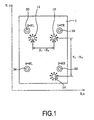
- Fig. 1 is a view showing positions of four dampers and three vertical acceleration sensors of a vehicle employing a semi-active suspension system.
- two vertical acceleration sensors 10 and 12 are mounted adjacent to front dampers 18 and 20 on a vehicle body 1, respectively, while a vertical acceleration sensor 14 is mounted adjacent to one of rear dampers 22 and 24.
- X designates a width direction of the vehicle body
- Y designates a longitudinal direction thereof
- the positions of the two front vertical acceleration sensors 10 and 12 are indicated by coordinates (X 2 , Y 2 ) and (X 1 , Y 1 ), respectively
- the position of the rear vertical acceleration sensor 14 is indicated by coordinates (X 3 , Y 3 ).
- correction constants for a vertical acceleration to be measured at a position where a fourth vertical acceleration sensor would be installed are obtained using the X and Y position coordinate values (for example, X 1 -X 2 and Y 1 -Y 3 ) of the three vertical acceleration sensors 10, 12 and 14.
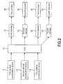
- Fig. 2 is a block diagram of the semi-active suspension system, illustrating a method for measuring a vertical acceleration according to the present invention.
- the semi-active suspension system comprises the first to third vertical acceleration sensors 10, 12 and 14, an ECU 16, the first to fourth dampers 18, 20, 22 and 24, and first to fourth actuators 26, 28, 30 and 32.
- a microprocessor is used for the ECU 16, and the ECU includes control algorithms for bounce, roll, dive, squat and the like based on sky-hook logic for independently controlling damping forces of the dampers of respective road wheels.
- the first to fourth dampers 18, 20, 22 and 24 are equipped with variable valves at lateral sides thereof so as to adjust the damping forces for use in controlling the first to fourth actuators 26, 28, 30 and 32 when the dampers are extended and retracted.
- the method for measuring the vertical acceleration according to the present invention is performed as follows.
- Ad is the fourth vertical acceleration
- Aa1, Aa2 and Aa3 are the first to third vertical accelerations, respectively.
- the fourth vertical acceleration Ad at the position of the fourth damper where a vertical acceleration sensor is not installed is obtained by multiplying the vertical accelerations Aa1, Aa2 and Aa3 measured in the first to third vertical acceleration sensors 10, 12 and 14 by the corresponding correction constants ⁇ , ⁇ and ⁇ and subsequently summing up the first to third accelerations that have been multiplied by the correction constants.
- all the coordinate values of the respective vertical acceleration sensors are included in the equation P .
- A ( Z 1 - Z 2 ) Y 1 - Y 3 - Z 1 - Z 3 ⁇ Y 1 - Y 2 ( X 1 - X 2 ) Y 1 - Y 3 - X 1 - X 3 ⁇ Y 1 - Y 2
- B ( X 1 - X 2 ) Z 1 - Z 3 - X 1 - X 3 ⁇ Z 1 - Z 2 ( X 1 - X 2 ) Y 1 - Y 3 - X 1 - X 3 ⁇ Y 1 - Y 2
- the three vertical acceleration sensors output the accelerations of z ⁇ 1 , z ⁇ 2 and z ⁇ 3 , respectively.
- Equation 8 Since A is a function of Z1, Z2 and Z3 and Z1, Z2, and Z3 are also functions of time, a derivative of A with respect to time is expressed as Equation 8 using a chain rule. Equation 8 can be expressed as Equation 9 by rearranging it according to the accelerations of the respective sensors after expanding Equation 8 with respect to respective coefficients.
- Equation 11 the correction constants ⁇ , ⁇ and ⁇ at the damper positions (x, y) of the dampers are expressed as the following Equation 11.
- a ⁇ Z 2 Y 3 - Y 1 ( X 1 - X 2 ) Y 1 - Y 3 - X 1 - X 3 ⁇ Y 1 - Y 2 ⁇
- a ⁇ Z 2 Y 3 - Y 1 ( X 1 - X 2 ) Y 1 - Y 3 - X 1 - X 3 ⁇ Y 1 - Y 2 ⁇
- a ⁇ Z 3 Y 1 - Y 2 ( X 1 - X 2 ) Y 1 - Y 3 - X 1 - X 3 ⁇ Y 1 - Y 2 ⁇
- a ⁇ Z 3 Y 1 - Y 2 ( X 1 - X 2 )
- Equation 15 the correction constants ⁇ , ⁇ and ⁇ at the position (x, y) of the fourth damper where a vertical acceleration sensor is not installed can be obtained as Equation 15 from the position coordinate values (X 1 , X 2 , X 3 ) and (Y 1 , Y 2 , Y 3 ) of the three vertical acceleration sensors 10, 12 and 14.
- Equation 2 When the correction constants ⁇ , ⁇ and ⁇ obtained from Equation 15 and the vertical accelerations Aa1, Aa2 and Aa3 of the first to third vertical acceleration sensors 10, 12 and 14 are substituted into Equation 2, the ECU 16 can obtain the vertical acceleration Ad at the position of the fourth damper 24 in which a vertical acceleration sensor is not installed.
- the ECU 16 of the present invention corrects the vertical accelerations of the first to third vertical acceleration sensors 10, 12 and 14 to the vertical accelerations at the positions of the first to third dampers 18, 20 and 22 using the following Equation 16.
- Aa n 1 ⁇ 1 ⁇ Aa 1 + ⁇ 1 ⁇ Aa 2 + ⁇ 1 ⁇ Aa 3
- Aa n 2 ⁇ 2 ⁇ Aa 1 + ⁇ 2 ⁇ Aa 2 + ⁇ 2 ⁇ Aa 3
- Aa n 3 ⁇ 3 ⁇ Aa 1 + ⁇ 3 ⁇ Aa 2 + ⁇ 3 ⁇ Aa 3
- Aa n [1], Aa n [2] and Aa n [3] are values corrected to the vertical accelerations at the positions of the first to third dampers.
- ⁇ [1], ⁇ [1] and ⁇ [1] are correction constants at the position of the first damper
- ⁇ [2], ⁇ [2] and ⁇ [2] are correction constants at the position of the second damper
- ⁇ [3], ⁇ [3] and ⁇ [3] are correction constants at the position of the third damper.
- the X and Y position coordinate values of the first to third vertical acceleration sensors are given (1500, 1800), (200, 1800) and (1400, 300) and the x and y position coordinate values of the first to fourth dampers are given (1700, 2000), (0, 2000), (1600, 500) and (100, 500), respectively.
- the correction constants ⁇ , ⁇ and ⁇ at the positions of the respective dampers are obtained.
- the fourth vertical acceleration i.e., the vertical acceleration at the position of the fourth damper can be obtained, which is not shown in Table 1.
- Table 1 1 st Vertical Acceleration Sensor 2 nd Vertical Acceleration Sensor 3 rd Vertical Acceleration Sensor 4 th Vertical Acceleration Vertical Acceleration Sensor X 1500 200 1400 Y 1800 1800 300 Damper x 1700 0 1600 100 y 2000 2000 500 500 ⁇ 0.405 0.030 0.276 0.876 ⁇ 2.471 2.292 -0.143 1.164 ⁇ -0.133 -0.133 0.866 0.866
- the ECU 16 of the present invention outputs signals for controlling the damping forces of the first to fourth dampers 18, 20, 22 and 24 in order to improve the ride comfort of the vehicle according to the values corrected to the vertical accelerations at the positions of the first to fourth dampers using the correction constants ⁇ , ⁇ and ⁇ at the positions of the respective dampers.
- the first to fourth actuators 26, 28, 30 and 32 are operated with the damping forces.
- Fig. 3 is a view showing the positions of the four dampers and three velocity sensors of the vehicle employing the semi-active suspension system.
- two velocity sensors 100 and 102 are mounted adjacent to the front dampers 18 and 20 of the vehicle body 1, respectively, while a velocity sensor 104 is mounted adjacent to one of the rear dampers 22 and 24.
- X designates the width direction of the vehicle body
- Y designates the longitudinal direction thereof
- the positions of the two front velocity sensors 100 and 102 are (X 2 , Y 2 ) and (X 1 , Y 1 ), respectively
- the position of the rear velocity sensor 104 is (X 3 , Y 3 ). Since unexplained reference numerals are the same as those shown in Fig. 1, descriptions thereof will be omitted.
- correction constants for a velocity at a position where a fourth velocity sensor would be installed are obtained using the X and Y position coordinate values (for example, X 1 -X 2 and Y 1 -Y 3 ) among the three velocity sensors 100, 102 and 104.
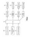
- Fig. 4 is a block diagram of the semi-active suspension system, illustrating a method for measuring a velocity according to the present invention.
- the semi-active suspension system comprises the first to third velocity sensors 100, 102 and 104, the ECU 16, the first to fourth dampers 18, 20, 22 and 24, and the first to fourth actuators 26, 28, 30 and 32.
- the first to third velocity sensors 100, 102 and 104 are sensors installed adjacent to three of the four dampers on the vehicle body so as to measure the velocity of the vehicle.
- the method for measuring the velocity according to the present invention is performed as follows. Meanwhile, since a velocity is obtained by integrating an acceleration in the method for measuring the velocity of the present invention, the same equations as those described in the aforementioned method for measuring the acceleration will be used.
- velocities Va1, Va2 and Va3 measured by the respective first to third velocity sensors 100, 102 and 104 are input into the ECU 16.
- the fourth velocity Vd at the position of the fourth damper where a velocity sensor is not installed is obtained by multiplying the vertical velocities Va1, Va2 and Va3 measured in the first to third velocity sensors 100, 102 and 104 by the corresponding correction constants ⁇ , ⁇ and ⁇ and subsequently summing up the first to third velocities that have been multiplied by the correction constants.
- all the coordinate values of the respective velocity sensors are included in the equation P .
- A ( Z 1 - Z 2 ) Y 1 - Y 3 - Z 1 - Z 3 ⁇ Y 1 - Y 2 ( X 1 - X 2 ) Y 1 - Y 3 - X 1 - X 3 ⁇ Y 1 - Y 2
- B ( X 1 - X 2 ) Z 1 - Z 3 - X 1 - X 3 ⁇ Z 1 - Z 2 ( X 1 - X 2 ) Y 1 - Y 3 - X 1 - X 3 ⁇ Y 1 - Y 2
- the three velocity sensors output the velocities of ⁇ 1 , ⁇ 2 and ⁇ 3 , respectively.
- dz dt dA dt ⁇ x + dB dt ⁇ y + dC dt d
- Equation 23 Since A is a function of Z1, Z2 and Z3 and Z1, Z2, and Z3 are also functions of time, a derivative of A with respect to time is expressed as Equation 23 using a chain rule. That is, Equation 23 can be expressed as Equation 24 by rearranging it according to the velocities of the respective sensors after expanding Equation 23 with respect to respective coefficients.
- Equation 26 the correction constants ⁇ , ⁇ and ⁇ at the damper positions (x, y) of the dampers are expressed as the following Equation 26.
- a ⁇ Z 2 Y 3 - Y 1 ( X 1 - X 2 ) Y 1 - Y 3 - X 1 - X 3 ⁇ Y 1 - Y 2 ⁇
- Equation 30 the correction constants ⁇ , ⁇ and ⁇ at the position (x, y) of the fourth damper where a velocity sensor is not installed can be obtained as Equation 30 from the position coordinate values (X 1 , X 2 , X 3 ) and (Y 1 , Y 2 , Y 3 ) of the three velocity sensors 100, 102 and 104.
- Equation 17 When the correction constants ⁇ , ⁇ and ⁇ obtained from Equation 30 and the velocities Va1, Va2 and Va3 of the first to third velocity sensors 100, 102 and 104 are substituted into Equation 17, the ECU 16 can obtain the velocity Vd at the position of the fourth damper 24 where a velocity sensor is not installed.
- the ECU 16 of the present invention corrects the velocities of the first to third velocity sensors 100, 102 and 104 to the velocities at the positions of the first to third dampers 18, 20 and 22 using the following Equation 31.
- Va n 1 ⁇ 1 ⁇ Va 1 + ⁇ 1 ⁇ Va 2 + ⁇ 1 ⁇ Va 3
- Va n 2 ⁇ 2 ⁇ Va 1 + ⁇ 2 ⁇ Va 2 + ⁇ 2 ⁇ Va 3
- Va n 3 ⁇ 3 ⁇ Va 1 + ⁇ 3 ⁇ Va 2 + ⁇ 3 ⁇ Va 3
- Va n [1], Va n [2] and Va n [3] are values corrected to the velocities at the positions of the first to third dampers.
- ⁇ [1], ⁇ [1] and ⁇ [1] are correction constants at the position of the first damper
- ⁇ [2], ⁇ [2] and ⁇ [2] are correction constants at the position of the second damper
- ⁇ [3], ⁇ [3] and ⁇ [3] are correction constants at the position of the third damper.
- the correction constants ⁇ , ⁇ and ⁇ at the positions of the respective dampers are obtained in the ECU 16 of the present invention. Then, from the correction constants at the position of the fourth damper and the X and Y position coordinate values of the first to third velocity sensors, the fourth velocity, i.e., the velocity at the position of the fourth damper, can be obtained. Further, signals for controlling the damping forces of the first to fourth dampers 18, 20, 22 and 24 are output in order to improve the ride comfort of the vehicle according to the values corrected to the velocities at the positions of the first to fourth dampers. Thus, the first to fourth actuators 26, 28, 30 and 32 are operated with the controlled damping forces.
- the fourth vertical acceleration can be obtained by multiplying the three vertical accelerations measured from the three acceleration sensors by the constants for correcting them to accelerations at actually desired damper positions and subsequently summing up them. Then, by multiplying the vertical accelerations measured from the three acceleration sensors by the correction constants at the corresponding damper positions, the corrected vertical accelerations can be obtained.
- the present invention can be applied to velocity sensors instead of vertical acceleration sensors so as to more correctly control the ride comfort of a vehicle.
Landscapes
- Engineering & Computer Science (AREA)
- Mechanical Engineering (AREA)
- Vehicle Body Suspensions (AREA)
Abstract
Description
- The present invention relates to a semi-active suspension system of a vehicle, and more particularly, to a method for measuring a vertical acceleration of a semi-active suspension system.
- In general, a semi-active suspension system is an apparatus for improving the driving stability and ride comfort of a vehicle by changing the dynamic characteristics of dampers mounted in a vehicle in real time. When a driver excessively steers a vehicle or the movement of the vehicle is out of its path, load unbalance of the vehicle causes the vehicle to be biased or not to be steerable so that the driver may be in unpredictable danger such as vehicle overturn. However, when a vehicle, which is mounted with the semi-active suspension system, drives on an uneven road, a vertical load at a contact surface of a tire and the road is kept at an appropriate level, so that the stability of the vehicle can be secured in steering, braking and driving. In addition, irregular shocks generated from the road when the vehicle travels are effectively absorbed, so that the ride comfort and driving convenience can be provided to a passenger and a driver.
- Such a semi-active suspension system controls actuators and dampers respectively connected to four road wheels after detecting the driving conditions of the vehicle through vertical acceleration sensors, vehicle velocity sensors, a steering angle sensor, a brake sensor, a throttle position sensor, and the like among a variety of sensors mounted to the vehicle.
- Among them, the vertical acceleration sensors are installed adjacent to four dampers. However, since there is a difference between the practical mounting positions of the acceleration sensors and the installation positions of the dampers, it is difficult to accurately measure the accelerations of the road wheels.
- In a prior art, three vertical accelerations are measured through two vertical acceleration sensors mounted in front of a vehicle body and a vertical acceleration sensor mounted at the rear thereof in the vicinity of the respective dampers, and a fourth vertical acceleration is obtained in such a manner that an ECU receives the three vertical accelerations and calculates the other vertical
acceleration using Equation 1 as follows:
where aFL is a vertical acceleration of a front left side, aFR is a vertical acceleration of a front right side, aRL is a vertical acceleration of a rear left side, aRR is a vertical acceleration of a rear right side, tF is a front tread, and tR is a rear tread. - Since it is difficult to accurately obtain a fourth vertical acceleration through calculation using the three vertical accelerations and the threads of the road wheels, there is a problem with accurate determination of the dynamic characteristics of the vehicle.
- Further, in the prior art, there is also a problem in that it is difficult to accurately obtain a velocity even upon calculation thereof from three velocity sensors.
- Accordingly, the present invention is conceived to solve the aforementioned problems in the prior art. An object of the present invention is to provide a method for measuring vertical accelerations of a semi-active suspension system capable of accurately measuring and correcting the vertical accelerations in such a manner that vertical accelerations measured from three acceleration sensors are multiplied by constants for correcting them to accelerations at actually desired positions and are then summed up so as to obtain a fourth vertical acceleration.
- Another object of the present invention is to provide a method for measuring velocities of a semi-active suspension system capable of accurately measuring and correcting the velocities in such a manner that three velocities measured from three velocity sensors are multiplied by constants for correcting them to velocities at actually desired positions and are then summed up so as to obtain a fourth velocity.
- According to an aspect of the present invention for achieving the objects, there is provided a method for obtaining a vertical acceleration from vertical accelerations measured from three vertical acceleration sensors of a semi-active suspension system of a vehicle, comprising the steps of receiving first to third vertical accelerations measured from first to third vertical acceleration sensors; and obtaining a fourth vertical acceleration (Ad) by multiplying the first to third vertical accelerations by correction constants and subsequently summing up them, according to the following equation:

where α, β and γ are the correction constants at the position of a damper where a vertical acceleration sensor is not installed, Ad is the fourth vertical acceleration, and Aa1, Aa2 and Aa3 are the first to third vertical accelerations, respectively. - According to another aspect of the present invention, there is provided a method for obtaining a velocity from velocities measured from three velocity sensors of a semi-active suspension system of a vehicle, comprising the steps of receiving first to third velocities measured from first to third velocity sensors; and obtaining a fourth velocity (Vd) by multiplying the first to third velocities by correction constants and subsequently summing up them, according to the following equation:

where α, β and γ are the correction constants at the position of a damper where a velocity sensor is not installed, Vd is the fourth velocity, and Va1, Va2 and Va3 are the first to third velocities, respectively. - The above and other objects, features and advantages of the present invention will become apparent from the following description of preferred embodiments given in conjunction with the accompanying drawings, in which:
- Fig. 1 is a view showing positions of four dampers and three vertical acceleration sensors of a vehicle employing a semi-active suspension system;
- Fig. 2 is a block diagram of the semi-active suspension system, illustrating a method for measuring a vertical acceleration according to the present invention;
- Fig. 3 is a view showing positions of the four dampers and three velocity sensors of the vehicle employing the semi-active suspension system; and
- Fig. 4 is a block diagram of a semi-active suspension system, illustrating a method for measuring a velocity according to the present invention.
- Hereinafter, preferred embodiments of the present invention will be described in detail with reference to the accompanying drawings.
- Fig. 1 is a view showing positions of four dampers and three vertical acceleration sensors of a vehicle employing a semi-active suspension system. Referring to this figure, two
vertical acceleration sensors front dampers vehicle body 1, respectively, while avertical acceleration sensor 14 is mounted adjacent to one ofrear dampers vertical acceleration sensors vertical acceleration sensor 14 is indicated by coordinates (X3, Y3).Reference numerals 1=FR, 2=FL, 3=RR, and 4=RL, which have not yet been explained, designate the positions of thefirst damper 18 at the front left side, thesecond damper 20 at the front right side, thethird damper 22 at the rear left side, and thefourth damper 24 at the rear right side, respectively. - In the present invention, correction constants for a vertical acceleration to be measured at a position where a fourth vertical acceleration sensor would be installed are obtained using the X and Y position coordinate values (for example, X1-X2 and Y1-Y3) of the three
vertical acceleration sensors - Fig. 2 is a block diagram of the semi-active suspension system, illustrating a method for measuring a vertical acceleration according to the present invention. Referring to this figure, the semi-active suspension system comprises the first to third
vertical acceleration sensors ECU 16, the first tofourth dampers fourth actuators - Each of the first to third
vertical acceleration sensors - A microprocessor is used for the
ECU 16, and the ECU includes control algorithms for bounce, roll, dive, squat and the like based on sky-hook logic for independently controlling damping forces of the dampers of respective road wheels. - The first to
fourth dampers fourth actuators - In the semi-active suspension system configured as above, the method for measuring the vertical acceleration according to the present invention is performed as follows.
- Vertical accelerations Aa1, Aa2 and Aa3 measured by the respective first to third
vertical acceleration sensors ECU 16. - The
ECU 16 receives the vertical accelerations Aa1, Aa2 and Aa3 measured by the respective first to thirdvertical acceleration sensors Ad using Equation 2 as follows:
where α, β and γ are correction constants for the position of the fourth damper where a fourth vertical acceleration sensor is not installed . Ad is the fourth vertical acceleration, and Aa1, Aa2 and Aa3 are the first to third vertical accelerations, respectively. - Referring to
Equation 2, the fourth vertical acceleration Ad at the position of the fourth damper where a vertical acceleration sensor is not installed is obtained by multiplying the vertical accelerations Aa1, Aa2 and Aa3 measured in the first to thirdvertical acceleration sensors - At this time, the correction constants α, β and γ are obtained from the following procedures.
- For example, assuming that a plane equation P for the vertical acceleration sensors installed on the vehicle body is Z = AX + BY + C, all the coordinate values of the respective vertical acceleration sensors are included in the equation P.

where A, B and C are constants, which are expressed as the followingEquations 4 to 6, respectively.


- At this time, assuming that the installation positions of the three vertical acceleration sensors are upper points on the dampers and in a common plane and Y coordinate values of the front first and second vertical acceleration sensors are the same (i.e., Y1=Y2), the three vertical acceleration sensors output the accelerations of z̈1, z̈2 and z̈3, respectively.
- The plane equation for the first to fourth dampers installed on the vehicle body is considered to be z = Ax + By + C, and is then subjected to second differentiation. At this time, the positions of the dampers are expressed using x and
y. 

where
- Since A is a function of Z1, Z2 and Z3 and Z1, Z2, and Z3 are also functions of time, a derivative of A with respect to time is expressed as Equation 8 using a chain rule. Equation 8 can be expressed as Equation 9 by rearranging it according to the accelerations of the respective sensors after expanding Equation 8 with respect to respective coefficients.


- Thus, the correction constants α, β and γ at the damper positions (x, y) of the dampers are expressed as the following Equation 11.

-


Equation 12.
- Further,


- Furthermore,
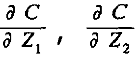

Equation 14.

- When the values obtained from
Equations 12 to 14 are substituted into Equation 11, the correction constants α, β and γ at the position (x, y) of the fourth damper where a vertical acceleration sensor is not installed can be obtained as Equation 15 from the position coordinate values (X1, X2, X3) and (Y1, Y2, Y3) of the threevertical acceleration sensors 
- When the correction constants α, β and γ obtained from Equation 15 and the vertical accelerations Aa1, Aa2 and Aa3 of the first to third
vertical acceleration sensors Equation 2, theECU 16 can obtain the vertical acceleration Ad at the position of thefourth damper 24 in which a vertical acceleration sensor is not installed. - Further, the
ECU 16 of the present invention corrects the vertical accelerations of the first to thirdvertical acceleration sensors third dampers Equation 16.
where Aan[1], Aan[2] and Aan[3] are values corrected to the vertical accelerations at the positions of the first to third dampers. α[1], β[1] and γ[1] are correction constants at the position of the first damper, α[2], β[2] and γ[2] are correction constants at the position of the second damper, and α[3], β[3] and γ[3] are correction constants at the position of the third damper. - For example, as shown in Table 1 below, if the X and Y position coordinate values of the first to third vertical acceleration sensors are given (1500, 1800), (200, 1800) and (1400, 300) and the x and y position coordinate values of the first to fourth dampers are given (1700, 2000), (0, 2000), (1600, 500) and (100, 500), respectively, the correction constants α, β and γ at the positions of the respective dampers are obtained. Then, from the correction constants at the position of the fourth damper and the X and Y position coordinate values of the first to third vertical acceleration sensors, the fourth vertical acceleration, i.e., the vertical acceleration at the position of the fourth damper can be obtained, which is not shown in Table 1.
Table 1 1st Vertical Acceleration Sensor 2nd Vertical Acceleration Sensor 3rd Vertical Acceleration Sensor 4th Vertical Acceleration Vertical Acceleration Sensor X 1500 200 1400 Y 1800 1800 300 Damper x 1700 0 1600 100 y 2000 2000 500 500 α 0.405 0.030 0.276 0.876 β 2.471 2.292 -0.143 1.164 γ -0.133 -0.133 0.866 0.866 - The
ECU 16 of the present invention outputs signals for controlling the damping forces of the first tofourth dampers fourth actuators - Fig. 3 is a view showing the positions of the four dampers and three velocity sensors of the vehicle employing the semi-active suspension system. Referring to Figure 3, two
velocity sensors front dampers vehicle body 1, respectively, while avelocity sensor 104 is mounted adjacent to one of therear dampers front velocity sensors rear velocity sensor 104 is (X3, Y3). Since unexplained reference numerals are the same as those shown in Fig. 1, descriptions thereof will be omitted. - In the present invention, correction constants for a velocity at a position where a fourth velocity sensor would be installed are obtained using the X and Y position coordinate values (for example, X1-X2 and Y1-Y3) among the three
velocity sensors - Fig. 4 is a block diagram of the semi-active suspension system, illustrating a method for measuring a velocity according to the present invention. Referring to this figure, the semi-active suspension system comprises the first to
third velocity sensors ECU 16, the first tofourth dampers fourth actuators third velocity sensors - In the semi-active suspension system configured as above, the method for measuring the velocity according to the present invention is performed as follows. Meanwhile, since a velocity is obtained by integrating an acceleration in the method for measuring the velocity of the present invention, the same equations as those described in the aforementioned method for measuring the acceleration will be used.
- First, velocities Va1, Va2 and Va3 measured by the respective first to
third velocity sensors ECU 16. - The
ECU 16 receives the velocities Va1, Va2 and Va3 measured by the respective first tothird velocity sensors 
where α, β and γ are correction constants for the position of the fourth damper where a fourth velocity sensor is not installed , Vd is the fourth velocity, and Va1, Va2 and Va3 are the first to third velocities, respectively. - Referring to Equation 17, the fourth velocity Vd at the position of the fourth damper where a velocity sensor is not installed is obtained by multiplying the vertical velocities Va1, Va2 and Va3 measured in the first to
third velocity sensors - The correction constants α, β and γ by which the respective velocities are multiplied are obtained as follows.
- For example, assuming that a plane equation P for the velocity sensors installed on the vehicle body is Z = AX + BY + C, all the coordinate values of the respective velocity sensors are included in the equation P.

where A, B and C are constants, which are expressed as the following Equations 19 to 21, respectively.


- At this time, assuming that the installation positions of the three velocity sensors are upper points on the dampers and in a common plane, and Y coordinate values of the front first and second velocity sensors are the same (i.e., Yl=Y2), the three velocity sensors output the velocities of Ż1, Ż2 and Ż3, respectively.
- The plane equation for the first to fourth dampers installed on the vehicle body is considered to be z = Ax + By + C, and is then subjected to first differentiation. At this time, the positions of the dampers are expressed using x and y.


where
- Since A is a function of Z1, Z2 and Z3 and Z1, Z2, and Z3 are also functions of time, a derivative of A with respect to time is expressed as Equation 23 using a chain rule. That is, Equation 23 can be expressed as
Equation 24 by rearranging it according to the velocities of the respective sensors after expanding Equation 23 with respect to respective coefficients.

- Thus, the correction constants α, β and γ at the damper positions (x, y) of the dampers are expressed as the following
Equation 26.

-


Equation 26 and the correction constants α, β and γ can be obtained as the following Equation 27.
- Further,


Equation 26 and the correction constants α, β and γ can be obtained as the followingEquation 28.
- Furthermore,


Equation 26 and the correction constants α, β and γ can be obtained as the following Equation 29.
- When the values obtained from Equations 27 to 29 are substituted into
Equation 26, the correction constants α, β and γ at the position (x, y) of the fourth damper where a velocity sensor is not installed can be obtained asEquation 30 from the position coordinate values (X1, X2, X3) and (Y1, Y2, Y3) of the threevelocity sensors 
- When the correction constants α, β and γ obtained from
Equation 30 and the velocities Va1, Va2 and Va3 of the first tothird velocity sensors ECU 16 can obtain the velocity Vd at the position of thefourth damper 24 where a velocity sensor is not installed. - Further, the
ECU 16 of the present invention corrects the velocities of the first tothird velocity sensors third dampers 
where Van[1], Van[2] and Van[3] are values corrected to the velocities at the positions of the first to third dampers. α[1], β[1] and γ[1] are correction constants at the position of the first damper, α[2], β[2] and γ[2] are correction constants at the position of the second damper, and α[3], β[3] and γ[3] are correction constants at the position of the third damper. - Therefore, when the X and Y position coordinate values of the first to third velocity sensors and the x and y position coordinate values of the first to fourth dampers are given, the correction constants α, β and γ at the positions of the respective dampers are obtained in the
ECU 16 of the present invention. Then, from the correction constants at the position of the fourth damper and the X and Y position coordinate values of the first to third velocity sensors, the fourth velocity, i.e., the velocity at the position of the fourth damper, can be obtained. Further, signals for controlling the damping forces of the first tofourth dampers fourth actuators - As described above, according to the present invention, the fourth vertical acceleration can be obtained by multiplying the three vertical accelerations measured from the three acceleration sensors by the constants for correcting them to accelerations at actually desired damper positions and subsequently summing up them. Then, by multiplying the vertical accelerations measured from the three acceleration sensors by the correction constants at the corresponding damper positions, the corrected vertical accelerations can be obtained.
- Thus, according to the present invention, vertical accelerations at the positions of the dampers can be obtained and the vertical accelerations measured from the sensors can be corrected using the correction constants, so that there is an advantage in that the ride comfort of a vehicle can be more correctly controlled using the corrected vertical accelerations.
- In addition, the present invention can be applied to velocity sensors instead of vertical acceleration sensors so as to more correctly control the ride comfort of a vehicle.
- The present invention is not limited to the embodiments described above but may be modified or changed in various manners by those skilled in the art within the scope and the technical spirit of the invention defined by the appended claims.
Claims (6)
- A method for obtaining a vertical acceleration from vertical accelerations measured from three vertical acceleration sensors of a semi-active suspension system of a vehicle, characterised in that it comprises the steps of:receiving first to third vertical accelerations measured from first to third vertical acceleration sensors; andobtaining a fourth vertical acceleration (Ad) by multiplying the first to third vertical accelerations by correction constants and subsequently summing up them, according to the following equation:where α, β and γ are the correction constants at the position of a damper where a vertical acceleration sensor is not installed, Ad is the fourth vertical acceleration, and Aa1, Aa2 and Aa3 are the first to third vertical accelerations, respectively.

- The method as claimed in claim 1,characterised in that the correction constants α, β and γ are obtained from the following equations using X and Y position coordinate values of the first to third vertical acceleration sensors and x and y position coordinate values of the damper where a vertical acceleration sensor is not installed:


where X1, X2 and X3 are X position coordinate values of the first to third vertical acceleration sensors, Y1, Y2 and Y3 are Y position coordinate values of the first to third vertical acceleration sensors, and x and y are X and Y position coordinate values of the damper where a vertical acceleration sensor is not installed. - The method as claimed in claim 1 or 2, characterised in that after the step of obtaining the fourth vertical acceleration, it further comprises the step of correcting the first to third vertical accelerations measured from the vertical acceleration sensors to vertical accelerations at the positions of corresponding dampers using the following equations:


where Aan [1], Aan[2] and Aan[3] are values corrected to the vertical accelerations at the positions of first to third dampers, α[1], β[1] and γ[1] are correction constants at the position of the first damper, α[2], β[2] and γ[2] are correction constants at the position of the second damper, and α[3], β[3] and γ[3] are correction constants at the position of the third damper. - A method for obtaining a velocity from velocities measured from three velocity sensors of a semi-active suspension system of a vehicle, characterised in that it comprises the steps of:receiving first to third velocities measured from first to third velocity sensors; andobtaining a fourth velocity (Vd) by multiplying the first to third velocities by correction constants and subsequently summing up them, according to the following equation:where α, β and γ are the correction constants at the position of a damper where a velocity sensor is not installed, Vd is the fourth velocity, and Va1, Va2 and Va3 are the first to third velocities, respectively.

- The method as claimed in claim 4,characterised in that the correction constants α, β and γ are obtained from the following equations using X and Y position coordinate values of the first to third velocity sensors and x and y position coordinate values of the damper where a vertical acceleration sensor is not installed:


where X1, X2 and X3 are X position coordinate values of the first to third velocity sensors, Y1, Y2 and Y3 are Y position coordinate values of the first to third velocity sensors, and x and y are X and Y position coordinate values of the damper where a vertical acceleration sensor is not installed. - The method as claimed in claim 4 or 5, characterised in that after the step of obtaining the fourth velocity, it further comprises the step of correcting the first to third velocities measured from the velocity sensors to velocities at the positions of corresponding dampers using the following equations:


where Van[1], Van[2] and Van[3] are values corrected to the velocities at the positions of first to third dampers, α[1], β[1] and γ[1] are correction constants at the position of the first damper, α[2], β[2] and γ[2] are correction constants at the position of the second damper, and α[3], β[3] and γ[3] are correction constants at the position of the third damper.
Priority Applications (2)
| Application Number | Priority Date | Filing Date | Title |
|---|---|---|---|
| EP20050292383 EP1785290B1 (en) | 2005-11-09 | 2005-11-09 | Method for measuring vertical accelaration and velocity of semi-active suspension system |
| DE200560012400 DE602005012400D1 (en) | 2005-11-09 | 2005-11-09 | Method for measuring vertical accelerations and velocities for a semi-active chassis |
Applications Claiming Priority (1)
| Application Number | Priority Date | Filing Date | Title |
|---|---|---|---|
| EP20050292383 EP1785290B1 (en) | 2005-11-09 | 2005-11-09 | Method for measuring vertical accelaration and velocity of semi-active suspension system |
Publications (2)
| Publication Number | Publication Date |
|---|---|
| EP1785290A1 true EP1785290A1 (en) | 2007-05-16 |
| EP1785290B1 EP1785290B1 (en) | 2009-01-14 |
Family
ID=36203768
Family Applications (1)
| Application Number | Title | Priority Date | Filing Date |
|---|---|---|---|
| EP20050292383 Expired - Lifetime EP1785290B1 (en) | 2005-11-09 | 2005-11-09 | Method for measuring vertical accelaration and velocity of semi-active suspension system |
Country Status (2)
| Country | Link |
|---|---|
| EP (1) | EP1785290B1 (en) |
| DE (1) | DE602005012400D1 (en) |
Cited By (1)
| Publication number | Priority date | Publication date | Assignee | Title |
|---|---|---|---|---|
| EP2052888A3 (en) * | 2007-10-26 | 2014-08-20 | Volkswagen Aktiengesellschaft | Method and system for affecting the movement of a vehicle structure on a powered vehicle and vehicle controlled or regulated by its movement processes |
Citations (4)
| Publication number | Priority date | Publication date | Assignee | Title |
|---|---|---|---|---|
| EP0392507A2 (en) * | 1989-04-14 | 1990-10-17 | Toyota Jidosha Kabushiki Kaisha | A hydraulic active suspension system for a vehicle for controlling the attitude of vehicle body responding to lateral acceleration |
| US5408411A (en) | 1991-01-18 | 1995-04-18 | Hitachi, Ltd. | System for predicting behavior of automotive vehicle and for controlling vehicular behavior based thereon |
| EP1226986A1 (en) * | 2001-01-29 | 2002-07-31 | Ford Global Technologies, Inc. | Load estimator |
| DE10320809A1 (en) * | 2003-05-08 | 2004-11-25 | Conti Temic Microelectronic Gmbh | Car motion recognition and monitoring procedure processes data from acceleration, speed, force and body noise sensors using pattern recognition based on state vectors |
-
2005
- 2005-11-09 DE DE200560012400 patent/DE602005012400D1/en not_active Expired - Lifetime
- 2005-11-09 EP EP20050292383 patent/EP1785290B1/en not_active Expired - Lifetime
Patent Citations (4)
| Publication number | Priority date | Publication date | Assignee | Title |
|---|---|---|---|---|
| EP0392507A2 (en) * | 1989-04-14 | 1990-10-17 | Toyota Jidosha Kabushiki Kaisha | A hydraulic active suspension system for a vehicle for controlling the attitude of vehicle body responding to lateral acceleration |
| US5408411A (en) | 1991-01-18 | 1995-04-18 | Hitachi, Ltd. | System for predicting behavior of automotive vehicle and for controlling vehicular behavior based thereon |
| EP1226986A1 (en) * | 2001-01-29 | 2002-07-31 | Ford Global Technologies, Inc. | Load estimator |
| DE10320809A1 (en) * | 2003-05-08 | 2004-11-25 | Conti Temic Microelectronic Gmbh | Car motion recognition and monitoring procedure processes data from acceleration, speed, force and body noise sensors using pattern recognition based on state vectors |
Cited By (2)
| Publication number | Priority date | Publication date | Assignee | Title |
|---|---|---|---|---|
| EP2052888A3 (en) * | 2007-10-26 | 2014-08-20 | Volkswagen Aktiengesellschaft | Method and system for affecting the movement of a vehicle structure on a powered vehicle and vehicle controlled or regulated by its movement processes |
| DE102007051204B4 (en) | 2007-10-26 | 2018-12-20 | Volkswagen Ag | Method and device for determining movement quantities, in particular body movements, of a body |
Also Published As
| Publication number | Publication date |
|---|---|
| EP1785290B1 (en) | 2009-01-14 |
| DE602005012400D1 (en) | 2009-03-05 |
Similar Documents
| Publication | Publication Date | Title |
|---|---|---|
| US7421954B2 (en) | Active suspension controller | |
| US6654674B2 (en) | Enhanced system for yaw stability control system to include roll stability control function | |
| KR102356289B1 (en) | vehicle control unit | |
| CN102198833B (en) | The method determining the normal acceleration of body, longitudinal angle acceleration and lateral angular acceleration | |
| US8032282B2 (en) | Damping characteristics control apparatus for a vehicle suspension | |
| US8755970B2 (en) | Vehicle control device | |
| GB2414815A (en) | Determining lateral velocity and yaw rate of a vehicle | |
| JP3329457B2 (en) | Signal generation system for open-loop or closed-loop control of an open-loop or closed-loop controllable chassis | |
| US12434524B2 (en) | Slip state detection apparatus and suspension control apparatus | |
| KR20060056563A (en) | Variable damper control method of vehicle | |
| JP6426698B2 (en) | Method for reducing the overturning risk of a motor vehicle having a controllable suspension system | |
| US11292309B2 (en) | Damper control system for vehicle | |
| US7627408B2 (en) | Method for measuring vertical acceleration and velocity of semi-active suspension system | |
| EP1785290B1 (en) | Method for measuring vertical accelaration and velocity of semi-active suspension system | |
| US20060178799A1 (en) | Enhanced roll control system | |
| JP6264047B2 (en) | Vehicle system vibration control device | |
| KR100558518B1 (en) | How to measure vertical acceleration and speed of semi-active suspension | |
| KR100880110B1 (en) | Fault detection method of active geometry control suspension | |
| JP2997975B2 (en) | Vehicle suspension control device | |
| CN100500460C (en) | Assaying method of vertical acceleration and speed of semi-automatic suspension system | |
| JP2021039001A (en) | Vehicle loading weight detection method and vehicle loading weight detection device | |
| KR100517207B1 (en) | Electronic control suspension for adopting reverse damper | |
| KR100381773B1 (en) | How to Control Anti-Roll of Vehicles | |
| JP2015067163A (en) | Suspension control device | |
| JP2007302111A (en) | Suspension control device |
Legal Events
| Date | Code | Title | Description |
|---|---|---|---|
| PUAI | Public reference made under article 153(3) epc to a published international application that has entered the european phase |
Free format text: ORIGINAL CODE: 0009012 |
|
| AK | Designated contracting states |
Kind code of ref document: A1 Designated state(s): AT BE BG CH CY CZ DE DK EE ES FI FR GB GR HU IE IS IT LI LT LU LV MC NL PL PT RO SE SI SK TR |
|
| AX | Request for extension of the european patent |
Extension state: AL BA HR MK YU |
|
| 17P | Request for examination filed |
Effective date: 20070821 |
|
| 17Q | First examination report despatched |
Effective date: 20071008 |
|
| AKX | Designation fees paid |
Designated state(s): DE FR GB IT |
|
| GRAP | Despatch of communication of intention to grant a patent |
Free format text: ORIGINAL CODE: EPIDOSNIGR1 |
|
| GRAC | Information related to communication of intention to grant a patent modified |
Free format text: ORIGINAL CODE: EPIDOSCIGR1 |
|
| GRAS | Grant fee paid |
Free format text: ORIGINAL CODE: EPIDOSNIGR3 |
|
| GRAA | (expected) grant |
Free format text: ORIGINAL CODE: 0009210 |
|
| AK | Designated contracting states |
Kind code of ref document: B1 Designated state(s): DE FR GB IT |
|
| REG | Reference to a national code |
Ref country code: GB Ref legal event code: FG4D |
|
| REF | Corresponds to: |
Ref document number: 602005012400 Country of ref document: DE Date of ref document: 20090305 Kind code of ref document: P |
|
| PLBE | No opposition filed within time limit |
Free format text: ORIGINAL CODE: 0009261 |
|
| STAA | Information on the status of an ep patent application or granted ep patent |
Free format text: STATUS: NO OPPOSITION FILED WITHIN TIME LIMIT |
|
| 26N | No opposition filed |
Effective date: 20091015 |
|
| GBPC | Gb: european patent ceased through non-payment of renewal fee |
Effective date: 20091109 |
|
| REG | Reference to a national code |
Ref country code: FR Ref legal event code: ST Effective date: 20100730 |
|
| PG25 | Lapsed in a contracting state [announced via postgrant information from national office to epo] |
Ref country code: FR Free format text: LAPSE BECAUSE OF NON-PAYMENT OF DUE FEES Effective date: 20091130 |
|
| PG25 | Lapsed in a contracting state [announced via postgrant information from national office to epo] |
Ref country code: GB Free format text: LAPSE BECAUSE OF NON-PAYMENT OF DUE FEES Effective date: 20091109 |
|
| PG25 | Lapsed in a contracting state [announced via postgrant information from national office to epo] |
Ref country code: IT Free format text: LAPSE BECAUSE OF FAILURE TO SUBMIT A TRANSLATION OF THE DESCRIPTION OR TO PAY THE FEE WITHIN THE PRESCRIBED TIME-LIMIT Effective date: 20090114 |
|
| REG | Reference to a national code |
Ref country code: DE Ref legal event code: R082 Ref document number: 602005012400 Country of ref document: DE Representative=s name: CBDL PATENTANWAELTE GBR, DE Ref country code: DE Ref legal event code: R082 Ref document number: 602005012400 Country of ref document: DE Representative=s name: CBDL PATENTANWAELTE EGBR, DE |
|
| PGFP | Annual fee paid to national office [announced via postgrant information from national office to epo] |
Ref country code: DE Payment date: 20230822 Year of fee payment: 19 |
|
| REG | Reference to a national code |
Ref country code: DE Ref legal event code: R119 Ref document number: 602005012400 Country of ref document: DE |
|
| PG25 | Lapsed in a contracting state [announced via postgrant information from national office to epo] |
Ref country code: DE Free format text: LAPSE BECAUSE OF NON-PAYMENT OF DUE FEES Effective date: 20250603 |