EP1785230A2 - Apparatus and method for slurry cleaning of etch chambers - Google Patents
Apparatus and method for slurry cleaning of etch chambers Download PDFInfo
- Publication number
- EP1785230A2 EP1785230A2 EP06255599A EP06255599A EP1785230A2 EP 1785230 A2 EP1785230 A2 EP 1785230A2 EP 06255599 A EP06255599 A EP 06255599A EP 06255599 A EP06255599 A EP 06255599A EP 1785230 A2 EP1785230 A2 EP 1785230A2
- Authority
- EP
- European Patent Office
- Prior art keywords
- abrasive slurry
- atomized
- atomizing
- slurry
- fluid
- Prior art date
- Legal status (The legal status is an assumption and is not a legal conclusion. Google has not performed a legal analysis and makes no representation as to the accuracy of the status listed.)
- Granted
Links
Images
Classifications
-
- B—PERFORMING OPERATIONS; TRANSPORTING
- B24—GRINDING; POLISHING
- B24C—ABRASIVE OR RELATED BLASTING WITH PARTICULATE MATERIAL
- B24C5/00—Devices or accessories for generating abrasive blasts
- B24C5/02—Blast guns, e.g. for generating high velocity abrasive fluid jets for cutting materials
- B24C5/04—Nozzles therefor
-
- H—ELECTRICITY
- H10—SEMICONDUCTOR DEVICES; ELECTRIC SOLID-STATE DEVICES NOT OTHERWISE PROVIDED FOR
- H10P—GENERIC PROCESSES OR APPARATUS FOR THE MANUFACTURE OR TREATMENT OF DEVICES COVERED BY CLASS H10
- H10P95/00—Generic processes or apparatus for manufacture or treatments not covered by the other groups of this subclass
-
- B—PERFORMING OPERATIONS; TRANSPORTING
- B24—GRINDING; POLISHING
- B24C—ABRASIVE OR RELATED BLASTING WITH PARTICULATE MATERIAL
- B24C11/00—Selection of abrasive materials or additives for abrasive blasts
- B24C11/005—Selection of abrasive materials or additives for abrasive blasts of additives, e.g. anti-corrosive or disinfecting agents in solid, liquid or gaseous form
-
- B—PERFORMING OPERATIONS; TRANSPORTING
- B24—GRINDING; POLISHING
- B24C—ABRASIVE OR RELATED BLASTING WITH PARTICULATE MATERIAL
- B24C3/00—Abrasive blasting machines or devices; Plants
- B24C3/32—Abrasive blasting machines or devices; Plants designed for abrasive blasting of particular work, e.g. the internal surfaces of cylinder blocks
- B24C3/325—Abrasive blasting machines or devices; Plants designed for abrasive blasting of particular work, e.g. the internal surfaces of cylinder blocks for internal surfaces, e.g. of tubes
-
- B—PERFORMING OPERATIONS; TRANSPORTING
- B24—GRINDING; POLISHING
- B24C—ABRASIVE OR RELATED BLASTING WITH PARTICULATE MATERIAL
- B24C7/00—Equipment for feeding abrasive material; Controlling the flowability, constitution, or other physical characteristics of abrasive blasts
- B24C7/0007—Equipment for feeding abrasive material; Controlling the flowability, constitution, or other physical characteristics of abrasive blasts the abrasive material being fed in a liquid carrier
- B24C7/0038—Equipment for feeding abrasive material; Controlling the flowability, constitution, or other physical characteristics of abrasive blasts the abrasive material being fed in a liquid carrier the blasting medium being a gaseous stream
-
- H—ELECTRICITY
- H10—SEMICONDUCTOR DEVICES; ELECTRIC SOLID-STATE DEVICES NOT OTHERWISE PROVIDED FOR
- H10P—GENERIC PROCESSES OR APPARATUS FOR THE MANUFACTURE OR TREATMENT OF DEVICES COVERED BY CLASS H10
- H10P72/00—Handling or holding of wafers, substrates or devices during manufacture or treatment thereof
- H10P72/04—Apparatus for manufacture or treatment
- H10P72/0402—Apparatus for fluid treatment
- H10P72/0406—Apparatus for fluid treatment for cleaning followed by drying, rinsing, stripping, blasting or the like
- H10P72/0411—Apparatus for fluid treatment for cleaning followed by drying, rinsing, stripping, blasting or the like for wet cleaning or washing
- H10P72/0414—Apparatus for fluid treatment for cleaning followed by drying, rinsing, stripping, blasting or the like for wet cleaning or washing using mainly spraying means, e.g. nozzles
Definitions
- the invention is directed to cleaning apparatus and methods, particularly, but not limited to, apparatus and methods for cleaning products and chambers made during semiconductor manufacturing.
- Removal of contaminants from etch chamber components traditionally uses carbon dioxide pellet blasting, abrasive bead blasting, solvents, strong oxidizers, inorganic acids/bases or high temperature thermal decomposition. Depending on the contaminant/substrate combination, these produce marginal results in contaminant removal and providing high cleanliness surfaces for chamber reuse. These methods may also damage the substrate during the cleaning process particularly when using conventional mechanical cleaning methods for anodized and coated aluminum substrates. More recent designs of chamber components make use of plasma sprayed dielectric coatings such as Al 2 O 3 , ZrO 2 , and Y 2 O 3 . These coatings are applied to ceramic and anodized aluminum substrates where coating adhesion is marginal at best and are easily damaged during cleaning due to the aggressive nature of conventional abrasive blasting techniques.
- a first aspect of the invention provides apparatus, preferably, but not limited to, slurry cleaning apparatus, comprising:
- This apparatus is particularly suitable for slurry cleaning of a semiconductor etching chamber and/or chamber components.
- Apparatus within the invention include those wherein the container may have an agitator or other mixing device adapted to maintain the abrasive particles well dispersed.
- Well dispersed means that the abrasive slurry may be a homogenous mixture of all ingredients.
- the source of atomizing fluid may be selected from a membrane unit, an absorption unit, a cryogenic unit, a container of fluid, a compressor, a pipeline, a gas cabinet, and combinations thereof.
- the source of atomizing fluid may comprise a source of one or more inert gases and combinations thereof.
- the inert gas may be selected from any gas that would be considered inert for the cleaning process, including, but not limited to, nitrogen, argon, air, nitrogen enriched air, noble gases other than argon, and combinations thereof.
- the atomizing head may comprise a venturi.
- Apparatus may comprise a pressure regulator adapted to adjust pressure of the atomizing fluid entering the atomizing head.
- the pressure regulator may be adapted to adjust pressure of the atomized abrasive slurry exiting the atomizing head.
- Another aspect of the invention provides a method of cleaning, comprising directing an atomized abrasive slurry onto at least one internal surface of a semiconductor etching chamber or chamber components.
- Methods of the invention include those wherein the pressure of the atomized abrasive slurry is controlled.
- the pressure may be controlled within a pressure ranging from about 25 to about 150 psig. Pressures higher than 150 psig may be used if necessary to remove debris and the underlying substrate is not damaged.
- the density of the atomized abrasive slurry may need to be reduced; pressures lower than 25 psig may not be able to provide the desired cleaning efficiency, but may be used if the density of the atomized abrasive slurry is increased.
- Methods of the invention include those methods wherein the density of the atomized abrasive slurry is controlled.
- Several ways are available for controlling density of the atomized slurry, including adding more liquid to the abrasive slurry, reducing the amount and/or density of the abrasive particles in the abrasive slurry, reducing the density of the atomizing fluid and/or increasing its flow rate, and combinations of these.
- the density of the atomized abrasive slurry may be controlled within a density ranging from about 0.01 gm/cc to about 0.2 gm/cc.
- Other methods of the invention include controlling momentum of the atomized abrasive slurry exiting the atomizing head.
- Methods of the invention include controlling momentum of the atomized abrasive slurry at momentum ranging from about 100,000 gm-cm/sec to about 300,000 gm-cm/sec.
- Other methods may include maintaining the abrasive slurry in the abrasive slurry container in well dispersed state, and methods wherein the composition of the abrasive slurry in the container is controlled.
- Apparatus of the invention comprise an atomizing head functioning to produce an atomized abrasive slurry.
- the head comprises an abrasive slurry inlet, an atomizing fluid inlet, and an atomized abrasive slurry outlet.
- the atomizing head may include any internal volume capable of producing an atomized abrasive slurry, including a venturi, a converging-diverging nozzle, a converging nozzle, and other nozzle configurations.
- Apparatus of the present invention are concerned with the third category of atomization.
- Internal atomization is characterized by confinement of the liquid and atomizing fluid in a contacting chamber.
- the mode of introduction of the two fluids into this chamber can vary considerably and has a direct influence on the characteristics of the atomized slurry that exits from the chamber.
- the internal geometry of this chamber also affects the specific characteristics of the liquid/atomizing fluid mixture.
- This mode of atomization generally affords an excellent quality of atomization, that is, an atomized slurry composed of very small slurry droplets with a very narrow droplet size distribution about these small diameters.
- this atomization quality is naturally a function of the atomizing fluid delivery rate employed and the pressure level prevailing in the interior of the atomizing chamber.
- the atomized slurry is created mainly by shearing of the jet of liquid slurry by the atomizing fluid.
- the geometry of the outlets for the two fluids completely determines the quality of the atomization, and droplet size analysis of the drops resulting from the contact may show a relatively wide diameter distribution (simultaneous-presence of small and large droplets).
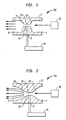
- FIG. 1 is a schematic side elevation view of an embodiment of one apparatus 100 according to the present invention, comprising an atomizing head 2 having an atomizing fluid inlet 4, an abrasive slurry inlet 6, and an atomized abrasive slurry outlet 8.
- Atomizing head 2 may be made from any suitable material or combination of materials, such as metal, plastic, and combinations thereof. Suitable metals include aluminum, stainless steels, such as 304 stainless steel. The stainless steel may be electropolished, but this is not a requirement of the invention.
- the internal flow channels include a converging nozzle 10, a parallel throat section 12, and a diverging nozzle 14.
- Throat 12 includes in this embodiment an inlet port or orifice 16 for abrasive slurry, which is drawn into throat 12 by negative pressure caused by flowing fluidizing fluid.
- Abrasive slurry may be drawn up from one or more abrasive slurry containers 20, and head 2 may have one or more fluid connections to one or more sources of fluidizing fluid 18.
- this particular flow configuration represents a venturi, the invention is not so limited.
- atomizing fluid inlet may be comprised of one, two, or more than two inlet orifices, as may abrasive inlet orifice 16.
- atomizing fluid inlet may be comprised of one, two, or more than two inlet orifices, as may abrasive inlet orifice 16.
- FIG. 2 is a schematic side elevation view of another embodiment of an apparatus 200 according to the present invention, similar to apparatus 100 illustrated in FIG. 1, comprising an atomizing head 22 having an atomizing fluid inlet 4, an abrasive slurry inlet 6, and an atomized abrasive slurry outlet 8.
- the internal flow channels include a more streamlined converging-diverging nozzle 24, 28, and a throat 26.
- Throat 26 also includes in this embodiment an inlet port or orifice 16 for abrasive slurry, which is drawn into throat 26 by negative pressure caused by flowing fluidizing fluid.
- Abrasive slurry may be drawn up from one or more abrasive slurry containers 20, and head 2 may have one or more fluid connections to one or more sources of fluidizing fluid 18.
- the abrasive slurry container fluidly connected to the abrasive slurry inlet of the atomizing head, defines a space for a slurry comprising water, abrasive particles, and other optional ingredients, depending on the particular cleaning task, for example the type and quantity of debris or deposits to be removed, the underlying substrate composition and hardness, and the properties of any substrate coating, such as a refractory or dielectric coating.
- the abrasive slurry container may be under atmospheric pressure, at a slight vacuum, or at a pressure above atmospheric, although the pressure in the container is not critical.
- the container may be closed or open to the atmosphere. If the container is at a pressure less than or greater than atmospheric the container will necessarily be manufactured to withstand these conditions.
- the container may comprise an outer shell with a bladder arrangement, where abrasive slurry is held inside the bladder. Air or other fluid may be used to force slurry out of the bladder, and a vacuum may assist loading the bladder with the abrasive slurry.
- the configuration of the abrasive slurry container is not critical, as long the abrasive particles are able to be kept suspended, or reasonably so, in the container. There may be occasions when there are more abrasive particles than required for a particular task, in which case not all abrasives particles will need to be suspended. Some may be allowed to settle out to the bottom of the container until needed.
- the materials of construction of the slurry container are not critical.
- the container may be metal, plastic, or some combination thereof.
- a refractory or ceramic container may even be used, and a liner may be used.
- the liner may be a ceramic or plastic material.
- Suspension aids may be used. These may be chemical, mechanical or combination thereof.
- a mechanical suspension aide may comprise one or more stirring or agitating device.
- a chemical suspension aide may comprise one or more suspension aide chemicals. Examples of these latter are discussed further herein.
- a source of atomizing fluid is fluidly connected to the atomizing fluid inlet.
- the source of atomizing fluid is selected from a membrane unit, an absorption unit, a cryogenic unit, a container of fluid, a compressor, a pipeline, a gas cabinet, and combinations thereof.
- the source of atomizing fluid may comprise a source of one or more inert gases and combinations thereof. If used, the inert gas may be selected from sources of nitrogen, argon, air, nitrogen enriched air, noble gases other than argon, and combinations and mixtures thereof.
- the atomizing fluid need not be a pure gas.
- the atomizing fluid may be air, or nitrogen generated by a membrane separation unit producing nitrogen enriched air.
- the source of atomizing fluid is fluidly connected to the atomizing head by one or more conduits, which may include one or more pressure regulators adapted to adjust pressure of the atomizing fluid as it enters the atomizing head.
- the pressure regulator may be adapted to adjust pressure of the atomized abrasive slurry as well.
- the pressure of the source of atomizing fluid may be any pressure required to atomize a particular slurry and perform the cleaning function.
- the pressure of the source of atomizing fluid may be controlled, such as by use of a gas cabinet, or it may be taken from a pipeline where there is little control over the pressure of the atomizing fluid in the pipeline.
- an atomized abrasive slurry is directed onto at least one, preferably more than one internal surface of a semiconductor etching chamber.
- the method may include generating the atomized abrasive slurry by flowing an atomizing fluid through the atomizing head.
- Generating the atomized abrasive slurry may comprise controlling pressure of the atomized abrasive slurry exiting the atomizing head at a pressure ranging from about 25 to about 150 psig.
- the generating step may comprise controlling density of the atomized abrasive slurry to a density ranging from about 0.01 gm/cc to about 0.2 gm/cc.
- the momentum of the atomized abrasive slurry at the workpiece may be controlled by controlling the momentum of the atomized abrasive slurry as it exits the atomizing head.
- the momentum of the atomized abrasive slurry exiting the atomizing head may be controlled with in a range of from about 100,000 gm-cm/sec to about 300,000 gm-cm/sec.
- the momentum of the atomized abrasive slurry as it exits the atomizing head may be controlled by adjusting the pressure of the atomizing fluid as it enters the atomizing head, the amount of slurry entering the atomizing head, the density of the abrasive slurry, or any combination of these.
- the abrasive slurry may be maintained in a well-dispersed state in the abrasive slurry container.
- this means the abrasive slurry may be a homogenous mixture of all ingredients.
- Abrasive particles useful in the invention may be selected from those commonly used in the abrasive art, however, the abrasive particles (size and composition) will be chosen with the degree of surface roughness, coating thickness change, and adhesion properties in mind. In choosing an appropriate abrasive particle, characteristics such as hardness, compatibility with the intended workpiece, particle size, reactivity with the workpiece, as well as heat conductivity may be considered.
- composition of abrasive particles can be divided into two classes: natural abrasives and manufactured abrasives.
- natural abrasives include: diamond, corundum, emery, garnet, buhrstone, chert, quartz, sandstone, chalcedony, flint, quartzite, silica, feldspar, pumice and talc.
- Examples of manufactured abrasives include: boron carbide, cubic boron nitride, fused alumina, ceramic aluminum oxide, heat treated aluminum oxide, alumina zirconia, glass, silicon carbide, iron oxides, tantalum carbide, cerium oxide, tin oxide, titanium carbide, synthetic diamond, manganese dioxide, zirconium oxide, and silicon nitride.
- Abrasive particles preferably have a particle size ranging from about 0.1 micrometer to about 1500 micrometers, more preferably ranging from about 0.1 micrometer to about 1300 micrometers.
- the abrasive particles preferably have an average particle size ranging from about 0.1 micrometer to about 700 micrometers, more preferably ranging from about 1 to about 150 micrometers, particularly preferably from about 1 to about 80 micrometers. It is preferred that abrasive particles have a Moh's hardness of at least 8, more preferably above 9; however, for specific applications, softer particles may be used.
- abrasive particle includes agglomerates of individual abrasive particles.
- An abrasive agglomerate is formed when a plurality of abrasive particles are bonded together with a binder to form a larger abrasive particle which may have a specific particulate structure.
- the plurality of particles which form the abrasive agglomerate may comprise more than one type of abrasive particle and a binder.
- fillers are inorganic particulate matter which comprise apparatus which are substantially inert or non-reactive with respect to the surface acted upon by the abrasive.
- active (i.e. reactive) fillers are used, sometimes referred to in the abrasives art as grinding aids.
- These fillers interact beneficially with the workpiece during use.
- the grinding aid may either 1) decrease the friction between the abrasive particles and the workpiece being abraded, 2) prevent the abrasive particle from "capping", i.e. prevent metal particles from becoming welded to the tops of the abrasive particles, 3) decrease the interface temperature between the abrasive particles and the workpiece or 4) decrease the required grinding force.
- Grinding aids encompass a wide variety of different materials and can be inorganic or organic based.
- chemical groups of grinding aids include waxes, organic halide compounds, halide salts and metals and their alloys.
- the organic halide compounds will typically break down during abrading and release a halogen acid or a gaseous halide compound.
- examples of such materials include chlorinated waxes like tetrachloronaphthalene, pentachloronaphthalene; and polyvinyl chloride.
- halide salts include sodium chloride, potassium cryolite, sodium cryolite, ammonium cryolite, potassium tetrafluoroborate, sodium tetrafluoroborate, silicon fluorides, potassium chloride, magnesium chloride.
- metals include, tin, lead, bismuth, cobalt, antimony, cadmium, iron titanium.
- Other miscellaneous grinding aids include sulfur, organic sulfur compounds, graphite and metallic sulfides. It is also within the scope of this invention to use a combination of different grinding aids and in some instances this may produce a synergistic effect.
- the above mentioned examples of grinding aids is meant to be a representative showing of grinding aids, and it is not meant to encompass all grinding aids.
- Grinding aids may be used in abrasive slurries in amounts ranging from about 0.1 to about 10 dry weight percent, more preferably from about 0.5 to about 5.0 weight percent, based on total weight of slurry. If non-reactive fillers are employed they may be used up to 50 dry weight percent.
- Abrasive slurries may contain any number of conventional additives such as one or more additional components, such as, for example, plasticizer, chelating agent, pH modifier, defoamer, foaming agent, reinforcing polymer, anti-freeze agent, suspension aid, bactericide, fungicide, and/or thickener.
- additional components such as, for example, plasticizer, chelating agent, pH modifier, defoamer, foaming agent, reinforcing polymer, anti-freeze agent, suspension aid, bactericide, fungicide, and/or thickener.
- Abrasive slurries may be prepared by mixing abrasive particles having known particle size ranging from 5 micrometers and known particle size distribution ranging from 1-75 micrometers with deionized water, and optionally other materials, to achieve slurry density ranging from about 0.01 gm/cc to about 0.2 gm/cc.
- the slurry may be mixed for 20 minutes at 1200 rpm using a high shear mixer, and the mixer may be left on during use of the slurry, but at lower rpm, in order to maintain a well dispersed slurry.
- the abrasive slurry may be converted into an atomized spray using an atomizing head having a venturi, similar to that illustrated schematically in FIG. 1.
- the atomizing head may be manufactured out of aluminum, and may have one or more slurry inlet orifices of diameter of about 1 cm, one or more air (atomizing fluid) inlet orifices of diameter of 1 cm, and one or more atomized slurry outlet orifices having a diameter of 2 cm.
- the abrasive slurry may be fed to the atomizing head through a flexible stainless steel tube, the abrasive slurry drawn into the atomizing head by air entering the atomizing head at a pressure of about 100 psig.
- the atomized slurry emerges from the atomizing head at a pressure of about 50 psig.
- the slurry tank may be maintained stirred as mentioned above.
- the slurry tank may be at atmospheric pressure and room temperature, although these conditions are simply convenient and not required.
- the atomized slurry may be directed at dielectric-coated surfaces of an etch chamber having deposits of silicon, silicon carbide, and other debris on the dielectric surface.
- the atomized slurry may be directed at the surfaces at a 90° angle, although other angles may be used.
- the pre-test roughness (Ra) of the dielectric surfaces are measured, as well as the post-test roughness after 30 seconds of contacting the atomized slurry to the dielectric surfaces.
- Ra is a common measure of roughness used in the abrasives industry. “Ra” is defined as the arithmetic mean of the departures of the roughness profile from the mean line. Ra may be measured with a profilometer probe, which has a diamond tipped stylus. In general, the lower the Ra value, the smoother or finer the workpiece surface finish. The profilometer known under the trade designation Perthen M4P may be used. Thickness of coatings may be determined by microsection techniques known in the art.
- Apparatus and methods of the present invention may to be used to effectively remove debris from surfaces of semiconductor etching chambers.
Landscapes
- Engineering & Computer Science (AREA)
- Mechanical Engineering (AREA)
- Cleaning Or Drying Semiconductors (AREA)
- Cleaning By Liquid Or Steam (AREA)
- Grinding-Machine Dressing And Accessory Apparatuses (AREA)
- Finish Polishing, Edge Sharpening, And Grinding By Specific Grinding Devices (AREA)
- Mechanical Treatment Of Semiconductor (AREA)
- Coating By Spraying Or Casting (AREA)
- Nozzles (AREA)
Abstract
Description
- The invention is directed to cleaning apparatus and methods, particularly, but not limited to, apparatus and methods for cleaning products and chambers made during semiconductor manufacturing.
- Removal of contaminants from etch chamber components traditionally uses carbon dioxide pellet blasting, abrasive bead blasting, solvents, strong oxidizers, inorganic acids/bases or high temperature thermal decomposition. Depending on the contaminant/substrate combination, these produce marginal results in contaminant removal and providing high cleanliness surfaces for chamber reuse. These methods may also damage the substrate during the cleaning process particularly when using conventional mechanical cleaning methods for anodized and coated aluminum substrates. More recent designs of chamber components make use of plasma sprayed dielectric coatings such as Al2O3, ZrO2, and Y2O3. These coatings are applied to ceramic and anodized aluminum substrates where coating adhesion is marginal at best and are easily damaged during cleaning due to the aggressive nature of conventional abrasive blasting techniques.
- Clearly there is a real need for effective removal of deposits from all surfaces used during the process of creating a semiconductor wafer without degrading or damaging the substrate or coating surface.
- A first aspect of the invention provides apparatus, preferably, but not limited to, slurry cleaning apparatus, comprising:
- (a) an atomizing head adapted to produce an atomized abrasive slurry, the head having an abrasive slurry inlet, an atomizing fluid inlet, and an atomized abrasive slurry outlet;
- (b) an abrasive slurry container fluidly connected to the abrasive slurry inlet and defining a space for a slurry comprising water and abrasive particles; and
- (c) a source of atomizing fluid fluidly connected to the atomizing fluid inlet.
- This apparatus is particularly suitable for slurry cleaning of a semiconductor etching chamber and/or chamber components.
- Apparatus within the invention include those wherein the container may have an agitator or other mixing device adapted to maintain the abrasive particles well dispersed. "Well dispersed", as used herein, means that the abrasive slurry may be a homogenous mixture of all ingredients. The source of atomizing fluid may be selected from a membrane unit, an absorption unit, a cryogenic unit, a container of fluid, a compressor, a pipeline, a gas cabinet, and combinations thereof. The source of atomizing fluid may comprise a source of one or more inert gases and combinations thereof. The inert gas may be selected from any gas that would be considered inert for the cleaning process, including, but not limited to, nitrogen, argon, air, nitrogen enriched air, noble gases other than argon, and combinations thereof. The atomizing head may comprise a venturi. Apparatus may comprise a pressure regulator adapted to adjust pressure of the atomizing fluid entering the atomizing head. The pressure regulator may be adapted to adjust pressure of the atomized abrasive slurry exiting the atomizing head.
- Another aspect of the invention provides a method of cleaning, comprising directing an atomized abrasive slurry onto at least one internal surface of a semiconductor etching chamber or chamber components. Methods of the invention include those wherein the pressure of the atomized abrasive slurry is controlled. The pressure may be controlled within a pressure ranging from about 25 to about 150 psig. Pressures higher than 150 psig may be used if necessary to remove debris and the underlying substrate is not damaged. The density of the atomized abrasive slurry may need to be reduced; pressures lower than 25 psig may not be able to provide the desired cleaning efficiency, but may be used if the density of the atomized abrasive slurry is increased. Methods of the invention include those methods wherein the density of the atomized abrasive slurry is controlled. Several ways are available for controlling density of the atomized slurry, including adding more liquid to the abrasive slurry, reducing the amount and/or density of the abrasive particles in the abrasive slurry, reducing the density of the atomizing fluid and/or increasing its flow rate, and combinations of these. The density of the atomized abrasive slurry may be controlled within a density ranging from about 0.01 gm/cc to about 0.2 gm/cc. Other methods of the invention include controlling momentum of the atomized abrasive slurry exiting the atomizing head. Methods of the invention include controlling momentum of the atomized abrasive slurry at momentum ranging from about 100,000 gm-cm/sec to about 300,000 gm-cm/sec. Other methods may include maintaining the abrasive slurry in the abrasive slurry container in well dispersed state, and methods wherein the composition of the abrasive slurry in the container is controlled.
- Preferred features of the present invention will now be described, by way of example only, with reference to the accompanying drawings, in which:
- FIGS. 1 and 2 are schematic side elevation views of first and second apparatus embodiments according to the present invention.
- It is to be noted, however, that the appended drawings are not to scale and illustrate only typical embodiments of this invention, and are therefore not to be considered limiting of its scope, for the invention may admit to other equally effective embodiments.
- In accordance with the present invention, apparatus and methods are presented which overcome or reduce problems associated with previous methods and apparatus. Apparatus of the invention comprise an atomizing head functioning to produce an atomized abrasive slurry. The head comprises an abrasive slurry inlet, an atomizing fluid inlet, and an atomized abrasive slurry outlet. The atomizing head may include any internal volume capable of producing an atomized abrasive slurry, including a venturi, a converging-diverging nozzle, a converging nozzle, and other nozzle configurations.
- In simplified terms there are three major methods for achieving atomization of a liquid or slurry:
- 1. rotating cup atomization involves shredding the fluid with the air of a moving mechanical element.
- 2. in mechanical atomization the fluid to be atomized is compressed to very high pressures (15 to 30 bars), thus imparting to it a high potential energy converted to kinetic energy when released to atmospheric pressure. This energy results in shearing of the liquid when it is brought into contact with the exterior atmosphere and thus results in the formation of droplets.
- 3. gaseous-fluid-assisted atomization can be used to arrive at a similar result while achieving a saving on high pressures (2 to 6 bars).
- Apparatus of the present invention are concerned with the third category of atomization. In simplified terms one can distinguish two types of gaseous-fluid-assisted atomization according to whether the liquid to be atomized and atomizing fluid are brought into contact inside or outside the atomizer head. These types may be referred to as internal atomization and external atomization. Both types are useful in the present invention.
- Internal atomization is characterized by confinement of the liquid and atomizing fluid in a contacting chamber. The mode of introduction of the two fluids into this chamber can vary considerably and has a direct influence on the characteristics of the atomized slurry that exits from the chamber. Likewise, the internal geometry of this chamber (overall volume, vanes for producing rotation, number and diameters of the inlet and outlet orifices, and so forth) also affects the specific characteristics of the liquid/atomizing fluid mixture. This mode of atomization generally affords an excellent quality of atomization, that is, an atomized slurry composed of very small slurry droplets with a very narrow droplet size distribution about these small diameters. At a given liquid delivery rate, this atomization quality is naturally a function of the atomizing fluid delivery rate employed and the pressure level prevailing in the interior of the atomizing chamber.
- For external atomization, where contact between the two phases takes place outside of any confining enclosure, the atomized slurry is created mainly by shearing of the jet of liquid slurry by the atomizing fluid. The geometry of the outlets for the two fluids completely determines the quality of the atomization, and droplet size analysis of the drops resulting from the contact may show a relatively wide diameter distribution (simultaneous-presence of small and large droplets).
- FIG. 1 is a schematic side elevation view of an embodiment of one
apparatus 100 according to the present invention, comprising an atomizing head 2 having an atomizing fluid inlet 4, anabrasive slurry inlet 6, and an atomized abrasive slurry outlet 8. Atomizing head 2 may be made from any suitable material or combination of materials, such as metal, plastic, and combinations thereof. Suitable metals include aluminum, stainless steels, such as 304 stainless steel. The stainless steel may be electropolished, but this is not a requirement of the invention. Inapparatus 100, the internal flow channels include a converging nozzle 10, aparallel throat section 12, and a divergingnozzle 14.Throat 12 includes in this embodiment an inlet port ororifice 16 for abrasive slurry, which is drawn intothroat 12 by negative pressure caused by flowing fluidizing fluid. Abrasive slurry may be drawn up from one or moreabrasive slurry containers 20, and head 2 may have one or more fluid connections to one or more sources of fluidizingfluid 18. Although this particular flow configuration represents a venturi, the invention is not so limited. - There are numerous options in the design of each particular atomizing head, and all are considered foreseeable alternative embodiments within the present invention. For example, in head 2 of FIG. 1, atomizing fluid inlet may be comprised of one, two, or more than two inlet orifices, as may
abrasive inlet orifice 16. For example, it may be advantageous to place an inlet port or orifice 16a opposite oforifice 16. - FIG. 2 is a schematic side elevation view of another embodiment of an
apparatus 200 according to the present invention, similar toapparatus 100 illustrated in FIG. 1, comprising anatomizing head 22 having an atomizing fluid inlet 4, anabrasive slurry inlet 6, and an atomized abrasive slurry outlet 8. However inapparatus 200, the internal flow channels include a more streamlined converging-divergingnozzle throat 26.Throat 26 also includes in this embodiment an inlet port ororifice 16 for abrasive slurry, which is drawn intothroat 26 by negative pressure caused by flowing fluidizing fluid. Abrasive slurry may be drawn up from one or moreabrasive slurry containers 20, and head 2 may have one or more fluid connections to one or more sources of fluidizingfluid 18. - The abrasive slurry container, fluidly connected to the abrasive slurry inlet of the atomizing head, defines a space for a slurry comprising water, abrasive particles, and other optional ingredients, depending on the particular cleaning task, for example the type and quantity of debris or deposits to be removed, the underlying substrate composition and hardness, and the properties of any substrate coating, such as a refractory or dielectric coating.
- The abrasive slurry container may be under atmospheric pressure, at a slight vacuum, or at a pressure above atmospheric, although the pressure in the container is not critical. The container may be closed or open to the atmosphere. If the container is at a pressure less than or greater than atmospheric the container will necessarily be manufactured to withstand these conditions. The container may comprise an outer shell with a bladder arrangement, where abrasive slurry is held inside the bladder. Air or other fluid may be used to force slurry out of the bladder, and a vacuum may assist loading the bladder with the abrasive slurry.
- The configuration of the abrasive slurry container is not critical, as long the abrasive particles are able to be kept suspended, or reasonably so, in the container. There may be occasions when there are more abrasive particles than required for a particular task, in which case not all abrasives particles will need to be suspended. Some may be allowed to settle out to the bottom of the container until needed. The materials of construction of the slurry container are not critical. The container may be metal, plastic, or some combination thereof. A refractory or ceramic container may even be used, and a liner may be used. The liner may be a ceramic or plastic material. Suspension aids may be used. These may be chemical, mechanical or combination thereof. A mechanical suspension aide may comprise one or more stirring or agitating device. A chemical suspension aide may comprise one or more suspension aide chemicals. Examples of these latter are discussed further herein.
- A source of atomizing fluid is fluidly connected to the atomizing fluid inlet. The source of atomizing fluid is selected from a membrane unit, an absorption unit, a cryogenic unit, a container of fluid, a compressor, a pipeline, a gas cabinet, and combinations thereof. The source of atomizing fluid may comprise a source of one or more inert gases and combinations thereof. If used, the inert gas may be selected from sources of nitrogen, argon, air, nitrogen enriched air, noble gases other than argon, and combinations and mixtures thereof. The atomizing fluid need not be a pure gas. For example, the atomizing fluid may be air, or nitrogen generated by a membrane separation unit producing nitrogen enriched air. Most nitrogen membranes generate nitrogen having about 90 to 95 percent nitrogen, although higher purity is possible by using multiple membrane units connects in series or in cascade fashion. Purities of higher than 95 percent may not be necessary. The dryness of the gas used may be a concern, for if the atomizing fluid is a gas and the gas has considerable water or other liquid, the composition of the atomized abrasive slurry might be different from that in the abrasive slurry container, possibly resulting in inconsistent results. The source of atomizing fluid is fluidly connected to the atomizing head by one or more conduits, which may include one or more pressure regulators adapted to adjust pressure of the atomizing fluid as it enters the atomizing head. If the amount of abrasive slurry feed to the atomizing head is maintained relatively constant, the pressure regulator may be adapted to adjust pressure of the atomized abrasive slurry as well. The pressure of the source of atomizing fluid may be any pressure required to atomize a particular slurry and perform the cleaning function. The pressure of the source of atomizing fluid may be controlled, such as by use of a gas cabinet, or it may be taken from a pipeline where there is little control over the pressure of the atomizing fluid in the pipeline.
- In operation, an atomized abrasive slurry is directed onto at least one, preferably more than one internal surface of a semiconductor etching chamber. The method may include generating the atomized abrasive slurry by flowing an atomizing fluid through the atomizing head. Generating the atomized abrasive slurry may comprise controlling pressure of the atomized abrasive slurry exiting the atomizing head at a pressure ranging from about 25 to about 150 psig. The generating step may comprise controlling density of the atomized abrasive slurry to a density ranging from about 0.01 gm/cc to about 0.2 gm/cc. It is desirous to control the momentum of the atomized abrasive slurry as it contacts the workpiece. The momentum of the atomized abrasive slurry at the workpiece may be controlled by controlling the momentum of the atomized abrasive slurry as it exits the atomizing head. The momentum of the atomized abrasive slurry exiting the atomizing head may be controlled with in a range of from about 100,000 gm-cm/sec to about 300,000 gm-cm/sec. The momentum of the atomized abrasive slurry as it exits the atomizing head may be controlled by adjusting the pressure of the atomizing fluid as it enters the atomizing head, the amount of slurry entering the atomizing head, the density of the abrasive slurry, or any combination of these.
- The abrasive slurry may be maintained in a well-dispersed state in the abrasive slurry container. As noted previously, in the context of the invention this means the abrasive slurry may be a homogenous mixture of all ingredients.
- Abrasive particles useful in the invention may be selected from those commonly used in the abrasive art, however, the abrasive particles (size and composition) will be chosen with the degree of surface roughness, coating thickness change, and adhesion properties in mind. In choosing an appropriate abrasive particle, characteristics such as hardness, compatibility with the intended workpiece, particle size, reactivity with the workpiece, as well as heat conductivity may be considered.
- The composition of abrasive particles can be divided into two classes: natural abrasives and manufactured abrasives. Examples of natural abrasives include: diamond, corundum, emery, garnet, buhrstone, chert, quartz, sandstone, chalcedony, flint, quartzite, silica, feldspar, pumice and talc. Examples of manufactured abrasives include: boron carbide, cubic boron nitride, fused alumina, ceramic aluminum oxide, heat treated aluminum oxide, alumina zirconia, glass, silicon carbide, iron oxides, tantalum carbide, cerium oxide, tin oxide, titanium carbide, synthetic diamond, manganese dioxide, zirconium oxide, and silicon nitride.
- Abrasive particles preferably have a particle size ranging from about 0.1 micrometer to about 1500 micrometers, more preferably ranging from about 0.1 micrometer to about 1300 micrometers. The abrasive particles preferably have an average particle size ranging from about 0.1 micrometer to about 700 micrometers, more preferably ranging from about 1 to about 150 micrometers, particularly preferably from about 1 to about 80 micrometers. It is preferred that abrasive particles have a Moh's hardness of at least 8, more preferably above 9; however, for specific applications, softer particles may be used.
- The term "abrasive particle" includes agglomerates of individual abrasive particles. An abrasive agglomerate is formed when a plurality of abrasive particles are bonded together with a binder to form a larger abrasive particle which may have a specific particulate structure. The plurality of particles which form the abrasive agglomerate may comprise more than one type of abrasive particle and a binder.
- Generally, fillers are inorganic particulate matter which comprise apparatus which are substantially inert or non-reactive with respect to the surface acted upon by the abrasive. Occasionally, however, active (i.e. reactive) fillers are used, sometimes referred to in the abrasives art as grinding aids. These fillers interact beneficially with the workpiece during use. In particular, it is believed in the art that the grinding aid may either 1) decrease the friction between the abrasive particles and the workpiece being abraded, 2) prevent the abrasive particle from "capping", i.e. prevent metal particles from becoming welded to the tops of the abrasive particles, 3) decrease the interface temperature between the abrasive particles and the workpiece or 4) decrease the required grinding force.
- Grinding aids encompass a wide variety of different materials and can be inorganic or organic based. Examples of chemical groups of grinding aids include waxes, organic halide compounds, halide salts and metals and their alloys. The organic halide compounds will typically break down during abrading and release a halogen acid or a gaseous halide compound. Examples of such materials include chlorinated waxes like tetrachloronaphthalene, pentachloronaphthalene; and polyvinyl chloride. Examples of halide salts include sodium chloride, potassium cryolite, sodium cryolite, ammonium cryolite, potassium tetrafluoroborate, sodium tetrafluoroborate, silicon fluorides, potassium chloride, magnesium chloride. Examples of metals include, tin, lead, bismuth, cobalt, antimony, cadmium, iron titanium. Other miscellaneous grinding aids include sulfur, organic sulfur compounds, graphite and metallic sulfides. It is also within the scope of this invention to use a combination of different grinding aids and in some instances this may produce a synergistic effect. The above mentioned examples of grinding aids is meant to be a representative showing of grinding aids, and it is not meant to encompass all grinding aids.
- Grinding aids may be used in abrasive slurries in amounts ranging from about 0.1 to about 10 dry weight percent, more preferably from about 0.5 to about 5.0 weight percent, based on total weight of slurry. If non-reactive fillers are employed they may be used up to 50 dry weight percent.
- Abrasive slurries may contain any number of conventional additives such as one or more additional components, such as, for example, plasticizer, chelating agent, pH modifier, defoamer, foaming agent, reinforcing polymer, anti-freeze agent, suspension aid, bactericide, fungicide, and/or thickener.
- Abrasive slurries may be prepared by mixing abrasive particles having known particle size ranging from 5 micrometers and known particle size distribution ranging from 1-75 micrometers with deionized water, and optionally other materials, to achieve slurry density ranging from about 0.01 gm/cc to about 0.2 gm/cc. The slurry may be mixed for 20 minutes at 1200 rpm using a high shear mixer, and the mixer may be left on during use of the slurry, but at lower rpm, in order to maintain a well dispersed slurry.
- The abrasive slurry may be converted into an atomized spray using an atomizing head having a venturi, similar to that illustrated schematically in FIG. 1. As an example, the atomizing head may be manufactured out of aluminum, and may have one or more slurry inlet orifices of diameter of about 1 cm, one or more air (atomizing fluid) inlet orifices of diameter of 1 cm, and one or more atomized slurry outlet orifices having a diameter of 2 cm. The abrasive slurry may be fed to the atomizing head through a flexible stainless steel tube, the abrasive slurry drawn into the atomizing head by air entering the atomizing head at a pressure of about 100 psig. The atomized slurry emerges from the atomizing head at a pressure of about 50 psig. The slurry tank may be maintained stirred as mentioned above. The slurry tank may be at atmospheric pressure and room temperature, although these conditions are simply convenient and not required. The atomized slurry may be directed at dielectric-coated surfaces of an etch chamber having deposits of silicon, silicon carbide, and other debris on the dielectric surface. The atomized slurry may be directed at the surfaces at a 90° angle, although other angles may be used. The pre-test roughness (Ra) of the dielectric surfaces are measured, as well as the post-test roughness after 30 seconds of contacting the atomized slurry to the dielectric surfaces. "Ra" is a common measure of roughness used in the abrasives industry. "Ra" is defined as the arithmetic mean of the departures of the roughness profile from the mean line. Ra may be measured with a profilometer probe, which has a diamond tipped stylus. In general, the lower the Ra value, the smoother or finer the workpiece surface finish. The profilometer known under the trade designation Perthen M4P may be used. Thickness of coatings may be determined by microsection techniques known in the art.
- Apparatus and methods of the present invention may to be used to effectively remove debris from surfaces of semiconductor etching chambers. Although only a few exemplary embodiments of this invention have been described in detail above, those skilled in the art will readily appreciate that many modifications are possible in the exemplary embodiments without materially departing from the novel teachings and advantages of this invention. Accordingly, all such modifications are intended to be included within the scope of this invention as defined in the following claims.
Claims (19)
- Apparatus comprising:(a) an atomizing head adapted to produce an atomized abrasive slurry, the head having an abrasive slurry inlet, an atomizing fluid inlet, and an atomized abrasive slurry outlet;(b) an abrasive slurry container fluidly connected to the abrasive slurry inlet and defining a space for a slurry comprising water and abrasive particles; and(c) a source of atomizing fluid fluidly connected to the atomizing fluid inlet.
- Apparatus according to Claim 1, wherein the source of atomizing fluid is selected from a membrane unit, an absorption unit, a cryogenic unit, a container of fluid, a compressor, a pipeline, a gas cabinet, and combinations thereof.
- Apparatus according to Claim 1 or Claim 2, wherein the source of atomizing fluid comprises a source of one or more inert gases and combinations thereof.
- Apparatus according to Claim 3 wherein the source of inert gas is selected from sources of nitrogen, argon, air, nitrogen enriched air, noble gases other than argon, and combinations and mixtures thereof.
- Apparatus according to any preceding claim, wherein the atomizing head comprises a venturi.
- Apparatus according to any preceding claim, wherein the container comprises a mixing device.
- Apparatus according to any preceding claim, comprising a pressure regulator adapted to adjust pressure of the atomizing fluid.
- Apparatus according to Claim 7, wherein the pressure regulator is adapted to adjust pressure of the atomized abrasive slurry.
- A method of cleaning a semiconductor etching chamber, comprising:directing an atomized abrasive slurry onto at least one internal surface of the semiconductor etching chamber.
- A method according to Claim 9, wherein the abrasive slurry comprises abrasive particles selected from silicon dioxide, calcium oxide, pumice, aluminum oxide, titanium oxide, zirconium oxide, and combinations of thereof.
- A method according to Claim 9 or Claim 10, comprising generating the atomized abrasive slurry by flowing an atomizing fluid through an atomizing head, the atomizing head having a fluid connection to a container of abrasive slurry and an atomized abrasive slurry outlet.
- A method according to Claim 11, wherein the generation of the atomized abrasive slurry comprises controlling pressure of the atomized abrasive slurry exiting the atomizing head.
- A method according to Claim 12, wherein the pressure is controlled to be within a range from 25 to 150 psig.
- A method according to any of Claims 11 to 13. wherein the generation of the atomized abrasive slurry comprises controlling density of the atomized abrasive slurry.
- A method according to Claim 14, wherein the density is controlled to be within a range from 0.01 gm/cc to 0.20 gm/cc.
- A method according to any of Claims 11 to 15, comprising controlling momentum of the atomized abrasive slurry exiting the atomizing head.
- A method according to Claim 16, wherein the momentum is controlled to be within a range from 100,000 gm-cm/sec to 300,000 gm-cm/sec.
- A method according to any of Claims 11 to 17, wherein the generation of the atomized abrasive slurry comprises maintaining the abrasive slurry in the container in a well dispersed state.
- A method according to any of Claims 11 to 18, wherein the generation of the atomized abrasive slurry comprises controlling the composition of the abrasive slurry in the container.
Applications Claiming Priority (1)
| Application Number | Priority Date | Filing Date | Title |
|---|---|---|---|
| US11/272,844 US20070111642A1 (en) | 2005-11-14 | 2005-11-14 | Apparatus and methods for slurry cleaning of etch chambers |
Publications (3)
| Publication Number | Publication Date |
|---|---|
| EP1785230A2 true EP1785230A2 (en) | 2007-05-16 |
| EP1785230A3 EP1785230A3 (en) | 2007-07-18 |
| EP1785230B1 EP1785230B1 (en) | 2010-04-21 |
Family
ID=37758692
Family Applications (1)
| Application Number | Title | Priority Date | Filing Date |
|---|---|---|---|
| EP06255599A Ceased EP1785230B1 (en) | 2005-11-14 | 2006-10-31 | Method for slurry cleaning of etch chambers |
Country Status (10)
| Country | Link |
|---|---|
| US (1) | US20070111642A1 (en) |
| EP (1) | EP1785230B1 (en) |
| JP (1) | JP5031329B2 (en) |
| KR (1) | KR101301097B1 (en) |
| CN (1) | CN1970230A (en) |
| AT (1) | ATE464978T1 (en) |
| DE (1) | DE602006013768D1 (en) |
| IL (1) | IL178946A (en) |
| SG (1) | SG132602A1 (en) |
| TW (1) | TWI421935B (en) |
Cited By (1)
| Publication number | Priority date | Publication date | Assignee | Title |
|---|---|---|---|---|
| KR101091132B1 (en) | 2010-09-27 | 2011-12-09 | (주)제이솔루션 | Nitrogen Gas Ejector Device |
Families Citing this family (10)
| Publication number | Priority date | Publication date | Assignee | Title |
|---|---|---|---|---|
| WO2014052397A1 (en) * | 2012-09-25 | 2014-04-03 | G.D.O Inc. | Abrasive waterjet cutting system for subsea operations |
| US9744645B2 (en) * | 2012-09-25 | 2017-08-29 | G.D.O. Inc. | Abrasive entrainment waterjet cutting |
| US9815175B2 (en) * | 2012-09-25 | 2017-11-14 | G.D.O. Inc | Abrasive entrainment waterjet cutting |
| US9687953B2 (en) | 2014-06-27 | 2017-06-27 | Applied Materials, Inc. | Chamber components with polished internal apertures |
| US10010106B2 (en) * | 2015-04-30 | 2018-07-03 | Frito-Lay North America, Inc. | Method and apparatus for removing a portion of a food product with an abrasive stream |
| CN105904330A (en) * | 2016-06-08 | 2016-08-31 | 重庆巨源不锈钢制品有限公司 | Automatic polishing device and method |
| US10076821B2 (en) * | 2016-08-15 | 2018-09-18 | G.D.O. Inc | Abrasive entrainment waterjet cutting |
| US10077966B2 (en) * | 2016-08-15 | 2018-09-18 | G.D.O. Inc. | Abrasive entrainment waterjet cutting |
| CN109210374B (en) * | 2017-06-30 | 2021-06-08 | 北京北方华创微电子装备有限公司 | Air inlet pipeline and semiconductor processing equipment |
| KR102577058B1 (en) * | 2021-04-30 | 2023-09-11 | 남근식 | Water-jet processing apparatus for grainding surface |
Family Cites Families (20)
| Publication number | Priority date | Publication date | Assignee | Title |
|---|---|---|---|---|
| US2200587A (en) * | 1937-02-25 | 1940-05-14 | Hydroblast Corp | Method and apparatus for sand blasting |
| US2369576A (en) * | 1943-12-20 | 1945-02-13 | Pangborn Corp | Blast gun |
| US2372957A (en) * | 1943-12-23 | 1945-04-03 | Pangborn Corp | Hydraulic sand feeder |
| GB1105984A (en) * | 1966-02-24 | 1968-03-13 | Abrasive Dev | Improvements in and relating to abrasive guns |
| US4330968A (en) * | 1980-05-02 | 1982-05-25 | Fuji Seiki Machine Works, Ltd. | Two-tank high water pressure wet blasting machine with separate supply reservoir for abrasive particles |
| US4776794A (en) * | 1986-06-03 | 1988-10-11 | Moshe Meller | Cleaning instrument using premixed abrasive liquid |
| DE68902852T2 (en) * | 1988-03-03 | 1993-04-15 | Yoshino Seiki Kk | COOLANT SPRAYING SYSTEM FOR DRILLING DEVICES. |
| US5384990A (en) * | 1993-08-12 | 1995-01-31 | Church & Dwight Co., Inc. | Water blasting process |
| US5575705A (en) * | 1993-08-12 | 1996-11-19 | Church & Dwight Co., Inc. | Slurry blasting process |
| WO1997034737A1 (en) * | 1996-03-18 | 1997-09-25 | Honda Giken Kogyo Kabushiki Kaisha | Method and apparatus for highly strengthening metal member |
| US6010546A (en) * | 1997-07-24 | 2000-01-04 | Asahi Glass Company, Ltd. | Blasting medium and blasting method employing such medium |
| US5827114A (en) * | 1996-09-25 | 1998-10-27 | Church & Dwight Co., Inc. | Slurry blasting process |
| CN1190117C (en) * | 1998-04-24 | 2005-02-16 | 松下电器产业株式会社 | Method of producing ceramic multilayer substrate |
| US6224463B1 (en) * | 1998-11-02 | 2001-05-01 | J.C.J. Metal Processing, Incorporated | Workpiece finishing system and method of operating same |
| JP2000343435A (en) * | 1999-03-29 | 2000-12-12 | Asahi Glass Co Ltd | Blast media and blast method |
| FR2801689B1 (en) * | 1999-11-29 | 2001-12-28 | Air Liquide | REGULATOR VALVE WITH LOW PRESSURE ADJUSTING DEVICE AND COMPRISING AN EMERGENCY STOP SYSTEM |
| JP2002319556A (en) * | 2001-04-19 | 2002-10-31 | Hitachi Ltd | Method for manufacturing semiconductor integrated circuit device |
| US6554909B1 (en) * | 2001-11-08 | 2003-04-29 | Saint-Gobain Ceramics & Plastics, Inc. | Process for cleaning components using cleaning media |
| US20040202980A1 (en) * | 2003-04-14 | 2004-10-14 | Policicchio Piero A. | Dental prophylaxis and air appliance |
| JP2005108889A (en) * | 2003-09-26 | 2005-04-21 | Kyocera Corp | Manufacturing method of semiconductor substrate |
-
2005
- 2005-11-14 US US11/272,844 patent/US20070111642A1/en not_active Abandoned
-
2006
- 2006-10-31 AT AT06255599T patent/ATE464978T1/en not_active IP Right Cessation
- 2006-10-31 IL IL178946A patent/IL178946A/en active IP Right Grant
- 2006-10-31 DE DE602006013768T patent/DE602006013768D1/en active Active
- 2006-10-31 EP EP06255599A patent/EP1785230B1/en not_active Ceased
- 2006-11-02 SG SG200607533-7A patent/SG132602A1/en unknown
- 2006-11-13 KR KR1020060111696A patent/KR101301097B1/en not_active Expired - Fee Related
- 2006-11-13 CN CNA2006101464827A patent/CN1970230A/en active Pending
- 2006-11-14 JP JP2006307392A patent/JP5031329B2/en not_active Expired - Fee Related
- 2006-11-14 TW TW095141986A patent/TWI421935B/en active
Cited By (1)
| Publication number | Priority date | Publication date | Assignee | Title |
|---|---|---|---|---|
| KR101091132B1 (en) | 2010-09-27 | 2011-12-09 | (주)제이솔루션 | Nitrogen Gas Ejector Device |
Also Published As
| Publication number | Publication date |
|---|---|
| DE602006013768D1 (en) | 2010-06-02 |
| TWI421935B (en) | 2014-01-01 |
| CN1970230A (en) | 2007-05-30 |
| ATE464978T1 (en) | 2010-05-15 |
| IL178946A0 (en) | 2007-03-08 |
| KR20070051707A (en) | 2007-05-18 |
| EP1785230A3 (en) | 2007-07-18 |
| JP5031329B2 (en) | 2012-09-19 |
| US20070111642A1 (en) | 2007-05-17 |
| SG132602A1 (en) | 2007-06-28 |
| TW200725733A (en) | 2007-07-01 |
| KR101301097B1 (en) | 2013-08-27 |
| EP1785230B1 (en) | 2010-04-21 |
| JP2007173785A (en) | 2007-07-05 |
| IL178946A (en) | 2012-10-31 |
Similar Documents
| Publication | Publication Date | Title |
|---|---|---|
| EP1785230B1 (en) | Method for slurry cleaning of etch chambers | |
| US5230185A (en) | Blasting apparatus and method | |
| US6288154B1 (en) | Abrasive jet stream polishing | |
| US20080092923A1 (en) | Device and Process for Cleaning, Activation or Pretreatment of Work Pieces by Means of Carbon Dioxide Blasting | |
| US5083402A (en) | Blasting apparatus | |
| TWI823980B (en) | Slurry for suspension plasma spraying, and method for forming sprayed coating | |
| JP2007521945A (en) | Method and apparatus for producing dispersions | |
| CN110181406B (en) | A polishing liquid ultrasonic spray atomization device | |
| CN115709439B (en) | A nano multiphase jet composite polishing device and method for additively manufacturing the inner wall of a channel heat pipe | |
| JP2001149811A (en) | Filter apparatus and its method | |
| WO2016170591A1 (en) | Mixed gas jet spray device | |
| CN116713913A (en) | A multiphase jet micromachining method and device based on Laval nozzle | |
| WO2000020108A1 (en) | Method of producing fine particle dispersions | |
| WO1993010917A1 (en) | Process for removing coatings from sensitive substrates, and sodium sulfate-containing blasting media useful therein | |
| RU2450906C2 (en) | Unit for aerohydrodynamic abrasive cleaning of surfaces, nozzle to this end (versions), and method of aerohydrodynamic abrasive cleaning of surfaces and composition to this effect | |
| JPH11197946A (en) | Abrasive fluid electrolytic polishing method and processing device | |
| JP6020456B2 (en) | Blasting apparatus and blasting method | |
| JP6497674B2 (en) | Plasma gas processing apparatus and method | |
| JP2002137165A (en) | Blasting method | |
| KR100988175B1 (en) | Ceramic coating film forming device | |
| JP7848479B2 (en) | Slurry mist spray nozzle and wet blasting device | |
| JP2017170592A (en) | Blasting material | |
| CN122033827A (en) | Polishing method and device for gas-driven jet flow and application thereof | |
| Mistri Ankit et al. | A Review on Abrasive Jet Machining | |
| US6969013B2 (en) | High pressure fluid spraying apparatus |
Legal Events
| Date | Code | Title | Description |
|---|---|---|---|
| PUAI | Public reference made under article 153(3) epc to a published international application that has entered the european phase |
Free format text: ORIGINAL CODE: 0009012 |
|
| AK | Designated contracting states |
Kind code of ref document: A2 Designated state(s): AT BE BG CH CY CZ DE DK EE ES FI FR GB GR HU IE IS IT LI LT LU LV MC NL PL PT RO SE SI SK TR |
|
| AX | Request for extension of the european patent |
Extension state: AL BA HR MK YU |
|
| PUAL | Search report despatched |
Free format text: ORIGINAL CODE: 0009013 |
|
| AK | Designated contracting states |
Kind code of ref document: A3 Designated state(s): AT BE BG CH CY CZ DE DK EE ES FI FR GB GR HU IE IS IT LI LT LU LV MC NL PL PT RO SE SI SK TR |
|
| AX | Request for extension of the european patent |
Extension state: AL BA HR MK YU |
|
| RAP1 | Party data changed (applicant data changed or rights of an application transferred) |
Owner name: BOC EDWARDS, INC. |
|
| RAP1 | Party data changed (applicant data changed or rights of an application transferred) |
Owner name: EDWARDS VACUUM, INC. |
|
| 17P | Request for examination filed |
Effective date: 20080118 |
|
| 17Q | First examination report despatched |
Effective date: 20080225 |
|
| AKX | Designation fees paid |
Designated state(s): AT BE BG CH CY CZ DE DK EE ES FI FR GB GR HU IE IS IT LI LT LU LV MC NL PL PT RO SE SI SK TR |
|
| RAP1 | Party data changed (applicant data changed or rights of an application transferred) |
Owner name: APPLIED MATERIALS, INC. |
|
| GRAP | Despatch of communication of intention to grant a patent |
Free format text: ORIGINAL CODE: EPIDOSNIGR1 |
|
| RTI1 | Title (correction) |
Free format text: METHOD FOR SLURRY CLEANING OF ETCH CHAMBERS |
|
| GRAS | Grant fee paid |
Free format text: ORIGINAL CODE: EPIDOSNIGR3 |
|
| GRAA | (expected) grant |
Free format text: ORIGINAL CODE: 0009210 |
|
| AK | Designated contracting states |
Kind code of ref document: B1 Designated state(s): AT BE BG CH CY CZ DE DK EE ES FI FR GB GR HU IE IS IT LI LT LU LV MC NL PL PT RO SE SI SK TR |
|
| REG | Reference to a national code |
Ref country code: GB Ref legal event code: FG4D |
|
| REG | Reference to a national code |
Ref country code: CH Ref legal event code: EP |
|
| REG | Reference to a national code |
Ref country code: IE Ref legal event code: FG4D |
|
| REF | Corresponds to: |
Ref document number: 602006013768 Country of ref document: DE Date of ref document: 20100602 Kind code of ref document: P |
|
| REG | Reference to a national code |
Ref country code: NL Ref legal event code: VDEP Effective date: 20100421 |
|
| LTIE | Lt: invalidation of european patent or patent extension |
Effective date: 20100421 |
|
| PG25 | Lapsed in a contracting state [announced via postgrant information from national office to epo] |
Ref country code: LT Free format text: LAPSE BECAUSE OF FAILURE TO SUBMIT A TRANSLATION OF THE DESCRIPTION OR TO PAY THE FEE WITHIN THE PRESCRIBED TIME-LIMIT Effective date: 20100421 Ref country code: SE Free format text: LAPSE BECAUSE OF FAILURE TO SUBMIT A TRANSLATION OF THE DESCRIPTION OR TO PAY THE FEE WITHIN THE PRESCRIBED TIME-LIMIT Effective date: 20100421 Ref country code: NL Free format text: LAPSE BECAUSE OF FAILURE TO SUBMIT A TRANSLATION OF THE DESCRIPTION OR TO PAY THE FEE WITHIN THE PRESCRIBED TIME-LIMIT Effective date: 20100421 Ref country code: ES Free format text: LAPSE BECAUSE OF FAILURE TO SUBMIT A TRANSLATION OF THE DESCRIPTION OR TO PAY THE FEE WITHIN THE PRESCRIBED TIME-LIMIT Effective date: 20100801 |
|
| PG25 | Lapsed in a contracting state [announced via postgrant information from national office to epo] |
Ref country code: LV Free format text: LAPSE BECAUSE OF FAILURE TO SUBMIT A TRANSLATION OF THE DESCRIPTION OR TO PAY THE FEE WITHIN THE PRESCRIBED TIME-LIMIT Effective date: 20100421 Ref country code: AT Free format text: LAPSE BECAUSE OF FAILURE TO SUBMIT A TRANSLATION OF THE DESCRIPTION OR TO PAY THE FEE WITHIN THE PRESCRIBED TIME-LIMIT Effective date: 20100421 Ref country code: FI Free format text: LAPSE BECAUSE OF FAILURE TO SUBMIT A TRANSLATION OF THE DESCRIPTION OR TO PAY THE FEE WITHIN THE PRESCRIBED TIME-LIMIT Effective date: 20100421 Ref country code: IS Free format text: LAPSE BECAUSE OF FAILURE TO SUBMIT A TRANSLATION OF THE DESCRIPTION OR TO PAY THE FEE WITHIN THE PRESCRIBED TIME-LIMIT Effective date: 20100821 Ref country code: SI Free format text: LAPSE BECAUSE OF FAILURE TO SUBMIT A TRANSLATION OF THE DESCRIPTION OR TO PAY THE FEE WITHIN THE PRESCRIBED TIME-LIMIT Effective date: 20100421 |
|
| PG25 | Lapsed in a contracting state [announced via postgrant information from national office to epo] |
Ref country code: PL Free format text: LAPSE BECAUSE OF FAILURE TO SUBMIT A TRANSLATION OF THE DESCRIPTION OR TO PAY THE FEE WITHIN THE PRESCRIBED TIME-LIMIT Effective date: 20100421 Ref country code: GR Free format text: LAPSE BECAUSE OF FAILURE TO SUBMIT A TRANSLATION OF THE DESCRIPTION OR TO PAY THE FEE WITHIN THE PRESCRIBED TIME-LIMIT Effective date: 20100722 Ref country code: CY Free format text: LAPSE BECAUSE OF FAILURE TO SUBMIT A TRANSLATION OF THE DESCRIPTION OR TO PAY THE FEE WITHIN THE PRESCRIBED TIME-LIMIT Effective date: 20100512 |
|
| PG25 | Lapsed in a contracting state [announced via postgrant information from national office to epo] |
Ref country code: PT Free format text: LAPSE BECAUSE OF FAILURE TO SUBMIT A TRANSLATION OF THE DESCRIPTION OR TO PAY THE FEE WITHIN THE PRESCRIBED TIME-LIMIT Effective date: 20100823 Ref country code: DK Free format text: LAPSE BECAUSE OF FAILURE TO SUBMIT A TRANSLATION OF THE DESCRIPTION OR TO PAY THE FEE WITHIN THE PRESCRIBED TIME-LIMIT Effective date: 20100421 Ref country code: EE Free format text: LAPSE BECAUSE OF FAILURE TO SUBMIT A TRANSLATION OF THE DESCRIPTION OR TO PAY THE FEE WITHIN THE PRESCRIBED TIME-LIMIT Effective date: 20100421 |
|
| PLBE | No opposition filed within time limit |
Free format text: ORIGINAL CODE: 0009261 |
|
| STAA | Information on the status of an ep patent application or granted ep patent |
Free format text: STATUS: NO OPPOSITION FILED WITHIN TIME LIMIT |
|
| PG25 | Lapsed in a contracting state [announced via postgrant information from national office to epo] |
Ref country code: SK Free format text: LAPSE BECAUSE OF FAILURE TO SUBMIT A TRANSLATION OF THE DESCRIPTION OR TO PAY THE FEE WITHIN THE PRESCRIBED TIME-LIMIT Effective date: 20100421 Ref country code: RO Free format text: LAPSE BECAUSE OF FAILURE TO SUBMIT A TRANSLATION OF THE DESCRIPTION OR TO PAY THE FEE WITHIN THE PRESCRIBED TIME-LIMIT Effective date: 20100421 Ref country code: CZ Free format text: LAPSE BECAUSE OF FAILURE TO SUBMIT A TRANSLATION OF THE DESCRIPTION OR TO PAY THE FEE WITHIN THE PRESCRIBED TIME-LIMIT Effective date: 20100421 Ref country code: BE Free format text: LAPSE BECAUSE OF FAILURE TO SUBMIT A TRANSLATION OF THE DESCRIPTION OR TO PAY THE FEE WITHIN THE PRESCRIBED TIME-LIMIT Effective date: 20100421 |
|
| 26N | No opposition filed |
Effective date: 20110124 |
|
| PG25 | Lapsed in a contracting state [announced via postgrant information from national office to epo] |
Ref country code: IT Free format text: LAPSE BECAUSE OF FAILURE TO SUBMIT A TRANSLATION OF THE DESCRIPTION OR TO PAY THE FEE WITHIN THE PRESCRIBED TIME-LIMIT Effective date: 20100421 |
|
| PG25 | Lapsed in a contracting state [announced via postgrant information from national office to epo] |
Ref country code: MC Free format text: LAPSE BECAUSE OF NON-PAYMENT OF DUE FEES Effective date: 20101031 |
|
| REG | Reference to a national code |
Ref country code: CH Ref legal event code: PL |
|
| GBPC | Gb: european patent ceased through non-payment of renewal fee |
Effective date: 20101031 |
|
| PG25 | Lapsed in a contracting state [announced via postgrant information from national office to epo] |
Ref country code: LI Free format text: LAPSE BECAUSE OF NON-PAYMENT OF DUE FEES Effective date: 20101031 Ref country code: CH Free format text: LAPSE BECAUSE OF NON-PAYMENT OF DUE FEES Effective date: 20101031 |
|
| PG25 | Lapsed in a contracting state [announced via postgrant information from national office to epo] |
Ref country code: GB Free format text: LAPSE BECAUSE OF NON-PAYMENT OF DUE FEES Effective date: 20101031 |
|
| PG25 | Lapsed in a contracting state [announced via postgrant information from national office to epo] |
Ref country code: IE Free format text: LAPSE BECAUSE OF NON-PAYMENT OF DUE FEES Effective date: 20101031 |
|
| REG | Reference to a national code |
Ref country code: DE Ref legal event code: R082 Ref document number: 602006013768 Country of ref document: DE Representative=s name: ZIMMERMANN & PARTNER, DE |
|
| REG | Reference to a national code |
Ref country code: FR Ref legal event code: TP Owner name: QUANTUM GLOBAL TECHNOLOGIES, LLC, US Effective date: 20120312 |
|
| REG | Reference to a national code |
Ref country code: DE Ref legal event code: R081 Ref document number: 602006013768 Country of ref document: DE Owner name: QUANTUM GLOBAL TECHNOLOGIES, LLC, QUAKERTOWN, US Free format text: FORMER OWNER: APPLIED MATERIALS, INC., SANTA CLARA, CALIF., US Effective date: 20120411 Ref country code: DE Ref legal event code: R082 Ref document number: 602006013768 Country of ref document: DE Representative=s name: ZIMMERMANN & PARTNER, DE Effective date: 20120411 Ref country code: DE Ref legal event code: R082 Ref document number: 602006013768 Country of ref document: DE Representative=s name: ZIMMERMANN & PARTNER PATENTANWAELTE MBB, DE Effective date: 20120411 |
|
| PG25 | Lapsed in a contracting state [announced via postgrant information from national office to epo] |
Ref country code: LU Free format text: LAPSE BECAUSE OF NON-PAYMENT OF DUE FEES Effective date: 20101031 Ref country code: BG Free format text: LAPSE BECAUSE OF FAILURE TO SUBMIT A TRANSLATION OF THE DESCRIPTION OR TO PAY THE FEE WITHIN THE PRESCRIBED TIME-LIMIT Effective date: 20100421 Ref country code: HU Free format text: LAPSE BECAUSE OF FAILURE TO SUBMIT A TRANSLATION OF THE DESCRIPTION OR TO PAY THE FEE WITHIN THE PRESCRIBED TIME-LIMIT Effective date: 20101022 |
|
| PG25 | Lapsed in a contracting state [announced via postgrant information from national office to epo] |
Ref country code: TR Free format text: LAPSE BECAUSE OF FAILURE TO SUBMIT A TRANSLATION OF THE DESCRIPTION OR TO PAY THE FEE WITHIN THE PRESCRIBED TIME-LIMIT Effective date: 20100421 |
|
| PG25 | Lapsed in a contracting state [announced via postgrant information from national office to epo] |
Ref country code: BG Free format text: LAPSE BECAUSE OF FAILURE TO SUBMIT A TRANSLATION OF THE DESCRIPTION OR TO PAY THE FEE WITHIN THE PRESCRIBED TIME-LIMIT Effective date: 20100721 |
|
| REG | Reference to a national code |
Ref country code: FR Ref legal event code: PLFP Year of fee payment: 10 |
|
| REG | Reference to a national code |
Ref country code: FR Ref legal event code: PLFP Year of fee payment: 11 |
|
| REG | Reference to a national code |
Ref country code: FR Ref legal event code: PLFP Year of fee payment: 12 |
|
| REG | Reference to a national code |
Ref country code: FR Ref legal event code: PLFP Year of fee payment: 13 |
|
| PGFP | Annual fee paid to national office [announced via postgrant information from national office to epo] |
Ref country code: FR Payment date: 20231025 Year of fee payment: 18 Ref country code: DE Payment date: 20231027 Year of fee payment: 18 |
|
| REG | Reference to a national code |
Ref country code: DE Ref legal event code: R119 Ref document number: 602006013768 Country of ref document: DE |
|
| PG25 | Lapsed in a contracting state [announced via postgrant information from national office to epo] |
Ref country code: DE Free format text: LAPSE BECAUSE OF NON-PAYMENT OF DUE FEES Effective date: 20250501 |
|
| PG25 | Lapsed in a contracting state [announced via postgrant information from national office to epo] |
Ref country code: FR Free format text: LAPSE BECAUSE OF NON-PAYMENT OF DUE FEES Effective date: 20241031 |