EP1785201A2 - Smoke protection device - Google Patents
Smoke protection device Download PDFInfo
- Publication number
- EP1785201A2 EP1785201A2 EP06021806A EP06021806A EP1785201A2 EP 1785201 A2 EP1785201 A2 EP 1785201A2 EP 06021806 A EP06021806 A EP 06021806A EP 06021806 A EP06021806 A EP 06021806A EP 1785201 A2 EP1785201 A2 EP 1785201A2
- Authority
- EP
- European Patent Office
- Prior art keywords
- exhaust
- flap
- exhaust air
- smoke
- pressure
- Prior art date
- Legal status (The legal status is an assumption and is not a legal conclusion. Google has not performed a legal analysis and makes no representation as to the accuracy of the status listed.)
- Granted
Links
Images


Classifications
-
- B—PERFORMING OPERATIONS; TRANSPORTING
- B08—CLEANING
- B08B—CLEANING IN GENERAL; PREVENTION OF FOULING IN GENERAL
- B08B15/00—Preventing escape of dirt or fumes from the area where they are produced; Collecting or removing dirt or fumes from that area
-
- A—HUMAN NECESSITIES
- A62—LIFE-SAVING; FIRE-FIGHTING
- A62C—FIRE-FIGHTING
- A62C2/00—Fire prevention or containment
-
- G—PHYSICS
- G05—CONTROLLING; REGULATING
- G05D—SYSTEMS FOR CONTROLLING OR REGULATING NON-ELECTRIC VARIABLES
- G05D16/00—Control of fluid pressure
- G05D16/04—Control of fluid pressure without auxiliary power
-
- F—MECHANICAL ENGINEERING; LIGHTING; HEATING; WEAPONS; BLASTING
- F24—HEATING; RANGES; VENTILATING
- F24F—AIR-CONDITIONING; AIR-HUMIDIFICATION; VENTILATION; USE OF AIR CURRENTS FOR SCREENING
- F24F11/00—Control or safety arrangements
- F24F11/30—Control or safety arrangements for purposes related to the operation of the system, e.g. for safety or monitoring
- F24F11/32—Responding to malfunctions or emergencies
- F24F11/33—Responding to malfunctions or emergencies to fire, excessive heat or smoke
- F24F11/34—Responding to malfunctions or emergencies to fire, excessive heat or smoke by opening air passages
-
- F—MECHANICAL ENGINEERING; LIGHTING; HEATING; WEAPONS; BLASTING
- F24—HEATING; RANGES; VENTILATING
- F24F—AIR-CONDITIONING; AIR-HUMIDIFICATION; VENTILATION; USE OF AIR CURRENTS FOR SCREENING
- F24F11/00—Control or safety arrangements
- F24F11/30—Control or safety arrangements for purposes related to the operation of the system, e.g. for safety or monitoring
- F24F11/32—Responding to malfunctions or emergencies
- F24F11/33—Responding to malfunctions or emergencies to fire, excessive heat or smoke
- F24F11/35—Responding to malfunctions or emergencies to fire, excessive heat or smoke by closing air passages
Definitions
- building means in particular buildings with several floors, which are connected to one another via one or more staircases.
- staircases In such buildings in particular the staircases and possibly adjoining corridors escape routes or escape routes.
- Possible fire areas are adjacent units such as apartments, offices or the like.
- the smoke protection system is designed as a smoke protection differential pressure system, with a set by the overpressure system overpressure in the area of escape and rescue routes Smoke free in case of fire is guaranteed.
- the overpressure required for keeping smoke free must not exceed a permissible maximum value (eg 50 Pa).
- the supply air damper device provides for automatic air removal of excess air.
- control valves open automatically when the permissible overpressure under the effect of the scalar pressure forces and the excess air is transferred to the atmosphere with a flow-through pressure drop corresponding to the required permissible pressure of the pressure chamber, so that the control valve then automatically closes again.
- the possible fire areas in the individual floors can be connected via smoke control flaps to a common exhaust duct.
- the system is controlled, for example, by smoke detectors which are arranged in front of each access door in the corridor or the lock of the downstream rooms outside the protected area.
- the smoke protection pressure system namely the supply air system
- Each floor is a detector line.
- the outflow of smoke in the course of smoke extraction can take place via the exhaust air shaft (cf. DE 102 51 149 A1 ).
- a natural outflow over, for example, the facade of the building is provided.
- the problem in this context is that such natural outflows can be subject to significant meteorological influences. The randomness of these meteorological influences can disturb the safety function of such a differential pressure system. - This is where the invention starts.
- the invention is based on the object to provide a smoke protection system for a building of the type described above, which is simple Ensuring a reliable and safe function without meteorological influences can disturb the safety of the system.
- the invention teaches in a generic smoke protection system that at least one exhaust system is connected to the exhaust duct, which has at least one exhaust air system with negative pressure exhaust fan and at least one exhaust damper device, wherein the exhaust air -Regelklappenvorides has at least one spring-loaded control valve, which automatically opens when a predetermined limit negative pressure in the exhaust system and automatically closes when falling below the limit negative pressure.
- the exhaust air system can have at least one connected to the exhaust air duct exhaust box, to which the exhaust fan and the exhaust control valve device are connected, the control valves pivot in the course of opening in the direction of the interior of the exhaust box.
- Underpressure or limit negative pressure are defined in the context of the invention as positive pressure differences, that is, when lowering the pressure in a room, the negative pressure increases.
- the invention is initially based on the recognition that meteorological influences on the safety function of the system and in particular on the continuous and reliable removal of smoke can then be prevented if the smoke is not worked with a natural outflow, but with a machine Exhaust air system with the help of a fan actively the smoke is sucked out of the fire rooms over the exhaust air channel.
- the term fan includes in the context of the invention quite generally sucking and / or blowing conveyors and consequently also pumps or the like.
- the invention proposes to use an exhaust air damper device in the area of the exhaust air system in combination with an exhaust fan now ensures that at unacceptably low pressures in the field of fire chambers, the spring-loaded damper by the exhaust air system resulting negative pressure automatically opens.
- the excessively high pressure difference is thus avoided in the area of a closed door between the escape route and the firebox, so that only the positive permissible pressure difference through the supply air system can always be present above closed doors. If such a door now opens, the mechanical supply air system and the mechanical exhaust air system are in direct contact and in the area of the exhaust air system or in the area of the exhaust air box, the flap systems are automatically closed due to the valve opening pressure being undershot, so that a planned volume flow is transported out of the building through the supply and exhaust air system.
- the system of the invention ensures proper discharge of the smoke without disturbing meteorological influences and without the risk of unacceptably high differential pressures in the closed doors between escape routes and fire areas. This succeeds because it works with a mechanically extracting exhaust air system, in combination with a self-regulating differential pressure supply system and on the other hand, a self-regulating differential pressure-exhaust system, each using automatic control flap systems.
- the exhaust box according to the invention forms a collecting box.
- the exhaust air system has not only one, but preferably two or even more than two exhaust air damper devices.
- Each of the exhaust air damper devices may have one or more automatic control valves.
- the exhaust duct for example in the embodiment as L90 shaft, led out of the roof of the building and the exhaust box is therefore connected at the end in the region of the roof to the exhaust air duct.
- the flap opening pressure corresponding to the limit negative pressure of the control valve (s) of the exhaust air damper device corresponds approximately to the (maximum) duct pressure loss of the exhaust air duct at a given volume flow or ( slightly larger).
- the channel pressure loss is defined in the context of the invention as a positive pressure difference.
- the flap opening pressure, at which the control valves pivot inwards because of the low internal pressure in the collecting box, is here also defined as a positive pressure difference.
- the invention is based on the recognition that the discharge of a predetermined volume flow from the fire chambers via the exhaust air duct in the region of the exhaust air system is connected to a very specific pressure drop in the exhaust duct.
- the pressure in the exhaust box increases by the positive overpressure originally set in the escape route of, for example, 50 Pa, so that the negative pressure in the exhaust box drops and, consequently, the flap opening pressure falls below, so that the flaps automatically shut down.
- the planned volume flow is then conveyed via the exhaust air duct.
- both the supply air control flap devices and the exhaust air flap valve devices are of particular importance.
- conventional control valve devices with spring-loaded automatic control valves can be used in principle.
- damper devices according to claims 7 to 12 are used. Further details are the subject of the description of the figures.
- the subject matter of the invention is a method for evacuating smoke from fire compartments of a building and for keeping smoke out of escape routes of the building with a smoke protection system of the type described, wherein in the case of fire with the supply air system in the escape routes an overpressure is established, which a predetermined limit Overpressure does not exceed, with the exhaust air system smoke is discharged from a closed door from the escape route fire room such that in the fire room a predetermined minimum pressure is not exceeded, so that the pressure difference between the escape route and fire room on the closed door does not exceed the specified limit overpressure.
- Adherence to the permitted minimum pressure, for example atmospheric pressure, in the area of the fire compartment is achieved by automatically setting a predetermined limit vacuum in the exhaust system, for example in a collecting box, preferably taking into account the maximum possible pressure loss in the duct between the fire compartment and collecting tank.
- the building has a plurality of floors with several possible fire areas 18 and an escape route 19, wherein the fire rooms 18 are connected via doors T with the escape route 19.
- the escape route 19 is here in particular a stairwell.
- a supply air system 20 In the lower floor of a supply air system 20 is arranged, which has a supply air fan 21 which acts in the event of fire, the escape routes 19 and - at a possibly open door T - also a possible fire chamber 18 with pressure.
- the supply air system 20 has a supply air control valve device 22, which has at least one spring-loaded control valve 23, which automatically opens at a predetermined limit overpressure ⁇ P + to the outside and automatically closes when falling below the limit overpressure ⁇ P + .
- an exhaust duct 24 is provided, which is connected to the fire chambers 18 with the interposition of at least one smoke control flap 25 and is led out for discharging smoke from the building.
- an exhaust system 26 is connected, which has a exhaust air system 26 which acts on negative pressure exhaust air fan 27 and a plurality of exhaust air control valve devices 28.
- the exhaust air control valve devices 28 each have at least one spring-loaded control valve 29, which automatically opens at a predetermined limit negative pressure ⁇ P- in the exhaust system 26 and automatically closes when falling below the limit negative pressure ⁇ P-.
- the exhaust air system 26 has a connected to the exhaust duct 24 exhaust box 30, to which on the one hand the exhaust fan 27 and on the other hand, the two exhaust control valve devices 28 are connected, wherein the control valves 29 in the course of opening in the direction of the interior of the exhaust box 30 pivot.
- the two exhaust air control valve devices 28 are arranged on different sides of the exhaust box 30, namely on opposite sides.
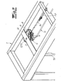
- the exhaust air system 26 is shown schematically in FIG. 4. It is the Outgoing air duct 24 led out of the roof of the building and the exhaust box 30 is connected at the end in the region of the roof to the exhaust duct 24, for example, placed on the roof.
- Fig. 1 shows the building with the smoke protection system initially in the "normal state", that is without a fire in one of the floors.
- Supply air system 20 and exhaust system 26 are out of service.
- the pressure in the entire building corresponds essentially to the atmospheric pressure P0, that is, the pressure difference ⁇ P is about 0 Pa.
- the smoke control flaps 25 are closed.
- both the supply air system 20 and the exhaust air system 26 are put into operation and the smoke compartment 25 assigned to the fire compartment 18 is opened.
- This functional state is indicated in FIG. 2.
- the supply air fan 21 now pumps air in the area of the escape route 19 (staircase). If a predetermined limit pressure ⁇ P + of, for example, 50 Pa is exceeded, then the control valves 23 of the supply air control device 22 automatically open, so that the desired overpressure ⁇ P + of, for example, 50 Pa automatically or automatically adjusts in the region of the escape route 19 , It can also be seen that the fire compartment 18 is separated from the overpressure escape route 19 by a closed door T.
- the exhaust air damper devices 28 are now dimensioned so that upon reaching or exceeding a predetermined limit negative pressure ⁇ P- in the collection box 30, the control valves 29 open automatically inward, so that no unacceptably high negative pressure in the area of the fire area can arise.
- the flap opening pressure essentially corresponds to the maximum channel pressure loss amount ⁇ P k or lies directly above this channel pressure loss amount.
- the channel pressure loss ⁇ P k is, for example 150 Pa, it is convenient to the flap opening pressure and consequently limit negative pressure ⁇ P - adjust the exhaust control valve device 28 to, for example, 160 Pa. Consequently, if a negative pressure of 160 Pa is reached in the region of the collecting tank 30, the control valves 29 open automatically.
- the resulting pressure loss in the collecting box 30 through the open flap surfaces is in the order of magnitude of the maximum duct pressure loss ⁇ P k , so that the open flap position of the connected suction-side channel 24 is no longer flowed through and therefore remains free of pressure loss.
- the supply air system 20 and the exhaust system 26 are in direct contact and in the collecting tank 30 the flap systems are automatically closed as a result of the valve opening pressure being undershot.
- the pressure in the collecting tank increases by the overpressure previously set in the escape route and consequently by, for example, 50 Pa, so that a negative pressure of only 110 Pa is now established so that the flaps close automatically. Now, the planned volume flow through the channel 24 is promoted.
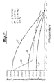
- the negative pressure ⁇ P in the region of the collecting tank 30 is plotted as a function of the delivered volume flow.
- the negative pressure is also defined here as a positive pressure difference, that is, when lowering the internal pressure in the collecting tank against the external pressure of the negative pressure increases.
- the characteristic KL of the vent fan 27 is located.
- the parabola b shows the course during the run-up of the fan 27 with the door closed.
- the negative pressure increases along the pressure loss parabola a until the flap opening pressure is reached, which here corresponds to the duct pressure loss ⁇ P k .
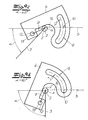
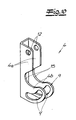
- FIGS. 6 to 11 The detailed structure of both the supply air control flap device 22 and the exhaust air damper devices 28 results from FIGS. 6 to 11.
- a control flap device for a smoke protection differential pressure system with a housing 1, at least one control flap 3 mounted pivotably in the housing about an axis of rotation 2 and at least one closing spring 5 connected on the one hand to the housing 1 and on the other hand via a connection part 4 to the control flap 3.
- the control flap 3 corresponds to either the control flap 23 of the supply air control flap device 22 or the control flap 29 of the exhaust control flap device 28.
- control flap device in the exemplary embodiment as a multi-valve device with a plurality of adjacently arranged control valves 3, 3 ', wherein the control valves 3, 3 'are connected to one another via a connecting linkage 6 and open and close together, and wherein a single common closing spring 5 acts on the plurality of control flaps 3, 3' with the interposition of a single common connecting part 4.
- the closing spring 5 is designed as a tension spring and in the embodiment as a cylindrical coil spring.
- the illustrated damper device can be used in the invention both as supply air damper device and as exhaust air damper device. In the following, this preferred embodiment will be described by way of example as a supply air damper device.
- control flap device illustrated in FIG. 6 separates a (rear) escape route in which an overpressure is to be generated and maintained by a (front) outer space A in which, for example, atmospheric pressure prevails.
- the control valves are not visible in FIGS. 6 and 7. They are arranged in the escape route facing (rear) portion of the housing 1 as shown in FIG. Fig. 8 shows a control valve 3 in the closed position.
- the closing spring 5 generates with its spring force F a closing moment M F holding the control flap 3 in the closed position or in the closed position.
- an overpressure is built in the (rear) escape route, which the escape route free of smoke.
- the control valve 3 pivots to form a flow opening by a predetermined opening angle ⁇ in the opening direction R as soon as an unilaterally acting on the control valve or control valves opening pressure or air pressure P generates a closing torque exceeding opening moment M L.
- the closing moment M F of the closing spring 5 is adjusted such that the opening moment M L exceeds the closing moment M F , in any case at an overpressure ⁇ P of 50 Pa, so that the control flap 3 opens and consequently the overpressure can be reduced by a predetermined amount , As soon as the overpressure has fallen so far that the closing moment again exceeds the opening moment, the control flap 3 automatically closes again.
- the opening direction R is indicated in the figures. With the control flap 3 open and close the other control valves 3 'simultaneously.
- the connecting part which connects the closing spring 5 with the control flap 3
- the connecting part is designed as a connecting lever 4 connected in an articulated manner to the control flap 3. Consequently, a separate connection joint component is provided in the context of the invention, which is connected on the one hand articulated to the closing spring 5 and on the other hand articulated to the control flap 3.
- the connection joint component 4 is consequently both pivotable with respect to the control flap and pivotable with respect to the closing spring.
- FIG. 8 shows that the connection lever 4 is not directly connected to the guide flap, but rather that the connection lever 4 is connected in an articulated manner to a connecting arm 7 connected in a rotationally fixed manner to the control flap 3. This connecting arm 7 is fixed at a fixed angle to the control flap 3.
- closing spring 5 on the one hand and control flap 3 (in the closed position) on the other hand are arranged substantially parallel to each other.
- the closing spring in the closed position at another angle, for example, perpendicular or approximately perpendicular to arrange the control flap.
- the connecting arm is rotatably connected to the control flap.
- the connecting lever 4 has at least one joint recess 12, in which a hinge pin 13 is rotatably mounted. The hinge pin 13 is connected to the control flap 3 or the connecting arm 7.
- the connecting lever 4 has a guide slot 8 and is thus formed as a curve with a curved elongated hole guide 9, wherein in this slot guide 9 is connected to the closing spring 5 end connected guide element in the form of a guide pin 10 hinged and slidably.
- the guide pin 10 is guided roller bearings in the slot guide 9. This is achieved, for example, by (shoulder) ball bearings mounted on both sides of the guide pin 10, which engage in the two elongated holes 9 '.
- the connection lever 4 is L-shaped in the side view and U-shaped in cross-section.
- the slot guide 9 with the two slots 9 ' is arranged. Due to the design of the connection lever 4 as a U-profile, it is expedient if in each case a joint recess 12 and a slot 9 'are provided in the two U-legs, which of course are aligned.
- the closing spring 5 is connected to the closing flap 3 via the connecting lever 4 such that the lever arm a acting on the flap 3 is greater than zero in all flap positions, so that the spring force produces a closing moment greater than zero in all flap positions.
- Lever a and length of the lever arm means in the invention, the vertical Distance of the spring force action line 14 or of the spring force vector from the pivot point or the axis of rotation 2.
- the spring force action line 14 and the control flap 3 and the connecting arm 7 connected thereto are merely indicated.
- the lever arm a is drawn in each case.
- the control flap pivots about the axis of rotation 2. Due to the articulated connection of the connection lever 4 on the one hand, the closing spring 5 and on the other hand the control valve 3, the control flap 3 pulls the connecting lever 4 initially in the direction of the axis of rotation 2, so that the connecting lever 4 comes into abutment against the rotary shaft 2 'at a predetermined critical angle (compare Fig. 9b).
- the lever arm a decreases sharply.
- Fig. 11 shows that the closing moment M F in a first angular range of a flap angle of 0 ° to a flap angle of about 15 ° drops sharply with a high slope and then in a second angle range to the fully open flap angle of 90 ° only slightly decreases with a slight slope. The waste in the second section is consequently (significantly) less than in the first section.
- the closing moment in the second section is constant at least in regions.
- the closing moment M F always has exactly two defined points of intersection with the opening moment M L at 25 Pa.
- the closing moment cuts both the curve B and the curve C defined at high flap opening angles and exactly once. Starting from the full open position at 90 °, the closing moment M F always increases continuously, so that a perfect flap return is ensured.
- the mechanical flap return system or the closing spring can consequently be designed with a substantially constant spring preload, which avoids the additional frictional effects due to increasing spring forces, thereby enabling reliable flap return.
- a guide surface 15 is arranged between the slot guide 9 and the joint recess 12, which is formed in the shape of a curve as it were formed and on which the joint 4 is guided in the course of opening on the rotary shaft 2 '.
- the L-shaped articulated guide lever 4 as it were concentrated around the axis 2, so that the described low moments of inertia occur.
- FIG. 6 shows that the housing 1 in the embodiment as a multi-flap device between the individual juxtaposed control valves 3, 3 'each having a partition wall 16 to form separate flow areas.
- the slot guide 9 extends in an approximately circular arc over an arc length of ⁇ 4 , up to ⁇ 2 , r, where r is the mean radius.
- the biased closing spring 5 is pivotally hinged to the housing 1 and that to a fixed to the housing 1 spring holder 17 which is adjustably or adjustably attached to the housing 1.
- adjustment options or adjustment options which allow to adapt the closing torque of the control valves and consequently also the flap opening pressure within certain limits to the required conditions. This can be useful in particular in the field of exhaust air damper device, since then on site for Example, the possibility exists to optimize the flap opening pressure taking into account the occurring channel pressure loss values.
Abstract
Description
Die Erfindung betrifft eine Rauchschutzanlage für ein Gebäude, welches einen oder mehrere mögliche Brandräume sowie einen oder mehrere über Türen oder dergleichen mit den Brandräumen verbundene Fluchtwege aufweist,
mit
- zumindest einer Zuluft-Anlage, welche zumindest einen die Fluchtwege und gegebenenfalls die Brandräume im Brandfall mit Überdruck beaufschlagenden Zuluft-Ventilator und zumindest eine Zuluft-Regelklappenvorrichtung aufweist, wobei die Zuluft-Regelklappenvorrichtung zumindest eine federbelastete Regelklappe aufweist, die bei Überschreiten eines vorgegebenen Grenzüberdrucks selbsttätig öffnet und bei Unterschreiten des Grenzüberdrucks selbsttätig schließt,
- und zumindest einem Abluft-Kanal, welcher an einen oder mehrere Brandräume unter Zwischenschaltung zumindest jeweils einer Entrauchungsklappe angeschlossen ist und zum Abführen von Rauch aus dem Gebäude herausgeführt ist.
With
- at least one supply air system, which has at least one the escape routes and possibly the fire areas in case of fire pressurized supply air fan and at least one supply air damper device, wherein the supply air damper device has at least one spring-loaded damper that automatically opens when a predetermined limit pressure is exceeded and automatically closes when the pressure drops below the limit,
- and at least one exhaust duct, which is connected to one or more fire chambers with the interposition of at least one smoke control valve and is led out for discharging smoke from the building.
Gebäude meint im Rahmen der Erfindung insbesondere Gebäude mit mehreren Etagen, welche über ein oder mehrere Treppenhäuser miteinander verbunden sind. In derartigen Gebäuden stellen insbesondere die Treppenhäuser und gegebenenfalls sich daran anschließende Flure Fluchtwege bzw. Rettungswege dar. Mögliche Brandräume sind dagegen angrenzende Nutzungseinheiten wie Wohnungen, Büros oder ähnliches. Die Rauchschutzanlage ist als Rauchschutz-Differenzdruckanlage ausgebildet, wobei durch den über die Zuluft-Anlage eingestellten Überdruck im Bereich der Flucht- und Rettungswege eine Rauchfreihaltung im Brandfall gewährleistet ist. Aus Sicherheitsgründen darf der für die Rauchfreihaltung erforderliche Überdruck einen zulässigen Maximalwert (zum Bespiel 50 Pa) nicht überschreiten. Aus diesem Grunde sorgt die Zuluft-Regelklappenvorrichtung für eine selbsttätige Luftabfuhr überschüssiger Luft. Die Regelklappen öffnen bei Erreichen des zulässigen Überdrucks unter Wirkung der skalaren Druckkräfte selbsttätig und die überschüssige Luft wird mit einem Durchström-Druckverlust, der dem geforderten zulässigen Überdruck des Druckraumes entspricht, an die Atmosphäre übergeben, so dass die Regelklappe dann selbsttätig wieder schließt.In the context of the invention, building means in particular buildings with several floors, which are connected to one another via one or more staircases. In such buildings in particular the staircases and possibly adjoining corridors escape routes or escape routes. Possible fire areas, however, are adjacent units such as apartments, offices or the like. The smoke protection system is designed as a smoke protection differential pressure system, with a set by the overpressure system overpressure in the area of escape and rescue routes Smoke free in case of fire is guaranteed. For safety reasons, the overpressure required for keeping smoke free must not exceed a permissible maximum value (eg 50 Pa). For this reason, the supply air damper device provides for automatic air removal of excess air. The control valves open automatically when the permissible overpressure under the effect of the scalar pressure forces and the excess air is transferred to the atmosphere with a flow-through pressure drop corresponding to the required permissible pressure of the pressure chamber, so that the control valve then automatically closes again.
Bei einer bekannten Rauchschutzanlage der eingangs beschriebenen Art können die möglichen Brandräume in den einzelnen Etagen über Entrauchungsklappen an einen gemeinsamen Abluft-Schacht angeschlossen sein. Die Ansteuerung der Anlage erfolgt zum Beispiel über Rauchmelder, die vor jeder Zugangstür im Flur oder der Schleuse der nachgeschalteten Räume außerhalb des geschützten Bereichs angeordnet sind. Bei Rauchdetektierung der Rauchmelder wird die Rauchschutz-Druckanlage, nämlich die Zuluft-Anlage, in Betrieb gesetzt. Dabei stellt jede Etage eine Melder-Linie dar. Die Abströmung des Rauchs im Zuge der Entrauchung kann über den Abluft-schacht erfolgen (vgl.
Der Erfindung liegt die Aufgabe zu Grunde, eine Rauchschutzanlage für ein Gebäude der eingangs beschriebenen Art zu schaffen, welche auf einfache Weise eine zuverlässige und sichere Funktion gewährleistet, ohne dass meteorologische Einflüsse die Sicherheit der Anlage stören können.The invention is based on the object to provide a smoke protection system for a building of the type described above, which is simple Ensuring a reliable and safe function without meteorological influences can disturb the safety of the system.
Zur Lösung dieser Aufgabe lehrt die Erfindung bei einer gattungsgemäßen Rauchschutzanlage, dass an den Abluft-Kanal zumindest eine Abluft-Anlage angeschlossen ist, welche zumindest einen die Abluft-Anlage mit Unterdruck beaufschlagenden Abluft-Ventilator sowie zumindest eine Abluft-Regelklappenvorrichtung aufweist, wobei die Abluft-Regelklappenvorrichtung zumindest eine federbelastete Regelklappe aufweist, die bei Überschreiten eines vorgegebenen Grenzunterdruckes in der Abluft-Anlage selbsttätig öffnet und bei Unterschreiten des Grenzunterdruckes selbsttätig schließt. Die Abluft-Anlage kann dabei zumindest einen an den Abluft-Kanal angeschlossenen Abluftkasten aufweisen, an welchen der Abluft-Ventilator und die Abluft-Regelklappenvorrichtung angeschlossen sind, wobei die Regelklappen im Zuge des Öffnens in Richtung des Innenraums des Abluftkastens schwenken. Unterdruck bzw. Grenzunterdruck sind im Rahmen der Erfindung als positive Druckdifferenzen definiert, das heißt bei Absenkung des Druckes in einem Raum steigt der Unterdruck.To solve this problem, the invention teaches in a generic smoke protection system that at least one exhaust system is connected to the exhaust duct, which has at least one exhaust air system with negative pressure exhaust fan and at least one exhaust damper device, wherein the exhaust air -Regelklappenvorrichtung has at least one spring-loaded control valve, which automatically opens when a predetermined limit negative pressure in the exhaust system and automatically closes when falling below the limit negative pressure. The exhaust air system can have at least one connected to the exhaust air duct exhaust box, to which the exhaust fan and the exhaust control valve device are connected, the control valves pivot in the course of opening in the direction of the interior of the exhaust box. Underpressure or limit negative pressure are defined in the context of the invention as positive pressure differences, that is, when lowering the pressure in a room, the negative pressure increases.
Die Erfindung geht dabei zunächst einmal von der Erkenntnis aus, dass meteorologische Einflüsse auf die Sicherheitsfunktion der Anlage und insbesondere auf das kontinuierliche und zuverlässige Abführen von Rauch dann unterbunden werden können, wenn zur Rauchfreihaltung nicht mit einer natürlichen Abströmung gearbeitet wird, sondern wenn mit einer maschinellen Abluft-Anlage mit Hilfe eines Ventilators aktiv der Rauch aus den Brandräumen über den Abluft-Kanal abgesaugt wird. Der Begriff Ventilator umfasst im Rahmen der Erfindung ganz allgemein saugende und/oder blasende Fördereinrichtungen und folglich auch Pumpen oder dergleichen. Bei Einsatz einer solchen maschinellen Abluft-Anlage mit einem absaugenden Ventilator stellt sich jedoch grundsätzlich das Problem, dass in den an die Fluchtwege angrenzenden Brandräumen durch das Absaugen Differenzdrucke über geschlossene Türen entstehen, welche das Öffnen der Tür zwischen Brandraum und Fluchtweg erheblich erschweren können und somit aus Sicherheitsgründen nicht akzeptabel sind. Denn selbst bei Einsatz einer selbstregelnden Zuluft-Anlage, die dafür sorgt, dass der Überdruck im Bereich der Fluchtwege beispielsweise einen Wert von 50 Pa nicht überschreitet, besteht bei Einsatz einer maschinell saugenden Abluft-Anlage - ohne zusätzliche Maßnahmen - das Problem, dass sich ein Druck im Bereich des Brandraums einstellt, der unterhalb des Atmosphärendrucks liegt, so dass der Differenzdruck dann den zulässigen Maximalwert von 50 Pa überschreitet. Aus diesem Grunde schlägt die Erfindung vor, im Bereich der Abluft-Anlage in Kombination mit einem Abluft-Ventilator eine Abluft-Regelklappenvorrichtung einzusetzen die nun dafür sorgt, dass bei unzulässig niedrigen Drücken im Bereich der Brandräume die federbelastete Regelklappe durch den in der Abluft-Anlage entstehenden Unterdruck selbsttätig öffnet. Erfindungsgemäß wird folglich im Bereich einer geschlossenen Tür zwischen Fluchtweg und Brandraum die zu hohe Druckdifferenz vermieden, so dass über geschlossenen Türen stets nur die positive zulässige Druckdifferenz durch die Zuluft-Anlage anstehen kann. Öffnet sich nun eine solche Tür, sind die maschinelle Zuluft-Anlage und die maschinelle Abluft-Anlage unmittelbar in Kontakt und im Bereich der Abluft-Anlage bzw. im Bereich des Abluftkastens werden infolge Unterschreitung des Klappenöffnungsdruckes die Klappensysteme selbsttätig geschlossen, so dass ein geplanter Volumenstrom durch die Zu- und Abluft-Anlage aus dem Gebäude transportiert wird. Insgesamt gewährleistet die erfindungsgemäße Anlage eine einwandfreie Ableitung des Rauches ohne störende meteorologische Einflüsse und ohne die Gefahr unzulässig hoher Differenzdrücke im Bereich geschlossener Türen zwischen Fluchtwegen und Brandräumen. Dieses gelingt, weil mit einer maschinell absaugenden Abluft-Anlage gearbeitet wird, und zwar in Kombination mit einerseits einer selbstregelnden Differenzdruck-Zuluft-Anlage und andererseits einer selbstregelnden Differenzdruck-Abluft-Anlage, jeweils unter Einsatz von selbsttätigen Regelklappensystemen.The invention is initially based on the recognition that meteorological influences on the safety function of the system and in particular on the continuous and reliable removal of smoke can then be prevented if the smoke is not worked with a natural outflow, but with a machine Exhaust air system with the help of a fan actively the smoke is sucked out of the fire rooms over the exhaust air channel. The term fan includes in the context of the invention quite generally sucking and / or blowing conveyors and consequently also pumps or the like. When using such a mechanical exhaust system with a suction fan, however, there is always the problem that in the on the escape routes adjacent fire areas caused by the suction differential pressure over closed doors, which can significantly complicate the opening of the door between fire and escape route and thus are not acceptable for security reasons. Even with the use of a self-regulating supply air system, which ensures that the overpressure in the area of the escape routes, for example, does not exceed a value of 50 Pa, there is the problem with a machine-sucking exhaust air system - without additional measures - that a Pressure in the range of the fire chamber sets, which is below the atmospheric pressure, so that the differential pressure then exceeds the maximum allowable value of 50 Pa. For this reason, the invention proposes to use an exhaust air damper device in the area of the exhaust air system in combination with an exhaust fan now ensures that at unacceptably low pressures in the field of fire chambers, the spring-loaded damper by the exhaust air system resulting negative pressure automatically opens. According to the invention, the excessively high pressure difference is thus avoided in the area of a closed door between the escape route and the firebox, so that only the positive permissible pressure difference through the supply air system can always be present above closed doors. If such a door now opens, the mechanical supply air system and the mechanical exhaust air system are in direct contact and in the area of the exhaust air system or in the area of the exhaust air box, the flap systems are automatically closed due to the valve opening pressure being undershot, so that a planned volume flow is transported out of the building through the supply and exhaust air system. Overall, the system of the invention ensures proper discharge of the smoke without disturbing meteorological influences and without the risk of unacceptably high differential pressures in the closed doors between escape routes and fire areas. This succeeds because it works with a mechanically extracting exhaust air system, in combination with a self-regulating differential pressure supply system and on the other hand, a self-regulating differential pressure-exhaust system, each using automatic control flap systems.
Der erfindungsgemäße Abluftkasten, an welchen einerseits der Abluft-Ventilator und andererseits die Abluft-Regelklappenvorrichtungen angeschlossen sind, bildet einen Sammelkasten. Dabei ist zweckmäßig, wenn die Abluft-Anlage nicht nur eine, sondern vorzugsweise zwei oder auch mehr als zwei Abluft-Regelklappenvorrichtungen aufweist. Jede einzelne der Abluft-Regelklappenvorrichtungen kann dabei eine oder auch mehrere selbsttätige Regelklappen aufweisen. Bei Einsatz mehrerer Abluft-Regelklappenvorrichtungen besteht die Möglichkeit, diese an unterschiedlichen Seiten bzw. Seitenwänden des Abluftkastens anzuordnen, so dass dann der Einfluss meteorologischer Gegebenheiten weiter reduziert werden kann. Dieses gilt insbesondere, wenn die Abluft-Regelklappenvorrichtungen an gegenüberliegenden Seiten des Abluftkastens angeordnet werden. Es kann bei einem Abluftkasten mit rechteckigem Querschnitt auch besonders zweckmäßig sein, mit vier Abluft-Regelklappenvorrichtungen zu arbeiten, welche jeweils einer Seitenwand zugeordnet sind. Im Übrigen ist es zweckmäßig, wenn der Abluft-Kanal, zum Beispiel in der Ausführungsform als L90-Schacht, aus dem Dach des Gebäudes herausgeführt ist und der Abluftkasten folglich endseitig im Bereich des Daches an den Abluft-Kanal angeschlossen ist.The exhaust box according to the invention, to which on the one hand the exhaust fan and on the other hand, the exhaust air control valve devices are connected, forms a collecting box. It is expedient if the exhaust air system has not only one, but preferably two or even more than two exhaust air damper devices. Each of the exhaust air damper devices may have one or more automatic control valves. When using multiple exhaust air damper devices, it is possible to arrange them on different sides or side walls of the exhaust box, so that then the influence of meteorological conditions can be further reduced. This is particularly true when the exhaust air damper devices are placed on opposite sides of the exhaust box. It may also be particularly useful in an exhaust box with a rectangular cross-section to work with four exhaust air damper devices which are each associated with a side wall. Incidentally, it is expedient if the exhaust duct, for example in the embodiment as L90 shaft, led out of the roof of the building and the exhaust box is therefore connected at the end in the region of the roof to the exhaust air duct.
Nach einem weiteren Vorschlag der Erfindung, dem besondere Bedeutung zukommt, ist vorgesehen, dass der dem Grenzunterdruck entsprechende Klappen-Öffnungsdruck der Regelklappe(n) der Abluft-Regelklappenvorrichtung in etwa dem (maximalen) Kanaldruckverlust des Abluft-Kanals bei einem vorgegebenen Volumenstrom entspricht oder (geringfügig) größer ist. Der Kanaldruckverlust ist im Rahmen der Erfindung als positive Druckdifferenz definiert. Der Klappenöffnungsdruck, bei dem die Regelklappen wegen des geringen Innendrucks im Sammelkasten nach innen schwenken, ist hier ebenfalls als positive Druckdifferenz definiert. Dabei geht die Erfindung von der Erkenntnis aus, dass das Ableiten eines vorgegebenen Volumenstroms aus den Brandräumen über den Abluft-Kanal in den Bereich der Abluft-Anlage mit einem ganz bestimmten Druckverlust im Abluft-Kanal verbunden ist. Diese Druckverluste können insbesondere bei Gebäuden mit einer Vielzahl von Etagen eine Größenordnung erreichen, die dem Überdruck von beispielsweise 50 Pa im Bereich der Fluchtwege entspricht oder auch deutlich größer ist. Dieser saugseitige Kanaldruckverlust wird im Rahmen der Erfindung nun dadurch kompensiert, dass der Klappenöffnungsdruck der Abluft-Regelklappenvorrichtungen so dimensioniert wird, dass er dem maximalen Kanaldruckverlust entspricht oder geringfügig größer ist. Auf diese Weise wird auch unter Berücksichtung der Kanaldruckverluste gewährleistet, dass trotz der erheblichen Unterdrücke im Bereich des Sammelkastens im Bereich der Brandräume stets ein solcher Druck eingestellt ist, dass über geschlossenen Türen keine unzulässig hohen Druckdifferenzen entstehen. So stellt sich im Bereich des Abluftkastens nach Hochlaufen des Ventilators bei geschlossener Tür ein Unterdruck ein, welcher dem Kanaldruckverlust entspricht. In diesem Moment öffnen die Regelklappen und der Ventilator saugt gleichsam über die geöffneten Regelklappen unmittelbar aus der Atmosphäre. Die durch die geöffneten Klappenflächen entstehenden Druckverluste im Sammelkasten liegen in der Größenordnung des maximalen Kanaldruckverlustes, so dass für die geöffnete Klappenstellung der angeschlossene saugseitige Kanal nicht durchströmt wird und demzufolge druckverlustfrei bleibt. Der Abzugs-Ventilator erfährt in dieser Funktionsstellung lediglich unwesentliche Arbeitspunktverschiebungen auf der Kennlinie. Wird nun eine Tür zwischen Fluchtweg und Brandraum geöffnet, so erhöht sich der Druck im Abluftkasten um den ursprünglich im Fluchtweg eingestellten positiven Überdruck von zum Beispiel 50 Pa, so dass der Unterdruck im Abluftkasten sinkt und folglich der Klappenöffnungsdruck unterschritten wird, so dass die Klappen selbsttätig schließen. Über den Abluft-Kanal wird dann der geplante Volumenstrom gefördert.According to a further proposal of the invention, which has special significance, it is provided that the flap opening pressure corresponding to the limit negative pressure of the control valve (s) of the exhaust air damper device corresponds approximately to the (maximum) duct pressure loss of the exhaust air duct at a given volume flow or ( slightly larger). The channel pressure loss is defined in the context of the invention as a positive pressure difference. The flap opening pressure, at which the control valves pivot inwards because of the low internal pressure in the collecting box, is here also defined as a positive pressure difference. The invention is based on the recognition that the discharge of a predetermined volume flow from the fire chambers via the exhaust air duct in the region of the exhaust air system is connected to a very specific pressure drop in the exhaust duct. These pressure losses can reach an order of magnitude, in particular in buildings with a plurality of floors, which corresponds to the overpressure of, for example, 50 Pa in the area of escape routes or is also significantly greater. This suction-side duct pressure loss is compensated within the scope of the invention in that the flap opening pressure of the exhaust air damper devices is dimensioned so that it corresponds to the maximum channel pressure loss or is slightly larger. In this way, taking account of the duct pressure losses, it is ensured that, despite the considerable negative pressures in the area of the collecting tank in the area of the fire areas, such a pressure is always set that no unacceptably high pressure differences arise over closed doors. Thus, in the area of the exhaust air box, after the fan has started up when the door is closed, a negative pressure occurs which corresponds to the duct pressure loss. At this moment open the control valves and the fan sucks as it were over the open control valves directly from the atmosphere. The resulting pressure losses through the open flap surfaces in the collecting tank are in the order of the maximum channel pressure loss, so that for the open flap position of the connected suction-side channel is not flowed through and therefore remains free of pressure loss. The vent fan learns in this functional position only insignificant operating point shifts on the curve. If a door is now opened between the escape route and the fire compartment, the pressure in the exhaust box increases by the positive overpressure originally set in the escape route of, for example, 50 Pa, so that the negative pressure in the exhaust box drops and, consequently, the flap opening pressure falls below, so that the flaps automatically shut down. The planned volume flow is then conveyed via the exhaust air duct.
Wie erläutert kommt im Rahmen der Erfindung sowohl den Zuluft-Regelklappenvorrichtungen als auch den Abluft-Regelklappenvorrichtungen besondere Bedeutung zu. Insofern können grundsätzlich herkömmliche Regelklappenvorrichtungen mit federbelasteten selbsttätigen Regelklappen zum Einsatz kommen. In besonders bevorzugter Ausführungsform der Erfindung werden jedoch Regelklappenvorrichtungen gemäß den Patentansprüchen 7 bis 12 verwendet. Weitere Einzelheiten dazu sind Gegenstand der Figurenbeschreibung.As explained, in the context of the invention, both the supply air control flap devices and the exhaust air flap valve devices are of particular importance. In this respect, conventional control valve devices with spring-loaded automatic control valves can be used in principle. However, in a particularly preferred embodiment of the invention, damper devices according to
Ferner ist Gegenstand der Erfindung ein Verfahren zum Abführen von Rauch aus Brandräumen eines Gebäudes und zur Rauchfreihaltung von Fluchtwegen des Gebäudes mit einer Rauchschutzanlage der beschriebenen Art, wobei im Brandfall mit der Zuluft-Anlage in den Fluchtwegen ein Überdruck eingerichtet wird, welcher einen vorgegebenen Grenz-Überdruck nicht überschreitet, wobei mit der Abluft-Anlage Rauch aus einem über eine geschlossene Tür von dem Fluchtweg getrennten Brandraum derart abgeführt wird, dass in dem Brandraum ein vorgegebener Minimaldruck nicht unterschritten wird, so dass die Druckdifferenz zwischen Fluchtweg und Brandraum über die geschlossene Tür den vorgegebenen Grenz-Überdruck nicht überschreitet. Die Einhaltung des zugelassenen Minimaldrucks, zum Beispiel Atmosphärendrucks, im Bereich des Brandraumes erfolgt durch selbsttätige Einstellung eines vorgegebenen Grenzunterdrucks in der Abzugsanlage, zum Beispiel in einem Sammelkasten, und zwar bevorzugt unter Berücksichtigung des maximal möglichen Kanaldruckverlustes im Abzugskanal zwischen Brandraum und Sammelkasten.Furthermore, the subject matter of the invention is a method for evacuating smoke from fire compartments of a building and for keeping smoke out of escape routes of the building with a smoke protection system of the type described, wherein in the case of fire with the supply air system in the escape routes an overpressure is established, which a predetermined limit Overpressure does not exceed, with the exhaust air system smoke is discharged from a closed door from the escape route fire room such that in the fire room a predetermined minimum pressure is not exceeded, so that the pressure difference between the escape route and fire room on the closed door does not exceed the specified limit overpressure. Adherence to the permitted minimum pressure, for example atmospheric pressure, in the area of the fire compartment is achieved by automatically setting a predetermined limit vacuum in the exhaust system, for example in a collecting box, preferably taking into account the maximum possible pressure loss in the duct between the fire compartment and collecting tank.
Im Folgenden wird die Erfindung anhand einer lediglich ein Ausführungsbeispiel darstellenden Zeichnung näher erläutert. Es zeigen
- Fig. 1
- eine erfindungsgemäße Rauchschutzanlage in einem mehrgeschossigen Gebäude in schematischer Ansicht,
- Fig. 2
- den Gegenstand nach Fig. 1 im Brandfall bei geschlossener Tür zwischen Fluchtweg und Brandraum,
- Fig. 3
- den Gegenstand nach Fig. 2 bei geöffneter Tür zwischen Fluchtweg und Brandraum,
- Fig. 4
- einen Ausschnitt aus dem Gegenstand nach Fig. 2,
- Fig. 5
- ein Arbeitsdiagramm des Abzugs-Ventilators im Betrieb der Anlage,
- Fig. 6
- eine bevorzugt eingesetzte Regelklappenvorrichtung als Mehrklappenvorrichtung in perspektivischer Ansicht,
- Fig. 7
- einen Ausschnitt aus dem Gegenstand nach Fig. 6,
- Fig. 8
- eine schematische Draufsicht auf den Gegenstand nach Fig. 7,
- Fig. 9a-d
- schematisch und ausschnittsweise den Gegenstand nach Fig. 8 in unterschiedlichen Funktionsstellungen,
- Fig. 10
- den Anschlusshebel einer erfindungsgemäßen Regelklappenvorrichtung in perspektivischer Ansicht und
- Fig. 11
- den Verlauf der öffnenden Momente und des schließenden Moments in Abhängigkeit vom Regelklappenwinkel.
- Fig. 1
- a smoke protection system according to the invention in a multi-storey building in a schematic view,
- Fig. 2
- 1 in case of fire with the door closed between the escape route and the fire compartment,
- Fig. 3
- the object according to FIG. 2 with the door open between the escape route and the fire compartment,
- Fig. 4
- a detail of the article of FIG. 2,
- Fig. 5
- a working diagram of the extraction fan during operation of the system,
- Fig. 6
- a preferably used control flap device as a multi-flap device in a perspective view,
- Fig. 7
- a detail of the article of FIG. 6,
- Fig. 8
- a schematic plan view of the article of FIG. 7,
- Fig. 9a-d
- schematically and partially the article of FIG. 8 in different functional positions,
- Fig. 10
- the connection lever of a control valve device according to the invention in a perspective view and
- Fig. 11
- the course of the opening moments and the closing moment depending on the damper angle.
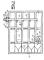
In den Fig. 1 bis 3 ist schematisch ein mehrgeschossiges Gebäude mit einer erfindungsgemäßen Rauchschutzanlage dargestellt. Das Gebäude weist eine Mehrzahl von Etagen mit mehreren möglichen Brandräumen 18 sowie einem Fluchtweg 19 auf, wobei die Brandräume 18 über Türen T mit dem Fluchtweg 19 verbunden sind. Bei dem Fluchtweg 19 handelt es sich hier insbesondere um ein Treppenhaus. In der unteren Etage ist eine Zuluft-Anlage 20 angeordnet, welche einen Zuluft-Ventilator 21 aufweist, der im Brandfall die Fluchtwege 19 und - bei einer eventuell geöffneten Tür T - auch einen möglichen Brandraum 18 mit Überdruck beaufschlagt. Ferner weist die Zuluft-Anlage 20 eine Zuluft-Regelklappenvorrichtung 22 auf, welche zumindest eine federbelastete Regelklappe 23 aufweist, die bei Überschreiten eines vorgegebenen Grenzüberdrucks Δ P+ selbsttätig nach außen öffnet und bei Unterschreiten des Grenzüberdrucks Δ P+ selbsttätig schließt. Ferner ist ein Abluft-Kanal 24 vorgesehen, welcher an die Brandräume 18 unter Zwischenschaltung zumindest jeweils einer Entrauchungsklappe 25 angeschlossen ist und zum Abführen von Rauch aus dem Gebäude herausgeführt ist. An diesen Abluft-Kanal 24 ist eine Abluft-Anlage 26 angeschlossen, welche einen die Abluft-Anlage 26 mit Unterdruck beaufschlagenden Abluft-Ventilator 27 sowie mehrere Abluft-Regelklappenvorrichtungen 28 aufweist. Die Abluft-Regelklappenvorrichtungen 28 weisen jeweils zumindest eine federbelastete Regelklappe 29 auf, die bei Überschreiten eines vorgegebenen Grenzunterdruckes Δ P- in der Abluft-Anlage 26 selbsttätig öffnet und bei Unterschreiten des Grenzunterdruckes Δ P- selbsttätig schließt. Dabei weist die Abluft-Anlage 26 einen an den Abluft-Kanal 24 angeschlossenen Abluftkasten 30 auf, an welchen einerseits der Abluft-Ventilator 27 und andererseits die beiden Abluft-Regelklappenvorrichtungen 28 angeschlossen sind, wobei die Regelklappen 29 im Zuge des Öffnens in Richtung des Innenraumes des Abluftkastens 30 schwenken. Im Ausführungsbeispiel sind die beiden Abluft-Regelklappenvorrichtungen 28 an unterschiedlichen Seiten des Abluftkastens 30 angeordnet, nämlich an gegenüberliegenden Seiten. Die Abluft-Anlage 26 ist schematisch in Fig. 4 dargestellt. Dabei ist der Abluft-Kanal 24 aus dem Dach des Gebäudes herausgeführt und der Abluftkasten 30 ist endseitig im Bereich des Daches an den Abluft-Kanal 24 angeschlossen, zum Beispiel auf das Dach aufgesetzt.A multi-storey building with a smoke protection system according to the invention is shown schematically in FIGS. The building has a plurality of floors with several
Die Funktionsweise der erfindungsgemäßen Rauchschutzanlage ergibt sich insbesondere aus einer vergleichenden Betrachtung der Fig. 1 bis 3.The operation of the smoke protection system according to the invention results in particular from a comparative consideration of FIGS. 1 to 3.
Fig. 1 zeigt das Gebäude mit der Rauchschutzanlage zunächst im "Normalzustand", das heißt ohne einen Brand in einer der Etagen. Zuluft-Anlage 20 und Abluft-Anlage 26 sind außer Betrieb. Der Druck im gesamten Gebäude entspricht im Wesentlichen dem Atmosphärendruck P0, das heißt die Druckdifferenz Δ P beträgt ca. 0 Pa. Die Entrauchungsklappen 25 sind geschlossen.Fig. 1 shows the building with the smoke protection system initially in the "normal state", that is without a fire in one of the floors.
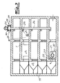
Wird nun ein Brand in einer der Etagen über zum Beispiel einen nicht dargestellten Rauchmelder detektiert, so werden sowohl die Zuluft-Anlage 20 als auch die Abluft-Anlage 26 in Betrieb genommen und die dem Brandraum 18 zugeordnete Entrauchungsklappe 25 wird geöffnet. Dieser Funktionszustand ist in Fig. 2 angedeutet. Der Zuluft-Ventilator 21 pumpt nun Luft in den Bereich des Fluchtweges 19 (Treppenhaus). Wird dabei ein vorgegebener Grenzüberdruck Δ P+ von zum Beispiel 50 Pa überschritten, so öffnen die Regelklappen 23 der Zuluft-Regelklappenvorrichtung 22 selbsttätig, so dass sich der gewünschte Überdruck Δ P+ von beispielsweise 50 Pa selbsttätig bzw. automatisch im Bereich des Fluchtweges 19 einstellt. Ferner ist erkennbar, dass der Brandraum 18 über eine geschlossene Tür T von dem unter Überdruck stehenden Fluchtweg 19 getrennt ist. Da nicht nur die Zuluft-Anlage 20 sondern auch die Abluft-Anlage 26 im Brandfall hochgefahren wird, wird nun über den Abluft-Ventilator 27 der entstehende Rauch aus dem Brandraum 18 abgesaugt, und zwar durch die geöffnete Entrauchungsklappe 25 und den Abluft-Kanal 24. Die Abluft-Regelklappenvorrichtungen 28 im Bereich des Abluftkastens 30 sorgen nun dafür, dass im Bereich des Brandraumes 18 kein unzulässig hoher Unterdruck entsteht, da dieser bei geschlossener Tür T das Öffnen dieser Tür erschweren würde. Es ist folglich von besonderer Bedeutung, dass im Bereich geschlossener Türen T zwischen Brandraum 18 einerseits und Fluchtweg 19 andererseits keine unzulässig hohen Differenzdrucke auftreten. Aufgrund des Kanaldruckverlustes Δ Pk im Abluft-Kanal 24 entsteht im Zuge des Absaugens mit dem Abluft-Ventilator 27 im Bereich des Sammelkastens 30 ein Unterdruck. Die Abluft-Regelklappenvorrichtungen 28 sind nun so dimensioniert, dass bei Erreichen bzw. Überschreiten eines vorgegebenen Grenzunterdruckes Δ P- im Sammelkasten 30 die Regelklappen 29 selbsttätig nach innen öffnen, so dass kein unzulässig hoher Unterdruck im Bereich des Brandraumes entstehen kann. Der Klappenöffnungsdruck entspricht dabei im Wesentlichen dem maximalen Kanaldruckverlustbetrag Δ Pk bzw. liegt unmittelbar oberhalb dieses Kanaldruckverlustbetrages. Beträgt der Kanaldruckverlust Δ Pk beispielsweise 150 Pa, so ist es zweckmäßig, den Klappen-Öffnungsdruck und folglich Grenzunterdruck Δ P- der Abluft-Regelklappenvorrichtung 28 auf zum Beispiel 160 Pa einzustellen. Wird folglich im Bereich des Sammelkastens 30 ein Unterdruck von 160 Pa erreicht, so öffnen die Regelklappen 29 selbsttätig. Der durch die geöffneten Klappenflächen entstehende Druckverlust im Sammelkasten 30 liegt in der Größenordnung des maximalen Kanaldruckverlustes Δ Pk, so dass für die geöffnete Klappenstellung der angeschlossene saugseitige Kanal 24 nicht mehr durchströmt wird und demzufolge druckverlustfrei bleibt.If a fire is now detected in one of the floors via, for example, a smoke detector, not shown, then both the
Wird nun die Tür T zwischen Brandraum 18 und Fluchtraum 19 so wie in Fig. 3 angedeutet geöffnet, sind die Zuluft-Anlage 20 und die Abluft-Anlage 26 unmittelbar in Kontakt und im Sammelkasten 30 werden infolge der Unterschreitung des Klappenöffnungsdruckes die Klappensysteme selbsttätig geschlossen. Der Druck im Sammelkasten steigt um den zuvor im Fluchtweg eingestellten Überdruck und folglich um beispielsweise 50 Pa, so dass sich ein Unterdruck von nun nur noch 110 Pa einstellt, so dass die Klappen selbsttätig schließen. Nun wird der geplante Volumenstrom über den Kanal 24 gefördert.If the door T between the
Durch die Dimensionierung des Systems ist dabei gewährleistet, dass - wegen der Kanaldruckverluste - die Klappen nicht ohne weiteres wieder öffnen. Dieses geschieht erst, wenn die beschriebene Tür wieder geschlossen wird, so dass dann wieder eine Druckdifferenz über die geschlossene Tür aufgebaut werden kann.By sizing the system is ensured that - because of the channel pressure losses - the flaps do not open again easily. This happens only when the described door is closed again, so that then again a pressure difference across the closed door can be established.
Die Funktionsweise wird auch anhand des Arbeitsdiagramms gemäß Fig. 5 deutlich. Dort ist der Unterdruck Δ P im Bereich des Sammelkastens 30 als Funktion des geförderten Volumenstroms aufgetragen. Der Unterdruck ist auch hier als positive Druckdifferenz definiert, das heißt bei Absenkung des Innendrucks im Sammelkasten gegenüber dem Außendruck steigt der Unterdruck. Dabei ist die Kennlinie KL des Abzugs-Ventilators 27 eingezeichnet. Die Parabel b zeigt den Verlauf während des Hochlaufens des Ventilators 27 bei geschlossener Tür. Der Unterdruck steigt entlang der Druckverlustparabel a an, bis der Klappenöffnungsdruck erreicht ist, der hier dem Kanaldruckverlust Δ Pk entspricht. Sobald dieser Klappenöffnungsdruck erreicht ist, öffnen die Klappen schlagartig, so dass der Arbeitspunkt des Ventilators bei geschlossener Tür und geöffneten Klappen auf der Kennlinie erreicht wird. Wird nun die in den Figuren dargestellte Tür T geöffnet, so erhöht sich der Druck im Sammelkasten 30 um den ursprünglich im Bereich des Fluchtweges eingestellten Überdruck Δ P+ = 50 Pa. Dieses führt zu einer Absenkung des Unterdrucks im Bereich des Sammelkastens um genau diesen Differenzbetrag. Nun wird über den Abzugskanal 30 ein vorgegebener Volumenstrom gefördert, so dass der Druck im Sammelkasten 30 sinkt und folglich der Differenzdruck wieder steigt, bis der Arbeitspunkt der Kennlinie bei geöffneter Tür T und geschlossenen Klappen erreicht ist.The operation is also clear from the working diagram of FIG. 5. There, the negative pressure Δ P in the region of the collecting
Der detaillierte Aufbau sowohl der Zuluft-Regelklappenvorrichtung 22 als auch der Abluft-Regelklappenvorrichtungen 28 ergibt sich aus den Fig. 6 bis 11. Dort ist eine solche Regelklappenvorrichtung für eine Rauchschutz-Differenzdruckanlage mit einem Gehäuse 1, zumindest einer um eine Drehachse 2 schwenkbar in dem Gehäuse gelagerten Regelklappe 3 und zumindest einer einerseits an das Gehäuse 1 und andererseits über ein Anschlussteil 4 an die Regelklappe 3 angeschlossenen Schließfeder 5 dargestellt. Die Regelklappe 3 entspricht hier entweder der Regelklappe 23 der Zuluft-Regelklappenvorrichtung 22 oder der Regelklappe 29 der Abluft-Regelklappenvorrichtung 28. Gemäß Fig. 6 ist die Regelklappenvorrichtung im Ausführungsbeispiel als Mehrklappenvorrichtung mit einer Mehrzahl nebeneinander angeordneter Regelklappen 3, 3' ausgebildet, wobei die Regelklappen 3, 3' über ein Verbindungsgestänge 6 miteinander verbunden sind und gemeinsam öffnen und schließen, und wobei auf die mehreren Regelklappen 3, 3' eine einzige gemeinsame Schließfeder 5 unter Zwischenschaltung eines einzigen gemeinsamen Anschlussteils 4 wirkt. Die Schließfeder 5 ist als Zugfeder und im Ausführungsbeispiel als zylindrische Schraubenfeder ausgebildet. Die dargestellte Regelklappenvorrichtung kann im Rahmen der Erfindung sowohl als Zuluft-Regelklappenvorrichtung als auch als Abluft-Regelklappenvorrichtung eingesetzt werden. Im Folgenden soll diese bevorzugte Ausführungsform beispielhaft als Zuluft-Regelklappenvorrichtung beschrieben werden.The detailed structure of both the supply air
Die in Fig. 6 dargestellte Regelklappenvorrichtung trennt im Rahmen der Rauchschutz-Differenzdruckanlage einen (hinteren) Fluchtweg, in welchem ein Überdruck erzeugt und aufrechterhalten werden soll von einem (vorderen) Außenraum A, in dem beispielsweise Atmosphärendruck herrscht. Die Regelklappen sind in Fig. 6 und 7 nicht erkennbar. Sie sind gemäß Fig. 8 in dem dem Fluchtweg zugewandten (hinteren) Bereich des Gehäuses 1 angeordnet. Fig. 8 zeigt dabei eine Regelklappe 3 in Schließstellung. Die Schließfeder 5 erzeugt mit ihrer Federkraft F ein die Regelklappe 3 in Schließstellung haltendes bzw. in Schließstellung überführendes Schließmoment MF. Über den hier nicht dargestellten Ventilator, welcher ebenfalls Bestandteil der Differenzdruckanlage ist, wird in dem (hinteren) Fluchtweg ein Überdruck aufgebaut, welcher den Fluchtweg von Rauch freihält. Die Regelklappe 3 schwenkt unter Bildung einer Durchströmöffnung um einen vorgegebenen Öffnungswinkel α in Öffnungsrichtung R, sobald ein einseitig auf die Regelklappe bzw. Regelklappen wirkender Öffnungsdruck bzw. Luftdruck P ein das Schließmoment übersteigendes Öffnungsmoment ML erzeugt. Im Ausführungsbeispiel ist das Schließmoment MF der Schließfeder 5 so eingestellt, dass das Öffnungsmoment ML jedenfalls bei einem Überdruck Δ P von 50 Pa das Schließmoment MF übersteigt, so dass die Regelklappe 3 öffnet und folglich der Überdruck um ein vorgegebenes Maß abgebaut werden kann. Sobald der Überdruck soweit abgesunken ist, dass das Schließmoment das Öffnungsmoment wieder übersteigt, schließt die Regelklappe 3 wieder selbsttätig. Die Öffnungsrichtung R ist in den Figuren angedeutet. Mit der Regelklappe 3 öffnen und schließen die übrigen Regelklappen 3' simultan.In the context of the smoke protection differential pressure system, the control flap device illustrated in FIG. 6 separates a (rear) escape route in which an overpressure is to be generated and maintained by a (front) outer space A in which, for example, atmospheric pressure prevails. The control valves are not visible in FIGS. 6 and 7. They are arranged in the escape route facing (rear) portion of the
Im Ausführungsbeispiel ist das Anschlussteil, welches die Schließfeder 5 mit der Regelklappe 3 verbindet, als gelenkig an die Regelklappe 3 angeschlossener Anschlusshebel 4 ausgebildet. Folglich wird im Rahmen der Erfindung ein separates Anschlussgelenkbauteil zur Verfügung gestellt, welches einerseits gelenkig an die Schließfeder 5 und andererseits gelenkig an die Regelklappe 3 angeschlossen ist. Das Anschlussgelenkbauteil 4 ist folglich sowohl schwenkbar gegenüber der Regelklappe als auch schwenkbar gegenüber der Schließfeder. Dabei zeigt Fig. 8, dass der Anschlusshebel 4 nicht unmittelbar an die Führungsklappe angeschlossen ist, sondern dass der Anschlusshebel 4 gelenkig an einen drehfest mit der Regelklappe 3 verbundenen Verbindungsarm 7 angeschlossen ist. Dieser Verbindungsarm 7 ist unter einem festen Winkel an der Regelklappe 3 befestigt. Die Anordnung ist im Übrigen so getroffen, dass Schließfeder 5 einerseits und Regelklappe 3 (in Schließstellung) andererseits im Wesentlichen parallel zueinander angeordnet sind. Es besteht aber grundsätzlich auch die Möglichkeit, die Schließfeder in Schließstellung in anderem Winkel, zum Beispiel senkrecht bzw. in etwa senkrecht zur Regelklappe anzuordnen. Dann ist es lediglich erforderlich, den Verbindungsarm unter anderem Winkel an die Regelklappe anzuschließen. Stets ist der Verbindungsarm jedoch drehfest mit der Regelklappe verbunden. Jedenfalls weist der Anschlusshebel 4 zumindest eine Gelenkausnehmung 12 auf, in welcher ein Gelenkstift 13 drehbar gelagert ist. Der Gelenkstift 13 ist an die Regelklappe 3 oder den Verbindungsarm 7 angeschlossen.In the exemplary embodiment, the connecting part, which connects the
Der Anschlusshebel 4 weist eine Führungskulisse 8 auf und ist folglich als Kurvenzug mit einer kurvenförmigen Langlochführung 9 ausgebildet, wobei in dieser Langlochführung 9 ein an die Schließfeder 5 endseitig angeschlossenes Führungselement in Form eines Führungszapfens 10 gelenkig und verschiebbar geführt ist. Der Führungszapfen 10 ist dabei wälzgelagert in der Langlochführung 9 geführt. Dieses gelingt zum Beispiel durch beidseitig auf den Führungszapfen 10 aufgesetzte (Schulter-)Kugellager, welche in die beiden Langlöcher 9' eingreifen. Im Übrigen ist in den Figuren erkennbar, dass der Anschlusshebel 4 in der Seitenansicht L-förmig und im Querschnitt U-förmig ausgebildet ist. In der Seitenansicht ist in dem einem L-Schenkel 4a eine Gelenkausnehmung 12 zur gelenkigen Anlenkung des Verbindungsarms 7 und in dem anderen L-Schenkel 4b die Langlochführung 9 mit den beiden Langlöchern 9' angeordnet. Durch die Ausbildung des Anschlusshebels 4 als U-Profil ist es zweckmäßig, wenn in den beiden U-Schenkeln jeweils eine Gelenkausnehmung 12 und ein Langloch 9' vorgesehen sind, wobei diese selbstverständlich fluchten.The connecting
Erfindungsgemäß ist die Schließfeder 5 über den Anschlusshebel 4 derart an die Schließklappe 3 angeschlossen, dass der auf die Klappe 3 wirkende Hebelarm a in allen Klappenstellungen größer Null ist, so dass die Federkraft in allen Klappenstellungen ein Schließmoment größer Null erzeugt. Hebelarm a bzw. Länge des Hebelarms meint im Rahmen der Erfindung den senkrechten Abstand der Federkraftwirkungslinie 14 bzw. des Federkraftvektors von dem Drehpunkt bzw. der Drehachse 2.According to the invention, the
Die Funktionsweise der Regelklappenvorrichtung wird im Folgenden anhand der Fig. 9a bis 9d unter gleichzeitiger Berücksichtigung der Momentenverläufe gemäß Fig. 11 erläutert. Fig. 9a bis 9d zeigen schematisch den Anschlusshebel 4 in unterschiedlichen Funktionsstellungen bei einem Öffnungswinkel von α = 0°, α = 15°, α = 45° sowie α = 90°. Die Federkraftwirkungslinie 14 sowie die Regelklappe 3 und der daran angeschlossene Verbindungsarm 7 sind lediglich angedeutet. Ferner ist jeweils der Hebelarm a eingezeichnet.The mode of operation of the control flap device will be explained below with reference to FIGS. 9a to 9d with simultaneous consideration of the torque curves according to FIG. 9a to 9d show schematically the
Gemäß Fig. 9a ist der Anschlusshebel 4 in Schließstellung (α = 0°) der Regelklappe 3 zunächst von der Drehachse 2 bzw. Drehwelle 2' beabstandet und folglich berührungsfrei angeordnet. Im Zuge des Öffnens der Regelklappe 3 bei einem vorgegebenen Öffnungsdruck schwenkt die Regelklappe um die Drehachse 2. Durch die gelenkige Anbindung des Anschlusshebels 4 an einerseits die Schließfeder 5 und andererseits die Regelklappe 3 zieht die Regelklappe 3 den Anschlusshebel 4 zunächst in Richtung der Drehachse 2, so dass der Anschlusshebel 4 bei einem vorgegebenen Grenzwinkel gegen die Drehwelle 2' zur Anlage kommt (vgl. Fig. 9b). Der Hebelarm a nimmt stark ab. Sofern die Regelklappe 3 anschließend über diesen Grenzwinkel hinaus weiter geöffnet wird, bleibt der Anschlusshebel 4 in Anlage mit der Drehwelle 2', so dass der Anschlusshebel 4 reibungsfrei mit der Drehwelle 2' rotiert. Der gemäß Fig. 9a bei α = 0° in der oberen Endstellung angeordnete Führungszapfen 10 wandert in der Langlochführung 9 bis er bei vollständig geöffneter Regelklappe 3 in die gegenüberliegende untere Endstellung gelangt. Eine vergleichende Betrachtung der Fig. 9a bis 9d zeigt, dass selbst bei hohen Öffnungswinkeln stets ein definierter Resthebelarm a verbleibt.According to FIG. 9a, in the closed position (α = 0 °) of the
Dieses spiegelt sich in den Momentenverläufen gemäß Fig. 11 wieder. In Fig. 11 sind zunächst einmal als Kurven A, B, C die vom Klappenwinkel α abhängigen Öffnungsmomente ML für einen Überdruck ΔP von 12,5 Pa, 25 Pa sowie 50 Pa dargestellt. Ferner ist als Kurve D das von der Schließfeder 5 erzeugte Schließmoment MF ebenfalls in Abhängigkeit vom Klappenwinkel α aufgezeichnet. Es ist zunächst einmal erkennbar, dass das von der Schließfeder 5 erzeugte Schließmoment MF von der Schließstellung (α = 0°) bis in die vollständige Offenstellung (α = 90°) kontinuierlich abnimmt und stets größer Null ist. Durch die bereits erläuterte Resthebelarmlänge a größer Null bei sämtlichen Öffnungswinkeln α wird folglich gewährleistet, dass bei im Wesentlichen konstanter Federkraft stets ein ausreichendes Schließmoment und folglich Rückholmoment verbleibt. Dieses gelingt im Wesentlichen durch die gelenkige Anbindung der Regelklappe 3 unter Zwischenschaltung des gleichsam freibeweglichen Anschlussgelenkes 4 an die Schließfeder 5. So zeigt Fig. 11, dass das Schließmoment MF in einem ersten Winkelbereich von einem Klappenwinkel von 0° bis zu einem Klappenwinkel von etwa 15° mit hoher Steigung stark abfällt und dann in einem zweiten Winkelbereich bis zum vollständig geöffneten Klappenwinkel von 90° lediglich mit geringer Steigung schwach abnimmt. Der Abfall in dem zweiten Abschnitt ist folglich (deutlich) geringer als in dem ersten Abschnitt. Es werden im Übrigen auch Ausführungsformen umfasst, bei denen das Schließmoment in dem zweiten Abschnitt zumindest bereichsweise konstant ist. Stets soll jedoch gewährleistet sein, dass das Schließmoment bei steigendem Öffnungswinkel nicht wieder zunimmt. Dabei macht Fig. 11 deutlich, dass das Schließmoment MF stets exakt zwei definierte Schnittpunkte mit dem Öffnungsmoment ML bei 25 Pa aufweist. Dabei schneidet das Schließmoment (Kurve D) sowohl die Kurve B als auch die Kurve C bei hohen Klappenöffnungswinkeln definiert und exakt einmal. Ausgehend von der vollständigen Offenstellung bei 90° wächst das Schließmoment MF stets kontinuierlich an, so dass eine einwandfreie Klappenrückführung gewährleistet ist.This is reflected in the torque curves of FIG. 11 again. In FIG. 11, as curves A, B, C, the opening moments M L dependent on the flap angle α are initially shown for an overpressure ΔP of 12.5 Pa, 25 Pa and 50 Pa. Further, as a curve D, the closing moment M F generated by the
Das mechanische Klappenrückführsystem bzw. die Schließfeder kann folglich mit im Wesentlichen konstanter Federvorspannung ausgelegt werden, welches die zusätzlichen Reibungseffekte durch zunehmende Federkräfte vermeidet und dadurch eine sichere Klappenrückführung ermöglicht.The mechanical flap return system or the closing spring can consequently be designed with a substantially constant spring preload, which avoids the additional frictional effects due to increasing spring forces, thereby enabling reliable flap return.
Im Ausführungsbeispiel ist zwischen Langlochführung 9 und Gelenkausnehmung 12 eine Führungsfläche 15 angeordnet, die kurvenförmig als gleichsam Einformung ausgebildet ist und an der das Gelenk 4 im Zuge des Öffnens an der Drehwelle 2' geführt ist. Insofern ist erkennbar, dass sich der L-förmige gelenkige Führungshebel 4 gleichsam um die Achse 2 konzentriert, so dass die beschriebenen geringen Massenträgheitsmomente auftreten.In the exemplary embodiment, a
Im Übrigen zeigt Fig. 6, dass das Gehäuse 1 bei der Ausführungsform als Mehrklappenvorrichtung zwischen den einzelnen nebeneinander angeordneten Regelklappen 3, 3' jeweils eine Trennwand 16 unter Bildung separater Strömungsbereiche aufweist.Incidentally, Fig. 6 shows that the
Die Langlochführung 9 erstreckt sich in etwa kreisbogenförmig über eine Bogenlänge von ![]()
![]()
![]()
![]()
Schließlich kann es zweckmäßig sein, Einstellmöglichkeiten bzw. Justagemöglichkeiten vorzusehen, welche es erlauben, das Schließmoment der Regelklappen und folglich auch den Klappenöffnungsdruck in gewissen Grenzen an die erforderlichen Gegebenheiten anzupassen. Dieses kann insbesondere im Bereich der Abluft-Regelklappenvorrichtung sinnvoll sein, da dann vor Ort zum Beispiel die Möglichkeit besteht, den Klappenöffnungsdruck unter Berücksichtigung der auftretenden Kanaldruckverlustwerte zu optimieren.Finally, it may be expedient to provide adjustment options or adjustment options, which allow to adapt the closing torque of the control valves and consequently also the flap opening pressure within certain limits to the required conditions. This can be useful in particular in the field of exhaust air damper device, since then on site for Example, the possibility exists to optimize the flap opening pressure taking into account the occurring channel pressure loss values.
Claims (13)
mit
With
wobei die Schließfeder (5) mit ihrer Federkraft (F) ein die Regelklappe (3) in Schließstellung haltendes oder in Schließstellung überführendes Schließmoment (MF) erzeugt,
wobei die Regelklappe (3) unter Bildung einer Durchströmöffnung um einen vorgegebenen Öffnungswinkel (α) schwenkt, sobald ein einseitig auf die Regelklappe (3) wirkender Öffnungsdruck (P) ein das Schließmoment (MF) übersteigendes Öffnungsmoment (ML) erzeugt,
und wobei das Anschlussteil als gelenkig an die Regelklappe angeschlossener Anschlusshebel (4) ausgebildet ist.Smoke protection system according to one of claims 1 to 6, wherein the supply air control flap device (22) and / or the exhaust control flap device (28) has a housing (1), at least one about an axis of rotation (2) pivotally mounted in the housing (1) control valve (3) and at least one on the one hand to the housing (1) and on the other hand via at least one connecting part to the control flap (3) connected to the closing spring (5),
wherein the closing spring (5) generates with its spring force (F) a closing moment (M F ) holding the control flap (3) in the closed position or in the closed position,
wherein the control flap (3) swivels to form a flow opening by a predetermined opening angle (α) as soon as an opening pressure (P) acting unilaterally on the control flap (3) generates an opening moment (M L ) exceeding the closing moment (M F ),
and wherein the connection part is designed as a connecting lever (4) connected in an articulated manner to the control flap.
wobei im Brandfall mit der Zuluft-Anlage in den Fluchtwegen ein Überdruck eingerichtet wird, welcher einen vorgegebenen Grenzüberdruck nicht überschreitet,
wobei mit der Abluft-Anlage aus einem über eine geschlossene Tür von dem Fluchtweg getrennten Brandraum Rauch oder dergleichen mit der Maßgabe abgeführt wird, dass in dem Brandraum ein vorgegebener Minimaldruck nicht unterschritten wird, so dass die Druckdifferenz zwischen Fluchtwegen und Brandräumen über die geschlossene Tür den vorgegebenen Grenzüberdruck nicht überschreitet.A method for removing smoke from fire areas of a building and for keeping smoke free escape routes of the building, with a smoke protection system according to one of claims 1 to 12,
wherein in case of fire with the supply air system in the escape routes an overpressure is established, which does not exceed a predetermined limit pressure,
wherein with the exhaust air system from a separated via a closed door from the escape route fire room smoke or the like is discharged with the proviso that in the fire room a predetermined minimum pressure is not exceeded, so that the pressure difference between escape routes and fire areas on the closed door does not exceed predetermined limit pressure.
Priority Applications (1)
| Application Number | Priority Date | Filing Date | Title |
|---|---|---|---|
| PL06021806T PL1785201T3 (en) | 2005-11-10 | 2006-10-18 | Smoke protection device |
Applications Claiming Priority (1)
| Application Number | Priority Date | Filing Date | Title |
|---|---|---|---|
| DE102005053590A DE102005053590B4 (en) | 2005-11-10 | 2005-11-10 | Smoke protection system and method for removing smoke from fire areas of a building and the smoke-free escape of escape routes of the building |
Publications (3)
| Publication Number | Publication Date |
|---|---|
| EP1785201A2 true EP1785201A2 (en) | 2007-05-16 |
| EP1785201A3 EP1785201A3 (en) | 2008-06-11 |
| EP1785201B1 EP1785201B1 (en) | 2010-12-01 |
Family
ID=37682595
Family Applications (1)
| Application Number | Title | Priority Date | Filing Date |
|---|---|---|---|
| EP06021806A Not-in-force EP1785201B1 (en) | 2005-11-10 | 2006-10-18 | Smoke protection device |
Country Status (5)
| Country | Link |
|---|---|
| EP (1) | EP1785201B1 (en) |
| AT (1) | ATE490033T1 (en) |
| DE (2) | DE102005053590B4 (en) |
| ES (1) | ES2359453T3 (en) |
| PL (1) | PL1785201T3 (en) |
Cited By (6)
| Publication number | Priority date | Publication date | Assignee | Title |
|---|---|---|---|---|
| GB2472994A (en) * | 2009-08-25 | 2011-03-02 | Gilberts | Damper with a plurality of openings and blades |
| EP2500663A1 (en) * | 2011-03-14 | 2012-09-19 | Jürgen Eidmann | Smoke protection assembly |
| EP3078918A1 (en) * | 2015-04-08 | 2016-10-12 | Gesellschaft für sicherheits- und brandschutz- | Hybrid smoke protection differential pressure installation |
| EP3626899A1 (en) * | 2018-09-20 | 2020-03-25 | Regli Bernhard | Multi-layer building with secure access and escape routes in case of fire |
| DE102018126010A1 (en) | 2018-10-19 | 2020-04-23 | Strulik Gmbh | Smoke protection system |
| EP4303500A1 (en) * | 2022-07-07 | 2024-01-10 | Technische Hochschule Mittelhessen | Device for introducing supply air |
Families Citing this family (3)
| Publication number | Priority date | Publication date | Assignee | Title |
|---|---|---|---|---|
| DE102011001261A1 (en) | 2011-03-14 | 2012-09-20 | Jürgen Eidmann | Smoke protection pressure system and method for keeping smoke in a refuge space |
| DE102015111678B4 (en) | 2015-07-17 | 2017-08-17 | Alfred Eichelberger Gmbh & Co. Kg | Smoke protection system for a building and method for keeping smoke free |
| IT201600074823A1 (en) * | 2016-07-18 | 2018-01-18 | Esseci S R L | Pressurization system of a room in case of fire, and method to facilitate the closing of a fire door. |
Citations (8)
| Publication number | Priority date | Publication date | Assignee | Title |
|---|---|---|---|---|
| DE1454651A1 (en) * | 1962-08-22 | 1969-03-13 | Israel State | Gas flow control louvre |
| DE2157384A1 (en) * | 1971-11-19 | 1973-05-24 | Bbc Brown Boveri & Cie | VENTILATION DEVICE, IN PARTICULAR FOR CLEANING ROOMS IN WHICH FIRE GASES MAY APPEAR, WITH AN AXIAL FAN |
| GB2112282A (en) * | 1981-11-06 | 1983-07-20 | K G Smoke Dispersal Limited | Improvements in or relating to fire-safety systems |
| US4944216A (en) * | 1989-11-13 | 1990-07-31 | Mccutchen Wilmot R | Building emergency exhaust fan system |
| DE9409176U1 (en) * | 1994-06-07 | 1995-10-12 | Pafamax Brandschutztech Gmbh | Smoke protection device for a closed stairwell |
| US5788571A (en) * | 1997-01-22 | 1998-08-04 | Ivison; John T. | Method of venting smoke from highrise residential buildings |
| EP0995955A2 (en) * | 1998-10-22 | 2000-04-26 | Günter Schulte | Smoke protection device for staircases or similar |
| WO2003038283A2 (en) * | 2001-10-31 | 2003-05-08 | Alfred Eichelberger Gmbh & Co. Kg | Smoke protection for rooms |
-
2005
- 2005-11-10 DE DE102005053590A patent/DE102005053590B4/en not_active Expired - Fee Related
-
2006
- 2006-10-18 EP EP06021806A patent/EP1785201B1/en not_active Not-in-force
- 2006-10-18 ES ES06021806T patent/ES2359453T3/en active Active
- 2006-10-18 AT AT06021806T patent/ATE490033T1/en active
- 2006-10-18 PL PL06021806T patent/PL1785201T3/en unknown
- 2006-10-18 DE DE502006008430T patent/DE502006008430D1/en active Active
Patent Citations (8)
| Publication number | Priority date | Publication date | Assignee | Title |
|---|---|---|---|---|
| DE1454651A1 (en) * | 1962-08-22 | 1969-03-13 | Israel State | Gas flow control louvre |
| DE2157384A1 (en) * | 1971-11-19 | 1973-05-24 | Bbc Brown Boveri & Cie | VENTILATION DEVICE, IN PARTICULAR FOR CLEANING ROOMS IN WHICH FIRE GASES MAY APPEAR, WITH AN AXIAL FAN |
| GB2112282A (en) * | 1981-11-06 | 1983-07-20 | K G Smoke Dispersal Limited | Improvements in or relating to fire-safety systems |
| US4944216A (en) * | 1989-11-13 | 1990-07-31 | Mccutchen Wilmot R | Building emergency exhaust fan system |
| DE9409176U1 (en) * | 1994-06-07 | 1995-10-12 | Pafamax Brandschutztech Gmbh | Smoke protection device for a closed stairwell |
| US5788571A (en) * | 1997-01-22 | 1998-08-04 | Ivison; John T. | Method of venting smoke from highrise residential buildings |
| EP0995955A2 (en) * | 1998-10-22 | 2000-04-26 | Günter Schulte | Smoke protection device for staircases or similar |
| WO2003038283A2 (en) * | 2001-10-31 | 2003-05-08 | Alfred Eichelberger Gmbh & Co. Kg | Smoke protection for rooms |
Cited By (8)
| Publication number | Priority date | Publication date | Assignee | Title |
|---|---|---|---|---|
| GB2472994A (en) * | 2009-08-25 | 2011-03-02 | Gilberts | Damper with a plurality of openings and blades |
| EP2500663A1 (en) * | 2011-03-14 | 2012-09-19 | Jürgen Eidmann | Smoke protection assembly |
| EP3078918A1 (en) * | 2015-04-08 | 2016-10-12 | Gesellschaft für sicherheits- und brandschutz- | Hybrid smoke protection differential pressure installation |
| EP3626899A1 (en) * | 2018-09-20 | 2020-03-25 | Regli Bernhard | Multi-layer building with secure access and escape routes in case of fire |
| WO2020056533A1 (en) * | 2018-09-20 | 2020-03-26 | Regli Bernhard | Multi-storey building with secure access routes and escape routes in the event of fire |
| CH715361A1 (en) * | 2018-09-20 | 2020-03-31 | Regli Bernhard | Multi-storey building with safe access and escape routes in the event of a fire. |
| DE102018126010A1 (en) | 2018-10-19 | 2020-04-23 | Strulik Gmbh | Smoke protection system |
| EP4303500A1 (en) * | 2022-07-07 | 2024-01-10 | Technische Hochschule Mittelhessen | Device for introducing supply air |
Also Published As
| Publication number | Publication date |
|---|---|
| DE502006008430D1 (en) | 2011-01-13 |
| EP1785201B1 (en) | 2010-12-01 |
| DE102005053590B4 (en) | 2008-11-13 |
| ATE490033T1 (en) | 2010-12-15 |
| PL1785201T3 (en) | 2011-05-31 |
| EP1785201A3 (en) | 2008-06-11 |
| ES2359453T3 (en) | 2011-05-23 |
| DE102005053590A1 (en) | 2007-05-16 |
Similar Documents
| Publication | Publication Date | Title |
|---|---|---|
| EP1785201B1 (en) | Smoke protection device | |
| EP1701108B1 (en) | Control damper device | |
| EP2566802B1 (en) | Lift shaft door unlocking mechanism | |
| WO2010040814A1 (en) | High rise building with a stair well and a intake air shaft | |
| DE3236343C2 (en) | ||
| DE102011001260B3 (en) | Smoke control system | |
| DE19848736A1 (en) | Smoke protection device for stairwells or the like | |
| DE19617302C1 (en) | Control device in an extraction system | |
| DE3103458C2 (en) | Exhaust and supply air wall box | |
| DE102010061187A1 (en) | Control flap device for a smoke protection differential pressure system and method for controlling a control flap device | |
| DE102015111678B4 (en) | Smoke protection system for a building and method for keeping smoke free | |
| DE102009043026B4 (en) | Pressure relief valve | |
| EP1440242B1 (en) | Smoke protection for rooms | |
| DE2256246B2 (en) | Suction conveyor opening automatic shutter - is variable volume elastic capsule with interior connected to atmosphere | |
| DE3408508A1 (en) | GAS EXHAUST CABINET WITH ONE DOOR | |
| DE1559728C (en) | Device for the hydraulic actuation of window flaps or the like in buildings | |
| EP3473945A1 (en) | Smoke prevention pressure system and method for operating same | |
| DE102018126010A1 (en) | Smoke protection system | |
| DE102010013445B4 (en) | Connecting element for transmitting torque between a hollow shaft and a hub element, in particular for actuating a pressure relief flap or air control flap | |
| DE202020106177U1 (en) | Closing with valve device | |
| EP3022499A1 (en) | Ventilation system for a building | |
| DE2714573A1 (en) | Smoke free emergency fire escape - has air blown into stair well and sucked from smokeless storeys to generate super pressure | |
| DE2403251A1 (en) | SMOKE AND HEAT EXHAUST DEVICE ON BUILDINGS | |
| DE202018102295U1 (en) | Laboratory suction hood | |
| DE1708069B2 (en) | SHUT-OFF VALVE FOR VENTILATION PIPES OF PROTECTIVE STRUCTURES |
Legal Events
| Date | Code | Title | Description |
|---|---|---|---|
| PUAI | Public reference made under article 153(3) epc to a published international application that has entered the european phase |
Free format text: ORIGINAL CODE: 0009012 |
|
| AK | Designated contracting states |
Kind code of ref document: A2 Designated state(s): AT BE BG CH CY CZ DE DK EE ES FI FR GB GR HU IE IS IT LI LT LU LV MC NL PL PT RO SE SI SK TR |
|
| AX | Request for extension of the european patent |
Extension state: AL BA HR MK YU |
|
| PUAL | Search report despatched |
Free format text: ORIGINAL CODE: 0009013 |
|
| AK | Designated contracting states |
Kind code of ref document: A3 Designated state(s): AT BE BG CH CY CZ DE DK EE ES FI FR GB GR HU IE IS IT LI LT LU LV MC NL PL PT RO SE SI SK TR |
|
| AX | Request for extension of the european patent |
Extension state: AL BA HR MK RS |
|
| 17P | Request for examination filed |
Effective date: 20081113 |
|
| AKX | Designation fees paid |
Designated state(s): AT BE BG CH CY CZ DE DK EE ES FI FR GB GR HU IE IS IT LI LT LU LV MC NL PL PT RO SE SI SK TR |
|
| 17Q | First examination report despatched |
Effective date: 20090305 |
|
| GRAP | Despatch of communication of intention to grant a patent |
Free format text: ORIGINAL CODE: EPIDOSNIGR1 |
|
| GRAS | Grant fee paid |
Free format text: ORIGINAL CODE: EPIDOSNIGR3 |
|
| GRAA | (expected) grant |
Free format text: ORIGINAL CODE: 0009210 |
|
| AK | Designated contracting states |
Kind code of ref document: B1 Designated state(s): AT BE BG CH CY CZ DE DK EE ES FI FR GB GR HU IE IS IT LI LT LU LV MC NL PL PT RO SE SI SK TR |
|
| REG | Reference to a national code |
Ref country code: GB Ref legal event code: FG4D Free format text: NOT ENGLISH |
|
| REG | Reference to a national code |
Ref country code: CH Ref legal event code: EP |
|
| REG | Reference to a national code |
Ref country code: IE Ref legal event code: FG4D |
|
| REF | Corresponds to: |
Ref document number: 502006008430 Country of ref document: DE Date of ref document: 20110113 Kind code of ref document: P |
|
| REG | Reference to a national code |
Ref country code: CH Ref legal event code: NV Representative=s name: KELLER & PARTNER PATENTANWAELTE AG |
|
| REG | Reference to a national code |
Ref country code: NL Ref legal event code: VDEP Effective date: 20101201 |
|
| PG25 | Lapsed in a contracting state [announced via postgrant information from national office to epo] |
Ref country code: LT Free format text: LAPSE BECAUSE OF FAILURE TO SUBMIT A TRANSLATION OF THE DESCRIPTION OR TO PAY THE FEE WITHIN THE PRESCRIBED TIME-LIMIT Effective date: 20101201 |
|
| REG | Reference to a national code |
Ref country code: ES Ref legal event code: FG2A Ref document number: 2359453 Country of ref document: ES Kind code of ref document: T3 Effective date: 20110523 |
|
| LTIE | Lt: invalidation of european patent or patent extension |
Effective date: 20101201 |
|
| PG25 | Lapsed in a contracting state [announced via postgrant information from national office to epo] |
Ref country code: NL Free format text: LAPSE BECAUSE OF FAILURE TO SUBMIT A TRANSLATION OF THE DESCRIPTION OR TO PAY THE FEE WITHIN THE PRESCRIBED TIME-LIMIT Effective date: 20101201 Ref country code: LV Free format text: LAPSE BECAUSE OF FAILURE TO SUBMIT A TRANSLATION OF THE DESCRIPTION OR TO PAY THE FEE WITHIN THE PRESCRIBED TIME-LIMIT Effective date: 20101201 Ref country code: SE Free format text: LAPSE BECAUSE OF FAILURE TO SUBMIT A TRANSLATION OF THE DESCRIPTION OR TO PAY THE FEE WITHIN THE PRESCRIBED TIME-LIMIT Effective date: 20101201 Ref country code: CY Free format text: LAPSE BECAUSE OF FAILURE TO SUBMIT A TRANSLATION OF THE DESCRIPTION OR TO PAY THE FEE WITHIN THE PRESCRIBED TIME-LIMIT Effective date: 20101201 Ref country code: BG Free format text: LAPSE BECAUSE OF FAILURE TO SUBMIT A TRANSLATION OF THE DESCRIPTION OR TO PAY THE FEE WITHIN THE PRESCRIBED TIME-LIMIT Effective date: 20110301 Ref country code: FI Free format text: LAPSE BECAUSE OF FAILURE TO SUBMIT A TRANSLATION OF THE DESCRIPTION OR TO PAY THE FEE WITHIN THE PRESCRIBED TIME-LIMIT Effective date: 20101201 Ref country code: SI Free format text: LAPSE BECAUSE OF FAILURE TO SUBMIT A TRANSLATION OF THE DESCRIPTION OR TO PAY THE FEE WITHIN THE PRESCRIBED TIME-LIMIT Effective date: 20101201 |
|
| REG | Reference to a national code |
Ref country code: PL Ref legal event code: T3 |
|
| REG | Reference to a national code |
Ref country code: IE Ref legal event code: FD4D |
|
| PG25 | Lapsed in a contracting state [announced via postgrant information from national office to epo] |
Ref country code: GR Free format text: LAPSE BECAUSE OF FAILURE TO SUBMIT A TRANSLATION OF THE DESCRIPTION OR TO PAY THE FEE WITHIN THE PRESCRIBED TIME-LIMIT Effective date: 20110302 |
|
| PG25 | Lapsed in a contracting state [announced via postgrant information from national office to epo] |
Ref country code: EE Free format text: LAPSE BECAUSE OF FAILURE TO SUBMIT A TRANSLATION OF THE DESCRIPTION OR TO PAY THE FEE WITHIN THE PRESCRIBED TIME-LIMIT Effective date: 20101201 Ref country code: IE Free format text: LAPSE BECAUSE OF FAILURE TO SUBMIT A TRANSLATION OF THE DESCRIPTION OR TO PAY THE FEE WITHIN THE PRESCRIBED TIME-LIMIT Effective date: 20101201 Ref country code: PT Free format text: LAPSE BECAUSE OF FAILURE TO SUBMIT A TRANSLATION OF THE DESCRIPTION OR TO PAY THE FEE WITHIN THE PRESCRIBED TIME-LIMIT Effective date: 20110401 Ref country code: CZ Free format text: LAPSE BECAUSE OF FAILURE TO SUBMIT A TRANSLATION OF THE DESCRIPTION OR TO PAY THE FEE WITHIN THE PRESCRIBED TIME-LIMIT Effective date: 20101201 Ref country code: IS Free format text: LAPSE BECAUSE OF FAILURE TO SUBMIT A TRANSLATION OF THE DESCRIPTION OR TO PAY THE FEE WITHIN THE PRESCRIBED TIME-LIMIT Effective date: 20110401 |
|
| PG25 | Lapsed in a contracting state [announced via postgrant information from national office to epo] |
Ref country code: SK Free format text: LAPSE BECAUSE OF FAILURE TO SUBMIT A TRANSLATION OF THE DESCRIPTION OR TO PAY THE FEE WITHIN THE PRESCRIBED TIME-LIMIT Effective date: 20101201 Ref country code: RO Free format text: LAPSE BECAUSE OF FAILURE TO SUBMIT A TRANSLATION OF THE DESCRIPTION OR TO PAY THE FEE WITHIN THE PRESCRIBED TIME-LIMIT Effective date: 20101201 |
|
| PLBE | No opposition filed within time limit |
Free format text: ORIGINAL CODE: 0009261 |
|
| STAA | Information on the status of an ep patent application or granted ep patent |
Free format text: STATUS: NO OPPOSITION FILED WITHIN TIME LIMIT |
|
| PG25 | Lapsed in a contracting state [announced via postgrant information from national office to epo] |
Ref country code: DK Free format text: LAPSE BECAUSE OF FAILURE TO SUBMIT A TRANSLATION OF THE DESCRIPTION OR TO PAY THE FEE WITHIN THE PRESCRIBED TIME-LIMIT Effective date: 20101201 |
|
| 26N | No opposition filed |
Effective date: 20110902 |
|
| REG | Reference to a national code |
Ref country code: DE Ref legal event code: R097 Ref document number: 502006008430 Country of ref document: DE Effective date: 20110902 |
|
| PG25 | Lapsed in a contracting state [announced via postgrant information from national office to epo] |
Ref country code: IT Free format text: LAPSE BECAUSE OF FAILURE TO SUBMIT A TRANSLATION OF THE DESCRIPTION OR TO PAY THE FEE WITHIN THE PRESCRIBED TIME-LIMIT Effective date: 20101201 |
|
| BERE | Be: lapsed |
Owner name: EIDMANN, JURGEN Effective date: 20111031 |
|
| PG25 | Lapsed in a contracting state [announced via postgrant information from national office to epo] |
Ref country code: MC Free format text: LAPSE BECAUSE OF NON-PAYMENT OF DUE FEES Effective date: 20111031 |
|
| PG25 | Lapsed in a contracting state [announced via postgrant information from national office to epo] |
Ref country code: BE Free format text: LAPSE BECAUSE OF NON-PAYMENT OF DUE FEES Effective date: 20111031 |
|
| PG25 | Lapsed in a contracting state [announced via postgrant information from national office to epo] |
Ref country code: LU Free format text: LAPSE BECAUSE OF NON-PAYMENT OF DUE FEES Effective date: 20111018 |
|
| PG25 | Lapsed in a contracting state [announced via postgrant information from national office to epo] |
Ref country code: TR Free format text: LAPSE BECAUSE OF FAILURE TO SUBMIT A TRANSLATION OF THE DESCRIPTION OR TO PAY THE FEE WITHIN THE PRESCRIBED TIME-LIMIT Effective date: 20101201 |
|
| PG25 | Lapsed in a contracting state [announced via postgrant information from national office to epo] |
Ref country code: HU Free format text: LAPSE BECAUSE OF FAILURE TO SUBMIT A TRANSLATION OF THE DESCRIPTION OR TO PAY THE FEE WITHIN THE PRESCRIBED TIME-LIMIT Effective date: 20101201 |
|
| REG | Reference to a national code |
Ref country code: CH Ref legal event code: PCAR Free format text: NEW ADDRESS: EIGERSTRASSE 2 POSTFACH, 3000 BERN 14 (CH) |
|
| REG | Reference to a national code |
Ref country code: FR Ref legal event code: PLFP Year of fee payment: 10 |
|
| REG | Reference to a national code |
Ref country code: FR Ref legal event code: PLFP Year of fee payment: 11 |
|
| PGFP | Annual fee paid to national office [announced via postgrant information from national office to epo] |
Ref country code: PL Payment date: 20160923 Year of fee payment: 11 |
|
| PGFP | Annual fee paid to national office [announced via postgrant information from national office to epo] |
Ref country code: ES Payment date: 20161011 Year of fee payment: 11 Ref country code: AT Payment date: 20161020 Year of fee payment: 11 |
|
| REG | Reference to a national code |
Ref country code: FR Ref legal event code: PLFP Year of fee payment: 12 |
|
| REG | Reference to a national code |
Ref country code: AT Ref legal event code: MM01 Ref document number: 490033 Country of ref document: AT Kind code of ref document: T Effective date: 20171018 |
|
| PG25 | Lapsed in a contracting state [announced via postgrant information from national office to epo] |
Ref country code: AT Free format text: LAPSE BECAUSE OF NON-PAYMENT OF DUE FEES Effective date: 20171018 |
|
| REG | Reference to a national code |
Ref country code: FR Ref legal event code: PLFP Year of fee payment: 13 |
|
| REG | Reference to a national code |
Ref country code: ES Ref legal event code: FD2A Effective date: 20181221 |
|
| PG25 | Lapsed in a contracting state [announced via postgrant information from national office to epo] |
Ref country code: ES Free format text: LAPSE BECAUSE OF NON-PAYMENT OF DUE FEES Effective date: 20171019 |
|
| PGFP | Annual fee paid to national office [announced via postgrant information from national office to epo] |
Ref country code: BG Payment date: 20181220 Year of fee payment: 8 Ref country code: FR Payment date: 20181022 Year of fee payment: 13 |
|
| REG | Reference to a national code |
Ref country code: DE Ref legal event code: R082 Ref document number: 502006008430 Country of ref document: DE Representative=s name: ANDREJEWSKI HONKE PATENT- UND RECHTSANWAELTE P, DE Ref country code: DE Ref legal event code: R081 Ref document number: 502006008430 Country of ref document: DE Owner name: STRULIK GMBH, DE Free format text: FORMER OWNER: EIDMANN, JUERGEN, 61348 BAD HOMBURG, DE |
|
| PG25 | Lapsed in a contracting state [announced via postgrant information from national office to epo] |
Ref country code: PL Free format text: LAPSE BECAUSE OF NON-PAYMENT OF DUE FEES Effective date: 20171018 |
|
| PGFP | Annual fee paid to national office [announced via postgrant information from national office to epo] |
Ref country code: DE Payment date: 20191018 Year of fee payment: 14 |
|
| PGFP | Annual fee paid to national office [announced via postgrant information from national office to epo] |
Ref country code: CH Payment date: 20191021 Year of fee payment: 14 |
|
| REG | Reference to a national code |
Ref country code: CH Ref legal event code: PUE Owner name: STRULIK GMBH, DE Free format text: FORMER OWNER: EIDMANN, JUERGEN, DE |
|
| GBPC | Gb: european patent ceased through non-payment of renewal fee |
Effective date: 20191018 |
|
| REG | Reference to a national code |
Ref country code: CH Ref legal event code: PFA Owner name: STRULIK GMBH, DE Free format text: FORMER OWNER: STRULIK GMBH, DE |
|
| PG25 | Lapsed in a contracting state [announced via postgrant information from national office to epo] |
Ref country code: FR Free format text: LAPSE BECAUSE OF NON-PAYMENT OF DUE FEES Effective date: 20191031 Ref country code: GB Free format text: LAPSE BECAUSE OF NON-PAYMENT OF DUE FEES Effective date: 20191018 |
|
| REG | Reference to a national code |
Ref country code: DE Ref legal event code: R119 Ref document number: 502006008430 Country of ref document: DE |
|
| REG | Reference to a national code |
Ref country code: CH Ref legal event code: PL |
|
| PG25 | Lapsed in a contracting state [announced via postgrant information from national office to epo] |
Ref country code: DE Free format text: LAPSE BECAUSE OF NON-PAYMENT OF DUE FEES Effective date: 20210501 |
|
| PG25 | Lapsed in a contracting state [announced via postgrant information from national office to epo] |
Ref country code: LI Free format text: LAPSE BECAUSE OF NON-PAYMENT OF DUE FEES Effective date: 20201031 Ref country code: CH Free format text: LAPSE BECAUSE OF NON-PAYMENT OF DUE FEES Effective date: 20201031 |