EP1783360A1 - Internal filter for a fuel injector - Google Patents
Internal filter for a fuel injector Download PDFInfo
- Publication number
- EP1783360A1 EP1783360A1 EP05256796A EP05256796A EP1783360A1 EP 1783360 A1 EP1783360 A1 EP 1783360A1 EP 05256796 A EP05256796 A EP 05256796A EP 05256796 A EP05256796 A EP 05256796A EP 1783360 A1 EP1783360 A1 EP 1783360A1
- Authority
- EP
- European Patent Office
- Prior art keywords
- filter
- pintle
- valve seat
- aperture
- fuel injector
- Prior art date
- Legal status (The legal status is an assumption and is not a legal conclusion. Google has not performed a legal analysis and makes no representation as to the accuracy of the status listed.)
- Granted
Links
- 239000000446 fuel Substances 0.000 title claims abstract description 51
- 239000007921 spray Substances 0.000 claims abstract description 8
- 238000011144 upstream manufacturing Methods 0.000 claims abstract description 7
- 238000002485 combustion reaction Methods 0.000 claims description 8
- 239000000463 material Substances 0.000 claims description 8
- 238000007789 sealing Methods 0.000 claims description 2
- 238000011109 contamination Methods 0.000 description 4
- 239000007788 liquid Substances 0.000 description 3
- 239000011236 particulate material Substances 0.000 description 3
- 230000004888 barrier function Effects 0.000 description 1
- 238000010276 construction Methods 0.000 description 1
- 238000002347 injection Methods 0.000 description 1
- 239000007924 injection Substances 0.000 description 1
- 230000002452 interceptive effect Effects 0.000 description 1
- 238000004519 manufacturing process Methods 0.000 description 1
- 238000000034 method Methods 0.000 description 1
- 239000002245 particle Substances 0.000 description 1
Images
Classifications
-
- F—MECHANICAL ENGINEERING; LIGHTING; HEATING; WEAPONS; BLASTING
- F02—COMBUSTION ENGINES; HOT-GAS OR COMBUSTION-PRODUCT ENGINE PLANTS
- F02M—SUPPLYING COMBUSTION ENGINES IN GENERAL WITH COMBUSTIBLE MIXTURES OR CONSTITUENTS THEREOF
- F02M51/00—Fuel-injection apparatus characterised by being operated electrically
- F02M51/06—Injectors peculiar thereto with means directly operating the valve needle
- F02M51/061—Injectors peculiar thereto with means directly operating the valve needle using electromagnetic operating means
- F02M51/0614—Injectors peculiar thereto with means directly operating the valve needle using electromagnetic operating means characterised by arrangement of electromagnets or fixed armature
- F02M51/0617—Injectors peculiar thereto with means directly operating the valve needle using electromagnetic operating means characterised by arrangement of electromagnets or fixed armature having two or more electromagnets
-
- F—MECHANICAL ENGINEERING; LIGHTING; HEATING; WEAPONS; BLASTING
- F02—COMBUSTION ENGINES; HOT-GAS OR COMBUSTION-PRODUCT ENGINE PLANTS
- F02M—SUPPLYING COMBUSTION ENGINES IN GENERAL WITH COMBUSTIBLE MIXTURES OR CONSTITUENTS THEREOF
- F02M61/00—Fuel-injectors not provided for in groups F02M39/00 - F02M57/00 or F02M67/00
- F02M61/04—Fuel-injectors not provided for in groups F02M39/00 - F02M57/00 or F02M67/00 having valves, e.g. having a plurality of valves in series
- F02M61/10—Other injectors with elongated valve bodies, i.e. of needle-valve type
- F02M61/12—Other injectors with elongated valve bodies, i.e. of needle-valve type characterised by the provision of guiding or centring means for valve bodies
-
- F—MECHANICAL ENGINEERING; LIGHTING; HEATING; WEAPONS; BLASTING
- F02—COMBUSTION ENGINES; HOT-GAS OR COMBUSTION-PRODUCT ENGINE PLANTS
- F02M—SUPPLYING COMBUSTION ENGINES IN GENERAL WITH COMBUSTIBLE MIXTURES OR CONSTITUENTS THEREOF
- F02M61/00—Fuel-injectors not provided for in groups F02M39/00 - F02M57/00 or F02M67/00
- F02M61/16—Details not provided for in, or of interest apart from, the apparatus of groups F02M61/02 - F02M61/14
- F02M61/165—Filtering elements specially adapted in fuel inlets to injector
-
- F—MECHANICAL ENGINEERING; LIGHTING; HEATING; WEAPONS; BLASTING
- F02—COMBUSTION ENGINES; HOT-GAS OR COMBUSTION-PRODUCT ENGINE PLANTS
- F02M—SUPPLYING COMBUSTION ENGINES IN GENERAL WITH COMBUSTIBLE MIXTURES OR CONSTITUENTS THEREOF
- F02M2200/00—Details of fuel-injection apparatus, not otherwise provided for
- F02M2200/80—Fuel injection apparatus manufacture, repair or assembly
- F02M2200/8061—Fuel injection apparatus manufacture, repair or assembly involving press-fit, i.e. interference or friction fit
Definitions
- This invention relates to a fuel injector for an internal combustion engine and more particularly to a filter to be disposed internally of the fuel injector between the fuel inlet and the internal valve means of the fuel injector.
- filter means within the fuel injector, downstream of the fuel inlet and upstream of the valve means thereof.
- the present invention provides an internal filter for a fuel injector of an internal combustion engine, said filter comprising a body in the form of a hollow tuncated cone comprising a base having an outer diameter dimensioned to be a press fit against the inner surface of a tip portion of the fuel injector and terminating in an aperture of reduced diameter through which a pintle of the fuel injector can pass with a close running clearance, at least one side region of the filter body being formed from filter material.
- a valve group for a fuel injector of an internal combustion engine comprising a body having an internal space communicating with a fuel inlet and an outlet aperture provided at a distal end of said body, a valve seat being provided at or adjacent said outlet aperture, a pintle extending within the internal space of said body, the pintle having a head engageable with the valve seat and being axially moveable between a first position wherein said head engages said valve seat and a second position wherein said head is spaced from said valve seat; wherein a filter is disposed within the internal space of said body of the valve group downstream of the fuel inlet and upstream of the valve seat, said filter comprising a body in the form of a hollow tuncated cone having a base with an outer diameter dimensioned to be a press fit against the inner surface of the internal space of the body and terminating in an aperture of reduced dimension through which the pintle passes with a close running clearance, at least one side region of said body being formed
- valve group Whilst the valve group is primarily intended for use with a fuel injector of an internal combustion engine, it may be applicable to a variety of other applications where it is required to dispense liquids, such as in medical applications wherein the removal of any particulate contamination from the liquid to be dispensed is of importance.
- a fuel injector for an internal combustion engine comprising an injector body having a fuel inlet and a tip portion defining a spray aperture and having a valve seat; a pintle extending within the tip portion, the pintle having a head engageable with the valve seat and being axially moveable between a first position wherein said head engages said valve seat and a second position wherein said head is spaced from said valve seat; resilient means biasing the pintle to said first position; actuating means for selectively moving the pintle into said second position; wherein a filter is disposed internally of the tip portion of the injector body downstream of the fuel inlet and upstream of the valve seat, said filter comprising a body in the form of a hollow tuncated cone having a base with an outer diameter dimensioned to be a press fit against the inner surface of the tip portion and terminating in an aperture of reduced diameter through which the pintle passes with a close running clearance, at least one side region of said filter body
- Figure 1 shows a fuel injector of the outwardly opening type having an injector body 10, having a tip portion 12 terminating in a spray aperture 14.
- a pintle 16 extends within the tip portion 12 for axial movement therein between an extended position and a retracted position.
- the pintle 16 terminates in an external head portion 18 engageable with the spray aperture 14 when in its retracted position to seal the spray aperture 14.
- Resilient means bias the pintle 16 to its retracted position and a selectively energisible and de-energisible electromagnetic actuator 22 is operable to selectively move the pintle 16 into its extended position to initiate a fuel injection operation. Pressurised fuel is supplied to the fuel injector via an inlet port 24.
- uppermost region of the frame of the filter is shaped such that the aperture 34 formed therien defines a cylindrical sealing surface through which the pintle is a close sliding fit, said surface having an axial extent or width substantially equal to or greater than the diameter of the aperture 34 to ensure a good seal against the outer surface of the pintle without causing significant resistance to the axial movement of the pintle through the aperture 34.
- a filter 30 is provided within the tip portion 12 of the injector body 10, downstream of the fuel inlet port 14 and upstream of the spray aperture 14.
- the filter 30 is in the form of a hollow truncated cone with a base region 32 having an outer diameter dimensioned to be a press fit against the inner sides of the tip portion 12 such that the filter is a press fit within the tip portion.
- the top or upper region of the cone terminates in an aperture 34 through which the pintle 16 passes, the aperture having an inner diameter dimensioned to be a close sliding fit over the pintle 16.
- the filter 30 is formed from a plastic frame having apertures in the side regions thereof within which apertures is mounted filter material 36 through which the fuel must pass to reach the spray aperture 14 when the filter is located within the tip portion 12 of the injector body 12.
- the filter material 36 is such that the filter 30 is capable of removing particulate material of 30 microns or more in size.
- the filter 30 forms a barrier to the free flow of particle contaminated fuel.
- the filter can be pre-assembled to the valve group defined by the tip portion and its associated components prior to assembly into the remainder of the injector body.
- the valve group can cleaned and purged of all residual contamination prior to assembly into the injector body and then installed into the remainder of the injector body comprising the actuator parts.
- the filter being in a completely cleaned valve group assembly, can effectively filter the contamination that may be generated during the assembly and test phase of the injector construction.
- cleaned and purged pre-assembled valve group assembly could be used in applications other than in fuel injectors, where high purity and particulate contamination free liquids are to be dispensed, such as medical applications.
Landscapes
- Engineering & Computer Science (AREA)
- Chemical & Material Sciences (AREA)
- Combustion & Propulsion (AREA)
- Mechanical Engineering (AREA)
- General Engineering & Computer Science (AREA)
- Physics & Mathematics (AREA)
- Electromagnetism (AREA)
- Fuel-Injection Apparatus (AREA)
Abstract
Description
- This invention relates to a fuel injector for an internal combustion engine and more particularly to a filter to be disposed internally of the fuel injector between the fuel inlet and the internal valve means of the fuel injector.
- It is known to provide a fuel injector with an external filter means disposed to filter the fuel before it enters the fuel inlet of the injector. Whilst such a filter can prevent particulate material in the fuel from entering the fuel injector, it is incapable of protecting the valve means of the fuel injector from damage or blockage by particulate material that may originate internally of the fuel injector, either due to processes used to manufacture and assemble the fuel injector or due to usage.
- Accordingly, it is desirable to provide filter means within the fuel injector, downstream of the fuel inlet and upstream of the valve means thereof.
- However, internal filter means have not been successfully used due to the limited available space within the fuel injector body for the provision of filters and the requirement that filters should not affect the normal operation of the fuel injector by causing excessive restriction to the flow of fuel with the injector or by interfering with the moving parts of the fuel injector, in particular the pintle.
- The present invention provides an internal filter for a fuel injector of an internal combustion engine, said filter comprising a body in the form of a hollow tuncated cone comprising a base having an outer diameter dimensioned to be a press fit against the inner surface of a tip portion of the fuel injector and terminating in an aperture of reduced diameter through which a pintle of the fuel injector can pass with a close running clearance, at least one side region of the filter body being formed from filter material.
- According to a second aspect of the present invention there is provided a valve group for a fuel injector of an internal combustion engine, said valve group comprising a body having an internal space communicating with a fuel inlet and an outlet aperture provided at a distal end of said body, a valve seat being provided at or adjacent said outlet aperture, a pintle extending within the internal space of said body, the pintle having a head engageable with the valve seat and being axially moveable between a first position wherein said head engages said valve seat and a second position wherein said head is spaced from said valve seat; wherein a filter is disposed within the internal space of said body of the valve group downstream of the fuel inlet and upstream of the valve seat, said filter comprising a body in the form of a hollow tuncated cone having a base with an outer diameter dimensioned to be a press fit against the inner surface of the internal space of the body and terminating in an aperture of reduced dimension through which the pintle passes with a close running clearance, at least one side region of said body being formed from filter material.
- Whilst the valve group is primarily intended for use with a fuel injector of an internal combustion engine, it may be applicable to a variety of other applications where it is required to dispense liquids, such as in medical applications wherein the removal of any particulate contamination from the liquid to be dispensed is of importance.
- According to a third aspect of the present invention there is provided a fuel injector for an internal combustion engine, comprising an injector body having a fuel inlet and a tip portion defining a spray aperture and having a valve seat; a pintle extending within the tip portion, the pintle having a head engageable with the valve seat and being axially moveable between a first position wherein said head engages said valve seat and a second position wherein said head is spaced from said valve seat; resilient means biasing the pintle to said first position; actuating means for selectively moving the pintle into said second position;
wherein a filter is disposed internally of the tip portion of the injector body downstream of the fuel inlet and upstream of the valve seat, said filter comprising a body in the form of a hollow tuncated cone having a base with an outer diameter dimensioned to be a press fit against the inner surface of the tip portion and terminating in an aperture of reduced diameter through which the pintle passes with a close running clearance, at least one side region of said filter body being formed from filter material. - Preferred features and advantages of the invention will be apparent from the claims and from the following description.
- An embodiment of the invention will now be described, by way of example only, with reference to the drawings, in which:
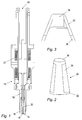
- Figure 1 is a cross-section of a fuel injector forming an embodiment of the present invention;
- Figure 2 is a perspective view of the filter of Figure 1; and
- Figure 3 is a cross-section of the upper region of the filter of Figure 2.
- Figure 1 shows a fuel injector of the outwardly opening type having an
injector body 10, having atip portion 12 terminating in aspray aperture 14. Apintle 16 extends within thetip portion 12 for axial movement therein between an extended position and a retracted position. Thepintle 16 terminates in anexternal head portion 18 engageable with thespray aperture 14 when in its retracted position to seal thespray aperture 14. Resilient means (not shown) bias thepintle 16 to its retracted position and a selectively energisible and de-energisibleelectromagnetic actuator 22 is operable to selectively move thepintle 16 into its extended position to initiate a fuel injection operation. Pressurised fuel is supplied to the fuel injector via aninlet port 24. - As shown in Figure 3, uppermost region of the frame of the filter is shaped such that the
aperture 34 formed therien defines a cylindrical sealing surface through which the pintle is a close sliding fit, said surface having an axial extent or width substantially equal to or greater than the diameter of theaperture 34 to ensure a good seal against the outer surface of the pintle without causing significant resistance to the axial movement of the pintle through theaperture 34. - A
filter 30 is provided within thetip portion 12 of theinjector body 10, downstream of thefuel inlet port 14 and upstream of thespray aperture 14. As can be best seen from Figure 2, thefilter 30 is in the form of a hollow truncated cone with abase region 32 having an outer diameter dimensioned to be a press fit against the inner sides of thetip portion 12 such that the filter is a press fit within the tip portion. The top or upper region of the cone terminates in anaperture 34 through which thepintle 16 passes, the aperture having an inner diameter dimensioned to be a close sliding fit over thepintle 16. - The
filter 30 is formed from a plastic frame having apertures in the side regions thereof within which apertures is mountedfilter material 36 through which the fuel must pass to reach thespray aperture 14 when the filter is located within thetip portion 12 of theinjector body 12. Thefilter material 36 is such that thefilter 30 is capable of removing particulate material of 30 microns or more in size. - The
filter 30 forms a barrier to the free flow of particle contaminated fuel. The filter can be pre-assembled to the valve group defined by the tip portion and its associated components prior to assembly into the remainder of the injector body. Thus the valve group can cleaned and purged of all residual contamination prior to assembly into the injector body and then installed into the remainder of the injector body comprising the actuator parts. The filter, being in a completely cleaned valve group assembly, can effectively filter the contamination that may be generated during the assembly and test phase of the injector construction. - It is also envisaged that the cleaned and purged pre-assembled valve group assembly could be used in applications other than in fuel injectors, where high purity and particulate contamination free liquids are to be dispensed, such as medical applications.
Claims (8)
- An internal filter for a fuel injector of an internal combustion engine, said filter (30) comprising a body in the form of a hollow tuncated cone comprising a base (32) having an outer diameter dimensioned to be a press fit against the inner surface of a tip portion of the fuel injector and terminating in an aperture (34) of reduced diameter through which a pintle of the fuel injector can pass with a close running clearance.
- A filter as claimed in claim 2, wherein the aperture (34) formed therein defines a cylindrical sealing surface through which the pintle is a close sliding fit, said surface having an axial extent or width substantially equal to or greater than the diameter of the aperture (34) to ensure a good seal against the outer surface of the pintle without causing significant resistance to the axial movement of the pintle through the aperture (34).
- A filter as claimed in any preceding claim, wherein said filter (30) comprises a frame having one or more regions of filter material (36) provided in apertures or windows formed in the side regions thereof.
- A filter as claimed in claim 3, wherein said frame comprises a lower portion, defining said base (32) adapted to be a press fit within the injector tip, and an upper portion, defining said aperture (36) through which the pintle passes, and a plurality of linking struts or members extending between said upper and lower portions to define a plurality of windows or openings having filter material (36) mounted therein.
- A filter as claimed in claim 3 or claim 4, wherein said frame is formed from a plastic material.
- A valve group for a fuel injector (10) of an internal combustion engine, said valve group comprising a body (12) having an internal space communicating with a fuel inlet and an outlet aperture (14) provided at a distal end of said body (12), a valve seat being provided at or adjacent said outlet aperture (14), a pintle (16) extending within the internal space of said body (12), the pintle (16) having a head (18)engageable with the valve seat and being axially moveable between a first position wherein said head (18) engages said valve seat and a second position wherein said head (18) is spaced from said valve seat; wherein a filter (30) is disposed within the internal space of said body (12) of the valve group downstream of the fuel inlet and upstream of the valve seat, said filter (30) said filter being in accordance with any of claims 1 to 5.
- A fuel injector (10) for an internal combustion engine, comprising an injector body having a fuel inlet (24) and a tip portion (12) defining a spray aperture (14) and having a valve seat; a pintle (16) extending within the tip portion (12), the pintle (16) having a head (18) engageable with the valve seat and being axially moveable between a first position wherein said head (18) engages said valve seat and a second position wherein said head (18) is spaced from said valve seat; resilient means biasing the pintle (16) to said first position; actuating means (22) for selectively moving the pintle into said second position; wherein a filter (30) is disposed internally of the tip portion (12) of the injector body downstream of the fuel inlet (24) and upstream of the valve seat, said filter (30) being in accordance with any of claims 1 to 5.
- A fuel injector as claimed in claim 7, wherein the fuel injector (10) is an outwardly opening injector.
Priority Applications (6)
| Application Number | Priority Date | Filing Date | Title |
|---|---|---|---|
| AT05256796T ATE390553T1 (en) | 2005-11-02 | 2005-11-02 | INNER FILTER FOR A FUEL INJECTION VALVE |
| EP05256796A EP1783360B1 (en) | 2005-11-02 | 2005-11-02 | Internal filter for a fuel injector |
| DE602005005688T DE602005005688T2 (en) | 2005-11-02 | 2005-11-02 | Inner filter for a fuel injector |
| JP2006201133A JP2007127116A (en) | 2005-11-02 | 2006-07-24 | Internal filter for fuel injector |
| KR1020060083727A KR100880766B1 (en) | 2005-11-02 | 2006-08-31 | Valve group for fuel injectors in internal combustion engines with filters |
| US11/592,005 US7434567B2 (en) | 2005-11-02 | 2006-11-02 | Internal filter for a fuel injector |
Applications Claiming Priority (1)
| Application Number | Priority Date | Filing Date | Title |
|---|---|---|---|
| EP05256796A EP1783360B1 (en) | 2005-11-02 | 2005-11-02 | Internal filter for a fuel injector |
Publications (2)
| Publication Number | Publication Date |
|---|---|
| EP1783360A1 true EP1783360A1 (en) | 2007-05-09 |
| EP1783360B1 EP1783360B1 (en) | 2008-03-26 |
Family
ID=36088449
Family Applications (1)
| Application Number | Title | Priority Date | Filing Date |
|---|---|---|---|
| EP05256796A Expired - Lifetime EP1783360B1 (en) | 2005-11-02 | 2005-11-02 | Internal filter for a fuel injector |
Country Status (6)
| Country | Link |
|---|---|
| US (1) | US7434567B2 (en) |
| EP (1) | EP1783360B1 (en) |
| JP (1) | JP2007127116A (en) |
| KR (1) | KR100880766B1 (en) |
| AT (1) | ATE390553T1 (en) |
| DE (1) | DE602005005688T2 (en) |
Families Citing this family (3)
| Publication number | Priority date | Publication date | Assignee | Title |
|---|---|---|---|---|
| US7617991B2 (en) * | 2006-03-31 | 2009-11-17 | Delphi Technologies, Inc. | Injector fuel filter with built-in orifice for flow restriction |
| DE102016206314B4 (en) * | 2016-04-14 | 2018-12-27 | Robert Bosch Gmbh | fuel Injector |
| US12006902B2 (en) | 2021-03-03 | 2024-06-11 | Caterpillar Inc. | Fuel injector and fuel system having integral filter supported in valve seat plate, and valve seat plate and filter assembly |
Citations (4)
| Publication number | Priority date | Publication date | Assignee | Title |
|---|---|---|---|---|
| US5967424A (en) * | 1998-06-24 | 1999-10-19 | General Motors Corporation | Fuel injector filter |
| EP0971124A2 (en) * | 1998-06-08 | 2000-01-12 | Delphi Technologies, Inc. | Filter for fuel injector |
| EP1229239A2 (en) * | 2001-02-02 | 2002-08-07 | Siemens VDO Automotive Corporation | Combined filter and adjuster for a fuel injector |
| US20030209615A1 (en) * | 2002-05-13 | 2003-11-13 | Hitachi Unisia Automotive, Ltd. | Fuel injection valve |
Family Cites Families (14)
| Publication number | Priority date | Publication date | Assignee | Title |
|---|---|---|---|---|
| US1964218A (en) * | 1931-03-17 | 1934-06-26 | Firm Hannoversche Maschb Actie | Means for filtering the fuel supplied to the injector nozzles of internal combustion engines |
| US3499605A (en) * | 1967-12-22 | 1970-03-10 | Allis Chalmers Mfg Co | Nozzle holder |
| US3829014A (en) * | 1972-11-29 | 1974-08-13 | Stanadyne Inc | Fuel injector having self-cleaning filter |
| US5335863A (en) * | 1993-05-03 | 1994-08-09 | Siemens Automotive L.P. | Filter cartridge mounting for a top-feed fuel injector |
| US5692723A (en) * | 1995-06-06 | 1997-12-02 | Sagem-Lucas, Inc. | Electromagnetically actuated disc-type valve |
| DE19601019A1 (en) * | 1996-01-13 | 1997-07-17 | Bosch Gmbh Robert | Injection valve for internal combustion engine |
| US6036120A (en) * | 1998-03-27 | 2000-03-14 | General Motors Corporation | Fuel injector and method |
| DE19835693A1 (en) * | 1998-08-07 | 2000-02-10 | Bosch Gmbh Robert | Fuel injector |
| DE19843344A1 (en) * | 1998-09-22 | 2000-03-23 | Bosch Gmbh Robert | Fuel injection valve for internal combustion engine has valve member axially movably positioned in bore of valve body, which has valve sealing surface at combustion chamber-side end |
| DE10108464A1 (en) * | 2001-02-22 | 2002-09-05 | Bosch Gmbh Robert | Fuel injector |
| EP1296057B1 (en) * | 2001-09-19 | 2011-01-05 | Filtertek Inc. | Integrated fuel filter and calibration tube for a fuel injector |
| US6732959B2 (en) * | 2002-09-04 | 2004-05-11 | Delphi Technologies, Inc. | Dual-coil outwardly-opening fuel injector |
| DE10334785A1 (en) * | 2003-07-30 | 2005-02-24 | Robert Bosch Gmbh | Fuel injection valve and method for its assembly |
| DE102005040361A1 (en) * | 2005-08-26 | 2007-03-01 | Robert Bosch Gmbh | Metallic components for electromagnetically operated fuel injection valve, have surface-roughening structure that is provided by laser, where metal oxides such as chrome oxides are deposited in roughening structure |
-
2005
- 2005-11-02 DE DE602005005688T patent/DE602005005688T2/en not_active Expired - Lifetime
- 2005-11-02 AT AT05256796T patent/ATE390553T1/en not_active IP Right Cessation
- 2005-11-02 EP EP05256796A patent/EP1783360B1/en not_active Expired - Lifetime
-
2006
- 2006-07-24 JP JP2006201133A patent/JP2007127116A/en not_active Withdrawn
- 2006-08-31 KR KR1020060083727A patent/KR100880766B1/en not_active Expired - Fee Related
- 2006-11-02 US US11/592,005 patent/US7434567B2/en not_active Expired - Fee Related
Patent Citations (4)
| Publication number | Priority date | Publication date | Assignee | Title |
|---|---|---|---|---|
| EP0971124A2 (en) * | 1998-06-08 | 2000-01-12 | Delphi Technologies, Inc. | Filter for fuel injector |
| US5967424A (en) * | 1998-06-24 | 1999-10-19 | General Motors Corporation | Fuel injector filter |
| EP1229239A2 (en) * | 2001-02-02 | 2002-08-07 | Siemens VDO Automotive Corporation | Combined filter and adjuster for a fuel injector |
| US20030209615A1 (en) * | 2002-05-13 | 2003-11-13 | Hitachi Unisia Automotive, Ltd. | Fuel injection valve |
Also Published As
| Publication number | Publication date |
|---|---|
| KR100880766B1 (en) | 2009-02-02 |
| DE602005005688D1 (en) | 2008-05-08 |
| KR20070047687A (en) | 2007-05-07 |
| US7434567B2 (en) | 2008-10-14 |
| ATE390553T1 (en) | 2008-04-15 |
| DE602005005688T2 (en) | 2009-04-09 |
| US20070095953A1 (en) | 2007-05-03 |
| JP2007127116A (en) | 2007-05-24 |
| EP1783360B1 (en) | 2008-03-26 |
Similar Documents
| Publication | Publication Date | Title |
|---|---|---|
| US8517183B2 (en) | No filter no run fluid filtration system | |
| EP0760318A1 (en) | Window washing arrangement for motor vehicles, in particular for the vehicle headlights | |
| DE10109410A1 (en) | Fuel injector | |
| EP3620220A1 (en) | Filter device | |
| WO2018140254A1 (en) | Filter for a fuel injector | |
| WO2011061148A1 (en) | Intake manifold section and intake system | |
| DE102008011701A1 (en) | Exhaust gas recirculation valve for internal combustion engine of motor vehicle, has filter for purifying leakage gas in inner side of drive housing part and/or at outer side of outer wall of drive housing part | |
| EP1907689B1 (en) | Fuel injector | |
| EP1783360B1 (en) | Internal filter for a fuel injector | |
| EP2738365B1 (en) | Line valve for a fluid line | |
| EP3691769B1 (en) | Filter element with venting function for suspension on a filter head, and filter system | |
| DE102011087964A1 (en) | Valve i.e. canister purge valve, for device for metered supply of fuel to combustion engine of motor car, has gasket clamped between valve element and valve-fixed attachment and impinging valve element with closing force | |
| CN110295976A (en) | Fluid ejector with directing plate | |
| DE102019100402B3 (en) | Valve device for selectively enabling or blocking an exhaust gas recirculation or secondary air flow for an exhaust gas aftertreatment system | |
| US10197034B2 (en) | Nozzle assembly and fuel injection valve for a combustion engine | |
| EP2898198B1 (en) | Injection valve and exhaust gas aftertreatment apparatus | |
| DE29917563U1 (en) | Fluid filter with housing-fixed drain dome | |
| EP4010580B1 (en) | Fuel injector with a flow limiter for a fuel injection system | |
| DE102006047557A1 (en) | Fuel injection device for internal-combustion engine, has filters cleaning fuel flowing to connections, where filters are held in rings, and rings are held in cylindric inner chamber of fuel distributor using press-fit | |
| EP2354531A1 (en) | Valve assembly for an injection valve and injection valve | |
| EP1702156B1 (en) | Fuel injection valve | |
| KR20150088260A (en) | Injection valve | |
| WO2019174815A1 (en) | Filter element for liquid medium, and pump with filter element | |
| WO2014067695A1 (en) | Injection valve and exhaust gas aftertreatment device | |
| WO2025131354A1 (en) | Injector for injecting a gaseous medium |
Legal Events
| Date | Code | Title | Description |
|---|---|---|---|
| PUAI | Public reference made under article 153(3) epc to a published international application that has entered the european phase |
Free format text: ORIGINAL CODE: 0009012 |
|
| 17P | Request for examination filed |
Effective date: 20060511 |
|
| AK | Designated contracting states |
Kind code of ref document: A1 Designated state(s): AT BE BG CH CY CZ DE DK EE ES FI FR GB GR HU IE IS IT LI LT LU LV MC NL PL PT RO SE SI SK TR |
|
| AX | Request for extension of the european patent |
Extension state: AL BA HR MK YU |
|
| GRAP | Despatch of communication of intention to grant a patent |
Free format text: ORIGINAL CODE: EPIDOSNIGR1 |
|
| GRAS | Grant fee paid |
Free format text: ORIGINAL CODE: EPIDOSNIGR3 |
|
| AKX | Designation fees paid |
Designated state(s): AT BE BG CH CY CZ DE DK EE ES FI FR GB GR HU IE IS IT LI LT LU LV MC NL PL PT RO SE SI SK TR |
|
| GRAA | (expected) grant |
Free format text: ORIGINAL CODE: 0009210 |
|
| AK | Designated contracting states |
Kind code of ref document: B1 Designated state(s): AT BE BG CH CY CZ DE DK EE ES FI FR GB GR HU IE IS IT LI LT LU LV MC NL PL PT RO SE SI SK TR |
|
| REG | Reference to a national code |
Ref country code: GB Ref legal event code: FG4D |
|
| REG | Reference to a national code |
Ref country code: CH Ref legal event code: EP Ref country code: IE Ref legal event code: FG4D |
|
| REF | Corresponds to: |
Ref document number: 602005005688 Country of ref document: DE Date of ref document: 20080508 Kind code of ref document: P |
|
| PG25 | Lapsed in a contracting state [announced via postgrant information from national office to epo] |
Ref country code: FI Free format text: LAPSE BECAUSE OF FAILURE TO SUBMIT A TRANSLATION OF THE DESCRIPTION OR TO PAY THE FEE WITHIN THE PRESCRIBED TIME-LIMIT Effective date: 20080326 |
|
| PG25 | Lapsed in a contracting state [announced via postgrant information from national office to epo] |
Ref country code: AT Free format text: LAPSE BECAUSE OF FAILURE TO SUBMIT A TRANSLATION OF THE DESCRIPTION OR TO PAY THE FEE WITHIN THE PRESCRIBED TIME-LIMIT Effective date: 20080326 |
|
| NLV1 | Nl: lapsed or annulled due to failure to fulfill the requirements of art. 29p and 29m of the patents act | ||
| PG25 | Lapsed in a contracting state [announced via postgrant information from national office to epo] |
Ref country code: SI Free format text: LAPSE BECAUSE OF FAILURE TO SUBMIT A TRANSLATION OF THE DESCRIPTION OR TO PAY THE FEE WITHIN THE PRESCRIBED TIME-LIMIT Effective date: 20080326 Ref country code: LV Free format text: LAPSE BECAUSE OF FAILURE TO SUBMIT A TRANSLATION OF THE DESCRIPTION OR TO PAY THE FEE WITHIN THE PRESCRIBED TIME-LIMIT Effective date: 20080326 Ref country code: PL Free format text: LAPSE BECAUSE OF FAILURE TO SUBMIT A TRANSLATION OF THE DESCRIPTION OR TO PAY THE FEE WITHIN THE PRESCRIBED TIME-LIMIT Effective date: 20080326 Ref country code: BE Free format text: LAPSE BECAUSE OF FAILURE TO SUBMIT A TRANSLATION OF THE DESCRIPTION OR TO PAY THE FEE WITHIN THE PRESCRIBED TIME-LIMIT Effective date: 20080326 |
|
| PG25 | Lapsed in a contracting state [announced via postgrant information from national office to epo] |
Ref country code: CZ Free format text: LAPSE BECAUSE OF FAILURE TO SUBMIT A TRANSLATION OF THE DESCRIPTION OR TO PAY THE FEE WITHIN THE PRESCRIBED TIME-LIMIT Effective date: 20080326 Ref country code: ES Free format text: LAPSE BECAUSE OF FAILURE TO SUBMIT A TRANSLATION OF THE DESCRIPTION OR TO PAY THE FEE WITHIN THE PRESCRIBED TIME-LIMIT Effective date: 20080707 Ref country code: PT Free format text: LAPSE BECAUSE OF FAILURE TO SUBMIT A TRANSLATION OF THE DESCRIPTION OR TO PAY THE FEE WITHIN THE PRESCRIBED TIME-LIMIT Effective date: 20080901 Ref country code: SE Free format text: LAPSE BECAUSE OF FAILURE TO SUBMIT A TRANSLATION OF THE DESCRIPTION OR TO PAY THE FEE WITHIN THE PRESCRIBED TIME-LIMIT Effective date: 20080626 Ref country code: SK Free format text: LAPSE BECAUSE OF FAILURE TO SUBMIT A TRANSLATION OF THE DESCRIPTION OR TO PAY THE FEE WITHIN THE PRESCRIBED TIME-LIMIT Effective date: 20080326 |
|
| ET | Fr: translation filed | ||
| PG25 | Lapsed in a contracting state [announced via postgrant information from national office to epo] |
Ref country code: RO Free format text: LAPSE BECAUSE OF FAILURE TO SUBMIT A TRANSLATION OF THE DESCRIPTION OR TO PAY THE FEE WITHIN THE PRESCRIBED TIME-LIMIT Effective date: 20080326 Ref country code: NL Free format text: LAPSE BECAUSE OF FAILURE TO SUBMIT A TRANSLATION OF THE DESCRIPTION OR TO PAY THE FEE WITHIN THE PRESCRIBED TIME-LIMIT Effective date: 20080326 |
|
| PG25 | Lapsed in a contracting state [announced via postgrant information from national office to epo] |
Ref country code: IS Free format text: LAPSE BECAUSE OF FAILURE TO SUBMIT A TRANSLATION OF THE DESCRIPTION OR TO PAY THE FEE WITHIN THE PRESCRIBED TIME-LIMIT Effective date: 20080726 |
|
| PG25 | Lapsed in a contracting state [announced via postgrant information from national office to epo] |
Ref country code: LT Free format text: LAPSE BECAUSE OF FAILURE TO SUBMIT A TRANSLATION OF THE DESCRIPTION OR TO PAY THE FEE WITHIN THE PRESCRIBED TIME-LIMIT Effective date: 20080326 Ref country code: DK Free format text: LAPSE BECAUSE OF FAILURE TO SUBMIT A TRANSLATION OF THE DESCRIPTION OR TO PAY THE FEE WITHIN THE PRESCRIBED TIME-LIMIT Effective date: 20080326 |
|
| PLBE | No opposition filed within time limit |
Free format text: ORIGINAL CODE: 0009261 |
|
| STAA | Information on the status of an ep patent application or granted ep patent |
Free format text: STATUS: NO OPPOSITION FILED WITHIN TIME LIMIT |
|
| 26N | No opposition filed |
Effective date: 20081230 |
|
| PG25 | Lapsed in a contracting state [announced via postgrant information from national office to epo] |
Ref country code: EE Free format text: LAPSE BECAUSE OF FAILURE TO SUBMIT A TRANSLATION OF THE DESCRIPTION OR TO PAY THE FEE WITHIN THE PRESCRIBED TIME-LIMIT Effective date: 20080326 Ref country code: BG Free format text: LAPSE BECAUSE OF FAILURE TO SUBMIT A TRANSLATION OF THE DESCRIPTION OR TO PAY THE FEE WITHIN THE PRESCRIBED TIME-LIMIT Effective date: 20080626 |
|
| PG25 | Lapsed in a contracting state [announced via postgrant information from national office to epo] |
Ref country code: MC Free format text: LAPSE BECAUSE OF NON-PAYMENT OF DUE FEES Effective date: 20081130 |
|
| PG25 | Lapsed in a contracting state [announced via postgrant information from national office to epo] |
Ref country code: CY Free format text: LAPSE BECAUSE OF FAILURE TO SUBMIT A TRANSLATION OF THE DESCRIPTION OR TO PAY THE FEE WITHIN THE PRESCRIBED TIME-LIMIT Effective date: 20080326 |
|
| PG25 | Lapsed in a contracting state [announced via postgrant information from national office to epo] |
Ref country code: IE Free format text: LAPSE BECAUSE OF NON-PAYMENT OF DUE FEES Effective date: 20081103 |
|
| PGFP | Annual fee paid to national office [announced via postgrant information from national office to epo] |
Ref country code: DE Payment date: 20091029 Year of fee payment: 5 |
|
| PGFP | Annual fee paid to national office [announced via postgrant information from national office to epo] |
Ref country code: FR Payment date: 20091123 Year of fee payment: 5 Ref country code: IT Payment date: 20091112 Year of fee payment: 5 |
|
| REG | Reference to a national code |
Ref country code: CH Ref legal event code: PL |
|
| GBPC | Gb: european patent ceased through non-payment of renewal fee |
Effective date: 20091102 |
|
| PG25 | Lapsed in a contracting state [announced via postgrant information from national office to epo] |
Ref country code: LU Free format text: LAPSE BECAUSE OF NON-PAYMENT OF DUE FEES Effective date: 20081102 Ref country code: HU Free format text: LAPSE BECAUSE OF FAILURE TO SUBMIT A TRANSLATION OF THE DESCRIPTION OR TO PAY THE FEE WITHIN THE PRESCRIBED TIME-LIMIT Effective date: 20080927 |
|
| PG25 | Lapsed in a contracting state [announced via postgrant information from national office to epo] |
Ref country code: TR Free format text: LAPSE BECAUSE OF FAILURE TO SUBMIT A TRANSLATION OF THE DESCRIPTION OR TO PAY THE FEE WITHIN THE PRESCRIBED TIME-LIMIT Effective date: 20080326 |
|
| PG25 | Lapsed in a contracting state [announced via postgrant information from national office to epo] |
Ref country code: LI Free format text: LAPSE BECAUSE OF NON-PAYMENT OF DUE FEES Effective date: 20091130 Ref country code: GR Free format text: LAPSE BECAUSE OF FAILURE TO SUBMIT A TRANSLATION OF THE DESCRIPTION OR TO PAY THE FEE WITHIN THE PRESCRIBED TIME-LIMIT Effective date: 20080627 Ref country code: CH Free format text: LAPSE BECAUSE OF NON-PAYMENT OF DUE FEES Effective date: 20091130 |
|
| PG25 | Lapsed in a contracting state [announced via postgrant information from national office to epo] |
Ref country code: GB Free format text: LAPSE BECAUSE OF NON-PAYMENT OF DUE FEES Effective date: 20091102 |
|
| REG | Reference to a national code |
Ref country code: FR Ref legal event code: ST Effective date: 20110801 |
|
| REG | Reference to a national code |
Ref country code: DE Ref legal event code: R119 Ref document number: 602005005688 Country of ref document: DE Effective date: 20110601 Ref country code: DE Ref legal event code: R119 Ref document number: 602005005688 Country of ref document: DE Effective date: 20110531 |
|
| PG25 | Lapsed in a contracting state [announced via postgrant information from national office to epo] |
Ref country code: FR Free format text: LAPSE BECAUSE OF NON-PAYMENT OF DUE FEES Effective date: 20101130 |
|
| PG25 | Lapsed in a contracting state [announced via postgrant information from national office to epo] |
Ref country code: IT Free format text: LAPSE BECAUSE OF NON-PAYMENT OF DUE FEES Effective date: 20101102 |
|
| PG25 | Lapsed in a contracting state [announced via postgrant information from national office to epo] |
Ref country code: DE Free format text: LAPSE BECAUSE OF NON-PAYMENT OF DUE FEES Effective date: 20110531 |