EP1783333A1 - Variable cam phaser apparatus - Google Patents
Variable cam phaser apparatus Download PDFInfo
- Publication number
- EP1783333A1 EP1783333A1 EP05256822A EP05256822A EP1783333A1 EP 1783333 A1 EP1783333 A1 EP 1783333A1 EP 05256822 A EP05256822 A EP 05256822A EP 05256822 A EP05256822 A EP 05256822A EP 1783333 A1 EP1783333 A1 EP 1783333A1
- Authority
- EP
- European Patent Office
- Prior art keywords
- drive
- actuator
- driven members
- follower
- coupling means
- Prior art date
- Legal status (The legal status is an assumption and is not a legal conclusion. Google has not performed a legal analysis and makes no representation as to the accuracy of the status listed.)
- Withdrawn
Links
- RDYMFSUJUZBWLH-UHFFFAOYSA-N endosulfan Chemical compound C12COS(=O)OCC2C2(Cl)C(Cl)=C(Cl)C1(Cl)C2(Cl)Cl RDYMFSUJUZBWLH-UHFFFAOYSA-N 0.000 title claims abstract description 8
- 230000008878 coupling Effects 0.000 claims abstract description 16
- 238000010168 coupling process Methods 0.000 claims abstract description 16
- 238000005859 coupling reaction Methods 0.000 claims abstract description 16
- 238000006073 displacement reaction Methods 0.000 claims abstract description 12
- 230000015572 biosynthetic process Effects 0.000 claims description 2
- 238000005755 formation reaction Methods 0.000 claims description 2
- 230000001939 inductive effect Effects 0.000 claims description 2
- 238000006243 chemical reaction Methods 0.000 description 1
- 238000000034 method Methods 0.000 description 1
- 238000012986 modification Methods 0.000 description 1
- 230000004048 modification Effects 0.000 description 1
- 230000000979 retarding effect Effects 0.000 description 1
Images
Classifications
-
- F—MECHANICAL ENGINEERING; LIGHTING; HEATING; WEAPONS; BLASTING
- F01—MACHINES OR ENGINES IN GENERAL; ENGINE PLANTS IN GENERAL; STEAM ENGINES
- F01L—CYCLICALLY OPERATING VALVES FOR MACHINES OR ENGINES
- F01L1/00—Valve-gear or valve arrangements, e.g. lift-valve gear
- F01L1/34—Valve-gear or valve arrangements, e.g. lift-valve gear characterised by the provision of means for changing the timing of the valves without changing the duration of opening and without affecting the magnitude of the valve lift
- F01L1/344—Valve-gear or valve arrangements, e.g. lift-valve gear characterised by the provision of means for changing the timing of the valves without changing the duration of opening and without affecting the magnitude of the valve lift changing the angular relationship between crankshaft and camshaft, e.g. using helicoidal gear
Definitions
- the present invention relates to a cam phaser apparatus, particularly, but not exclusively a variable cam phaser apparatus used in valve trains of automobile engines.
- cam phase i.e. the timing of the opening and closing of the valves
- Such system are required to efficiently convert rotational movement from the drive shaft into rotational movement of the cam shaft whilst allowing dislocation between these rotational movements in order to allow variation of the cam phase.
- Current systems typically utilise hydraulic actuators using high pressure oil to enable relative angular displacement between drive and driven members (e.g. cam sprocket and cam shaft) of the valve train.
- a variable cam phaser comprising coaxial drive and driven members drivingly connected by a coupling means, said coupling means enabling said drive and driven members to be relatively angularly adjusted while maintaining driving engagement therebetween, the coupling means comprising at least one actuator mounted on one of said drive and driven members, the actuator including a displacement member engaging and co-operable with a follower mounted on the other of said drive and driven members, whereby operation of said actuator causes relative angular displacement between the drive and driven members.
- the displacement member comprises a rotatable elongate member extending from and being rotatable by said actuator, said elongate member being arranged substantially tangentially to a circle coaxial with the drive and driven members, the elongate member being provided with a threaded portion engaging said follower, said follower having formations cooperating with said threaded portion whereby rotation of the elongate member causes axial displacement of the follower with respect to the elongate member.
- the or each actuator and the or each follower may be respectively mounted for pivotal movement about an axis substantially parallel to the rotational axis of the drive or driven member.
- said actuator comprises an electric motor. Electrical power may be supplied to the motor via slip rings mounted on a shaft connected to and coaxial with one of said drive and driven members.
- a camshaft 10 is typically driven by a cam sprocket 12 which is in turn rotatably driven by the crankshaft of the engine via a toothed drive belt or chain (not shown).
- a coupling means provides a connection between the cam shaft 10 and sprocket 12 and enables the camshaft 10 and sprocket 12 to be relatively angularly adjusted while maintaining driving engagement therebetween, as will be described below.
- the coupling means comprises two direct current electric motors 14,16 mounted on radially extending support members 18,20 connected to the camshaft 12.
- the output shaft from each motor 14,16 comprises a threaded lead screw 22,24.
- Each electric motor 14,16 is pivotally mounted on the respective support member 18,20 to permit each motor 14,16 to pivot about an axis parallel to the rotational axis of the camshaft 10 and sprocket 12.
- Each lead screw 22,24 engages a cooperating nut 26,28 respectively mounted on the cam sprocket 12 whereby rotation of each lead screw 22,24 by the respective electric motor 14,16 causes translational movement of the associated nut 26,28 along the lead screw 22,24.
- Each nut 26,28 is pivotally mounted on the sprocket 12 to permit each nut 26,28 to pivot about an axis parallel to the rotational axis of the camshaft 10 and sprocket 12.
- the electric motors 14,16 are operated to rotate the lead screws 22,24 whereby each nut 26,28 translates along its associated lead screw 22,24 to adjust the angular position of the sprocket 12 with respect to the camshaft 10.
- Rotation of the lead screws 22,24 in a first direction will cause the nuts 26,28 to move away from the associated motor 14,16, advancing the timing of the opening and closing of the associated valves while rotation of the lead screws 22,24 in a second opposite direction will cause the nuts 26,28 to move towards the associated motor 14,16, retarding the timing of the opening and closing of the associated valves.
- a single electric motor 14' may be required with a single lead screw 22' and associated nut 26' mounted on the sprocket 12.
- a balance weight 40 on the sprocket 12 at a position radially opposite said motor 14'.
- the system described allows the phase of the cam shaft to be reliably altered whilst the engine is running.
- the cam phase may be advanced or retarded depending upon the direction in which the lead screws 22,24 are rotated. Such adjustment may be controlled by the engine management system of typical automobiles.
- the system therefore effectively allows the rotational position of the cam shaft 10 to be varied relative to the rotational position of the sprocket 12.
- the cam phase has been adjusted into the advanced / retarded position it will remain in that position until it is positively re-adjusted by the engine management system.
Landscapes
- Engineering & Computer Science (AREA)
- Mechanical Engineering (AREA)
- General Engineering & Computer Science (AREA)
- Valve Device For Special Equipments (AREA)
Abstract
A variable cam phaser apparatus comprising coaxial drive and driven members 10,12 drivingly connected by a coupling means, said coupling means enabling said drive and driven members to be relatively angularly adjusted while maintaining driving engagement therebetween, the coupling means comprising at least one actuator 14,16 mounted on one of said drive and driven members 10,12, the actuator 14,16 including a displacement member 22,24 engaging and co-operable with a follower 26,28 mounted on the other of said drive and driven members 10,12, whereby operation of said actuator 14,16 causes relative angular displacement between the drive and driven members 10,12.


Description
- The present invention relates to a cam phaser apparatus, particularly, but not exclusively a variable cam phaser apparatus used in valve trains of automobile engines.
- It is desirable to be able to be able to adjust the cam phase (i.e. the timing of the opening and closing of the valves) of engines during engine operation in order to improve engine performance and / or emissions. Various types of arrangements capable of achieving this adjustment exist. Such system are required to efficiently convert rotational movement from the drive shaft into rotational movement of the cam shaft whilst allowing dislocation between these rotational movements in order to allow variation of the cam phase. Current systems typically utilise hydraulic actuators using high pressure oil to enable relative angular displacement between drive and driven members (e.g. cam sprocket and cam shaft) of the valve train.
- Such systems have difficulty operating at extremes of temperature, in particular during engine start up when the oil is cold, due to temperature related viscosity changes of the oil.
- Whilst attempts have been made to design electrically actuated variable cam phase arrangement, such usually require a complex arrangement of planetary gears or clutch arrangements which have the disadvantage of producing large frictional losses in the conversion process. The complex arrangement of such systems can also introduce controllability and reliability problems.
- According to the present invention there is provided a variable cam phaser comprising coaxial drive and driven members drivingly connected by a coupling means, said coupling means enabling said drive and driven members to be relatively angularly adjusted while maintaining driving engagement therebetween, the coupling means comprising at least one actuator mounted on one of said drive and driven members, the actuator including a displacement member engaging and co-operable with a follower mounted on the other of said drive and driven members, whereby operation of said actuator causes relative angular displacement between the drive and driven members.
- Preferably the displacement member comprises a rotatable elongate member extending from and being rotatable by said actuator, said elongate member being arranged substantially tangentially to a circle coaxial with the drive and driven members, the elongate member being provided with a threaded portion engaging said follower, said follower having formations cooperating with said threaded portion whereby rotation of the elongate member causes axial displacement of the follower with respect to the elongate member. The or each actuator and the or each follower may be respectively mounted for pivotal movement about an axis substantially parallel to the rotational axis of the drive or driven member.
- Preferably said actuator comprises an electric motor. Electrical power may be supplied to the motor via slip rings mounted on a shaft connected to and coaxial with one of said drive and driven members.
- An embodiment of the apparatus according to the present invention will now be described, with reference to the accompanying drawings, in which:-
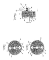
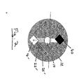
- Fig.1A is a side view of a cam phaser apparatus according to the present invention;
- Fig. 1B is an end view of the apparatus of Fig. 1A;
- Fig. 1C is an end view of the apparatus of Fig. 1A showing the cam phase adjusted from that position shown in Fig. 1B; and
- Fig 2 is an end view of a cam phaser apparatus according to a second embodiment of the present invention.
- As shown in the drawings, a
camshaft 10 is typically driven by acam sprocket 12 which is in turn rotatably driven by the crankshaft of the engine via a toothed drive belt or chain (not shown). - A coupling means provides a connection between the
cam shaft 10 andsprocket 12 and enables thecamshaft 10 andsprocket 12 to be relatively angularly adjusted while maintaining driving engagement therebetween, as will be described below. - The coupling means comprises two direct current
electric motors support members camshaft 12. - The output shaft from each
motor lead screw - Each
electric motor respective support member motor camshaft 10 andsprocket 12. - Each
lead screw nut lead screw electric motor nut lead screw nut sprocket 12 to permit eachnut camshaft 10 and sprocket 12. - As shown in Fig.1A, electrical power is supplied to the
motors brushes engaging slip rings motors - In use, the
electric motors lead screws nut lead screw sprocket 12 with respect to thecamshaft 10. Rotation of thelead screws nuts motor lead screws nuts motor - In an alternative embodiment, shown in Fig. 2, only a single electric motor 14' may be required with a single lead screw 22' and associated nut 26' mounted on the
sprocket 12. In such embodiment, in order to avoid rotational imbalance, it is necessary to mount abalance weight 40 on thesprocket 12 at a position radially opposite said motor 14'. - The system described allows the phase of the cam shaft to be reliably altered whilst the engine is running. In this regard, it should be noted that the cam phase may be advanced or retarded depending upon the direction in which the
lead screws cam shaft 10 to be varied relative to the rotational position of thesprocket 12. Importantly, once the cam phase has been adjusted into the advanced / retarded position it will remain in that position until it is positively re-adjusted by the engine management system. - Modifications and improvement may be made to the foregoing, without departing from the scope of the present invention, for example:-
- Although the present invention has been described in relation to automobile engines, it could be used in similar engines used in other applications.
Claims (10)
- A variable cam phaser apparatus comprising coaxial drive and driven members drivingly connected by a coupling means, said coupling means enabling said drive and driven members to be relatively angularly adjusted while maintaining driving engagement therebetween, the coupling means comprising at least one actuator mounted on one of said drive and driven members, the actuator including a displacement member engaging and co-operable with a follower mounted on the other of said drive and driven members, whereby operation of said actuator causes relative angular displacement between the drive and driven members.
- An apparatus as claimed in claim 1, wherein the displacement member comprises a rotatable elongate member extending from and being rotatable by said actuator, said elongate member being arranged substantially tangentially to a circle coaxial with the drive and driven members, the elongate member being provided with a threaded portion engaging said follower, said follower having formations cooperating with said threaded portion whereby rotation of the elongate member causes axial displacement of the follower with respect to the elongate member.
- An apparatus as claimed in any preceding claim wherein the or each actuator and the or each follower are respectively mounted for pivotal movement about an axis substantially parallel to the rotational axis of the drive or driven member.
- An apparatus as claimed in any preceding claim, wherein said actuator comprises an electric motor.
- An apparatus as claimed in claim 4, wherein electrical power is supplied to the motor via slip rings mounted on a shaft connected to and coaxial with one of said drive and driven members.
- An apparatus as claimed in claim 4, wherein electrical power is supplied to the motor via an inductive coupling.
- An apparatus as claimed in any preceding claims, wherein said coupling means comprises first and second actuators respectively mounted on radially opposite sides of one of said drive or driven members to provide rotational balance of the coupling means.
- An apparatus as claimed in any of claims 1 to 6, wherein said actuator is mounted to one side of the rotational axis of said drive or driven member and a balance weight is mounted on a radially opposite side, said balance weight having a mass substantially equal to that of the actuator and the associated displacement member and follower whereby the coupling means is rotationally balanced.
- An apparatus as claimed in any preceding claim wherein the or each actuator is mounted on a radially extending support member provided on the driven member, the or each follower being mounted on the drive member.
- An apparatus as claimed in any preceding claim wherein said drive member comprises a cam sprocket and said driven member comprises a cam shaft.
Priority Applications (1)
| Application Number | Priority Date | Filing Date | Title |
|---|---|---|---|
| EP05256822A EP1783333A1 (en) | 2005-11-04 | 2005-11-04 | Variable cam phaser apparatus |
Applications Claiming Priority (1)
| Application Number | Priority Date | Filing Date | Title |
|---|---|---|---|
| EP05256822A EP1783333A1 (en) | 2005-11-04 | 2005-11-04 | Variable cam phaser apparatus |
Publications (1)
| Publication Number | Publication Date |
|---|---|
| EP1783333A1 true EP1783333A1 (en) | 2007-05-09 |
Family
ID=36282658
Family Applications (1)
| Application Number | Title | Priority Date | Filing Date |
|---|---|---|---|
| EP05256822A Withdrawn EP1783333A1 (en) | 2005-11-04 | 2005-11-04 | Variable cam phaser apparatus |
Country Status (1)
| Country | Link |
|---|---|
| EP (1) | EP1783333A1 (en) |
Citations (6)
| Publication number | Priority date | Publication date | Assignee | Title |
|---|---|---|---|---|
| US1691408A (en) * | 1927-03-18 | 1928-11-13 | Palmer Walter Tuttle | Timing device |
| US3812734A (en) * | 1973-01-30 | 1974-05-28 | E Hamburger | Externally adjustable cam timer |
| DE4040486A1 (en) * | 1990-06-22 | 1992-01-02 | Schrick Gmbh Dr | DEVICE IN COMBUSTION ENGINES FOR ROTATING THE CAMSHAFT RELATIVE TO THE CAMSHAFT DRIVE WHEEL |
| US5156119A (en) * | 1990-07-31 | 1992-10-20 | Atsugi Unisia Corp. | Valve timing control apparatus |
| EP1030090A2 (en) * | 1999-02-18 | 2000-08-23 | Continental ISAD Electronic Systems GmbH & Co. KG | Gas shuttle valve with electromagnetic actuation |
| US20010006050A1 (en) * | 2000-01-04 | 2001-07-05 | Siegfried Heer | Transmission |
-
2005
- 2005-11-04 EP EP05256822A patent/EP1783333A1/en not_active Withdrawn
Patent Citations (6)
| Publication number | Priority date | Publication date | Assignee | Title |
|---|---|---|---|---|
| US1691408A (en) * | 1927-03-18 | 1928-11-13 | Palmer Walter Tuttle | Timing device |
| US3812734A (en) * | 1973-01-30 | 1974-05-28 | E Hamburger | Externally adjustable cam timer |
| DE4040486A1 (en) * | 1990-06-22 | 1992-01-02 | Schrick Gmbh Dr | DEVICE IN COMBUSTION ENGINES FOR ROTATING THE CAMSHAFT RELATIVE TO THE CAMSHAFT DRIVE WHEEL |
| US5156119A (en) * | 1990-07-31 | 1992-10-20 | Atsugi Unisia Corp. | Valve timing control apparatus |
| EP1030090A2 (en) * | 1999-02-18 | 2000-08-23 | Continental ISAD Electronic Systems GmbH & Co. KG | Gas shuttle valve with electromagnetic actuation |
| US20010006050A1 (en) * | 2000-01-04 | 2001-07-05 | Siegfried Heer | Transmission |
Similar Documents
| Publication | Publication Date | Title |
|---|---|---|
| EP2006501A1 (en) | Variable cam phaser apparatus | |
| US7647904B2 (en) | Variable cam phaser apparatus | |
| CN106195134B (en) | Spring loaded planetary gear assembly | |
| CN102439265B (en) | Phaser assembly for an internal combustion engine | |
| US10233999B2 (en) | Off-axis-loaded anti-backlash planetary drive for e-phaser | |
| US20090120388A1 (en) | Electro-hydraulic hybrid camshaft phaser | |
| US10107154B2 (en) | Electric cam phaser with fixed sun planetary | |
| EP1914396A2 (en) | Camshaft phaser having a differential bevel gear system | |
| CN109307052B (en) | Low axial length high torque shaft phasing apparatus with speed reduction | |
| US7562645B2 (en) | Electromechanical camshaft phaser having a worm gear drive with a hypoid gear actuator | |
| US20030159670A1 (en) | Worm gear driven variable cam phaser | |
| KR101209725B1 (en) | Continuous variable valve timing apparatus | |
| US20190242277A1 (en) | Dual actuating variable cam | |
| US6457446B1 (en) | Phase control mechanism | |
| KR20150072977A (en) | Valve Train Layout Structure Including Cam Phaser and Camshaft-In-Camshaft | |
| KR101172332B1 (en) | Variable valve timing apparatus | |
| US20150176443A1 (en) | Chain-based transfer device | |
| US7036474B2 (en) | Control device and method for adjusting the angular velocity ratio between a camshaft and a crankshaft | |
| EP1801367A1 (en) | Variable cam phaser apparatus | |
| EP1813783B1 (en) | Cam phaser apparatus | |
| US20020170513A1 (en) | Phase control mechanism | |
| EP2009254A1 (en) | Variable cam phaser apparatus | |
| EP4028646B1 (en) | Internal combustion engine with camshaft valve phase variation device | |
| US20180216503A1 (en) | Travel stop for planetary gears of an electric phaser | |
| EP1785597A1 (en) | Cam phaser apparatus |
Legal Events
| Date | Code | Title | Description |
|---|---|---|---|
| PUAI | Public reference made under article 153(3) epc to a published international application that has entered the european phase |
Free format text: ORIGINAL CODE: 0009012 |
|
| AK | Designated contracting states |
Kind code of ref document: A1 Designated state(s): AT BE BG CH CY CZ DE DK EE ES FI FR GB GR HU IE IS IT LI LT LU LV MC NL PL PT RO SE SI SK TR |
|
| AX | Request for extension of the european patent |
Extension state: AL BA HR MK YU |
|
| AKX | Designation fees paid | ||
| REG | Reference to a national code |
Ref country code: DE Ref legal event code: 8566 |
|
| STAA | Information on the status of an ep patent application or granted ep patent |
Free format text: STATUS: THE APPLICATION IS DEEMED TO BE WITHDRAWN |
|
| 18D | Application deemed to be withdrawn |
Effective date: 20071110 |