EP1783091B1 - Device operating on ropes for use in lowering loads - Google Patents
Device operating on ropes for use in lowering loads Download PDFInfo
- Publication number
- EP1783091B1 EP1783091B1 EP06122589A EP06122589A EP1783091B1 EP 1783091 B1 EP1783091 B1 EP 1783091B1 EP 06122589 A EP06122589 A EP 06122589A EP 06122589 A EP06122589 A EP 06122589A EP 1783091 B1 EP1783091 B1 EP 1783091B1
- Authority
- EP
- European Patent Office
- Prior art keywords
- rope
- arrangement
- trapping
- guided
- paying out
- Prior art date
- Legal status (The legal status is an assumption and is not a legal conclusion. Google has not performed a legal analysis and makes no representation as to the accuracy of the status listed.)
- Not-in-force
Links
Images

Classifications
-
- A—HUMAN NECESSITIES
- A62—LIFE-SAVING; FIRE-FIGHTING
- A62B—DEVICES, APPARATUS OR METHODS FOR LIFE-SAVING
- A62B1/00—Devices for lowering persons from buildings or the like
- A62B1/06—Devices for lowering persons from buildings or the like by making use of rope-lowering devices
- A62B1/14—Devices for lowering persons from buildings or the like by making use of rope-lowering devices with brakes sliding on the rope
-
- B—PERFORMING OPERATIONS; TRANSPORTING
- B66—HOISTING; LIFTING; HAULING
- B66D—CAPSTANS; WINCHES; TACKLES, e.g. PULLEY BLOCKS; HOISTS
- B66D5/00—Braking or detent devices characterised by application to lifting or hoisting gear, e.g. for controlling the lowering of loads
- B66D5/02—Crane, lift hoist, or winch brakes operating on drums, barrels, or ropes
- B66D5/16—Crane, lift hoist, or winch brakes operating on drums, barrels, or ropes for action on ropes or cables
-
- B—PERFORMING OPERATIONS; TRANSPORTING
- B66—HOISTING; LIFTING; HAULING
- B66D—CAPSTANS; WINCHES; TACKLES, e.g. PULLEY BLOCKS; HOISTS
- B66D3/00—Portable or mobile lifting or hauling appliances
- B66D3/02—Manually-operated, e.g. lever-actuated, devices operating on ropes, cables, or chains for hauling in a mainly horizontal direction
-
- B—PERFORMING OPERATIONS; TRANSPORTING
- B66—HOISTING; LIFTING; HAULING
- B66D—CAPSTANS; WINCHES; TACKLES, e.g. PULLEY BLOCKS; HOISTS
- B66D5/00—Braking or detent devices characterised by application to lifting or hoisting gear, e.g. for controlling the lowering of loads
Definitions
- This invention relates to a device for use, for example, in lowering loads that are supported by a rope.
- this invention relates to a device that may be used for manually lowering loads that are supported by a rope and pulley arrangement.
- the term "rope” is intended to mean any flexible elongate element suitable for transmitting forces.
- the term “rope” is to be taken, for example, to include cables and straps.
- a problem associated with the above described arrangement arises when lowering the load by manually paying out the rope.
- the operator releases the rope for any reason, a dangerous situation results because the load may fall freely to the ground.
- the rope may be tied in an "Italian hitch" around a karabiner.
- increased friction alone cannot accommodate situations in which the rope is completely released by the operator without a risk of the load falling freely.
- WO 02/055425 discloses a rope and pulley-type lifting device which allows a rope to be released with a suspended load falling freely to the ground.
- the device comprises a resiliently loaded cam for jamming the rope against a surface.
- the cam includes a pawl arm against which the free end of the rope may be urged to release the rope and allow it to move through the device to raise or lower a load in a controlled manner.
- a device for use in paying out a rope using the force from a load supported by the rope comprising: a rope trapping arrangement including an element having a groove for receiving the rope; and a rope guiding arrangement defining a channel such that the rope is able to move transversely within the channel, the channel having a first guided position in which the rope is out of the rope trapping arrangement, and a second guided position in which the rope is engaged into the rope trapping arrangement, wherein the rope guiding arrangement is adapted to guide the rope to the second guided position under the action of a resilient element, and wherein the device is operable in two modes: a first mode in which the rope is held by an operator of the device in the first guided position and the rope can be paid out; and a second mode in which the rope is released by an operator of the device, and the rope is guided transversely to the second guided position, thereby to trap the rope and prevent further paying out of the rope, wherein the device is characterised in that the groove of the rope trapping arrangement
- the invention provides a device which allows an operator to pay out a rope in a safe and controlled manner, and using the force from a load supported by the rope.
- the rope is held by the operator, it is in the first guided position and is not trapped by the rope trapping arrangement.
- the rope is safely guided into the second guided position and becomes trapped by the rope trapping arrangement. In this way, the risk of the load falling freely when the rope is released is minimised.
- the device further comprises a friction providing arrangement for controlling paying out of the rope.
- the friction providing arrangement may be positioned at one end of the rope trapping arrangement.
- the friction providing arrangement comprises a bar about which the rope is knotted.
- the bar may, for example, be provided as a karabiner and the knot may, for example, be an Italian hitch.
- the rope guiding arrangement is adapted to guide the rope to the second guiding position under the action of a resilient element.
- the rope guiding arrangement may again define a channel, with the rope moving transversely within the channel, and wherein an element such as a resiliently biased guide wheel urges the rope towards the second guiding position.
- the invention also provides a support arrangement comprising: a rope; and a device as described above, wherein the rope is guided through the rope guiding arrangement.
- the rope is preferably formed from a large number of twisted and intertwined fibres, although other types of rope may be suitable.
- the rope is preferably knotted using an Italian hitch about a bar, to allow control of the paying out of the rope.
- a method of paying out a rope using the force from a load supported by the rope comprising: guiding the rope through a device having a rope trapping arrangement and a rope guiding arrangement, the rope trapping arrangement including an element having a groove for receiving the rope, the rope guiding arrangement defining a channel such that the rope is able to move transversely within the channel, the device being attached to a fixed structure; holding the rope so that it is maintained in a first guided position in which the rope is out of the rope trapping arrangement, and paying out the rope; and releasing the rope, so that it is guided transversely under the action of a resilient element to a second guided position in which the rope is engaged into the rope trapping arrangement, thereby trapping the rope and preventing further paying out of the rope, wherein the method is characterised in that the groove of the rope trapping arrangement is tapered and formed with parallel ridges extending at an oblique angle to the groove for trapping the rope.
- the invention provides a device and method for use in paying out a rope using the force from a load supported by the rope.
- the rope is guided through a rope guiding arrangement as it is paid out by an operator. If the rope is released by the operator, for example because he slips, it is guided into a rope trapping arrangement which traps the rope and prevents any further rope from being paid out.
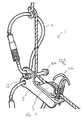
- Figure 1 schematically shows a first device 1 for use in explaining the invention.
- the device 1 comprises a base plate 3 to which various components are attached.
- a rope trapping arrangement 5 is attached to a centre portion of the plate 3.
- the rope trapping arrangement 5 comprises an elongate block having a deep tapered groove formed therein.
- the surface of the groove is formed with a number of parallel ridges extending at an oblique angle to the groove.
- the groove is parallel to the major edges of the plate 3.
- the rope trapping arrangement 5 is operable so that a suitably sized rope received into the groove is trapped.
- a rope When a rope is trapped in this way, it cannot be moved through the groove in the forwards direction of the arrow 7.
- a tension on the rope in the forwards direction causes the rope to be guided by the oblique ridges deeper into the tapered groove.
- a rope guiding arrangement is also attached to the plate 3.
- the rope guiding arrangement comprises of a pair of hooks 11 a and lateral bar 11 b provided at rearward and forward ends of the rope trapping arrangement 5.
- the purpose of the rope guiding arrangement is to control the route take by a rope through the device 1.
- the pair of hooks 11a, and the bar 11b, define an enclosed space through which the rope is guided in a direction parallel to the rope trapping arrangement 5.
- the hooks of the pair 11a are separated in the longitudinal direction of the rope by a small distance, which distance is approximately the width of the rope. This allows the rope to be inserted into the spaces defined by the hooks 11a, without having to thread an end of the rope through the space. Once the rope is inserted and correctly orientated, it cannot pass back between the hooks 11a.
- the pair of hooks 11a, and the bar 11b define a route for the rope through the device that is substantially parallel to the rope trapping arrangement 5.
- the pair of hooks 11a in particular, guide the rope so that it is prevented from moving to the sides of the rope trapping arrangement 5, i.e. in a lateral direction.
- the hooks 11a do, however, allow movement of the rope into and out of the rope trapping arrangement 5 in a transverse direction.
- a friction providing device 9 is also attached to the plate 3, positioned at the forward end of the rope trapping arrangement 5.
- the friction providing device 9 is a karabiner attached to the plate 3 by a hole formed therein.
- Karabiners are well known to those skilled in the art.
- a karabiner generally comprises a large oval or D-shaped metal ring with a spring loaded or lockable clip that allows it to be attached to ropes and other lifting equipment.
- the metal ring of the karabiner provides a bar about which the rope may be looped or knotted.
- the plate 3 of the device 1 also has a hole 13 formed therein. This hole 13 is provided for use in attaching the device 1 to a fixed structure, for example using another karabiner.
- the position of the holes for the friction providing device 9 and the hole 13 are situated in a vertical plane, and the plate is situated on the horizontal plane, as shown in Figure 1 .
- the device 1 is attached to a fixed structure, such as the base structure of a pylon that carries power transmission lines, using the attachment hole 13 and a karabiner.
- a rope connected to a load to be suspended is passed through a suspended pulley arrangement, and the free end is dropped to the ground.
- the free end of the rope is then guided through the device 1 by knotting it around the friction providing device 9 and inserting it between the pairs of hooks 11.
- the rope is knotted around the friction providing device 9 using an Italian hitch, which will be well known to those skilled in the art.
- the tension in the rope at this stage causes the device 1 to assume an orientation in which the axis of the groove in the rope trapping arrangement 5 is substantially vertical.
- the operator When it is desired to lower a load to the ground, the operator is required to pay out the rope in a controlled manner.
- the rope is paid out towards the device 1 from a horizontal, transverse direction, since the device 1 is positioned at or near the ground level. Because of the orientation of the device 1, and the direction from which rope is paid out by the operator, the rope does not engage with the rope trapping arrangement 5. Instead, the rope is offset in the transverse direction from the rope trapping arrangement 5, as allowed by the pairs of hooks 11 a and the bar 11 b.
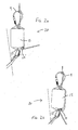
- Figures 2a and 2b show a device 20 according to the invention in first and second positions respectively.
- the device 20 shown in these Figures is similar to the device shown in Figure 1 , and the same reference signs are used for functionally similar features.
- the rope trapping arrangement is housed in a casing 15, and cannot therefore be seen.
- the rope trapping arrangement of the device 20 only differs from that of the device 1 in its positioning: its groove faces the sideways direction.
- the pairs of hooks of the device 20 are also concealed by the casing 15. The hooks differ from those of the device 1 in that they only allow the rope to move within the device 20 in the sideways direction.
- the friction providing device 9 and the attachment hole 13 of the device 20 are the same as those described with reference to the device 1.
- the device 20 is provided with a rotatable grooved wheel 17 mounted on the end of a sideways pivotable arm (not shown) at the rearward end of the rope trapping arrangement.
- the pivotable arm is biased by a spring (not shown) towards the rope trapping arrangement within the casing 15.
- the device 20 is used in a similar way as the device 1, except that rope is paid out from a horizontal, sideways direction.
- the device 20 does not rely on gravity to cause the rope to engage with the rope trapping arrangement when it is dropped by the operator. Instead, the spring biasing of the pivotal arm causes the grooved wheel 17 to urge against the rope so that it engages with the rope trapping arrangement.
- the strength of the spring is strong enough to urge a released rope into the rope trapping arrangement, but not so strong that the rope cannot be disengaged from the arrangement by manually pulling.
- Figure 2a shows the device 20 in the normal mode of operation when an operator is paying out rope from a horizontal, sideways direction. In this mode of operation, the rope passes through the device 20 so that the load is gradually lowered.
- Figure 2b shows the device 20 in the locked off mode of operation where an operator has released the rope, and the grooved wheel has urged the rope into the rope trapping arrangement.
- the rope trapping arrangement prevents any movement of the rope through the device until a sideways and backwards tension is applied to the rope by the operator, thereby freeing the rope for the rope trapping arrangement.
- Figure 3 shows the device 20 being used by an operator to lower a load suspended from a pylon used to support power transmission lines. As can be seen, use of the device prevents a dangerous situation from arising when the rope is accidentally released.
Landscapes
- Engineering & Computer Science (AREA)
- Mechanical Engineering (AREA)
- Health & Medical Sciences (AREA)
- General Health & Medical Sciences (AREA)
- Business, Economics & Management (AREA)
- Emergency Management (AREA)
- Emergency Lowering Means (AREA)
- Lift-Guide Devices, And Elevator Ropes And Cables (AREA)
- Catching Or Destruction (AREA)
- Vehicle Body Suspensions (AREA)
Abstract
Description
- This invention relates to a device for use, for example, in lowering loads that are supported by a rope. In particular, this invention relates to a device that may be used for manually lowering loads that are supported by a rope and pulley arrangement. Throughout this disclosure, the term "rope" is intended to mean any flexible elongate element suitable for transmitting forces. Thus, the term "rope" is to be taken, for example, to include cables and straps.
- It is well known to in the art to manually lower a load between two vertically offset levels using a rope and pulley arrangement. The pulley is fixedly attached to a supporting structure positioned above the two levels. The rope is attached to the load and guided through the pulley, and the rope is then manually paid out under the control of an operator.
- It is also known in the art to improve the ergonomics of the above described rope and pulley arrangement by threading the rope through a pulley or loop that is fixedly attached to a supporting structure positioned at the level of the operator. The operator is then able to pay out the rope in a substantially horizontal direction, which is preferable to paying out in the vertical direction.
- A problem associated with the above described arrangement arises when lowering the load by manually paying out the rope. In particular, if the operator releases the rope for any reason, a dangerous situation results because the load may fall freely to the ground. It is known to increase friction in the arrangement by looping the rope through known devices, and this increased friction to some degree allows for fluctuations in the support on the rope provided by the operator. For example the rope may be tied in an "Italian hitch" around a karabiner. However, increased friction alone cannot accommodate situations in which the rope is completely released by the operator without a risk of the load falling freely.
-
WO 02/055425 - According to the invention, there is provided a device for use in paying out a rope using the force from a load supported by the rope, the device comprising: a rope trapping arrangement including an element having a groove for receiving the rope; and a rope guiding arrangement defining a channel such that the rope is able to move transversely within the channel, the channel having a first guided position in which the rope is out of the rope trapping arrangement, and a second guided position in which the rope is engaged into the rope trapping arrangement, wherein the rope guiding arrangement is adapted to guide the rope to the second guided position under the action of a resilient element, and wherein the device is operable in two modes: a first mode in which the rope is held by an operator of the device in the first guided position and the rope can be paid out; and a second mode in which the rope is released by an operator of the device, and the rope is guided transversely to the second guided position, thereby to trap the rope and prevent further paying out of the rope, wherein the device is characterised in that the groove of the rope trapping arrangement is tapered and formed with parallel ridges extending at an oblique angle to the groove for trapping the rope.
- The invention provides a device which allows an operator to pay out a rope in a safe and controlled manner, and using the force from a load supported by the rope. In particular, when the rope is held by the operator, it is in the first guided position and is not trapped by the rope trapping arrangement. However, if the rope is released by the operator, for example because he slips, the rope is safely guided into the second guided position and becomes trapped by the rope trapping arrangement. In this way, the risk of the load falling freely when the rope is released is minimised.
- In a preferred embodiment, the device further comprises a friction providing arrangement for controlling paying out of the rope. The friction providing arrangement may be positioned at one end of the rope trapping arrangement. In a particularly preferred arrangement, the friction providing arrangement comprises a bar about which the rope is knotted. The bar may, for example, be provided as a karabiner and the knot may, for example, be an Italian hitch.
- As described above, the rope guiding arrangement is adapted to guide the rope to the second guiding position under the action of a resilient element. For example, the rope guiding arrangement may again define a channel, with the rope moving transversely within the channel, and wherein an element such as a resiliently biased guide wheel urges the rope towards the second guiding position.
- The invention also provides a support arrangement comprising: a rope; and a device as described above, wherein the rope is guided through the rope guiding arrangement. The rope is preferably formed from a large number of twisted and intertwined fibres, although other types of rope may be suitable.
- In the arrangement, the rope is preferably knotted using an Italian hitch about a bar, to allow control of the paying out of the rope.
- According to another aspect of the invention, there is provided a method of paying out a rope using the force from a load supported by the rope, the method comprising: guiding the rope through a device having a rope trapping arrangement and a rope guiding arrangement, the rope trapping arrangement including an element having a groove for receiving the rope, the rope guiding arrangement defining a channel such that the rope is able to move transversely within the channel, the device being attached to a fixed structure; holding the rope so that it is maintained in a first guided position in which the rope is out of the rope trapping arrangement, and paying out the rope; and releasing the rope, so that it is guided transversely under the action of a resilient element to a second guided position in which the rope is engaged into the rope trapping arrangement, thereby trapping the rope and preventing further paying out of the rope, wherein the method is characterised in that the groove of the rope trapping arrangement is tapered and formed with parallel ridges extending at an oblique angle to the groove for trapping the rope.
- Embodiments of the invention will now be described, purely by way of example, with reference to the accompanying drawings, in which:
-
Figure 1 schematically shows a first device for use in explaining the invention; -
Figures 2a and 2b shows a device according to the invention in first and second positions respectively; and -
Figure 3 shows the device ofFigure 2 being used to pay out a rope using the force from a load supported by the rope. - The invention provides a device and method for use in paying out a rope using the force from a load supported by the rope. The rope is guided through a rope guiding arrangement as it is paid out by an operator. If the rope is released by the operator, for example because he slips, it is guided into a rope trapping arrangement which traps the rope and prevents any further rope from being paid out.
-
Figure 1 schematically shows a first device 1 for use in explaining the invention. The device 1 comprises abase plate 3 to which various components are attached. - A
rope trapping arrangement 5 is attached to a centre portion of theplate 3. Therope trapping arrangement 5 comprises an elongate block having a deep tapered groove formed therein. The surface of the groove is formed with a number of parallel ridges extending at an oblique angle to the groove. The groove is parallel to the major edges of theplate 3. - The
rope trapping arrangement 5 is operable so that a suitably sized rope received into the groove is trapped. When a rope is trapped in this way, it cannot be moved through the groove in the forwards direction of the arrow 7. In particular, a tension on the rope in the forwards direction causes the rope to be guided by the oblique ridges deeper into the tapered groove. - When the rope is trapped, it can nevertheless still be moved in the backwards direction. In particular, a tension on the rope in the backwards direction causes the rope to be guided by the oblique ridges in a transverse direction out of the tapered groove. The rope can also be disengaged from the
rope trapping arrangement 5 by pulling the rope in a transverse direction. - A rope guiding arrangement is also attached to the
plate 3. The rope guiding arrangement comprises of a pair of hooks 11 a and lateral bar 11 b provided at rearward and forward ends of therope trapping arrangement 5. The purpose of the rope guiding arrangement is to control the route take by a rope through the device 1. - The pair of hooks 11a, and the bar 11b, define an enclosed space through which the rope is guided in a direction parallel to the
rope trapping arrangement 5. The hooks of the pair 11a are separated in the longitudinal direction of the rope by a small distance, which distance is approximately the width of the rope. This allows the rope to be inserted into the spaces defined by the hooks 11a, without having to thread an end of the rope through the space. Once the rope is inserted and correctly orientated, it cannot pass back between the hooks 11a. - The pair of hooks 11a, and the bar 11b define a route for the rope through the device that is substantially parallel to the
rope trapping arrangement 5. The pair of hooks 11a, in particular, guide the rope so that it is prevented from moving to the sides of therope trapping arrangement 5, i.e. in a lateral direction. The hooks 11a do, however, allow movement of the rope into and out of therope trapping arrangement 5 in a transverse direction. - A
friction providing device 9 is also attached to theplate 3, positioned at the forward end of therope trapping arrangement 5. Thefriction providing device 9 is a karabiner attached to theplate 3 by a hole formed therein. Karabiners are well known to those skilled in the art. A karabiner generally comprises a large oval or D-shaped metal ring with a spring loaded or lockable clip that allows it to be attached to ropes and other lifting equipment. The metal ring of the karabiner provides a bar about which the rope may be looped or knotted. - The
plate 3 of the device 1 also has ahole 13 formed therein. Thishole 13 is provided for use in attaching the device 1 to a fixed structure, for example using another karabiner. - The position of the holes for the
friction providing device 9 and thehole 13 are situated in a vertical plane, and the plate is situated on the horizontal plane, as shown inFigure 1 . - In use, the device 1 is attached to a fixed structure, such as the base structure of a pylon that carries power transmission lines, using the
attachment hole 13 and a karabiner. A rope connected to a load to be suspended is passed through a suspended pulley arrangement, and the free end is dropped to the ground. The free end of the rope is then guided through the device 1 by knotting it around thefriction providing device 9 and inserting it between the pairs of hooks 11. The rope is knotted around thefriction providing device 9 using an Italian hitch, which will be well known to those skilled in the art. - The tension in the rope at this stage causes the device 1 to assume an orientation in which the axis of the groove in the
rope trapping arrangement 5 is substantially vertical. - When it is desired to lower a load to the ground, the operator is required to pay out the rope in a controlled manner. The rope is paid out towards the device 1 from a horizontal, transverse direction, since the device 1 is positioned at or near the ground level. Because of the orientation of the device 1, and the direction from which rope is paid out by the operator, the rope does not engage with the
rope trapping arrangement 5. Instead, the rope is offset in the transverse direction from therope trapping arrangement 5, as allowed by the pairs of hooks 11 a and the bar 11 b. - However, if the operator drops the rope, for example because he slips, the free end of the rope then falls under the action of gravity. As the rope falls, it moves in the transverse direction within the device 1, and becomes engaged with the
rope trapping arrangement 5. In this way, a dangerous situation in which the load falls freely is avoided. Thefriction providing device 9 allows the rope to be paid out smoothly. -
Figures 2a and 2b show adevice 20 according to the invention in first and second positions respectively. Thedevice 20 shown in these Figures is similar to the device shown inFigure 1 , and the same reference signs are used for functionally similar features. - In the
device 20, the rope trapping arrangement is housed in acasing 15, and cannot therefore be seen. The rope trapping arrangement of thedevice 20 only differs from that of the device 1 in its positioning: its groove faces the sideways direction. The pairs of hooks of thedevice 20 are also concealed by thecasing 15. The hooks differ from those of the device 1 in that they only allow the rope to move within thedevice 20 in the sideways direction. - The
friction providing device 9 and theattachment hole 13 of thedevice 20 are the same as those described with reference to the device 1. - The
device 20 is provided with a rotatablegrooved wheel 17 mounted on the end of a sideways pivotable arm (not shown) at the rearward end of the rope trapping arrangement. The pivotable arm is biased by a spring (not shown) towards the rope trapping arrangement within thecasing 15. - The
device 20 is used in a similar way as the device 1, except that rope is paid out from a horizontal, sideways direction. - Additionally, the
device 20 does not rely on gravity to cause the rope to engage with the rope trapping arrangement when it is dropped by the operator. Instead, the spring biasing of the pivotal arm causes thegrooved wheel 17 to urge against the rope so that it engages with the rope trapping arrangement. The strength of the spring is strong enough to urge a released rope into the rope trapping arrangement, but not so strong that the rope cannot be disengaged from the arrangement by manually pulling. - In the Figures,
Figure 2a shows thedevice 20 in the normal mode of operation when an operator is paying out rope from a horizontal, sideways direction. In this mode of operation, the rope passes through thedevice 20 so that the load is gradually lowered. -
Figure 2b shows thedevice 20 in the locked off mode of operation where an operator has released the rope, and the grooved wheel has urged the rope into the rope trapping arrangement. In this mode, the rope trapping arrangement prevents any movement of the rope through the device until a sideways and backwards tension is applied to the rope by the operator, thereby freeing the rope for the rope trapping arrangement. -
Figure 3 shows thedevice 20 being used by an operator to lower a load suspended from a pylon used to support power transmission lines. As can be seen, use of the device prevents a dangerous situation from arising when the rope is accidentally released. - Specific embodiments of the invention have been described. However, the skilled person will understand that various changes and modifications may be made to the described devices without departing from the invention, as defined by the claims.
- Use of the devices is described as involving knotting the rope around the friction providing device using an Italian hitch. However, other knots may be suitable, and the knot and even the friction providing device may be dispensed with.
Claims (6)
- A device for use in paying out a rope using the force from a load supported by the rope, the device comprising:a rope trapping arrangement (5) including an element having a groove for receiving the rope; anda rope guiding arrangement (17) defining a channel such that the rope is able to move transversely within the channel, the channel having a first guided position in which the rope is out of the rope trapping arrangement, and a second guided position in which the rope is engaged into the rope trapping arrangement,wherein the rope guiding arrangement (17) is adapted to guide the rope to the second guided position under the action of a resilient element,and wherein the device is operable in two modes:a first mode in which the rope is held by an operator of the device in the first guided position and the rope can be paid out; anda second mode in which the rope is released by an operator of the device, and the rope is guided transversely to the second guided position, thereby to trap the rope and prevent further paying out of the rope,wherein the device is characterised in that the groove of the rope trapping arrangement (5) is tapered and formed with parallel ridges extending at an oblique angle to the groove for trapping the rope.
- A device as claimed in claim 1, wherein the device further comprises a friction providing arrangement (9) for controlling paying out of the rope.
- A device as claimed in claim 2, wherein the friction providing arrangement (9) comprises a bar about which the rope is knotted.
- A support arrangement comprising:a rope; anda device as claimed in any preceding claim,wherein the rope is guided through the rope guiding arrangement (17).
- An arrangement as claimed in claim 4, wherein the rope is knotted using an Italian hitch about a bar (9), to allow control of the paying out of the rope.
- A method of paying out a rope using the force from a load supported by the rope, the method comprising:guiding the rope through a device (20) having a rope trapping arrangement (5) and a rope guiding arrangement (17), the rope trapping arrangement including an element having a groove for receiving the rope, the rope guiding arrangement (17) defining a channel such that the rope is able to move transversely within the channel, the device (20) being attached to a fixed structure;holding the rope so that it is maintained in a first guided position in which the rope is out of the rope trapping arrangement (5), and paying out the rope; andreleasing the rope, so that it is guided transversely under the action of a resilient element to a second guided position in which the rope is engaged into the rope trapping arrangement (5), thereby trapping the rope and preventing further paying out of the rope,wherein the method is characterised in that the groove of the rope trapping arrangement (5) is tapered and formed with parallel ridges extending at an oblique angle to the groove for trapping the rope.
Applications Claiming Priority (1)
| Application Number | Priority Date | Filing Date | Title |
|---|---|---|---|
| GB0522414A GB2431907B (en) | 2005-11-02 | 2005-11-02 | Device for use in lowering loads |
Publications (3)
| Publication Number | Publication Date |
|---|---|
| EP1783091A2 EP1783091A2 (en) | 2007-05-09 |
| EP1783091A3 EP1783091A3 (en) | 2008-05-28 |
| EP1783091B1 true EP1783091B1 (en) | 2011-09-14 |
Family
ID=35516251
Family Applications (1)
| Application Number | Title | Priority Date | Filing Date |
|---|---|---|---|
| EP06122589A Not-in-force EP1783091B1 (en) | 2005-11-02 | 2006-10-19 | Device operating on ropes for use in lowering loads |
Country Status (3)
| Country | Link |
|---|---|
| EP (1) | EP1783091B1 (en) |
| AT (1) | ATE524408T1 (en) |
| GB (1) | GB2431907B (en) |
Families Citing this family (2)
| Publication number | Priority date | Publication date | Assignee | Title |
|---|---|---|---|---|
| IT1403897B1 (en) * | 2010-12-30 | 2013-11-08 | Nube S R L | CRAFT FOR NAUTICAL USE |
| CN202575839U (en) * | 2012-01-19 | 2012-12-05 | 何少敦 | Suspension descent system |
Family Cites Families (6)
| Publication number | Priority date | Publication date | Assignee | Title |
|---|---|---|---|---|
| FR2505309B1 (en) * | 1981-05-08 | 1985-10-25 | Games | DEVICE FOR BRAKING AND / OR IMMOBILIZING A LOAD, IN PARTICULAR A FALL PROTECTION DEVICE |
| GB9808879D0 (en) * | 1998-04-28 | 1998-06-24 | Renton Julian E | Cleat |
| DK0968737T3 (en) * | 1998-07-02 | 2008-09-01 | Tornomeccanica S R L | Pulley with automatic safety brake system |
| FR2804421B1 (en) * | 2000-01-28 | 2002-03-22 | Jean Pierre Michel Verrier | LOCK-UNLOCKER WITH BRAKE REGULATION REMOTELY CONTROLLED BY A SINGLE END |
| US6685171B2 (en) * | 2001-01-10 | 2004-02-03 | Harken, Inc. | Lifting device |
| US6722303B2 (en) * | 2002-08-20 | 2004-04-20 | Harken, Inc. | Fairlead and cam assembly |
-
2005
- 2005-11-02 GB GB0522414A patent/GB2431907B/en not_active Expired - Fee Related
-
2006
- 2006-10-19 AT AT06122589T patent/ATE524408T1/en not_active IP Right Cessation
- 2006-10-19 EP EP06122589A patent/EP1783091B1/en not_active Not-in-force
Also Published As
| Publication number | Publication date |
|---|---|
| GB2431907B (en) | 2009-04-15 |
| EP1783091A2 (en) | 2007-05-09 |
| ATE524408T1 (en) | 2011-09-15 |
| GB0522414D0 (en) | 2005-12-14 |
| EP1783091A3 (en) | 2008-05-28 |
| GB2431907A (en) | 2007-05-09 |
Similar Documents
| Publication | Publication Date | Title |
|---|---|---|
| US7963366B2 (en) | Split tube belay device | |
| US12157019B2 (en) | Shuttle for a climbing protection system | |
| US8225905B2 (en) | Ascender device with cam for belaying on a fixed rope | |
| EP3797202B1 (en) | Fall control ladder | |
| US5165499A (en) | Anchor system for use with fall prevention safety devices | |
| EP2796172B1 (en) | Fall arrest device | |
| US20150266454A1 (en) | Cable-traversing trolley adapted for use with impact braking | |
| US20080245611A1 (en) | Self-Belay And Rappel Device And Methods Of Use | |
| US20100213004A1 (en) | Pole safety assembly | |
| US7500290B2 (en) | Simple climber's multi-tool | |
| CA3067258A1 (en) | Safety carabiner to be placed on a rope | |
| US10619417B2 (en) | Pass-through cable grab system | |
| US10730535B2 (en) | Emergency arrest device for zip line | |
| EP1783091A2 (en) | Device operating on ropes for use in lowering loads | |
| US8511438B1 (en) | Lifting and lowering device and system | |
| JP4420802B2 (en) | How to prevent fall of tree work | |
| GB2416386A (en) | Rope clamping device | |
| US10787347B1 (en) | Self-locking pulley | |
| US5150766A (en) | Sliding anchor system and method of use | |
| US20080011543A1 (en) | Simple Climber's Multi-Tool | |
| CA2511460C (en) | Apparatus for moving elevator equipment | |
| EP1621506B1 (en) | Apparatus for moving elevator equipment | |
| EP2883574B1 (en) | Belay device | |
| GB2421234A (en) | Rescue System | |
| US12582875B1 (en) | Climbing device |
Legal Events
| Date | Code | Title | Description |
|---|---|---|---|
| PUAI | Public reference made under article 153(3) epc to a published international application that has entered the european phase |
Free format text: ORIGINAL CODE: 0009012 |
|
| AK | Designated contracting states |
Kind code of ref document: A2 Designated state(s): AT BE BG CH CY CZ DE DK EE ES FI FR GB GR HU IE IS IT LI LT LU LV MC NL PL PT RO SE SI SK TR |
|
| AX | Request for extension of the european patent |
Extension state: AL BA HR MK YU |
|
| PUAL | Search report despatched |
Free format text: ORIGINAL CODE: 0009013 |
|
| AK | Designated contracting states |
Kind code of ref document: A3 Designated state(s): AT BE BG CH CY CZ DE DK EE ES FI FR GB GR HU IE IS IT LI LT LU LV MC NL PL PT RO SE SI SK TR |
|
| AX | Request for extension of the european patent |
Extension state: AL BA HR MK RS |
|
| 17P | Request for examination filed |
Effective date: 20081001 |
|
| 17Q | First examination report despatched |
Effective date: 20081104 |
|
| AKX | Designation fees paid |
Designated state(s): AT BE BG CH CY CZ DE DK EE ES FI FR GB GR HU IE IS IT LI LT LU LV MC NL PL PT RO SE SI SK TR |
|
| GRAP | Despatch of communication of intention to grant a patent |
Free format text: ORIGINAL CODE: EPIDOSNIGR1 |
|
| GRAS | Grant fee paid |
Free format text: ORIGINAL CODE: EPIDOSNIGR3 |
|
| GRAA | (expected) grant |
Free format text: ORIGINAL CODE: 0009210 |
|
| AK | Designated contracting states |
Kind code of ref document: B1 Designated state(s): AT BE BG CH CY CZ DE DK EE ES FI FR GB GR HU IE IS IT LI LT LU LV MC NL PL PT RO SE SI SK TR |
|
| REG | Reference to a national code |
Ref country code: CH Ref legal event code: EP |
|
| REG | Reference to a national code |
Ref country code: IE Ref legal event code: FG4D |
|
| REG | Reference to a national code |
Ref country code: DE Ref legal event code: R096 Ref document number: 602006024346 Country of ref document: DE Effective date: 20111208 |
|
| REG | Reference to a national code |
Ref country code: NL Ref legal event code: VDEP Effective date: 20110914 |
|
| PG25 | Lapsed in a contracting state [announced via postgrant information from national office to epo] |
Ref country code: SE Free format text: LAPSE BECAUSE OF FAILURE TO SUBMIT A TRANSLATION OF THE DESCRIPTION OR TO PAY THE FEE WITHIN THE PRESCRIBED TIME-LIMIT Effective date: 20110914 Ref country code: LT Free format text: LAPSE BECAUSE OF FAILURE TO SUBMIT A TRANSLATION OF THE DESCRIPTION OR TO PAY THE FEE WITHIN THE PRESCRIBED TIME-LIMIT Effective date: 20110914 Ref country code: FI Free format text: LAPSE BECAUSE OF FAILURE TO SUBMIT A TRANSLATION OF THE DESCRIPTION OR TO PAY THE FEE WITHIN THE PRESCRIBED TIME-LIMIT Effective date: 20110914 |
|
| LTIE | Lt: invalidation of european patent or patent extension |
Effective date: 20110914 |
|
| PG25 | Lapsed in a contracting state [announced via postgrant information from national office to epo] |
Ref country code: SI Free format text: LAPSE BECAUSE OF FAILURE TO SUBMIT A TRANSLATION OF THE DESCRIPTION OR TO PAY THE FEE WITHIN THE PRESCRIBED TIME-LIMIT Effective date: 20110914 Ref country code: AT Free format text: LAPSE BECAUSE OF FAILURE TO SUBMIT A TRANSLATION OF THE DESCRIPTION OR TO PAY THE FEE WITHIN THE PRESCRIBED TIME-LIMIT Effective date: 20110914 Ref country code: CY Free format text: LAPSE BECAUSE OF FAILURE TO SUBMIT A TRANSLATION OF THE DESCRIPTION OR TO PAY THE FEE WITHIN THE PRESCRIBED TIME-LIMIT Effective date: 20110914 Ref country code: LV Free format text: LAPSE BECAUSE OF FAILURE TO SUBMIT A TRANSLATION OF THE DESCRIPTION OR TO PAY THE FEE WITHIN THE PRESCRIBED TIME-LIMIT Effective date: 20110914 Ref country code: GR Free format text: LAPSE BECAUSE OF FAILURE TO SUBMIT A TRANSLATION OF THE DESCRIPTION OR TO PAY THE FEE WITHIN THE PRESCRIBED TIME-LIMIT Effective date: 20111215 |
|
| REG | Reference to a national code |
Ref country code: AT Ref legal event code: MK05 Ref document number: 524408 Country of ref document: AT Kind code of ref document: T Effective date: 20110914 |
|
| PG25 | Lapsed in a contracting state [announced via postgrant information from national office to epo] |
Ref country code: BE Free format text: LAPSE BECAUSE OF FAILURE TO SUBMIT A TRANSLATION OF THE DESCRIPTION OR TO PAY THE FEE WITHIN THE PRESCRIBED TIME-LIMIT Effective date: 20110914 |
|
| PG25 | Lapsed in a contracting state [announced via postgrant information from national office to epo] |
Ref country code: CZ Free format text: LAPSE BECAUSE OF FAILURE TO SUBMIT A TRANSLATION OF THE DESCRIPTION OR TO PAY THE FEE WITHIN THE PRESCRIBED TIME-LIMIT Effective date: 20110914 Ref country code: IS Free format text: LAPSE BECAUSE OF FAILURE TO SUBMIT A TRANSLATION OF THE DESCRIPTION OR TO PAY THE FEE WITHIN THE PRESCRIBED TIME-LIMIT Effective date: 20120114 Ref country code: SK Free format text: LAPSE BECAUSE OF FAILURE TO SUBMIT A TRANSLATION OF THE DESCRIPTION OR TO PAY THE FEE WITHIN THE PRESCRIBED TIME-LIMIT Effective date: 20110914 |
|
| PG25 | Lapsed in a contracting state [announced via postgrant information from national office to epo] |
Ref country code: MC Free format text: LAPSE BECAUSE OF NON-PAYMENT OF DUE FEES Effective date: 20111031 Ref country code: IT Free format text: LAPSE BECAUSE OF FAILURE TO SUBMIT A TRANSLATION OF THE DESCRIPTION OR TO PAY THE FEE WITHIN THE PRESCRIBED TIME-LIMIT Effective date: 20110914 Ref country code: EE Free format text: LAPSE BECAUSE OF FAILURE TO SUBMIT A TRANSLATION OF THE DESCRIPTION OR TO PAY THE FEE WITHIN THE PRESCRIBED TIME-LIMIT Effective date: 20110914 Ref country code: NL Free format text: LAPSE BECAUSE OF FAILURE TO SUBMIT A TRANSLATION OF THE DESCRIPTION OR TO PAY THE FEE WITHIN THE PRESCRIBED TIME-LIMIT Effective date: 20110914 Ref country code: PL Free format text: LAPSE BECAUSE OF FAILURE TO SUBMIT A TRANSLATION OF THE DESCRIPTION OR TO PAY THE FEE WITHIN THE PRESCRIBED TIME-LIMIT Effective date: 20110914 Ref country code: PT Free format text: LAPSE BECAUSE OF FAILURE TO SUBMIT A TRANSLATION OF THE DESCRIPTION OR TO PAY THE FEE WITHIN THE PRESCRIBED TIME-LIMIT Effective date: 20120116 Ref country code: RO Free format text: LAPSE BECAUSE OF FAILURE TO SUBMIT A TRANSLATION OF THE DESCRIPTION OR TO PAY THE FEE WITHIN THE PRESCRIBED TIME-LIMIT Effective date: 20110914 |
|
| REG | Reference to a national code |
Ref country code: CH Ref legal event code: PL |
|
| PLBE | No opposition filed within time limit |
Free format text: ORIGINAL CODE: 0009261 |
|
| REG | Reference to a national code |
Ref country code: FR Ref legal event code: ST Effective date: 20120629 |
|
| STAA | Information on the status of an ep patent application or granted ep patent |
Free format text: STATUS: NO OPPOSITION FILED WITHIN TIME LIMIT |
|
| PG25 | Lapsed in a contracting state [announced via postgrant information from national office to epo] |
Ref country code: LI Free format text: LAPSE BECAUSE OF NON-PAYMENT OF DUE FEES Effective date: 20111031 Ref country code: DE Free format text: LAPSE BECAUSE OF NON-PAYMENT OF DUE FEES Effective date: 20120501 Ref country code: DK Free format text: LAPSE BECAUSE OF FAILURE TO SUBMIT A TRANSLATION OF THE DESCRIPTION OR TO PAY THE FEE WITHIN THE PRESCRIBED TIME-LIMIT Effective date: 20110914 Ref country code: CH Free format text: LAPSE BECAUSE OF NON-PAYMENT OF DUE FEES Effective date: 20111031 |
|
| REG | Reference to a national code |
Ref country code: IE Ref legal event code: MM4A |
|
| REG | Reference to a national code |
Ref country code: DE Ref legal event code: R119 Ref document number: 602006024346 Country of ref document: DE Effective date: 20120501 |
|
| 26N | No opposition filed |
Effective date: 20120615 |
|
| GBPC | Gb: european patent ceased through non-payment of renewal fee |
Effective date: 20111214 |
|
| PG25 | Lapsed in a contracting state [announced via postgrant information from national office to epo] |
Ref country code: FR Free format text: LAPSE BECAUSE OF NON-PAYMENT OF DUE FEES Effective date: 20111114 |
|
| PG25 | Lapsed in a contracting state [announced via postgrant information from national office to epo] |
Ref country code: IE Free format text: LAPSE BECAUSE OF NON-PAYMENT OF DUE FEES Effective date: 20111019 Ref country code: GB Free format text: LAPSE BECAUSE OF NON-PAYMENT OF DUE FEES Effective date: 20111214 |
|
| PG25 | Lapsed in a contracting state [announced via postgrant information from national office to epo] |
Ref country code: ES Free format text: LAPSE BECAUSE OF FAILURE TO SUBMIT A TRANSLATION OF THE DESCRIPTION OR TO PAY THE FEE WITHIN THE PRESCRIBED TIME-LIMIT Effective date: 20111225 |
|
| PG25 | Lapsed in a contracting state [announced via postgrant information from national office to epo] |
Ref country code: LU Free format text: LAPSE BECAUSE OF NON-PAYMENT OF DUE FEES Effective date: 20111019 |
|
| PG25 | Lapsed in a contracting state [announced via postgrant information from national office to epo] |
Ref country code: BG Free format text: LAPSE BECAUSE OF FAILURE TO SUBMIT A TRANSLATION OF THE DESCRIPTION OR TO PAY THE FEE WITHIN THE PRESCRIBED TIME-LIMIT Effective date: 20111214 |
|
| PG25 | Lapsed in a contracting state [announced via postgrant information from national office to epo] |
Ref country code: TR Free format text: LAPSE BECAUSE OF FAILURE TO SUBMIT A TRANSLATION OF THE DESCRIPTION OR TO PAY THE FEE WITHIN THE PRESCRIBED TIME-LIMIT Effective date: 20110914 |
|
| PG25 | Lapsed in a contracting state [announced via postgrant information from national office to epo] |
Ref country code: HU Free format text: LAPSE BECAUSE OF FAILURE TO SUBMIT A TRANSLATION OF THE DESCRIPTION OR TO PAY THE FEE WITHIN THE PRESCRIBED TIME-LIMIT Effective date: 20110914 |