EP1782928A1 - An industrial robot system with more than one TPU - Google Patents
An industrial robot system with more than one TPU Download PDFInfo
- Publication number
- EP1782928A1 EP1782928A1 EP05110485A EP05110485A EP1782928A1 EP 1782928 A1 EP1782928 A1 EP 1782928A1 EP 05110485 A EP05110485 A EP 05110485A EP 05110485 A EP05110485 A EP 05110485A EP 1782928 A1 EP1782928 A1 EP 1782928A1
- Authority
- EP
- European Patent Office
- Prior art keywords
- tpu
- master
- authority
- robot
- control unit
- Prior art date
- Legal status (The legal status is an assumption and is not a legal conclusion. Google has not performed a legal analysis and makes no representation as to the accuracy of the status listed.)
- Granted
Links
- 230000033001 locomotion Effects 0.000 claims abstract description 27
- 230000004913 activation Effects 0.000 claims abstract description 5
- 238000000034 method Methods 0.000 claims description 35
- 238000004590 computer program Methods 0.000 claims description 4
- 230000006870 function Effects 0.000 description 15
- 239000011159 matrix material Substances 0.000 description 13
- 238000010586 diagram Methods 0.000 description 8
- 238000004891 communication Methods 0.000 description 6
- 230000003213 activating effect Effects 0.000 description 4
- 238000013475 authorization Methods 0.000 description 2
- 238000012545 processing Methods 0.000 description 2
- 208000027418 Wounds and injury Diseases 0.000 description 1
- 238000012790 confirmation Methods 0.000 description 1
- 230000008878 coupling Effects 0.000 description 1
- 238000010168 coupling process Methods 0.000 description 1
- 238000005859 coupling reaction Methods 0.000 description 1
- 230000006378 damage Effects 0.000 description 1
- 208000014674 injury Diseases 0.000 description 1
- 238000009434 installation Methods 0.000 description 1
- 238000012544 monitoring process Methods 0.000 description 1
- 238000012360 testing method Methods 0.000 description 1
- 230000000007 visual effect Effects 0.000 description 1
Images



Classifications
-
- B—PERFORMING OPERATIONS; TRANSPORTING
- B25—HAND TOOLS; PORTABLE POWER-DRIVEN TOOLS; MANIPULATORS
- B25J—MANIPULATORS; CHAMBERS PROVIDED WITH MANIPULATION DEVICES
- B25J13/00—Controls for manipulators
- B25J13/06—Control stands, e.g. consoles, switchboards
-
- B—PERFORMING OPERATIONS; TRANSPORTING
- B25—HAND TOOLS; PORTABLE POWER-DRIVEN TOOLS; MANIPULATORS
- B25J—MANIPULATORS; CHAMBERS PROVIDED WITH MANIPULATION DEVICES
- B25J19/00—Accessories fitted to manipulators, e.g. for monitoring, for viewing; Safety devices combined with or specially adapted for use in connection with manipulators
- B25J19/06—Safety devices
Definitions
- the present invention relates to an industrial robot system including an industrial robot comprising at least one manipulator and a control unit for controlling the manipulator, and at least two portable operator control devices, called TPU:s.
- the invention also relates to a method for controlling such a robot system.
- the person controlling a robot is denoted an operator.
- An industrial robot can be operated in different operation modes.
- the robot is controlled by means of a portable operator control device, generally denoted a Teach Pendant Unit, and called hereafter a TPU.
- the TPU is used for manually controlling the robot, for example to teach or program the robot to follow an operating path.
- the TPU may also be used for monitoring the robot program, changing certain variables in the program, starting, stopping and editing the program.
- the robot is switched to automatic mode, it is no longer possible to manually move the robot with the joystick. However, it is still possible to start and stop the robot program.
- a TPU comprises operator control means, for example a joystick, a ball, a set of buttons or any combination thereof, a visual display unit, and safety equipment for protecting a user against injury during manual control of the robot, such as an enabling device and a stop device, for example an emergency stop button, or a conditional stop button.
- the enabling device is for example a switch or a push button, which has to be pressed by the operator to enable manual control of the robot by the TPU.
- the TPU normally is provided with either an emergency stop button, which makes it possible for the operator to unconditionally stop the robot at any time by pushing the button, or a conditional stop button, which makes it possible for the operator to conditionally stop the robot.
- the TPU is either wirelessly or physically connected to the control unit through a cable. If the TPU is wirelessly connected to the control unit, the TPU communicates with the control unit via a data link.
- the operator is logged in to the control unit of the robot and the TPU is connected to the control unit. Further, the TPU is connected to the safety system of the robot.
- To connect the TPU to the safety system of the robot includes activating the enabling function of the robot, which means to put the enabling device of the TPU into function.
- the enabling function when the enabling function is activated, the enabling device of the TPU is enabled and it is possible to move the robot, for example by means of the joystick, when the enabling button of the TPU is pressed.
- To connect the TPU to the safety system of the robot also includes activating the emergency stop function of the robot, which for example means to put the emergency stop button of the TPU into function for the robot.
- the emergency stop button of the TPU When the emergency stop function of the TPU is activated, the emergency stop button of the TPU is enabled and it is possible to emergency stop the robot by pushing the emergency stop button. If the emergency stop function of the TPU is deactivated the emergency stop button of the TPU is disabled and nothing happens when the emergency stop button is pressed.
- the logout order logs out the operator from the control unit and deactivates the safety system of the TPU, which means that the safety equipment of the TPU is disabled.
- the manipulator is often placed into a robot cell.
- the robot cell is usually an enclosed area, for example a fence having a gate encloses the robot cell.
- the safety regulation for the robot specifies that the TPU must be connected to the safety system of the robot when the TPU is inside the robot cell, and to avoid accidents and unintended emergency stops of the robot, the safety equipment of the TPU should be out of function as long as the TPU is outside the robot cell.
- the object of the present invention is to improve the safety in a robot cell when more than one person is present in the cell at the same time.
- the robot system comprises an industrial robot including at least one manipulator and a control unit for controlling the manipulator, and at least two TPU:s, which are adapted to be simultaneously connected to the safety system of the control unit and one of the TPU:s is a Master TPU, and the control unit is adapted to receive information from all TPU:s, which are simultaneously connected to the safety system, about whether the enabling device of the TPU is activated or deactivated, to permit manual movement of the robot by the Master TPU, if the received information indicates that the enabling devices for all TPU's connected to the safety system are simultaneously activated, to not permit manual movement of the Master TPU if the information received indicates that at least one of the enabling devices is deactivated, and to not permit manual movement of the robot by any other TPU than the Master TPU.
- the invention makes it possible for two or more TPU:s to be simultaneously connected to the safety system of the robot control unit.
- To increase the safety only one user is the master and is allowed to move the robot. The other users are not allowed to move the robot, only to affect the safety system.
- To allow any movement of the robot all users in the cell must simultaneously activate the enabling device, for example by pressing the enabling button. If one of the users releases the enabling button, i.e. deactivate the enabling device; the Master TPU is no longer allowed to move the manipulator. Accordingly, the safety for the other users in the cell is increased.
- the number of TPU:s simultaneously connected to the control unit may vary from time to time, in dependence on the number of users in the robot cell.
- the system also allows one TPU having master authority to be alone in the cell, and to control the movement of the manipulator, independent of any other TPU.
- the control unit is adapted to receive information from one or more of the TPU:s about which of the simultaneously connected TPU:s has the master authority and accordingly is the Master TPU.
- the users it is possible for the users to decide which of the TPU:s is to be the Master TPU.
- which of the TPU:s in the cell is to be Master TPU could be negotiated at login to the control unit.
- the safety equipment comprises an emergency stop device and the control unit is adapted to receive information of from all TPU:s, which are simultaneously connected to the safety system, about whether the emergency stop device of the TPU is activated or deactivated, and to emergency stop the robot, if the received information indicates that the emergency stop device of at least one of the TPU's, connected to the safety system, is activated.
- This embodiment further increases the safety in a cell with more than one user, since it makes it possible to provide all the users with a TPU having an functioning emergency stop device, which works independently of the emergency stop devices of the other TPU:s. Thus, it is possible for all the users in the cell to emergency stop the robot.
- the system is adapted to allow a remote TPU to be connected to the control unit, but not to the safety system.
- the remote TPU is assigned a third level of authority.
- a TPU When a TPU is connected to the control unit, it is to be understood that a communication link is established between the TPU and the control unit.
- the third level of authority may allow the user to communicate with the control unit and to view data from the control unit, but not to control the movements of robot, or to affect the safety system.
- This embodiment makes it possible to connect a TPU located outside the robot cell to the control unit and allows the user of the TPU to view data from the control unit.
- the remote TPU is not allowed to affect the movements of the manipulator, to emergency stop the robot, or to enable or disable movement of the manipulator. It would be very dangerous if a TPU located outside the robot cell were allowed to control the movements of the manipulator if there are other users inside the robot cell.
- Each move command issued by a TPU should contain the identity of the TPU, and the control unit checks whether a move command received from one of the TPU:s, is issued by the Master TPU, by comparing the identity contained in the received move command with the identity of the Master TPU stored in the authority matrix.
- the invention is applicable for TPU:s, which are physically connected to the control unit by means of cables as well as for wirelessly connected TPU:s.
- TPU:s which are physically connected to the control unit by means of cables as well as for wirelessly connected TPU:s.
- the TPU:s are wirelessly connected to the control unit.
- this object is achieved with a method as defined in claim 12.
- the object is achieved by a computer program directly loadable into the internal memory of a computer or a processor, comprising software code portions for performing the steps of the method according to the appended set of method claims, when the program is run on a computer.
- the object is achieved by a computer readable medium having a program recorded thereon, when the program is to make a computer perform the steps of the method according to the appended set of method claims, and the program is run on the computer.
- FIG. 1 shows an industrial robot system comprising an industrial robot located within a robot cell 1 surrounded by a safety arrangement, for example a fence or a photo-electric trip device.
- a robot cell is a defined safe area surrounding the manipulator. Within the robot cell certain safety rules are applied. One safety rule is for example that the safety equipment of the TPU must function within the robot cell.
- the robot system includes a manipulator 2, a control unit 3 for controlling the manipulator, and a plurality of portable operator control devices 5a-d, in the following denoted TPU:s (Teach Pendant Unit) for teaching and manually operating the manipulator.
- the TPU:s are communicating with the control unit 3 via a wireless data link. It should be noted that in another embodiment of the invention, the TPU:s are connected to the control unit 3 by means of cables.
- Each TPU 5a-d comprises a portable box 9 including a display screen 10, function keys, a joystick 12, an enabling device 14 and an emergency stop device 15.
- the TPU also includes an antenna for wireless communication with the control unit 3.
- the function keys permit the operator to select various states for the control system.
- the joystick 12 is used for controlling the movement of the manipulator when the robot is in manual operation mode.
- the enabling device 14 comprises a button, which has to be pressed down by the operator to enable control of the robot by the TPU. When the operator releases the button of the enabling device 14, the robot can no longer be operated by the TPU.
- the emergency stop button 15 causes an emergency stop upon activation.
- the enabling device 14 and the emergency stop device 15 is a part of the safety equipment of the TPU.
- FIG 1 there are four operators, each equipped with a TPU 5a-d connected to the control unit 3. It is to be understood that connected to the TPU means that the operator has been logged in to the control unit 3 and is able to communicate with the control unit 3 and to send and receive data from the control unit. Three of the TPU:s 5a-c are located inside the robot cell and one TPU 5d is located outside the cell.
- TPU the number of TPU:s allowed to be simultaneously connected to the control unit, or to the safety system, could be limited.
- the remote authority is the lowest level of authority, and allows the user to communicate with the control unit and view data from the control unit, but does not allow the operator to manually operate the robot, and it does not allow the TPU to be connected to the safety system of the control unit, which means that the safety equipment of the TPU does not function.
- a TPU located outside the robot cell must have the Remote authority, and a TPU located inside the robot cell must have either the Master authority or the Safety authority.
- a TPU located inside the cell must have either the Master authority or the Safety authority.
- only one of the TPU:s located inside the cell is allowed to have the Master authority, the other TPU:s inside the cell must have the safety authority.
- the operator communicates a desired authority to the control system during a login procedure. Which one of the TPU:s is the master could be negotiated at the login procedure.
- the control unit is adapted to receive and store information about which of the simultaneously connected TPU:s has master authority and accordingly is Master TPU, to change the authority of the Master TPU to a lower level of authority, and to change the authority of another of the connected TPU: to the master authority.
- the TPU:s continuously send information about the status of the enabling devices, i.e. information about whether the enabling devices are activated or not, and information about the status of the emergency stop devices, i.e. information about whether the emergency stop devices are activated or not.
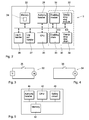
- FIG. 2 shows by means of a block diagram a robot control unit 3a according to an embodiment of the invention.
- the robot control unit includes communication means (not shown) for communicating with the TPU:s, a processor unit 20, such as a central processing unit (CPU) for executing software modules of the invention and stored robot programs, memory means 22, including a storage area 24 for storing an authority matrix, a login module 26 for handling login of the TPU:s to the control unit, a logout module 27 for handling logout of the TPU:s from the control unit, a TPU authority handler 28, which updates the authority matrix upon order of change of authority, and checks whether a move command is issue by a TPU having the authority therefore, and a safety system 30.
- a processor unit 20 such as a central processing unit (CPU) for executing software modules of the invention and stored robot programs
- memory means 22 including a storage area 24 for storing an authority matrix, a login module 26 for handling login of the TPU:s to the control unit, a logout module 27 for handling
- Each TPU has a unique identity, which, for example, is transferred to the control unit together with the desired authority upon login to the control unit.
- the authority matrix is a list including the identity of all TPU:s, which are connected to the control unit, and the authority of the TPU:s.
- the login handler 26 receives the identity and authority of the TPU during the login procedure and stores the identity and authority of the TPU in the authority matrix.
- the logout handler 27 removes the identity and authority of the TPU from the authority matrix upon receiving a logout order and disconnects the TPU from the safety system 30.
- the login handler 26 is also adapted to check whether the user is authorized to login to the control system or not based on stored information about authorization of the users.
- the authority handler 28 is also adapted to receive move commands from the TPU:s, wherein the move commands includes information about the identity of the TPU that issued the move command, to check whether the identity, included in the move command, is equal to the identity of the Master TPU, as stored in the authority matrix, and to allow the robot to move according to the move instruction, if the identity included in the move command is equal to the identity of the Master TPU, and to not allow the robot to move if the identity included in the move command is not equal to the identity of the Master TPU.
- a move command is for example a move command issued by the joystick 12, an order to start running a robot program including move instructions, or an order to stop running the robot program.
- the authority handler sends information to the CPU about whether or not the move command is allowed to be executed or not.
- the enabling signal ED enables manual movement of the manipulator if the received information indicates that the enabling devices for all TPU's connected to the safety system are simultaneously activated and does not enable manual movement of the manipulator if the information received indicates that at least one of the enabling devices connected to the safety system is deactivated. Information about the enabling signal ED is also communicated to the CPU. If the authority handler has allowed a move command, and the enabling signal enables manual movement, the CPU executes the move command; otherwise the move command is not executed.
- the enabling chain 33 comprises a switch 36 that is opened or closed in dependence on the enabling signal EC.
- the enabling chain 33 is connected to the motors M of the robot. When the enabling chain is broken, the brakes are applied to the motors and the robot no longer controls the motors.
- the enabling chain has to be activated before any user is allowed to operate the robot by the TPU.
- the enabling chain is for example activated when manual operation mode of the robot is selected. Activation of the enabling chain means that manual operation of the robot is enabled. Accordingly, when the enabling chain is activated, the enabling devices of the TPU:s connected to the safety system is operatable.
- the enabling chain 33 is opened or closed in dependence on whether the enabling signal ED enables manual movement of the robot or not. Accordingly, it is only possible to operate the robot by means of the Master TPU if the enabling devices for all TPU's connected to the safety system are simultaneously activate by the users.
- the login handler 26, the logout handler 27, the authority handler 28, the enabling check module 31, and the emergency stop check module 32 are software modules. Alternatively they can be implemented in hardware or a combination of software and hardware.
- FIGS. 6a-e are a flow diagrams illustrating a method and a computer program for coupling a wireless TPU to a robot controller, according to an embodiment of the present invention. It will be understood that each block of the flow diagram can be implemented by computer program instructions, which are executed by the central processing unit 20 of the control unit. A presumption is that a communication link has been established between the TPU:s and the control unit.
- the method according to the invention is event driven, which means that a certain sequence of method steps are executed based on a certain event.
- the events are for example: a login command is received from one of the TPU:s, a move command is received from one of the TPU:s, an emergency stop order is received from one of the TPU:s, an order to change authority is received from one of the TPU:s, and a logout command is received from one of the TPU:s.
- a login command is received from one of the TPU:s
- a move command is received from one of the TPU:s
- an emergency stop order is received from one of the TPU:s
- an order to change authority is received from one of the TPU:s
- a logout command is received from one of the TPU:s.
- FIG. 6a shows the login procedure.
- the TPU sends a login command to the control unit including a request to connect the TPU to the control unit, the identity of the operator, a password, the identity of the TPU, and the desired level of authority of the TPU.
- the control unit receives the login command, block 50, and checks if the operator is authorized to be logged in to the control unit, block 52. If the check reveals that the operator is authorized and the password is correct the operator is logged in to and connected to the control unit, block 54.
- the level of authority is a remote authority the login procedure is finished, otherwise the TPU is connected to the safety system, block 58, 60.
- the identity of the TPU is communicated to the safety system.
- the safety system enables the safety equipment of the TPU, which means that the enabling device and the emergency stop device of the TPU is functioning, block 62.
- the safety equipment of a TPU with a remote authority does not function, i.e. it is not possible to emergency stop the robot by activating the emergency stop button on the TPU, and it is not possible to enabling motion of the manipulator by activating the enabling button.
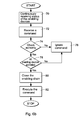
- Figure 6b shows a procedure for handling move commands from the TPU:s.
- the control unit continuously receives information about the status of the enabling devices from all TPU:s connected to the safety system, block 70.
- the status includes enabling device activated or deactivated.
- the control unit receives a command from any of the TPU:s, block 72, the control system is adapted to perform a check whether the TPU is allowed to issue this type of command or not according to its authority, block 74.
- Each command received from the TPU includes the identity of the TPU that issued the command.
- Information of the authority of the TPU, which issued the command is found in the authority matrix. If the check shows that the TPU does not have the authority to issue the command, the command is ignored and the TPU is informed thereof, block 76.
- Figure 6c shows a procedure for an emergency stop command from one of the TPU:s.
- the control unit continuously receives information about the status of the emergency stop devices from all TPU:s connected to the safety system, block 90.
- the status includes emergency stop activated or deactivated.
- the control system is adapted to detect whether the received status indicates that the emergency stop device of any of the TPU:s connected to the safety system is activated, block 92. If the control unit detects that one or more of the emergency stop device are activated, the emergency stop chain is closed and the robot is emergency stopped.
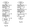
- Figure 6d shows a procedure for handling an order for changing the authority of two TPU:s.
- a TPU having a safety authority wants to change to the master authority, and the TPU having the master authority wants to change to the safety authority. It is also possible to order a change from a remote authority to a safety authority and vice versa.
- the control unit receives a request for changing the authority to master authority from a TPU having a safety level of authority, block 96.
- the control unit sends an inquiry to the Maser TPU about the change, block 98.
- the master TPU can choose to grant or deny the request.
- the control system receives the answer from the Master TPU, block 100. If the Master TPU grants the request, the new authorities are stored in the authority matrix. If the Master TPU denies the request, the authorities are not changed.
- the robot system is adapted to emergency stop the robot and log out all TPU:s from the control unit if an error occurs with a TPU connected to the safety system. Thereafter, all the TPU:s have to log in again to the control unit.
Landscapes
- Engineering & Computer Science (AREA)
- Robotics (AREA)
- Mechanical Engineering (AREA)
- Manipulator (AREA)
- Numerical Control (AREA)
- Switches With Compound Operations (AREA)
- Electrotherapy Devices (AREA)
Abstract
Description
- The present invention relates to an industrial robot system including an industrial robot comprising at least one manipulator and a control unit for controlling the manipulator, and at least two portable operator control devices, called TPU:s. The invention also relates to a method for controlling such a robot system.
- An industrial robot is programmed to carry out work along an operating path. In order to program or teach the robot the work, the robot is manipulated to positions along the desired operating path. These positions are stored as instructions in a memory in the control unit. During operation of the robot, the program instructions are executed, thereby making the robot operate as desired.
- The person controlling a robot is denoted an operator. In the following the words user and operator are used synonymously. An industrial robot can be operated in different operation modes. For example, when the robot is put in manual operation mode, the robot is controlled by means of a portable operator control device, generally denoted a Teach Pendant Unit, and called hereafter a TPU. The TPU is used for manually controlling the robot, for example to teach or program the robot to follow an operating path. The TPU may also be used for monitoring the robot program, changing certain variables in the program, starting, stopping and editing the program. When the robot is switched to automatic mode, it is no longer possible to manually move the robot with the joystick. However, it is still possible to start and stop the robot program.
- A TPU comprises operator control means, for example a joystick, a ball, a set of buttons or any combination thereof, a visual display unit, and safety equipment for protecting a user against injury during manual control of the robot, such as an enabling device and a stop device, for example an emergency stop button, or a conditional stop button. The enabling device is for example a switch or a push button, which has to be pressed by the operator to enable manual control of the robot by the TPU. For safety reasons the TPU normally is provided with either an emergency stop button, which makes it possible for the operator to unconditionally stop the robot at any time by pushing the button, or a conditional stop button, which makes it possible for the operator to conditionally stop the robot. The TPU is either wirelessly or physically connected to the control unit through a cable. If the TPU is wirelessly connected to the control unit, the TPU communicates with the control unit via a data link.
- During a login procedure the operator is logged in to the control unit of the robot and the TPU is connected to the control unit. Further, the TPU is connected to the safety system of the robot. To connect the TPU to the safety system of the robot includes activating the enabling function of the robot, which means to put the enabling device of the TPU into function. Thus, when the enabling function is activated, the enabling device of the TPU is enabled and it is possible to move the robot, for example by means of the joystick, when the enabling button of the TPU is pressed.
- To connect the TPU to the safety system of the robot also includes activating the emergency stop function of the robot, which for example means to put the emergency stop button of the TPU into function for the robot. When the emergency stop function of the TPU is activated, the emergency stop button of the TPU is enabled and it is possible to emergency stop the robot by pushing the emergency stop button. If the emergency stop function of the TPU is deactivated the emergency stop button of the TPU is disabled and nothing happens when the emergency stop button is pressed.
- When the operator no longer desires to control the robot, he has to disconnect the TPU from the control unit of the robot by sending a logout order from the TPU to the control unit. The logout order logs out the operator from the control unit and deactivates the safety system of the TPU, which means that the safety equipment of the TPU is disabled.
- For security reasons the manipulator is often placed into a robot cell. The robot cell is usually an enclosed area, for example a fence having a gate encloses the robot cell. The safety regulation for the robot specifies that the TPU must be connected to the safety system of the robot when the TPU is inside the robot cell, and to avoid accidents and unintended emergency stops of the robot, the safety equipment of the TPU should be out of function as long as the TPU is outside the robot cell.
- Sometimes it is necessary to be more than one user in the cell at the same time. If only one TPU is present in the robot cell, it is only the user with the TPU who has control over the robot and thus over what is happening in the cell. This could be very dangerous for the other users present in the cell. For example, if the user is testing a robot installation it can be very dangerous for the other users to be in the cell because of movements of the mechanical arms of the robot.
- The object of the present invention is to improve the safety in a robot cell when more than one person is present in the cell at the same time.
- According to one aspect of the invention this object is achieved with an industrial robot system as defined in
claim 1. - According to the invention the robot system comprises an industrial robot including at least one manipulator and a control unit for controlling the manipulator, and at least two TPU:s, which are adapted to be simultaneously connected to the safety system of the control unit and one of the TPU:s is a Master TPU, and the control unit is adapted to receive information from all TPU:s, which are simultaneously connected to the safety system, about whether the enabling device of the TPU is activated or deactivated, to permit manual movement of the robot by the Master TPU, if the received information indicates that the enabling devices for all TPU's connected to the safety system are simultaneously activated, to not permit manual movement of the Master TPU if the information received indicates that at least one of the enabling devices is deactivated, and to not permit manual movement of the robot by any other TPU than the Master TPU.
- The invention makes it possible for two or more TPU:s to be simultaneously connected to the safety system of the robot control unit. This means that all users in the robot cell could be provided with a TPU connected to the safety system. To increase the safety, only one user is the master and is allowed to move the robot. The other users are not allowed to move the robot, only to affect the safety system. To allow any movement of the robot, all users in the cell must simultaneously activate the enabling device, for example by pressing the enabling button. If one of the users releases the enabling button, i.e. deactivate the enabling device; the Master TPU is no longer allowed to move the manipulator. Accordingly, the safety for the other users in the cell is increased.
- The number of TPU:s simultaneously connected to the control unit may vary from time to time, in dependence on the number of users in the robot cell. Of course, the system also allows one TPU having master authority to be alone in the cell, and to control the movement of the manipulator, independent of any other TPU.
- Preferably, the control unit is adapted to receive information from one or more of the TPU:s about which of the simultaneously connected TPU:s has the master authority and accordingly is the Master TPU. Thus, it is possible for the users to decide which of the TPU:s is to be the Master TPU. For example, which of the TPU:s in the cell is to be Master TPU could be negotiated at login to the control unit. Alternatively, it is decided beforehand which TPU is the Master TPU and this information is previously stored in the control unit.
- According to an embodiment of the invention, the safety equipment comprises an emergency stop device and the control unit is adapted to receive information of from all TPU:s, which are simultaneously connected to the safety system, about whether the emergency stop device of the TPU is activated or deactivated, and to emergency stop the robot, if the received information indicates that the emergency stop device of at least one of the TPU's, connected to the safety system, is activated. This embodiment further increases the safety in a cell with more than one user, since it makes it possible to provide all the users with a TPU having an functioning emergency stop device, which works independently of the emergency stop devices of the other TPU:s. Thus, it is possible for all the users in the cell to emergency stop the robot.
- According to an embodiment of the invention, the control unit is adapted to upon order change authorities between the TPU:s, so that the Master TPU does no longer have a master authority and another of the TPU:s connected to the safety system instead becomes the Master TPU and have the master authority. In some situations it is a desire to switch the manual control of the robot to another user in the cell. This embodiment makes it possible to change authorities between the TPU:s so that another of the TPU:s in the cell instead becomes the Master TPU.
- According to an embodiment of the invention, the system allows TPU:s connected to the safety system to be assigned at least two different levels of authority, wherein the highest level of authority is a master authority. For example, the master authority allows the user to start and stop a robot program, and to move the robot by means of the joystick. For example, a second level of authority allows the user to view data, but not to control the robot. Due to the connection to the safety system, the safety equipment of the TPU is enabled and thereby the enabling device and the emergency stop device are in function.
- According to an embodiment of the invention, the system is adapted to allow a remote TPU to be connected to the control unit, but not to the safety system. The remote TPU is assigned a third level of authority. When a TPU is connected to the control unit, it is to be understood that a communication link is established between the TPU and the control unit. For example, the third level of authority may allow the user to communicate with the control unit and to view data from the control unit, but not to control the movements of robot, or to affect the safety system. This embodiment makes it possible to connect a TPU located outside the robot cell to the control unit and allows the user of the TPU to view data from the control unit. However, for safety reasons, the remote TPU is not allowed to affect the movements of the manipulator, to emergency stop the robot, or to enable or disable movement of the manipulator. It would be very dangerous if a TPU located outside the robot cell were allowed to control the movements of the manipulator if there are other users inside the robot cell.
- According to an embodiment of the invention, the control unit is adapted to check whether a move command, received from one of the TPU:s, is issued by the Master TPU, and to move the robot according to the move instruction if the move command is issued by the Master TPU, and to not move the robot if the move command is issued by a TPU which is not the Master TPU. In order to improve the safety, each received move command is checked to find out whether it was issued by the Master TPU or not. If a move command is not issued by the Master TPU, the command is not executed.
- According to an embodiment of the invention, the control unit comprises a storage area for storing the identity and authority of the TPU:s and the control unit is adapted to receive and store information about the identity and authority from each TPU connected to the control unit. Preferably, the control system is adapted to store the new authorities of the TPU:s in the storage area, upon the order to change the authorities between the TPU:s. Thus, the control unit will always have an updated authority matrix, which makes it easy keep track on which TPU:s are connected to the control unit at the moment and the authorities of the connected TPU:s.
- According to an embodiment of the invention, the control unit is adapted to receive move commands from the TPU:s, wherein each move command includes information about the identity of the TPU that issued the move command, to check whether the identity, included in the move command, is equal to the stored identity of the Master TPU, and to move the robot according to the move instruction if the identity included in the move command is equal to the identity of the Master TPU, and to not move the robot if the identity included in the move command is not equal to the identity of the Master TPU. Each move command issued by a TPU should contain the identity of the TPU, and the control unit checks whether a move command received from one of the TPU:s, is issued by the Master TPU, by comparing the identity contained in the received move command with the identity of the Master TPU stored in the authority matrix.
- The invention is applicable for TPU:s, which are physically connected to the control unit by means of cables as well as for wirelessly connected TPU:s. However, due to the risk for twisted cables, when more than one TPU is in the cell at the same time, it is to prefer to if the TPU:s are wirelessly connected to the control unit.
- According to one aspect of the invention this object is achieved with a method as defined in
claim 12. - According to a further aspect of the invention, the object is achieved by a computer program directly loadable into the internal memory of a computer or a processor, comprising software code portions for performing the steps of the method according to the appended set of method claims, when the program is run on a computer.
- According to another aspect of the invention, the object is achieved by a computer readable medium having a program recorded thereon, when the program is to make a computer perform the steps of the method according to the appended set of method claims, and the program is run on the computer.
- The invention will now be explained more closely by the description of different embodiments of the invention and with reference to the appended figures.
- Fig. 1
- shows an industrial robot system according to an embodiment of the invention.
- Fig. 2
- shows schematically a block diagram of a robot control unit according to an embodiment of the invention.
- Fig. 3
- shows an example of an enabling circuit.
- Fig. 4
- shows an example of an emergency stop circuit.
- Fig. 5
- shows schematically a block diagram of a TPU according to an embodiment of the invention.
- Figs. 6a-d
- show flow diagrams of a method for controlling an industrial robot system, according to an embodiment of the invention.
- Figure 1 shows an industrial robot system comprising an industrial robot located within a
robot cell 1 surrounded by a safety arrangement, for example a fence or a photo-electric trip device. A robot cell is a defined safe area surrounding the manipulator. Within the robot cell certain safety rules are applied. One safety rule is for example that the safety equipment of the TPU must function within the robot cell. The robot system includes amanipulator 2, acontrol unit 3 for controlling the manipulator, and a plurality of portableoperator control devices 5a-d, in the following denoted TPU:s (Teach Pendant Unit) for teaching and manually operating the manipulator. The TPU:s are communicating with thecontrol unit 3 via a wireless data link. It should be noted that in another embodiment of the invention, the TPU:s are connected to thecontrol unit 3 by means of cables. - Each
TPU 5a-d comprises aportable box 9 including adisplay screen 10, function keys, ajoystick 12, an enablingdevice 14 and anemergency stop device 15. The TPU also includes an antenna for wireless communication with thecontrol unit 3. The function keys permit the operator to select various states for the control system. Thejoystick 12 is used for controlling the movement of the manipulator when the robot is in manual operation mode. The enablingdevice 14 comprises a button, which has to be pressed down by the operator to enable control of the robot by the TPU. When the operator releases the button of the enablingdevice 14, the robot can no longer be operated by the TPU. Theemergency stop button 15 causes an emergency stop upon activation. The enablingdevice 14 and theemergency stop device 15 is a part of the safety equipment of the TPU. - In figure 1, there are four operators, each equipped with a
TPU 5a-d connected to thecontrol unit 3. It is to be understood that connected to the TPU means that the operator has been logged in to thecontrol unit 3 and is able to communicate with thecontrol unit 3 and to send and receive data from the control unit. Three of the TPU:s 5a-c are located inside the robot cell and oneTPU 5d is located outside the cell. - For safety reasons, the number of TPU:s allowed to be simultaneously connected to the control unit, or to the safety system, could be limited.
- In this embodiment of the invention, the robot system allows a TPU to be assigned three different levels of authorities: master authority, safety authority, and remote authority. The master authority is the highest level of authority and allows the TPU to be connected to the safety system of the control unit, i.e. allows enabling of the safety equipment of the TPU, and allows the operator to manually operate the robot, for example to move the manipulator with the joystick, and to start and stop robot programs. The safety authority is a lower level of authority, and allows the TPU to be connected to the safety system of the control unit, to communicate with the control unit and view data from the control unit, but not to manually operate the robot. The remote authority is the lowest level of authority, and allows the user to communicate with the control unit and view data from the control unit, but does not allow the operator to manually operate the robot, and it does not allow the TPU to be connected to the safety system of the control unit, which means that the safety equipment of the TPU does not function.
- According to the safety rules, a TPU located outside the robot cell must have the Remote authority, and a TPU located inside the robot cell must have either the Master authority or the Safety authority. However, only one of the TPU:s located inside the cell is allowed to have the Master authority, the other TPU:s inside the cell must have the safety authority. In this embodiment of the invention it is possible to change the authority so that another of the TPU:s connected to the safety system become the Master TPU. For example, the operator communicates a desired authority to the control system during a login procedure. Which one of the TPU:s is the master could be negotiated at the login procedure.
- The control unit is adapted to receive and store information about which of the simultaneously connected TPU:s has master authority and accordingly is Master TPU, to change the authority of the Master TPU to a lower level of authority, and to change the authority of another of the connected TPU: to the master authority. The TPU:s continuously send information about the status of the enabling devices, i.e. information about whether the enabling devices are activated or not, and information about the status of the emergency stop devices, i.e. information about whether the emergency stop devices are activated or not.
- Figure 2 shows by means of a block diagram a robot control unit 3a according to an embodiment of the invention. The robot control unit includes communication means (not shown) for communicating with the TPU:s, a
processor unit 20, such as a central processing unit (CPU) for executing software modules of the invention and stored robot programs, memory means 22, including astorage area 24 for storing an authority matrix, alogin module 26 for handling login of the TPU:s to the control unit, alogout module 27 for handling logout of the TPU:s from the control unit, aTPU authority handler 28, which updates the authority matrix upon order of change of authority, and checks whether a move command is issue by a TPU having the authority therefore, and asafety system 30. - Each TPU has a unique identity, which, for example, is transferred to the control unit together with the desired authority upon login to the control unit. The authority matrix is a list including the identity of all TPU:s, which are connected to the control unit, and the authority of the TPU:s. The
login handler 26 receives the identity and authority of the TPU during the login procedure and stores the identity and authority of the TPU in the authority matrix. Thelogout handler 27 removes the identity and authority of the TPU from the authority matrix upon receiving a logout order and disconnects the TPU from thesafety system 30. Thelogin handler 26 is also adapted to check whether the user is authorized to login to the control system or not based on stored information about authorization of the users. - The
authority handler 28 is adapted to, upon order from the TPU:s, change the authorities between two of the TPU:s, one of which is the Master TPU, so that the Master TPU does no longer have the master authority, and the other TPU instead becomes the Master TPU and accordingly has the master authority. The authority handler receives information from at least one of the two TPU:s about the change of authorities and the identity of the new Master TPU, and based thereon updates the authority matrix with the new authorities. In order to increase the safety, it is advantageous if one of the two TPU:s, which are changing authorities, sends an change order to the control unit and the other TPU sends a confirmation of the change to the control unit before the authorities are changed. - The
authority handler 28 is also adapted to receive move commands from the TPU:s, wherein the move commands includes information about the identity of the TPU that issued the move command, to check whether the identity, included in the move command, is equal to the identity of the Master TPU, as stored in the authority matrix, and to allow the robot to move according to the move instruction, if the identity included in the move command is equal to the identity of the Master TPU, and to not allow the robot to move if the identity included in the move command is not equal to the identity of the Master TPU. A move command is for example a move command issued by thejoystick 12, an order to start running a robot program including move instructions, or an order to stop running the robot program. The authority handler sends information to the CPU about whether or not the move command is allowed to be executed or not. - The
safety system 30 of the control unit includes an enablingmodule 31, anemergency stop module 32, an enablingchain 33, and anemergency stop chain 34. The enabling module and the emergency stop module holds information about which TPU:s are connected to the safety system. The enabling module continuously, or repeatedly within a certain time frame, receives information from all the TPU:s, which are simultaneously connected to said safety system, about whether the enabling devices of the TPU:s are activated or deactivated. The enabling module generates an enabling signal ED indicating whether manual movement of the robot is permitted or not. The enabling signal ED is transferred to the enablingchain 33. The enabling signal ED enables manual movement of the manipulator if the received information indicates that the enabling devices for all TPU's connected to the safety system are simultaneously activated and does not enable manual movement of the manipulator if the information received indicates that at least one of the enabling devices connected to the safety system is deactivated. Information about the enabling signal ED is also communicated to the CPU. If the authority handler has allowed a move command, and the enabling signal enables manual movement, the CPU executes the move command; otherwise the move command is not executed. - An example of the enabling
chain 33 is shown in figure 3. The enablingchain 33 comprises aswitch 36 that is opened or closed in dependence on the enabling signal EC. The enablingchain 33 is connected to the motors M of the robot. When the enabling chain is broken, the brakes are applied to the motors and the robot no longer controls the motors. The enabling chain has to be activated before any user is allowed to operate the robot by the TPU. The enabling chain is for example activated when manual operation mode of the robot is selected. Activation of the enabling chain means that manual operation of the robot is enabled. Accordingly, when the enabling chain is activated, the enabling devices of the TPU:s connected to the safety system is operatable. If the enabling circuit has been activated, the enablingchain 33 is opened or closed in dependence on whether the enabling signal ED enables manual movement of the robot or not. Accordingly, it is only possible to operate the robot by means of the Master TPU if the enabling devices for all TPU's connected to the safety system are simultaneously activate by the users. - The
emergency stop module 32 continuously receives information from all the TPU:s, which are simultaneously connected to the safety system, about whether the emergency stop devices of the TPU:s are activated or deactivated. The emergency stop module generates an emergency stop signal EV, indicating whether the robot should be emergency stopped or not. The emergency stop signal ES indicates that the robot shall be emergency stopped, if the emergency stop device of at least one of the TPU's, connected to the safety system, is activated, and indicates that the robot shall not be emergency stopped if non of the emergency stop device connected to the safety system is activated. The emergency stop signal ES is transferred to theemergency stop chain 34. An example of theemergency stop chain 34 is shown in figure 34. Theemergency stop chain 34 comprises aswitch 38 that is opened or closed in dependence on the emergency stop signal EV. Theemergency stop chain 34 is connected to the brakes B of the robot. Whenemergency stop chain 34 is broken, the brakes are applied to the motors. - In this embodiment of the invention, the
login handler 26, thelogout handler 27, theauthority handler 28, the enablingcheck module 31, and the emergencystop check module 32 are software modules. Alternatively they can be implemented in hardware or a combination of software and hardware. - Figure 5 shows by means of a block diagram a
TPU 5a-d according to an embodiment of the invention. The TPU includes communication means (not shown) for communicating with thecontrol unit 3, acentral processor unit 40, memory means 42, anauthority handler 44, and asafety circuit 46. The authority handier 44 handles authority issues, such as to communicate the desired authority to the control unit during the login procedure, to send an order about a change of the authority to the control unit, and to accept or deny a request regarding change of authority received from another TPU. Theauthority handler 44 also handles the communication with the operator regarding selection of level of authority and change of level of authority. The safety equipment includes asafety circuit 46 comprising theemergency stop button 15 and the enablingdevice 14, which both are switches. Thesafety circuit 46 is closed when the enablingdevice 14 is activated and thestop button 15 is not activated. - Figure 6a-e are a flow diagrams illustrating a method and a computer program for coupling a wireless TPU to a robot controller, according to an embodiment of the present invention. It will be understood that each block of the flow diagram can be implemented by computer program instructions, which are executed by the
central processing unit 20 of the control unit. A presumption is that a communication link has been established between the TPU:s and the control unit. The method according to the invention is event driven, which means that a certain sequence of method steps are executed based on a certain event. The events are for example: a login command is received from one of the TPU:s, a move command is received from one of the TPU:s, an emergency stop order is received from one of the TPU:s, an order to change authority is received from one of the TPU:s, and a logout command is received from one of the TPU:s. In the following it will be described, with reference to the flow diagrams 6a-e, what will happen in the control unit when those events occurs. - Figure 6a shows the login procedure. When the operator picks up the TPU and begins to use it, he enters information about his identity and a desired level of authority to the system. The TPU sends a login command to the control unit including a request to connect the TPU to the control unit, the identity of the operator, a password, the identity of the TPU, and the desired level of authority of the TPU. The control unit receives the login command, block 50, and checks if the operator is authorized to be logged in to the control unit, block 52. If the check reveals that the operator is authorized and the password is correct the operator is logged in to and connected to the control unit, block 54. If the desired authority is the master authority, the
authority handler 28 of the control unit checks whether any other TPU connected to the control unit already has been assigned the master authority. If so, the TPU is denied the master authority and is informed about that. If no other TPU has the master authority, or if a lower level of authority is claimed, the identity of the TPU and the level of authorization are stored in the authority matrix, block 56. - If the level of authority is a remote authority the login procedure is finished, otherwise the TPU is connected to the safety system, block 58, 60. Upon connection to the safety system, the identity of the TPU is communicated to the safety system. The safety system enables the safety equipment of the TPU, which means that the enabling device and the emergency stop device of the TPU is functioning, block 62. The safety equipment of a TPU with a remote authority does not function, i.e. it is not possible to emergency stop the robot by activating the emergency stop button on the TPU, and it is not possible to enabling motion of the manipulator by activating the enabling button.
- Figure 6b shows a procedure for handling move commands from the TPU:s. The control unit continuously receives information about the status of the enabling devices from all TPU:s connected to the safety system, block 70. The status includes enabling device activated or deactivated. When the control unit receives a command from any of the TPU:s, block 72, the control system is adapted to perform a check whether the TPU is allowed to issue this type of command or not according to its authority, block 74. Each command received from the TPU includes the identity of the TPU that issued the command. Information of the authority of the TPU, which issued the command, is found in the authority matrix. If the check shows that the TPU does not have the authority to issue the command, the command is ignored and the TPU is informed thereof, block 76.
- For example, if the control system receives a command involving a movement of the manipulator, or any other command, which is only allowed to be issued by the Master TPU, the command is ignored if the authority check shows the TPU does not have the master authority, block 76. If the enabling devices for all TPU:s connected to the safety system are activated, the enabling chain of the safety system is closed, block 78, 80, which means that it is possible to move the manipulator. If any of the enabling devices of the TPU:s connected to the safety system is deactivated, the enabling chain remains open and the move command is not executed. If the command involves a movement of the manipulator, if the command included the identity of the master TPU, and the enabling devices for all TPU:s connected to the safety system are activated, the move command is executed, block 82.
- Figure 6c shows a procedure for an emergency stop command from one of the TPU:s. The control unit continuously receives information about the status of the emergency stop devices from all TPU:s connected to the safety system, block 90. The status includes emergency stop activated or deactivated. The control system is adapted to detect whether the received status indicates that the emergency stop device of any of the TPU:s connected to the safety system is activated, block 92. If the control unit detects that one or more of the emergency stop device are activated, the emergency stop chain is closed and the robot is emergency stopped.
- Figure 6d shows a procedure for handling an order for changing the authority of two TPU:s. In this example, a TPU having a safety authority wants to change to the master authority, and the TPU having the master authority wants to change to the safety authority. It is also possible to order a change from a remote authority to a safety authority and vice versa. The control unit receives a request for changing the authority to master authority from a TPU having a safety level of authority, block 96. The control unit sends an inquiry to the Maser TPU about the change, block 98. The master TPU can choose to grant or deny the request. The control system receives the answer from the Master TPU, block 100. If the Master TPU grants the request, the new authorities are stored in the authority matrix. If the Master TPU denies the request, the authorities are not changed.
- Figure 6e shows a logout procedure. When the control system receives a logout command from the TPU, block 110, the control system removes the identity and authority of the TPU from the authority matrix, block 112. Further, the control system disconnects the TPU from the safety system and logs out the operator from the control system, block 114. The safety equipment of the TPU does no longer function and the operator can no longer view data from the control unit.
- According to an embodiment of the invention, the robot system is adapted to emergency stop the robot and log out all TPU:s from the control unit if an error occurs with a TPU connected to the safety system. Thereafter, all the TPU:s have to log in again to the control unit.
- The term comprises/comprising when used in this specification is taken to specify the presence of stated features, integers, steps or components. However, the term does not preclude the presence or addition of one or more additional features, integers, steps or components or groups thereof.
- The present invention is not limited to the embodiments disclosed but may be varied and modified within the scope of the following claims. For example the number of TPU:s may vary in dependence on the number of operators.
Claims (21)
- An industrial robot system comprising:an industrial robot including at least one manipulator (2) and a control unit (3) for controlling the manipulator, andat least two portable operator control devices (5a-d), called hereafter TPU:s, for manually operating the robot, each TPU comprising safety equipment including a manually operated enabling device (14), which upon activation enables manual movement of the robot by means of the TPU, and the control unit comprises a safety system (33,34) which upon connection enables the safety equipment of the TPU, characterized in that the system is adapted to simultaneously connect said TPU:s to the safety system of the control unit, wherein one of the TPU:s is given a master authority, called hereafter a Master TPU, and the control unit is adaptedto receive information from all TPU:s, which are simultaneously connected to said safety system, about whether the enabling device of the TPU is activated or deactivated,to permit manual movement of the robot by the Master TPU if said received information indicates that the enabling devices for all TPU's connected to the safety system are simultaneously activated,to not permit manual movement of the Master TPU if said information received indicates that at least one of the enabling devices is deactivated, andto not permit manual movement of the robot by any other TPU than the Master TPU.
- The industrial robot system according to claim 1, wherein said safety equipment comprises an emergency stop device (15) and the control unit is adapted
to receive information of from all TPU:s, which are simultaneously connected to said safety system, about whether the emergency stop device of the TPU is activated or deactivated, and
to emergency stop the robot, if said received information indicates that the emergency stop device of at least one of the TPU's, connected to the safety system, is activated. - The industrial robot system according to claim 1 or 2, wherein the control unit is adapted to upon order change authorities between the TPU:s, so that the Master TPU does no longer have a master authority and another of the TPU:s connected to the safety system instead becomes the Master TPU and have the master authority.
- The industrial robot system according to claim 3, wherein the control unit is adapted to receive information from at least one of the TPU:s about the change of authorities and the identity of the new Master TPU.
- The industrial robot system according to any of the previous claims, wherein the system allows TPU:s connected to the safety system to be assigned at least two different levels of authority, wherein the highest level of authority is master authority.
- The industrial robot system according claim 5, wherein the system is adapted to allow a remote TPU to be connected to the control unit, but not to the safety system, and to assign the remote TPU a third level of authority.
- The industrial robot system according to any of the previous claims, wherein the control unit is adapted
to check whether a move command, received from one of the TPU:s, is issued by the Master TPU, and
to move the robot according to the move instruction if the move command is issued by the Master TPU, and to not move the robot if the move command is issued by a TPU which is not the Master TPU. - The industrial robot system according to any of the previous claims, wherein the control unit comprises a storage area (24) for storing the identity and authority of the TPU:s, and the control unit is adapted to receive and store information about the identity and authority for each TPU connected to the control unit.
- The industrial robot system according to claim 3 and 8, wherein the control system is adapted to upon said order to change the authorities between the TPU:s store the new authorities of the TPU:s in said storage area.
- The industrial robot system according to claim 8 or 9, wherein the control unit is adapted
to receive move commands from the TPU:s, wherein the move commands include information about the identity of the TPU that issued the move command,
to check whether the identity, included in the move command, is equal to the stored identity of the Master TPU, and
to move the robot according to the move instruction if the identity included in the move command is equal to the identity of the Master TPU, and to not move the robot if the identity included in the move command is not equal to the identity of the Master TPU. - The industrial robot system according to any of the previous claims, wherein the TPU:s are adapted to communicate wirelessly with the control unit.
- A method for controlling an industrial robot system including an industrial robot comprising at least one manipulator and a control unit for controlling the manipulator, and at least two portable operator control devices, called hereafter TPU:s, for manually operating the robot, each TPU comprising safety equipment including a manually operated enabling device, which upon activation enables manual movement of the robot by means of the TPU, and the control unit comprises a safety system which upon connection enables the safety equipment of the TPU, characterized in that the method comprises:connecting the TPU:s to said safety system so that they are simultaneously connected to the safety system,receiving information about which of the connected TPU:s has master authority and accordingly is Master TPU,receiving information from all TPU:s, which are simultaneously connected to said safety system, about whether the enabling device of the TPU is activated or deactivated,receiving a move command from one of the connected TPU:s,deciding whether the move command is issued by the Master TPU or not,executing the move command if the move command is issued by the Master TPU and said received information indicates that the enabling devices for all TPU's connected to the safety system are simultaneously activated, otherwise not executing the move command.
- A method according to claim 12, wherein said safety equipment comprises an emergency stop device and the method further comprises:receiving information of from all TPU:s, which are simultaneously connected to said safety system, about whether the emergency stop device of the TPU is activated or deactivated, andexecuting an emergency stop of the robot, if said received information indicates that the emergency stop device of at least one of the TPU's connected to the safety system is activated.
- The method according to claim 13, wherein the method comprises receiving an order to change the authorities between the TPU:s, and based thereon changing the authorities so that the Master TPU does no longer have the master authority and another of the TPU:s connected to the safety system instead becomes the Master TPU and have the master authority.
- The method according to any of claims 12-14, wherein the method comprises receiving information about the identity and authority of the TPU:s connected to the control unit and saving the identity and authority of the connected TPU:s.
- The method according to claim 14 and 15, wherein said order to change the authorities comprises information of the identity of the new Master TPU, and the method comprises: changing the authority of the Master TPU to a lower level of authority, changing the authority of the new Master TPU to the master authority, and storing the new authorities.
- The method according to claim 16, wherein said move commands include information about the identity of the TPU that issued the move command, and the method comprises checking whether the identity, included in the move command, is equal to the stored identity of the Master TPU, and moving the robot according to the move instruction if the identity included in the move command is equal to the identity of the Master TPU, and to not move the robot if the identity included in the move command is not equal to the identity of the Master TPU.
- The method according to any of claims 12-17, wherein the TPU:s are assigned at least two different levels of authority, wherein the highest level of authority is the master authority.
- The method according to claim 18, wherein the TPU:s are assigned at least three different levels of authority, wherein the lowest level of authority is a remote authority, which allows the TPU to view data from the control unit, but not to be connected to the safety system.
- A computer program directly loadable into the internal memory of a computer, comprising software for performing the steps of any of claims 12-19.
- A computer readable medium, having a program recorded thereon, where the program is to make a computer perform the steps of any of claims 12-19, when said program is run on the computer.
Priority Applications (4)
| Application Number | Priority Date | Filing Date | Title |
|---|---|---|---|
| EP05110485A EP1782928B1 (en) | 2005-11-08 | 2005-11-08 | An industrial robot system with more than one TPU |
| AT05110485T ATE394206T1 (en) | 2005-11-08 | 2005-11-08 | INDUSTRIAL ROBOTIC SYSTEM WITH MORE THAN ONE HANDHELD DEVICE |
| DE602005006583T DE602005006583D1 (en) | 2005-11-08 | 2005-11-08 | Industrial robotic system with more than one handheld |
| PCT/EP2006/067793 WO2007054435A1 (en) | 2005-11-08 | 2006-10-26 | An industrial robot system with more than one tpu |
Applications Claiming Priority (1)
| Application Number | Priority Date | Filing Date | Title |
|---|---|---|---|
| EP05110485A EP1782928B1 (en) | 2005-11-08 | 2005-11-08 | An industrial robot system with more than one TPU |
Publications (2)
| Publication Number | Publication Date |
|---|---|
| EP1782928A1 true EP1782928A1 (en) | 2007-05-09 |
| EP1782928B1 EP1782928B1 (en) | 2008-05-07 |
Family
ID=36095790
Family Applications (1)
| Application Number | Title | Priority Date | Filing Date |
|---|---|---|---|
| EP05110485A Expired - Lifetime EP1782928B1 (en) | 2005-11-08 | 2005-11-08 | An industrial robot system with more than one TPU |
Country Status (3)
| Country | Link |
|---|---|
| EP (1) | EP1782928B1 (en) |
| AT (1) | ATE394206T1 (en) |
| DE (1) | DE602005006583D1 (en) |
Cited By (6)
| Publication number | Priority date | Publication date | Assignee | Title |
|---|---|---|---|---|
| WO2013029658A1 (en) * | 2011-08-30 | 2013-03-07 | Abb Technology Ag | Enabling device transferring robot control signals |
| JP2014184519A (en) * | 2013-03-25 | 2014-10-02 | Daihen Corp | Robot control system |
| JP2014193517A (en) * | 2013-02-27 | 2014-10-09 | Daihen Corp | Robot control device |
| JP2015044280A (en) * | 2013-07-29 | 2015-03-12 | 株式会社ダイヘン | Robot control device |
| DE102018219767A1 (en) * | 2018-11-19 | 2020-05-20 | Brendel Holding Gmbh & Co. Kg | EMERGENCY STOP SYSTEM FOR A PLANT |
| WO2021028709A1 (en) * | 2019-08-09 | 2021-02-18 | Nokia Technologies Oy | Apparatus and method for providing an emergency-stop switch for a network-controlled robot |
Families Citing this family (4)
| Publication number | Priority date | Publication date | Assignee | Title |
|---|---|---|---|---|
| JP7283205B2 (en) | 2019-04-25 | 2023-05-30 | 株式会社デンソーウェーブ | Robot system and operation authority setting program |
| JP7205972B2 (en) | 2019-05-24 | 2023-01-17 | 川崎重工業株式会社 | Teaching system |
| JP7813109B2 (en) * | 2021-08-31 | 2026-02-12 | 川崎重工業株式会社 | Robot System |
| JP7813108B2 (en) * | 2021-08-31 | 2026-02-12 | 川崎重工業株式会社 | Operation terminal, robot system and computer program |
Citations (4)
| Publication number | Priority date | Publication date | Assignee | Title |
|---|---|---|---|---|
| US20050052148A1 (en) * | 2001-10-23 | 2005-03-10 | Erik Carlson | Industrial robot system |
| EP1514650A1 (en) * | 2002-04-17 | 2005-03-16 | Kabushiki Kaisha Yaskawa Denki | Robot system and controller |
| JP2005118967A (en) * | 2003-10-20 | 2005-05-12 | Yaskawa Electric Corp | Robot system |
| WO2005065894A1 (en) * | 2004-01-08 | 2005-07-21 | Matsushita Electric Industrial Co., Ltd. | Industrial robot |
-
2005
- 2005-11-08 EP EP05110485A patent/EP1782928B1/en not_active Expired - Lifetime
- 2005-11-08 AT AT05110485T patent/ATE394206T1/en not_active IP Right Cessation
- 2005-11-08 DE DE602005006583T patent/DE602005006583D1/en not_active Expired - Lifetime
Patent Citations (5)
| Publication number | Priority date | Publication date | Assignee | Title |
|---|---|---|---|---|
| US20050052148A1 (en) * | 2001-10-23 | 2005-03-10 | Erik Carlson | Industrial robot system |
| EP1514650A1 (en) * | 2002-04-17 | 2005-03-16 | Kabushiki Kaisha Yaskawa Denki | Robot system and controller |
| JP2005118967A (en) * | 2003-10-20 | 2005-05-12 | Yaskawa Electric Corp | Robot system |
| WO2005065894A1 (en) * | 2004-01-08 | 2005-07-21 | Matsushita Electric Industrial Co., Ltd. | Industrial robot |
| EP1598152A1 (en) * | 2004-01-08 | 2005-11-23 | Matsushita Electric Industries Co., Ltd. | Industrial robot |
Non-Patent Citations (1)
| Title |
|---|
| PATENT ABSTRACTS OF JAPAN vol. 2003, no. 12 5 December 2003 (2003-12-05) * |
Cited By (7)
| Publication number | Priority date | Publication date | Assignee | Title |
|---|---|---|---|---|
| WO2013029658A1 (en) * | 2011-08-30 | 2013-03-07 | Abb Technology Ag | Enabling device transferring robot control signals |
| JP2014193517A (en) * | 2013-02-27 | 2014-10-09 | Daihen Corp | Robot control device |
| JP2014184519A (en) * | 2013-03-25 | 2014-10-02 | Daihen Corp | Robot control system |
| JP2015044280A (en) * | 2013-07-29 | 2015-03-12 | 株式会社ダイヘン | Robot control device |
| TWI679090B (en) * | 2013-07-29 | 2019-12-11 | 日商大亨股份有限公司 | Robot control apparatus |
| DE102018219767A1 (en) * | 2018-11-19 | 2020-05-20 | Brendel Holding Gmbh & Co. Kg | EMERGENCY STOP SYSTEM FOR A PLANT |
| WO2021028709A1 (en) * | 2019-08-09 | 2021-02-18 | Nokia Technologies Oy | Apparatus and method for providing an emergency-stop switch for a network-controlled robot |
Also Published As
| Publication number | Publication date |
|---|---|
| EP1782928B1 (en) | 2008-05-07 |
| DE602005006583D1 (en) | 2008-06-19 |
| ATE394206T1 (en) | 2008-05-15 |
Similar Documents
| Publication | Publication Date | Title |
|---|---|---|
| JP4773093B2 (en) | SAFETY CONTROL DEVICE AND METHOD OF LOADING NEW OPERATING PROGRAM ON SAFETY CONTROL DEVICE | |
| EP1782928B1 (en) | An industrial robot system with more than one TPU | |
| KR101290050B1 (en) | Device and method for secure control of a manipulator | |
| JP5502724B2 (en) | Control method of cargo transportation device | |
| CN110161987B (en) | Systems for protecting people from autonomously operating machines | |
| WO2006128784A2 (en) | An industrial robot system with a teaching portable unit and a detecting unit for detecting when the tpu leaves the robot cell | |
| CN101310234A (en) | Equipment monitoring and controlling device | |
| WO2009097895A1 (en) | An industrial robot system | |
| CN107250021B (en) | Method for operating an electronic security system with temporary participants | |
| JP7213274B2 (en) | machine tools with controls | |
| US20240165810A1 (en) | Method and system for automatically securing the operation of a robot system controlled by a mobile operating device | |
| WO2007054435A1 (en) | An industrial robot system with more than one tpu | |
| CN107879204A (en) | Elevator system with lockout mode | |
| CN200988223Y (en) | Device for controlling a robot by means of a wireless teaching pendant unit | |
| JP7669804B2 (en) | ROBOT CONTROL SYSTEM, INFORMATION PROCESSING APPARATUS, INFORMATION PROCESSING METHOD, AND PROGRAM | |
| US20050137746A1 (en) | System and method for communication between an industrial robot and a tpu | |
| JP4741940B2 (en) | Monitoring system and control device for mobile robot constituting the system | |
| CN113777967A (en) | Operating device for a safety locking device | |
| EP3687281B1 (en) | Control system, method and computer program for an automatic milking machine | |
| US20230386283A1 (en) | Safety Locking Device | |
| JP7575063B2 (en) | Autonomous driving work vehicle control system and vehicle control device | |
| JP6765489B2 (en) | Elevator operation check system and operation check method | |
| KR102209562B1 (en) | Disaster relief robot control system and cross over operation method | |
| JP7209188B2 (en) | Communication method, communication system, transmitter and receiver | |
| HK1080127A1 (en) | Method for controlling an automatic escape route door |
Legal Events
| Date | Code | Title | Description |
|---|---|---|---|
| PUAI | Public reference made under article 153(3) epc to a published international application that has entered the european phase |
Free format text: ORIGINAL CODE: 0009012 |
|
| 17P | Request for examination filed |
Effective date: 20061121 |
|
| AK | Designated contracting states |
Kind code of ref document: A1 Designated state(s): AT BE BG CH CY CZ DE DK EE ES FI FR GB GR HU IE IS IT LI LT LU LV MC NL PL PT RO SE SI SK TR |
|
| AX | Request for extension of the european patent |
Extension state: AL BA HR MK YU |
|
| R17P | Request for examination filed (corrected) |
Effective date: 20061121 |
|
| GRAP | Despatch of communication of intention to grant a patent |
Free format text: ORIGINAL CODE: EPIDOSNIGR1 |
|
| AKX | Designation fees paid |
Designated state(s): AT BE BG CH CY CZ DE DK EE ES FI FR GB GR HU IE IS IT LI LT LU LV MC NL PL PT RO SE SI SK TR |
|
| GRAS | Grant fee paid |
Free format text: ORIGINAL CODE: EPIDOSNIGR3 |
|
| GRAA | (expected) grant |
Free format text: ORIGINAL CODE: 0009210 |
|
| AK | Designated contracting states |
Kind code of ref document: B1 Designated state(s): AT BE BG CH CY CZ DE DK EE ES FI FR GB GR HU IE IS IT LI LT LU LV MC NL PL PT RO SE SI SK TR |
|
| REG | Reference to a national code |
Ref country code: GB Ref legal event code: FG4D |
|
| REG | Reference to a national code |
Ref country code: CH Ref legal event code: EP |
|
| REG | Reference to a national code |
Ref country code: IE Ref legal event code: FG4D Free format text: LANGUAGE OF EP DOCUMENT: FRENCH |
|
| REF | Corresponds to: |
Ref document number: 602005006583 Country of ref document: DE Date of ref document: 20080619 Kind code of ref document: P |
|
| PG25 | Lapsed in a contracting state [announced via postgrant information from national office to epo] |
Ref country code: SI Free format text: LAPSE BECAUSE OF FAILURE TO SUBMIT A TRANSLATION OF THE DESCRIPTION OR TO PAY THE FEE WITHIN THE PRESCRIBED TIME-LIMIT Effective date: 20080507 |
|
| PG25 | Lapsed in a contracting state [announced via postgrant information from national office to epo] |
Ref country code: ES Free format text: LAPSE BECAUSE OF FAILURE TO SUBMIT A TRANSLATION OF THE DESCRIPTION OR TO PAY THE FEE WITHIN THE PRESCRIBED TIME-LIMIT Effective date: 20080818 Ref country code: FI Free format text: LAPSE BECAUSE OF FAILURE TO SUBMIT A TRANSLATION OF THE DESCRIPTION OR TO PAY THE FEE WITHIN THE PRESCRIBED TIME-LIMIT Effective date: 20080507 Ref country code: NL Free format text: LAPSE BECAUSE OF FAILURE TO SUBMIT A TRANSLATION OF THE DESCRIPTION OR TO PAY THE FEE WITHIN THE PRESCRIBED TIME-LIMIT Effective date: 20080507 |
|
| NLV1 | Nl: lapsed or annulled due to failure to fulfill the requirements of art. 29p and 29m of the patents act | ||
| PG25 | Lapsed in a contracting state [announced via postgrant information from national office to epo] |
Ref country code: LV Free format text: LAPSE BECAUSE OF FAILURE TO SUBMIT A TRANSLATION OF THE DESCRIPTION OR TO PAY THE FEE WITHIN THE PRESCRIBED TIME-LIMIT Effective date: 20080507 Ref country code: PL Free format text: LAPSE BECAUSE OF FAILURE TO SUBMIT A TRANSLATION OF THE DESCRIPTION OR TO PAY THE FEE WITHIN THE PRESCRIBED TIME-LIMIT Effective date: 20080507 Ref country code: AT Free format text: LAPSE BECAUSE OF FAILURE TO SUBMIT A TRANSLATION OF THE DESCRIPTION OR TO PAY THE FEE WITHIN THE PRESCRIBED TIME-LIMIT Effective date: 20080507 |
|
| PG25 | Lapsed in a contracting state [announced via postgrant information from national office to epo] |
Ref country code: IS Free format text: LAPSE BECAUSE OF FAILURE TO SUBMIT A TRANSLATION OF THE DESCRIPTION OR TO PAY THE FEE WITHIN THE PRESCRIBED TIME-LIMIT Effective date: 20080907 |
|
| PG25 | Lapsed in a contracting state [announced via postgrant information from national office to epo] |
Ref country code: DK Free format text: LAPSE BECAUSE OF FAILURE TO SUBMIT A TRANSLATION OF THE DESCRIPTION OR TO PAY THE FEE WITHIN THE PRESCRIBED TIME-LIMIT Effective date: 20080507 Ref country code: LT Free format text: LAPSE BECAUSE OF FAILURE TO SUBMIT A TRANSLATION OF THE DESCRIPTION OR TO PAY THE FEE WITHIN THE PRESCRIBED TIME-LIMIT Effective date: 20080507 Ref country code: SE Free format text: LAPSE BECAUSE OF FAILURE TO SUBMIT A TRANSLATION OF THE DESCRIPTION OR TO PAY THE FEE WITHIN THE PRESCRIBED TIME-LIMIT Effective date: 20080807 Ref country code: CZ Free format text: LAPSE BECAUSE OF FAILURE TO SUBMIT A TRANSLATION OF THE DESCRIPTION OR TO PAY THE FEE WITHIN THE PRESCRIBED TIME-LIMIT Effective date: 20080507 |
|
| PG25 | Lapsed in a contracting state [announced via postgrant information from national office to epo] |
Ref country code: RO Free format text: LAPSE BECAUSE OF FAILURE TO SUBMIT A TRANSLATION OF THE DESCRIPTION OR TO PAY THE FEE WITHIN THE PRESCRIBED TIME-LIMIT Effective date: 20080507 Ref country code: SK Free format text: LAPSE BECAUSE OF FAILURE TO SUBMIT A TRANSLATION OF THE DESCRIPTION OR TO PAY THE FEE WITHIN THE PRESCRIBED TIME-LIMIT Effective date: 20080507 Ref country code: PT Free format text: LAPSE BECAUSE OF FAILURE TO SUBMIT A TRANSLATION OF THE DESCRIPTION OR TO PAY THE FEE WITHIN THE PRESCRIBED TIME-LIMIT Effective date: 20081007 Ref country code: BE Free format text: LAPSE BECAUSE OF FAILURE TO SUBMIT A TRANSLATION OF THE DESCRIPTION OR TO PAY THE FEE WITHIN THE PRESCRIBED TIME-LIMIT Effective date: 20080507 |
|
| PLBE | No opposition filed within time limit |
Free format text: ORIGINAL CODE: 0009261 |
|
| STAA | Information on the status of an ep patent application or granted ep patent |
Free format text: STATUS: NO OPPOSITION FILED WITHIN TIME LIMIT |
|
| 26N | No opposition filed |
Effective date: 20090210 |
|
| PG25 | Lapsed in a contracting state [announced via postgrant information from national office to epo] |
Ref country code: EE Free format text: LAPSE BECAUSE OF FAILURE TO SUBMIT A TRANSLATION OF THE DESCRIPTION OR TO PAY THE FEE WITHIN THE PRESCRIBED TIME-LIMIT Effective date: 20080507 Ref country code: BG Free format text: LAPSE BECAUSE OF FAILURE TO SUBMIT A TRANSLATION OF THE DESCRIPTION OR TO PAY THE FEE WITHIN THE PRESCRIBED TIME-LIMIT Effective date: 20080807 |
|
| PG25 | Lapsed in a contracting state [announced via postgrant information from national office to epo] |
Ref country code: MC Free format text: LAPSE BECAUSE OF NON-PAYMENT OF DUE FEES Effective date: 20081130 |
|
| PG25 | Lapsed in a contracting state [announced via postgrant information from national office to epo] |
Ref country code: IE Free format text: LAPSE BECAUSE OF NON-PAYMENT OF DUE FEES Effective date: 20081108 |
|
| REG | Reference to a national code |
Ref country code: CH Ref legal event code: PL |
|
| GBPC | Gb: european patent ceased through non-payment of renewal fee |
Effective date: 20091108 |
|
| PG25 | Lapsed in a contracting state [announced via postgrant information from national office to epo] |
Ref country code: CY Free format text: LAPSE BECAUSE OF FAILURE TO SUBMIT A TRANSLATION OF THE DESCRIPTION OR TO PAY THE FEE WITHIN THE PRESCRIBED TIME-LIMIT Effective date: 20080507 Ref country code: HU Free format text: LAPSE BECAUSE OF FAILURE TO SUBMIT A TRANSLATION OF THE DESCRIPTION OR TO PAY THE FEE WITHIN THE PRESCRIBED TIME-LIMIT Effective date: 20081108 Ref country code: LU Free format text: LAPSE BECAUSE OF NON-PAYMENT OF DUE FEES Effective date: 20081108 |
|
| PG25 | Lapsed in a contracting state [announced via postgrant information from national office to epo] |
Ref country code: TR Free format text: LAPSE BECAUSE OF FAILURE TO SUBMIT A TRANSLATION OF THE DESCRIPTION OR TO PAY THE FEE WITHIN THE PRESCRIBED TIME-LIMIT Effective date: 20080507 |
|
| PG25 | Lapsed in a contracting state [announced via postgrant information from national office to epo] |
Ref country code: LI Free format text: LAPSE BECAUSE OF NON-PAYMENT OF DUE FEES Effective date: 20091130 Ref country code: CH Free format text: LAPSE BECAUSE OF NON-PAYMENT OF DUE FEES Effective date: 20091130 Ref country code: GR Free format text: LAPSE BECAUSE OF FAILURE TO SUBMIT A TRANSLATION OF THE DESCRIPTION OR TO PAY THE FEE WITHIN THE PRESCRIBED TIME-LIMIT Effective date: 20080808 |
|
| PG25 | Lapsed in a contracting state [announced via postgrant information from national office to epo] |
Ref country code: GB Free format text: LAPSE BECAUSE OF NON-PAYMENT OF DUE FEES Effective date: 20091108 |
|
| REG | Reference to a national code |
Ref country code: FR Ref legal event code: PLFP Year of fee payment: 11 |
|
| PGFP | Annual fee paid to national office [announced via postgrant information from national office to epo] |
Ref country code: DE Payment date: 20151119 Year of fee payment: 11 Ref country code: IT Payment date: 20151125 Year of fee payment: 11 |
|
| PGFP | Annual fee paid to national office [announced via postgrant information from national office to epo] |
Ref country code: FR Payment date: 20151119 Year of fee payment: 11 |
|
| REG | Reference to a national code |
Ref country code: DE Ref legal event code: R119 Ref document number: 602005006583 Country of ref document: DE |
|
| REG | Reference to a national code |
Ref country code: FR Ref legal event code: ST Effective date: 20170731 |
|
| PG25 | Lapsed in a contracting state [announced via postgrant information from national office to epo] |
Ref country code: FR Free format text: LAPSE BECAUSE OF NON-PAYMENT OF DUE FEES Effective date: 20161130 Ref country code: IT Free format text: LAPSE BECAUSE OF NON-PAYMENT OF DUE FEES Effective date: 20161108 |
|
| PG25 | Lapsed in a contracting state [announced via postgrant information from national office to epo] |
Ref country code: DE Free format text: LAPSE BECAUSE OF NON-PAYMENT OF DUE FEES Effective date: 20170601 |