EP1781068A1 - System and method for an adaptor for interconnecting a hearing assistance device to a sound conduit - Google Patents
System and method for an adaptor for interconnecting a hearing assistance device to a sound conduit Download PDFInfo
- Publication number
- EP1781068A1 EP1781068A1 EP06255531A EP06255531A EP1781068A1 EP 1781068 A1 EP1781068 A1 EP 1781068A1 EP 06255531 A EP06255531 A EP 06255531A EP 06255531 A EP06255531 A EP 06255531A EP 1781068 A1 EP1781068 A1 EP 1781068A1
- Authority
- EP
- European Patent Office
- Prior art keywords
- adaptor
- spout
- hearing assistance
- assistance device
- sound conduit
- Prior art date
- Legal status (The legal status is an assumption and is not a legal conclusion. Google has not performed a legal analysis and makes no representation as to the accuracy of the status listed.)
- Withdrawn
Links
Images

Classifications
-
- H—ELECTRICITY
- H04—ELECTRIC COMMUNICATION TECHNIQUE
- H04R—LOUDSPEAKERS, MICROPHONES, GRAMOPHONE PICK-UPS OR LIKE ACOUSTIC ELECTROMECHANICAL TRANSDUCERS; ELECTRIC HEARING AIDS; PUBLIC ADDRESS SYSTEMS
- H04R25/00—Electric hearing aids
- H04R25/65—Housing parts, e.g. shells, tips or moulds, or their manufacture
- H04R25/652—Ear tips; Ear moulds
- H04R25/656—Non-customized, universal ear tips, i.e. ear tips which are not specifically adapted to the size or shape of the ear or ear canal
-
- H—ELECTRICITY
- H04—ELECTRIC COMMUNICATION TECHNIQUE
- H04R—LOUDSPEAKERS, MICROPHONES, GRAMOPHONE PICK-UPS OR LIKE ACOUSTIC ELECTROMECHANICAL TRANSDUCERS; ELECTRIC HEARING AIDS; PUBLIC ADDRESS SYSTEMS
- H04R25/00—Electric hearing aids
- H04R25/60—Mounting or interconnection of hearing aid parts, e.g. inside tips, housings or to ossicles
-
- H—ELECTRICITY
- H04—ELECTRIC COMMUNICATION TECHNIQUE
- H04R—LOUDSPEAKERS, MICROPHONES, GRAMOPHONE PICK-UPS OR LIKE ACOUSTIC ELECTROMECHANICAL TRANSDUCERS; ELECTRIC HEARING AIDS; PUBLIC ADDRESS SYSTEMS
- H04R2225/00—Details of deaf aids covered by H04R25/00, not provided for in any of its subgroups
- H04R2225/021—Behind the ear [BTE] hearing aids
- H04R2225/0213—Constructional details of earhooks, e.g. shape, material
-
- H—ELECTRICITY
- H04—ELECTRIC COMMUNICATION TECHNIQUE
- H04R—LOUDSPEAKERS, MICROPHONES, GRAMOPHONE PICK-UPS OR LIKE ACOUSTIC ELECTROMECHANICAL TRANSDUCERS; ELECTRIC HEARING AIDS; PUBLIC ADDRESS SYSTEMS
- H04R25/00—Electric hearing aids
- H04R25/60—Mounting or interconnection of hearing aid parts, e.g. inside tips, housings or to ossicles
- H04R25/607—Mounting or interconnection of hearing aid parts, e.g. inside tips, housings or to ossicles of earhooks
-
- H—ELECTRICITY
- H04—ELECTRIC COMMUNICATION TECHNIQUE
- H04R—LOUDSPEAKERS, MICROPHONES, GRAMOPHONE PICK-UPS OR LIKE ACOUSTIC ELECTROMECHANICAL TRANSDUCERS; ELECTRIC HEARING AIDS; PUBLIC ADDRESS SYSTEMS
- H04R25/00—Electric hearing aids
- H04R25/65—Housing parts, e.g. shells, tips or moulds, or their manufacture
Definitions
- This disclosure relates generally to hearing assistance devices, and more particularly to a system and method for an adaptor for interconnecting hearing assistance devices to sound conduit.
- Hearing assistance devices are available to help users hear.
- Some hearing assistance device designs include a threaded spout. This spout extends from the hearing assistance device housing and allows for the connection of some hearing assistance device parts. But some parts are unable to efficiently connect to this spout.
- An incompatible fit between a part and the spout can introduce an air gap. An air gap can cause feedback problems and can decrease performance.
- An inability to connect parts to the sound conduit causes additional problems.
- One problem is that users are not able to retrofit parts to the spout if the parts cannot form an acoustic seal with the spout. This can force hearing assistance device users to completely replace their hearing assistance device system. Additionally, users may seek to mix parts made by different manufactures. This is not possible if parts are incompatible and cannot form an acoustic seal. As such, what is needed is a way to connect incompatible parts to a threaded spout so that an acoustic seal exists between the incompatible part and the hearing assistance device.
- the present invention provides an apparatus to connect an acoustic sound conduit to a threaded spout of a hearing assistance device, comprising:
- One embodiment of the present subject matter includes an apparatus for connecting a threaded spout of a hearing assistance device to an acoustic sound conduit, the apparatus having a first portion having an adaptor passageway adapted to mate to the spout; and a second portion adapted to provide a interference fit with the acoustic sound conduit; wherein the apparatus is adapted to connect the hearing assistance device and the acoustic sound conduit such that the hearing assistance device, the apparatus, and acoustic sound conduit define an acoustically sealed passageway extending from within the hearing assistance device and through the acoustic sound conduit.
- the adaptor passageway is linear. In additional embodiments it is at least partially threaded. In some embodiments it is cylindrical.
- the adaptor is sealed to a spout using threads.
- a seal is created by connecting the adaptor and the spout with a seal disposed therebetween. Seals within the present scope include o-ring and washer types.
- the present subject matter in various embodiments, includes a nipple at which a sound conduit is connected.
- the nipple may continuously stretch the sound conduit.
- the nipple defines part of the adaptor passageway, in various embodiments.
- An additional embodiment of the present subject matter includes an apparatus for connection to a threaded spout of a hearing assistance device, the apparatus having an adaptor having a first portion with an adaptor passageway adapted to mate to the threaded spout, and a second portion interference fitted to an acoustic sound conduit, wherein the apparatus is adapted to connect the hearing assistance device such that the hearing assistance device, the adaptor, and acoustic sound conduit define an acoustically sealed passageway extending from within the hearing assistance device and through the acoustic sound conduit.
- an embodiment of the present subject matter includes an apparatus for an ear, the apparatus having a hearing assistance device housing shaped to fit at least partially behind the ear, the hearing assistance device housing containing a microphone, sound processing electronics, and a speaker to deliver sound to a spout at an aperture in the hearing assistance device housing; an adaptor having an adaptor passage acoustically sealed to the aperture in the hearing assistance device housing; and a sound conduit defining a lumen which is acoustically sealed, at a proximal portion, to the adaptor passage of the adaptor.
- the present subject matter is directed toward hearing assistance devices.
- Many hearing assistance devices include a spout.
- the spout is threaded, and includes a passageway adapted to transmit acoustic sound.
- Some users seek to attach parts to the spout which are not compatible with the spout. For instance, some incompatible parts lack threads to match the threads of a spout.
- Such an assembly often demonstrates air gaps between the incompatible part and the spout. Air gaps can cause feedback and can decrease performance.
- the present subject matter provides an adaptor which provides for the connection of otherwise incompatible parts to the threaded spout.
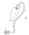
- FIG. 1 shows a perspective view of an assembly including a hearing assistance device housing, a spout, an adaptor, a sound conduit, and an earpiece, according to one embodiment of the present subject matter.
- the present illustration shows one embodiment of a hearing assistance device housing 102.
- the hearing assistance device housing 102 is shaped to fit at least partially behind an ear. This configuration is known in the art as a behind-the-ear (“BTE") configuration. Optional configurations within the scope of the present subject matter extend beyond embodiments using BTE housings.
- BTE behind-the-ear
- the pictured configuration shows an adaptor 106 connected to a spout 104.
- the spout is a separate piece which is acoustically sealed to the hearing assistance device housing 102.
- the spout 104 is integrated with the housing.
- the spout in various embodiments, includes a passageway. As such, in embodiments in which the spout 104 is integrated with the housing 102, the spout 104 at least partially defines an aperture in the hearing assistance device housing 102.
- the present subject matter includes spout embodiments in which the spout provides for an acoustically sealed sound passageway for sound emanating from within the hearing assistance device housing 102.
- the spout is a hollow, cylindrical boss having threads. These threads are suited for attachment of a device, such as a plastic ear hook, in various embodiments. Such a spout configuration, however, does not provide for a sealable connection to some parts. For instance, some sound conduits are not compatible with the threads of the spout. As such, embodiments within the present scope provide an adaptor 106 adapted to form an acoustically sealed connection to the spout 104. Adaptor 106, in various embodiments, is suited for mating with a sound conduit 110 such that an acoustic seal exists between the hearing assistance device housing 102, the spout 104, the adaptor 106, and the sound conduit 110.
- a sound tube is used.
- the sound conduit 110 is continuous and defines an acoustically sealed lumen. Some embodiments are not continuous and include multiple subcomponents. Some embodiments include a sound conduit 110 which is rubber or which has rubber subcomponents. Additional embodiments within the present subject matter include other materials.
- a sound conduit 110 defines a lumen used to transmit sound in an acoustically sealed manner.
- the sound conduit is acoustically sealed to the adaptor 106 at a proximal end, and is acoustically sealed to an earpiece 112 at a distal end.
- the earpiece 112 is shaped to at least partially fit an ear canal of the ear. Additional embodiments do not include an earpiece. Some of these embodiments terminate in a distal aperture which is shaped for positioning nearby an ear canal.
- the sound conduit is sized to fit the ear.
- These embodiments include designs in which the sound conduit 110 provides support for the hearing assistance device housing 102 and the earpiece 112.
- the sound conduit has rigidity such that it fastens the distal portion of the sound conduit near the ear canal, and further fastens the hearing assistance device housing at least partially behind the ear.
- the sound conduit 110 extends over the ear.
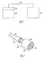
- FIG. 2 is a schematic showing an adaptor, a hearing assistance device housing and a sound port, according to one embodiment of the present subject matter.
- Various embodiments include an adaptor 208 connected to a sound conduit 204.
- the sound conduit 204 is connected to a sound port 206.
- the sound port 206 is an aperture in the sound conduit 204.
- the sound port 206 is defined within an earpiece.
- the interconnected hearing assistance device 202, adaptor 208, sound conduit 204 and sound port 206 define an acoustically sealed passageway extending from within the hearing assistance device 202 to the sound port 206, in various embodiments.
- sound conduit 204 and sound port 206 are assembled from part of a kit.
- kits in various embodiments, additionally include adaptor 208.
- these kits provide a user with the ability to adapt a non-threaded sound conduit to a threaded hearing assistance device spout.
- kit embodiments additionally provide the user with several options for earpiece use. Users having such tools are able to adapt a preferred sound conduit, which is incompatible with a threaded spout, to the threaded spout.
- a hearing assistance device having a spout with an ear hook connected to the spout is disassembled such that the spout is exposed.
- Adaptor 208 is attached to the spout such that a sound tube is used in place of the hook.
- kits are useful in a variety of applications besides kit embodiments. Such applications include use with new hearing assistance devices, use as new assemblies for attachment to housings, use as retrofit kits, and other uses.
- FIG. 3 shows a perspective view of an adaptor attached to a sound conduit, according to one embodiment of the present subject matter.
- the present subject matter includes multiple adaptor designs.
- the adaptor 306 is plastic.
- adaptor 306 is metal.
- Some embodiments of adaptor 306 include machined steel.
- Some embodiments of adaptor 306 include brass.
- the pictured adaptor 306 is represented in two portions: a first portion 310 and a second portion 312.
- an acoustically sealed adaptor passageway extends continuously through both of these portions.
- threads 308 extend along the adaptor passageway at least partially through the first portion 310.
- these threads 308 are mateable to threads of a spout.
- the threads 308 of the adaptor 306 form an acoustic seal with the threads of the spout.
- the adaptor 306 includes a non-threaded portion of the adaptor passageway which forms an acoustically sealed connection with the spout.
- the spout threads are self starting and are engaged with the adaptor passageway defining a mating seal with the spout.
- various embodiments include a nipple through which the adaptor passageway extends.
- the nipple includes a barb 304 which is adapted for mating with a sound conduit 302.
- Other designs for the second portion 312 which are adapted to attach to a sound conduit additionally fall within the present scope. Lips, ridges, and other attachment designs work within the present scope.
- male tubes sized for mating with a female aperture in the sound conduit also fall within the present scope.
- the sound conduit 302 is stretched over a friction fit portion of the second portion 312. In some embodiments, a sound conduit is stretched over a barb 304 of a nipple of the second portion 312. In some additional embodiments, the sound conduit 302 is only momentarily stretched during installation, and exhibits minimal elastic stretch in use.
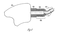
- FIG. 4 shows a side view of a hearing assistance device housing and a side view partial cross section of an adaptor and a spout, according to one embodiment of the present subject matter.
- Various embodiments include a hearing assistance device housing 402, a spout 404, and an adaptor 406.
- the embodiment illustrated demonstrates spout threads mated to adaptor threads.
- the illustrated embodiment shows an adaptor variation in which a first portion 408 of the adaptor 406 and a second portion 410 of the adaptor include a bend.
- a generally tubular, acoustically sealed passage is angled at an angle A1.
- Angle A1 is selectable based on design needs. Some designs are straight, and other designs are angled to suit user comfort.
- the present subject matter includes a seal disposed between the adaptor 406 and the spout 404.
- some embodiments include one or more o-rings disposed between the adaptor 406 and the spout 404. O-rings made from rubber fall within the present scope of embodiments. Additional materials are also possible.
- some embodiments include a washer. Some of these embodiments include a washer having a low durometer rubber. Other sealing methods, including films, adhesives, and other sealing technologies additionally fall within the present scope.
- FIG. 5 shows a side view of an adaptor, according to one embodiment of the present subject matter.
- the embodiment includes an adaptor having a first portion 502 and a second portion 510.
- the second portion includes a barb 506.
- the first portion 502 is mateable to a hearing assistance device.
- the second portion 510 is mateable to a sound conduit.
- the adaptor is generally tubular and the second portion 510 has a smaller diameter than the first portion 502. Additionally pictured are threads 504.
- the material of the adaptor 502 defines an adaptor passageway 508. The following table includes dimensions for the embodiment.
- the dimensions listed in table 1 are approximate.
- the present subject matter includes dimensions having respective tolerances.
- the linear dimensions D1-D13 each have a tolerance of+/- 0.001 inches.
- the angular dimension according to some manufacturing embodiments, has a tolerance of +/- 0.5 degrees. It should be noted that these dimensions are directed toward one embodiment, and other embodiments within the scope of the present subject matter include other dimensions which vary from the dimensions of Table 1.
- FIG. 6 shows a side view of a spout, according to one embodiment of the present subject matter. Pictured are threads 602 of the spout. Additionally pictured is a spout base 604. Some embodiments include a spout base, and some embodiments include threads which extend to the hearing assistance device. The present subject matter includes embodiments in which the spout base extends away from the hearing assistance device at different lengths. In some embodiments, spout base 604 includes a surface texture. Other embodiments are smooth. The material of the spout defines a spout passageway 606.
- FIG. 7 shows an assembly including a spout and an adaptor, according to one embodiment of the present subject matter. Pictured are the adaptor 702 and the spout 704. The threads of the adaptor 702 and the spout 704 are shown interlocked. In such an embodiment, the present subject matter provides for an acoustic seal along a passageway including adaptor passageway 706 and spout passageway 708.
Landscapes
- Engineering & Computer Science (AREA)
- Health & Medical Sciences (AREA)
- General Health & Medical Sciences (AREA)
- Neurosurgery (AREA)
- Otolaryngology (AREA)
- Physics & Mathematics (AREA)
- Acoustics & Sound (AREA)
- Signal Processing (AREA)
- Manufacturing & Machinery (AREA)
- Measurement Of The Respiration, Hearing Ability, Form, And Blood Characteristics Of Living Organisms (AREA)
Abstract
Description
- This disclosure relates generally to hearing assistance devices, and more particularly to a system and method for an adaptor for interconnecting hearing assistance devices to sound conduit.
- Hearing assistance devices are available to help users hear. Some hearing assistance device designs include a threaded spout. This spout extends from the hearing assistance device housing and allows for the connection of some hearing assistance device parts. But some parts are unable to efficiently connect to this spout. An incompatible fit between a part and the spout can introduce an air gap. An air gap can cause feedback problems and can decrease performance.
- An inability to connect parts to the sound conduit causes additional problems. One problem is that users are not able to retrofit parts to the spout if the parts cannot form an acoustic seal with the spout. This can force hearing assistance device users to completely replace their hearing assistance device system. Additionally, users may seek to mix parts made by different manufactures. This is not possible if parts are incompatible and cannot form an acoustic seal. As such, what is needed is a way to connect incompatible parts to a threaded spout so that an acoustic seal exists between the incompatible part and the hearing assistance device.
- The above-mentioned problems and others not expressly discussed herein are addressed by the present subject matter and will be understood by reading and studying this specification.
- The present invention provides an apparatus to connect an acoustic sound conduit to a threaded spout of a hearing assistance device, comprising:
- an adaptor including a threaded portion to mate with the threaded spout and a second portion adapted to provide an interference fit with the acoustic sound conduit.
- One embodiment of the present subject matter includes an apparatus for connecting a threaded spout of a hearing assistance device to an acoustic sound conduit, the apparatus having a first portion having an adaptor passageway adapted to mate to the spout; and a second portion adapted to provide a interference fit with the acoustic sound conduit; wherein the apparatus is adapted to connect the hearing assistance device and the acoustic sound conduit such that the hearing assistance device, the apparatus, and acoustic sound conduit define an acoustically sealed passageway extending from within the hearing assistance device and through the acoustic sound conduit.
- The present subject matter includes several variations. In some embodiments, the adaptor passageway is linear. In additional embodiments it is at least partially threaded. In some embodiments it is cylindrical.
- In some embodiments, the adaptor is sealed to a spout using threads. In other embodiments, a seal is created by connecting the adaptor and the spout with a seal disposed therebetween. Seals within the present scope include o-ring and washer types.
- The present subject matter, in various embodiments, includes a nipple at which a sound conduit is connected. The nipple may continuously stretch the sound conduit. The nipple defines part of the adaptor passageway, in various embodiments.
- An additional embodiment of the present subject matter includes an apparatus for connection to a threaded spout of a hearing assistance device, the apparatus having an adaptor having a first portion with an adaptor passageway adapted to mate to the threaded spout, and a second portion interference fitted to an acoustic sound conduit, wherein the apparatus is adapted to connect the hearing assistance device such that the hearing assistance device, the adaptor, and acoustic sound conduit define an acoustically sealed passageway extending from within the hearing assistance device and through the acoustic sound conduit.
- Additionally, an embodiment of the present subject matter includes an apparatus for an ear, the apparatus having a hearing assistance device housing shaped to fit at least partially behind the ear, the hearing assistance device housing containing a microphone, sound processing electronics, and a speaker to deliver sound to a spout at an aperture in the hearing assistance device housing; an adaptor having an adaptor passage acoustically sealed to the aperture in the hearing assistance device housing; and a sound conduit defining a lumen which is acoustically sealed, at a proximal portion, to the adaptor passage of the adaptor.
- This Summary is an overview of some of the teachings of the present application and not intended to be an exclusive or exhaustive treatment of the present subject matter. Further details about the present subject matter are found in the detailed description and appended claims. Other aspects will be apparent to persons skilled in the art upon reading and understanding the following detailed description and viewing the drawings that form a part thereof, each of which are not to be taken in a limiting sense. The scope of the present invention is defined by the appended claims and their legal equivalents.
- A preferred embodiment of the present invention will now be described by way of example only with reference to the accompanying drawings, in which:
- FIG. 1 shows a perspective view of an assembly including a hearing assistance device housing, a spout, an adaptor, a sound conduit, and an earpiece, according to one embodiment of the present subject matter;
- FIG. 2 is a schematic showing an adaptor, a hearing assistance device housing and a sound port, according to one embodiment of the present subject matter;
- FIG. 3 shows a perspective view of an adaptor attached to a sound conduit, according to one embodiment of the present subject matter;
- FIG. 4 shows a side view of a hearing assistance device housing and a side view partial cross section of an adaptor and a spout, according to one embodiment of the present subject matter;
- FIG. 5 shows a side view of an adaptor, according to one embodiment of the present subject matter;
- FIG. 6 shows a side view of a spout, according to one embodiment of the present subject matter; and
- FIG. 7 shows an assembly including a spout and an adaptor, according to one embodiment of the present subject
- The present subject matter is directed toward hearing assistance devices. Many hearing assistance devices include a spout. Often, the spout is threaded, and includes a passageway adapted to transmit acoustic sound. Some users seek to attach parts to the spout which are not compatible with the spout. For instance, some incompatible parts lack threads to match the threads of a spout. Such an assembly often demonstrates air gaps between the incompatible part and the spout. Air gaps can cause feedback and can decrease performance. In various embodiments, the present subject matter provides an adaptor which provides for the connection of otherwise incompatible parts to the threaded spout.
- FIG. 1 shows a perspective view of an assembly including a hearing assistance device housing, a spout, an adaptor, a sound conduit, and an earpiece, according to one embodiment of the present subject matter. The present illustration shows one embodiment of a hearing
assistance device housing 102. In various embodiments, the hearingassistance device housing 102 is shaped to fit at least partially behind an ear. This configuration is known in the art as a behind-the-ear ("BTE") configuration. Optional configurations within the scope of the present subject matter extend beyond embodiments using BTE housings. - The pictured configuration shows an
adaptor 106 connected to aspout 104. In some embodiments, the spout is a separate piece which is acoustically sealed to the hearingassistance device housing 102. In some hearing assistance device designs, thespout 104 is integrated with the housing. The spout, in various embodiments, includes a passageway. As such, in embodiments in which thespout 104 is integrated with thehousing 102, thespout 104 at least partially defines an aperture in the hearingassistance device housing 102. Overall, the present subject matter includes spout embodiments in which the spout provides for an acoustically sealed sound passageway for sound emanating from within the hearingassistance device housing 102. - In various embodiments, the spout is a hollow, cylindrical boss having threads. These threads are suited for attachment of a device, such as a plastic ear hook, in various embodiments. Such a spout configuration, however, does not provide for a sealable connection to some parts. For instance, some sound conduits are not compatible with the threads of the spout. As such, embodiments within the present scope provide an
adaptor 106 adapted to form an acoustically sealed connection to thespout 104.Adaptor 106, in various embodiments, is suited for mating with asound conduit 110 such that an acoustic seal exists between the hearingassistance device housing 102, thespout 104, theadaptor 106, and thesound conduit 110. - Various forms of
sound conduit 110 are used in the present subject matter. In some embodiments, a sound tube is used. In some embodiments, thesound conduit 110 is continuous and defines an acoustically sealed lumen. Some embodiments are not continuous and include multiple subcomponents. Some embodiments include asound conduit 110 which is rubber or which has rubber subcomponents. Additional embodiments within the present subject matter include other materials. In various embodiments, asound conduit 110 defines a lumen used to transmit sound in an acoustically sealed manner. - In various embodiments, the sound conduit is acoustically sealed to the
adaptor 106 at a proximal end, and is acoustically sealed to anearpiece 112 at a distal end. In various embodiments, theearpiece 112 is shaped to at least partially fit an ear canal of the ear. Additional embodiments do not include an earpiece. Some of these embodiments terminate in a distal aperture which is shaped for positioning nearby an ear canal. - In some embodiments, the sound conduit is sized to fit the ear. These embodiments include designs in which the
sound conduit 110 provides support for the hearingassistance device housing 102 and theearpiece 112. In some of these embodiments, the sound conduit has rigidity such that it fastens the distal portion of the sound conduit near the ear canal, and further fastens the hearing assistance device housing at least partially behind the ear. In some embodiments, thesound conduit 110 extends over the ear. - FIG. 2 is a schematic showing an adaptor, a hearing assistance device housing and a sound port, according to one embodiment of the present subject matter. Various embodiments include an
adaptor 208 connected to asound conduit 204. In various embodiments, thesound conduit 204 is connected to asound port 206. In various embodiments, thesound port 206 is an aperture in thesound conduit 204. In additional embodiments, thesound port 206 is defined within an earpiece. Overall, the interconnectedhearing assistance device 202,adaptor 208,sound conduit 204 andsound port 206 define an acoustically sealed passageway extending from within thehearing assistance device 202 to thesound port 206, in various embodiments. - In some embodiments,
sound conduit 204 andsound port 206 are assembled from part of a kit. Such kits, in various embodiments, additionally includeadaptor 208. In some embodiments, these kits provide a user with the ability to adapt a non-threaded sound conduit to a threaded hearing assistance device spout. These kit embodiments additionally provide the user with several options for earpiece use. Users having such tools are able to adapt a preferred sound conduit, which is incompatible with a threaded spout, to the threaded spout. - In some embodiments, a hearing assistance device having a spout with an ear hook connected to the spout is disassembled such that the spout is exposed.
Adaptor 208 is attached to the spout such that a sound tube is used in place of the hook. - One should note that the present subject matter is useful in a variety of applications besides kit embodiments. Such applications include use with new hearing assistance devices, use as new assemblies for attachment to housings, use as retrofit kits, and other uses.
- FIG. 3 shows a perspective view of an adaptor attached to a sound conduit, according to one embodiment of the present subject matter. The present subject matter includes multiple adaptor designs. In some embodiments, the
adaptor 306 is plastic. In additional embodiments,adaptor 306 is metal. Some embodiments ofadaptor 306 include machined steel. Some embodiments ofadaptor 306 include brass. - For explanation, the pictured
adaptor 306 is represented in two portions: afirst portion 310 and asecond portion 312. In some of these embodiments, an acoustically sealed adaptor passageway extends continuously through both of these portions. In some embodiments,threads 308 extend along the adaptor passageway at least partially through thefirst portion 310. In various embodiments, thesethreads 308 are mateable to threads of a spout. In some assembled embodiments, thethreads 308 of theadaptor 306 form an acoustic seal with the threads of the spout. - In some embodiments, the
adaptor 306 includes a non-threaded portion of the adaptor passageway which forms an acoustically sealed connection with the spout. As such, in some assembled embodiments, the spout threads are self starting and are engaged with the adaptor passageway defining a mating seal with the spout. - Regarding the
second portion 312, various embodiments include a nipple through which the adaptor passageway extends. In some embodiments, the nipple includes abarb 304 which is adapted for mating with asound conduit 302. Other designs for thesecond portion 312 which are adapted to attach to a sound conduit additionally fall within the present scope. Lips, ridges, and other attachment designs work within the present scope. Additionally, male tubes sized for mating with a female aperture in the sound conduit also fall within the present scope. - In various embodiments, the
sound conduit 302 is stretched over a friction fit portion of thesecond portion 312. In some embodiments, a sound conduit is stretched over abarb 304 of a nipple of thesecond portion 312. In some additional embodiments, thesound conduit 302 is only momentarily stretched during installation, and exhibits minimal elastic stretch in use. - FIG. 4 shows a side view of a hearing assistance device housing and a side view partial cross section of an adaptor and a spout, according to one embodiment of the present subject matter. Various embodiments include a hearing
assistance device housing 402, aspout 404, and anadaptor 406. The embodiment illustrated demonstrates spout threads mated to adaptor threads. - The illustrated embodiment shows an adaptor variation in which a
first portion 408 of theadaptor 406 and asecond portion 410 of the adaptor include a bend. In one embodiment, a generally tubular, acoustically sealed passage is angled at an angle A1. Angle A1 is selectable based on design needs. Some designs are straight, and other designs are angled to suit user comfort. - In various embodiments, the present subject matter includes a seal disposed between the
adaptor 406 and thespout 404. For instance, some embodiments include one or more o-rings disposed between theadaptor 406 and thespout 404. O-rings made from rubber fall within the present scope of embodiments. Additional materials are also possible. Further, some embodiments include a washer. Some of these embodiments include a washer having a low durometer rubber. Other sealing methods, including films, adhesives, and other sealing technologies additionally fall within the present scope. - FIG. 5 shows a side view of an adaptor, according to one embodiment of the present subject matter. The embodiment includes an adaptor having a
first portion 502 and asecond portion 510. In various embodiments, the second portion includes abarb 506. In various embodiments, thefirst portion 502 is mateable to a hearing assistance device. In some embodiments, thesecond portion 510 is mateable to a sound conduit. In various embodiments, the adaptor is generally tubular and thesecond portion 510 has a smaller diameter than thefirst portion 502. Additionally pictured arethreads 504. The material of theadaptor 502 defines anadaptor passageway 508. The following table includes dimensions for the embodiment.Table 1: Dimensions Dimension Name Value D 1 0.300 inches D2 0.229 inches D3 0.191 inches D4 0.179 inches D5 0.159 inches D6 0.129 inches D7 0.140 inches D8 0.070 inches D9 0.058 inches D10 0.040 inches D11 0.049 inches D12 0.069 inches D13 98.1 degrees - The dimensions listed in table 1 are approximate. The present subject matter includes dimensions having respective tolerances. For instance, in one embodiment, the linear dimensions D1-D13 each have a tolerance of+/- 0.001 inches. The angular dimension, according to some manufacturing embodiments, has a tolerance of +/- 0.5 degrees. It should be noted that these dimensions are directed toward one embodiment, and other embodiments within the scope of the present subject matter include other dimensions which vary from the dimensions of Table 1.
- FIG. 6 shows a side view of a spout, according to one embodiment of the present subject matter. Pictured are
threads 602 of the spout. Additionally pictured is aspout base 604. Some embodiments include a spout base, and some embodiments include threads which extend to the hearing assistance device. The present subject matter includes embodiments in which the spout base extends away from the hearing assistance device at different lengths. In some embodiments,spout base 604 includes a surface texture. Other embodiments are smooth. The material of the spout defines aspout passageway 606. - FIG. 7 shows an assembly including a spout and an adaptor, according to one embodiment of the present subject matter. Pictured are the
adaptor 702 and thespout 704. The threads of theadaptor 702 and thespout 704 are shown interlocked. In such an embodiment, the present subject matter provides for an acoustic seal along a passageway includingadaptor passageway 706 andspout passageway 708. - Although specific embodiments have been illustrated and described herein, it will be appreciated by those of ordinary skill in the art that any arrangement which is calculated to achieve the same purpose may be substituted for the specific embodiment shown. This application is intended to cover adaptations or variations of the present subject matter. It is to be understood that the above description is intended to be illustrative, and not restrictive. Combinations of the above embodiments, and other embodiments will be apparent to those of skill in the art upon reviewing the above description. The scope of the present subject matter should be determined with reference to the appended claims, along with the full scope of equivalents to which such claims are entitled.
Claims (13)
- An apparatus to connect an acoustic sound conduit to a threaded spout of a hearing assistance device, comprising:an adaptor including a threaded portion to mate with the threaded spout and a second portion adapted to provide an interference fit with the acoustic sound conduit.
- The apparatus of claim 1, wherein a second portion is adapted to provide an interference fit with the acoustic sound conduit such that the adaptor provides an acoustically sealed passage between the hearing assistance device housing and the acoustic sound conduit, the acoustically sealed passage adapted to communicate sound with the hearing assistance device.
- The apparatus of any of the preceding claims, wherein a first portion includes a first sound passageway which is approximately linear, and the second portion includes a second sound passageway is approximately linear, and the first sound passageway is in linear alignment with the second sound passageway.
- The apparatus of any of the preceding claims, wherein the second portion is generally tubular.
- The apparatus of any of the preceding claims, wherein the second portion includes a nipple.
- The apparatus of claim 1, further comprising the first portion mated to the hearing assistance device, and the second portion mated to the sound conduit, wherein the second portion has a smaller diameter than the first portion.
- The apparatus of any of the preceding claims, wherein the acoustic sound conduit is stretched over the nipple.
- The apparatus of any of the preceding claims, further comprising a deformed material mated to the threads of the threaded spout and defining an acoustic seal.
- The apparatus of any of the preceding claims, wherein a seal is disposed between the threaded end and the threaded spout.
- The apparatus of any of the preceding claims, wherein an earpiece is acoustically sealed to the acoustic sound conduit.
- The apparatus of any of the preceding claims, wherein the sound conduit is shaped to fit an ear.
- The apparatus of any of the preceding claims, including a o-ring seal disposed between the threaded end and the threaded spout.
- The apparatus of any of claims 1-11, including a washer disposed between the threaded end and the threaded spout.
Applications Claiming Priority (1)
| Application Number | Priority Date | Filing Date | Title |
|---|---|---|---|
| US11/258,842 US20070092094A1 (en) | 2005-10-26 | 2005-10-26 | System and method for an adaptor for interconnecting a hearing assistance device to a sound conduit |
Publications (1)
| Publication Number | Publication Date |
|---|---|
| EP1781068A1 true EP1781068A1 (en) | 2007-05-02 |
Family
ID=37600835
Family Applications (1)
| Application Number | Title | Priority Date | Filing Date |
|---|---|---|---|
| EP06255531A Withdrawn EP1781068A1 (en) | 2005-10-26 | 2006-10-26 | System and method for an adaptor for interconnecting a hearing assistance device to a sound conduit |
Country Status (3)
| Country | Link |
|---|---|
| US (1) | US20070092094A1 (en) |
| EP (1) | EP1781068A1 (en) |
| CA (1) | CA2564753A1 (en) |
Cited By (2)
| Publication number | Priority date | Publication date | Assignee | Title |
|---|---|---|---|---|
| US10425714B2 (en) | 2016-10-19 | 2019-09-24 | Sonion Nederland B.V. | Ear bud or dome |
| EP3672284A3 (en) * | 2018-12-17 | 2020-08-05 | Kind Hörgeräte GmbH & Co. Kg | Otoplastic and use of an otoplastic |
Families Citing this family (13)
| Publication number | Priority date | Publication date | Assignee | Title |
|---|---|---|---|---|
| US7899200B2 (en) * | 2006-06-02 | 2011-03-01 | Phonak Ag | Universal-fit hearing device |
| DE102006046698B4 (en) * | 2006-10-02 | 2011-06-16 | Siemens Audiologische Technik Gmbh | Sound conductor and hearing device |
| DE102007014131A1 (en) * | 2007-03-23 | 2008-09-25 | Siemens Audiologische Technik Gmbh | Hearing aid with a fastening of a receiver tube |
| DE102007055550A1 (en) * | 2007-11-21 | 2009-05-28 | Siemens Medical Instruments Pte. Ltd. | Carrying hook for attachment to a hearing aid and hearing aid |
| US20090232342A1 (en) * | 2008-03-14 | 2009-09-17 | Hearing Components, Inc. | Earbud adapter with increased flexibility region |
| EP2107831A3 (en) * | 2008-03-31 | 2010-12-29 | Starkey Laboratories, Inc. | Real ear measurement adaptor with internal sound conduit |
| USD634848S1 (en) * | 2010-01-08 | 2011-03-22 | Sonic Innovations, Inc. | Hearing aid |
| USD693007S1 (en) * | 2012-07-03 | 2013-11-05 | Aria Innovations, Inc | Open ear hearing aid |
| USD794612S1 (en) * | 2016-03-04 | 2017-08-15 | Chris J. Katopis | Earbud |
| USD789910S1 (en) * | 2016-03-13 | 2017-06-20 | Chris J. Katopis | Earbud |
| USD808365S1 (en) * | 2016-03-25 | 2018-01-23 | Chris J. Katopis | Earbud |
| USD813845S1 (en) * | 2016-03-31 | 2018-03-27 | Chris J. Katopis | Earbud |
| USD941986S1 (en) * | 2019-07-12 | 2022-01-25 | Make Great Sales Limited | Earplug |
Citations (3)
| Publication number | Priority date | Publication date | Assignee | Title |
|---|---|---|---|---|
| GB2039191A (en) * | 1978-12-15 | 1980-07-30 | Danavox As | Hookshaped part of a behind-the ear hearing aid |
| DE20007574U1 (en) * | 2000-04-26 | 2000-07-06 | Siemens Audiologische Technik Gmbh, 91058 Erlangen | Hearing aid portable with an adapter behind the ear |
| DE20108827U1 (en) * | 2001-05-26 | 2001-09-27 | Borowsky, Hans-Dieter, 48485 Neuenkirchen | Tubular body for sound transmission |
Family Cites Families (12)
| Publication number | Priority date | Publication date | Assignee | Title |
|---|---|---|---|---|
| US2938083A (en) * | 1957-12-30 | 1960-05-24 | Sonotone Corp | Transistor amplifier hearing aid unit with receiver vibration feedback suppression |
| US2991333A (en) * | 1960-09-02 | 1961-07-04 | Maico Electronics Inc | Acoustical device |
| US3101155A (en) * | 1961-03-14 | 1963-08-20 | Dictograph Products Inc | Compact housing |
| US4381830A (en) * | 1981-07-27 | 1983-05-03 | Jelonek Chester J | Continuous flow earmold tubing connector |
| US4977976A (en) * | 1988-09-27 | 1990-12-18 | Microsonic, Inc. | Connector for hearing air earmold |
| US5975235A (en) * | 1995-10-23 | 1999-11-02 | Schlaegel; Norman D. | Seating member for connecting a continuous-flow earmold tubing connector to an earmold |
| EP0997057B1 (en) * | 1997-07-18 | 2006-12-13 | Resound Corporation | Behind the ear hearing aid system |
| US6009183A (en) * | 1998-06-30 | 1999-12-28 | Resound Corporation | Ambidextrous sound delivery tube system |
| US6681022B1 (en) * | 1998-07-22 | 2004-01-20 | Gn Resound North Amerca Corporation | Two-way communication earpiece |
| US6748094B1 (en) * | 2000-03-03 | 2004-06-08 | Advanced Bionics Corporation | Connector system for BTE hearing devices |
| US6775389B2 (en) * | 2001-08-10 | 2004-08-10 | Advanced Bionics Corporation | Ear auxiliary microphone for behind the ear hearing prosthetic |
| US7142926B2 (en) * | 2002-08-30 | 2006-11-28 | Advanced Bionics Corporation | Quick connect earhook system for BTE devices |
-
2005
- 2005-10-26 US US11/258,842 patent/US20070092094A1/en not_active Abandoned
-
2006
- 2006-10-20 CA CA002564753A patent/CA2564753A1/en not_active Abandoned
- 2006-10-26 EP EP06255531A patent/EP1781068A1/en not_active Withdrawn
Patent Citations (3)
| Publication number | Priority date | Publication date | Assignee | Title |
|---|---|---|---|---|
| GB2039191A (en) * | 1978-12-15 | 1980-07-30 | Danavox As | Hookshaped part of a behind-the ear hearing aid |
| DE20007574U1 (en) * | 2000-04-26 | 2000-07-06 | Siemens Audiologische Technik Gmbh, 91058 Erlangen | Hearing aid portable with an adapter behind the ear |
| DE20108827U1 (en) * | 2001-05-26 | 2001-09-27 | Borowsky, Hans-Dieter, 48485 Neuenkirchen | Tubular body for sound transmission |
Cited By (2)
| Publication number | Priority date | Publication date | Assignee | Title |
|---|---|---|---|---|
| US10425714B2 (en) | 2016-10-19 | 2019-09-24 | Sonion Nederland B.V. | Ear bud or dome |
| EP3672284A3 (en) * | 2018-12-17 | 2020-08-05 | Kind Hörgeräte GmbH & Co. Kg | Otoplastic and use of an otoplastic |
Also Published As
| Publication number | Publication date |
|---|---|
| US20070092094A1 (en) | 2007-04-26 |
| CA2564753A1 (en) | 2007-04-26 |
Similar Documents
| Publication | Publication Date | Title |
|---|---|---|
| US20070092094A1 (en) | System and method for an adaptor for interconnecting a hearing assistance device to a sound conduit | |
| US11076245B2 (en) | Ball and socket connection with an acoustic seal and mounting interface for a hearing assistance device | |
| CN102158790B (en) | Hearing aid with removable attached earpiece | |
| US9025807B2 (en) | Couplable hearing apparatus for a hearing device, coupling element and hearing device | |
| JP5385301B2 (en) | Modular hearing aid | |
| US8867768B2 (en) | Earpiece assembly with foil clip | |
| US8861762B2 (en) | Hearing aid and an ear piece for a hearing aid | |
| CN103517195B (en) | Hybrid sound equipment utensil system connector | |
| JP6144865B2 (en) | Hearing assistance device having a wall formed of a printed circuit board | |
| EP1626612A3 (en) | Hearing aid microphone mounting structure and method for mounting | |
| CN103634729B (en) | Sound equipment utensil and the ear piece of band receiver | |
| US8130993B2 (en) | Hearing device with a securing system for a receiver tube | |
| US9258657B2 (en) | Method of manufacturing a soft custom ear mold and a soft custom ear mold | |
| EP1583395A3 (en) | All-in-the-ear hearing-aid for binaural treatment of a patient | |
| DE102007023054A1 (en) | Earmold with adapter seal | |
| EP2284956A3 (en) | Nut seal assemly for coaxial connector | |
| EP1341397A3 (en) | Split shell for hearing aids | |
| CN219516187U (en) | Handle shell, handle and endoscope | |
| EP1715237A3 (en) | Pipe fitting with composite gasket assembly | |
| US9118995B1 (en) | Earpiece auditory devices having improved ear tips | |
| US20060188122A1 (en) | Swivel elbow | |
| EP1416766A3 (en) | Hearing aid battery door seal | |
| CN219049753U (en) | Electric breast pump joint | |
| EP0968895A3 (en) | Pressure transducer adapter | |
| US20260107099A1 (en) | In-ear device with a cerumen protection unit |
Legal Events
| Date | Code | Title | Description |
|---|---|---|---|
| PUAI | Public reference made under article 153(3) epc to a published international application that has entered the european phase |
Free format text: ORIGINAL CODE: 0009012 |
|
| AK | Designated contracting states |
Kind code of ref document: A1 Designated state(s): AT BE BG CH CY CZ DE DK EE ES FI FR GB GR HU IE IS IT LI LT LU LV MC NL PL PT RO SE SI SK TR |
|
| AX | Request for extension of the european patent |
Extension state: AL BA HR MK YU |
|
| 17P | Request for examination filed |
Effective date: 20071004 |
|
| 17Q | First examination report despatched |
Effective date: 20071106 |
|
| AKX | Designation fees paid |
Designated state(s): AT BE BG CH CY CZ DE DK EE ES FI FR GB GR HU IE IS IT LI LT LU LV MC NL PL PT RO SE SI SK TR |
|
| STAA | Information on the status of an ep patent application or granted ep patent |
Free format text: STATUS: THE APPLICATION IS DEEMED TO BE WITHDRAWN |
|
| 18D | Application deemed to be withdrawn |
Effective date: 20080517 |