EP1780942A1 - Method for automatically discovering a bus system in a multipoint transport network, multipoint transport network and network node - Google Patents
Method for automatically discovering a bus system in a multipoint transport network, multipoint transport network and network node Download PDFInfo
- Publication number
- EP1780942A1 EP1780942A1 EP05292255A EP05292255A EP1780942A1 EP 1780942 A1 EP1780942 A1 EP 1780942A1 EP 05292255 A EP05292255 A EP 05292255A EP 05292255 A EP05292255 A EP 05292255A EP 1780942 A1 EP1780942 A1 EP 1780942A1
- Authority
- EP
- European Patent Office
- Prior art keywords
- nodes
- node
- conditions
- information
- bus
- Prior art date
- Legal status (The legal status is an assumption and is not a legal conclusion. Google has not performed a legal analysis and makes no representation as to the accuracy of the status listed.)
- Withdrawn
Links
Images

Classifications
-
- H—ELECTRICITY
- H04—ELECTRIC COMMUNICATION TECHNIQUE
- H04L—TRANSMISSION OF DIGITAL INFORMATION, e.g. TELEGRAPHIC COMMUNICATION
- H04L12/00—Data switching networks
- H04L12/28—Data switching networks characterised by path configuration, e.g. LAN [Local Area Networks] or WAN [Wide Area Networks]
- H04L12/40—Bus networks
- H04L12/40169—Flexible bus arrangements
-
- H—ELECTRICITY
- H04—ELECTRIC COMMUNICATION TECHNIQUE
- H04L—TRANSMISSION OF DIGITAL INFORMATION, e.g. TELEGRAPHIC COMMUNICATION
- H04L41/00—Arrangements for maintenance, administration or management of data switching networks, e.g. of packet switching networks
- H04L41/12—Discovery or management of network topologies
Definitions
- the invention relates to a method for automatically discovering a bus system in a multipoint transport network, plus a multipoint transport network to be used to execute said method, plus a network node to be used in said multipoint transport. network.
- a network can be defined as a physical arrangement of network nodes that can be logical connected with each other by links.
- each node can be logical connected by a link with one or two adjacent nodes depending on if the node is the first or last node in a network or if it is lying in between the first and the last node.
- the node or the nodes a node can be logical connected with is the one or are the two physical proximate nodes, one in each direction. So a point-to-point network can be seen as a physical one-dimensional arrangement of nodes that can be logically connected with one physically adjacent node in each direction.
- a bus system in a conventional point-to-point network is the sum of the one-dimensional logical connections, i.e. the links between aligned adjacent nodes. In a point-to-point network knowledge of the links between the nodes automatically leads to the knowledge of the bus system.
- a MTN is not a one-dimensional arrangement of nodes but can be seen as a two-dimensional arrangement of a plurality of nodes.
- each node potentially can be logical connected with a plurality of physically adjacent nodes.
- a bus system in a MTN is not a simple addition of links between one-dimensionally aligned adjacent nodes because in a MTN a plurality of physical proximate nodes exists, each one potentially connectable with its proximate nodes by a link, wherein not necessarily each potential link leads to or is required for a desired bus system.
- MTN busses provide a multipoint to multipoint connectivity, which will enhance the load of the network.
- IP Internet protocol
- the technical purpose of the invention is to develop a method that allows automatically discovering a bus system in a multipoint transport network, plus a multipoint transport network to be used to execute said method, plus a network node of said multipoint transport network.
- the invention's technical purpose is met by the proposed method for automatically discovering a bus system in a MTN that is characterized in that the individual nodes of this network at first discover those conditions, which are directly accessible to them and then exchange and acknowledge said conditions along said bus.
- each node collects information about its conditions, sends that information to the proximate node and receives information about the conditions of the proximate node by an acknowledge message.
- the first node in the bus system can only collect information about its conditions and send this information to the second node.
- the second node when receiving the information from the first node provides the third node with information comprising the conditions of the first and the second node and so on. Doing so, the last node receives information comprising the conditions of all nodes along the bus. By sending an acknowledge message, the last node provides the information comprising the conditions of all nodes along the bus inclusive the last node to all nodes along the bus inclusive the first node.
- the first node confirms this acknowledge message of the last node that has been received by all nodes along the bus by a second acknowledge message that again will be received by all nodes.
- Said method with the specifying features of claim 1 has the advantage over the state of the art, that it allows an automatic discovery process for MTN busses. It is characterized by an interworking of all nodes along the bus.
- a preferred embodiment of said method according to the invention is characterized in that each node after discovering its conditions provides information comprising those conditions at least to the proximate nodes, wherein each node that has been provided with such information provides its proximate nodes with information comprising the conditions of that particular node plus the conditions of all nodes information has been received from.
- exchanging information follows a hierarchy beginning at the first node within said bus system.
- exchanging of the information begins from the first node to the last node forming the bus and vice versa. It is also thinkable that the nodes between the first and the last node immediately acknowledge the receipt of a particular information by sending back an information comprising the conditions discovered plus the conditions of other nodes received by similar information.
- each node acknowledges said information the very moment information comprising conditions of other nodes has been received.
- discovery of the conditions of the nodes takes place in the control plane.
- Automatic discovery is a key feature of the control plane. It can be used to discover the structure of any layer of the data plane.
- the MTN bus can be seen as a transport entity of the data plane.
- the data plane provides transfer of user data from one location to one or more other locations.
- the data plane is layered and comprises e.g. the Generic Framing Procedure (GFP) layer and the Optical Data Unit (ODU) layer.
- GFP Generic Framing Procedure
- ODU Optical Data Unit
- An additional preferred embodiment of said method according to the invention is characterized in that to discover the conditions of at least one potential link connection between the nodes the data plane is checked against the control plane.
- the invention deals with the process for in service layer adjacency discovery for MTN busses.
- layer adjacency discovery is defined as a process for deriving an association between two sub-network termination points (SNTP) that form a potential link connection in a particular layer network.
- the purpose of layer adjacency discovery is to derive all association between two SNTPs that form a potential client layer link connection and are supported by the MTN bus.
- MTN bus can be seen as a number of links from the higher layer perspective, this process will detect all of them, which are able to carry link connections.
- the term 'in service' relates to the fact that the discovery process is performed in parallel to the user data transfer wherein the information required for discovery is carried in the trail overhead.
- a particularly preferred embodiment of said invention is characterized in that a test signal is placed in the GFP layer overhead by the termination functions, to gain a relation between the termination functions and the corresponding termination connection points.
- This in-band test signal comprises a Termination Connection Point (TCP) identifier of the originating termination function and the control plane address of a discovery agent, located in the control plane, which is concerned with the control of the originating termination function.
- TCP Termination Connection Point
- the receiving node Upon reception of the test signal at the corresponding termination functions, the receiving node starts to build up a control channel between the discovery agents of the nodes on the control plane.
- Trace Monitor Upon exchanging Trace Monitor Messages the identity of the test signal placed in the overhead is compared with a trace message specified in the Trace Monitor Message. Thereby it is possible to separate the control plane identifiers from the data plane identifiers. This is compliant to current standards.
- the relations between the connection points of the MTN bus are derived by using local knowledge about the status of
- the Link Management Protocol (LMP) of the control plane is used to detect a bus system in said MTN, wherein to tackle MTN busses the LMP is changed.
- LMP Link Management Protocol
- the MTN bus is realized in a GFP layer that is set upon an ODU layer.
- said method is performed by a MTN, comprising means to automatically discover the conditions at least of the nodes along the bus and means to exchange information between said nodes, wherein said information comprises said conditions.
- Another preferred embodiment of said invention concerns a network node for a MTN, wherein said network node comprises means to automatically discover its conditions, means to receive similar information from other nodes and means to provide other nodes within said multipoint transport network with information comprising at least the conditions discovered and the information received.
- Layer adjacency discovery is defined as a process for deriving an association between two sub-network termination points (SNTP), which form a potential client layer link connection in a particular layer network.
- SNTP sub-network termination points
- the term 'in-service' relates to the fact that the discovery process is performed in parallel to the user data transfer with the discovery information carried in the trail overhead.
- the MTN bus is realized in the GFP layer 200, which is set-up on an ODU layer 100.
- Fig. 1 comprising the ODU handling is completely standard conform (ODU layer 100).
- ODU sub network 110 On the left side there is an ODU sub network 110 shown with two adjacent ODU termination functions 111, 112.
- the sub network 110 carries an ODU layer network connection 113.
- ODU access points 114, 115 Above the termination functions 111, 112 there are the ODU access points 114, 115, wherein the association between both access points 114, 115 represent an ODU trail 116.
- the ODU adaptation functions 117, 118 together with the ODU trail 116 form a link in the topology of the GFP layer 200.
- This link together with a link on the right side of the diagram, which is constructed in the same manner (ODU sub network 120, termination functions 121, 122, ODU layer network connection 123, ODU access points 124, 125, ODU trail 126, ODU adaptation functions 127, 128) and GFP sub networks 210 are used for a set-up of the MTN bus.
- a test signal is placed by the GFP termination functions 221, 222, 223 to automatically discover a bus system. So first a relation 300 between all GFP termination functions 221, 222, 223 and the corresponding termination connection points 10 is gained.
- LMP Link Management Protocol
- TCP Termination Connection Point
- the first parameter to be adapted comprises the MTN bus ID. All nodes need to know that they are part of a certain MTN bus, and thus a MTN bus ID is required that has to be unique for all involved nodes.
- the second parameter to be adapted comprises the MTN bus server links. Thereby it is important that it must be known to all nodes which links on the server layer, e.g. the GFP-layer 200 in Fig. 1, are forming the bus. Implicitly, then also the placement of the nodes along the bus is known, which is required for the right initialization of the MTN bus, especially the handling of the time to drop counters (TTD).
- TTD time to drop counters
- the third parameter to be adapted comprises the MTN bus client links.
- the MTN bus client links are the SNTP to SNTP relations 400, that are the outcome of the discovery process.
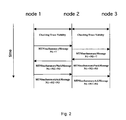
- Fig. 2 it is shown how this information can be obtained by a suitable discovery process.
- node 2 If for example node 1 and 2 of an MTN bus are busy with exchanging there service capabilities, node 2 must tell node 1 that it is also possible to reach node 3 on the bus. First node 1 knows from the status of its adaptation functions, that it is the first node on the bus. Then it sends an MTNbusSummaryMessage to node 2, which updates its status and passes a further MTNbusSummaryMessage to node 3, where the link to node 1 is already indicated. Node 3, as the last node on the bus sends an MTNbusSummaryNackMessage back to node 2 indicating which objects need to be changed to include the interface status at node 3.
- Node 2 updates its database and sends an MTNbusSummaryNackMessage to node 1 indicating the capabilities of node 2 and 3. Then node 1 can confirm the status by sending an MTNbusSummaryAckMessage to node 2, which sends a further MTNbusSummaryMessage to node 3.
- node 1 sends node 2 the information that it is the first on the bus and tells all interface mappings it has locally.
- each node collects information about its conditions and sends that information to the proximate node by the MTNbusSummaryMessage. If that message does not contain all or if it contains wrong parameter values about the MTN bus the receiving node responds with a MTNbusSummaryNackMessage which may include new values for the missing or wrong parameters. This negotiation of parameters may be forbidden by marking some parameters as non-negotiable in the MTNbusSummaryMessage or MTNbusSummaryNackMessage.
- each node Upon successful discovery of the MTN bus, each node receives a MTNbusSummaryAckMessage from the proximate nodes, indicating the identity of the parameter values held at there.
- each node that has been provided with information comprised in the MTNbusSummaryMessage provides its proximate node with information comprising the conditions of that particular node plus the conditions of all nodes information has been received from.
- the exchange of information follows a hierarchy beginning at the first node within the bus system.
- exchanging of the information begins from the first node to the last node forming the bus and vice versa. It is also thinkable that the nodes between the first and the last node immediately acknowledge the receipt of a particular information by sending back an information comprising the conditions discovered plus the conditions of other nodes received by similar information.
- the first node on the bus starts the process. However, if it does not, or if a node is added at the beginning of the bus, then there might be more than one MTN bus ID assigned. However, by exchanging the MTNbusSummaryMessage's one can agree on one common ID.
- the invention is commercially applicable particularly in the field of production and operation of multipoint transport networks for optical and/or electromagnetic data transmission.
Landscapes
- Engineering & Computer Science (AREA)
- Computer Networks & Wireless Communication (AREA)
- Signal Processing (AREA)
- Data Exchanges In Wide-Area Networks (AREA)
- Small-Scale Networks (AREA)
Abstract
Description
- The invention relates to a method for automatically discovering a bus system in a multipoint transport network, plus a multipoint transport network to be used to execute said method, plus a network node to be used in said multipoint transport. network.
- A network can be defined as a physical arrangement of network nodes that can be logical connected with each other by links.
- In a point-to-point network each node can be logical connected by a link with one or two adjacent nodes depending on if the node is the first or last node in a network or if it is lying in between the first and the last node. The node or the nodes a node can be logical connected with, is the one or are the two physical proximate nodes, one in each direction. So a point-to-point network can be seen as a physical one-dimensional arrangement of nodes that can be logically connected with one physically adjacent node in each direction. A bus system in a conventional point-to-point network is the sum of the one-dimensional logical connections, i.e. the links between aligned adjacent nodes. In a point-to-point network knowledge of the links between the nodes automatically leads to the knowledge of the bus system.
- With raising data traffic network architecture changes from point-to-point networks to multipoint transport networks (MTN). A MTN is not a one-dimensional arrangement of nodes but can be seen as a two-dimensional arrangement of a plurality of nodes. In a MTN each node potentially can be logical connected with a plurality of physically adjacent nodes. So a bus system in a MTN is not a simple addition of links between one-dimensionally aligned adjacent nodes because in a MTN a plurality of physical proximate nodes exists, each one potentially connectable with its proximate nodes by a link, wherein not necessarily each potential link leads to or is required for a desired bus system. Opposite to current point-to-point connections MTN busses provide a multipoint to multipoint connectivity, which will enhance the load of the network.
- For future transport of user data streams like e.g. Internet protocol (IP) data streams within MTN it is necessary to automatically discover bus systems that can be seen as a catenation of a number of links within said MTN. Up to now it is not possible to automatically discover a bus system in a MTN because it is not possible to know in advance which catenation of links provides the desired logical connection between a first and a last node.
- The technical purpose of the invention is to develop a method that allows automatically discovering a bus system in a multipoint transport network, plus a multipoint transport network to be used to execute said method, plus a network node of said multipoint transport network.
- The invention's technical purpose is met by the proposed method for automatically discovering a bus system in a MTN that is characterized in that the individual nodes of this network at first discover those conditions, which are directly accessible to them and then exchange and acknowledge said conditions along said bus.
- Thereby all nodes along the bus act in concert, wherein each node collects information about its conditions, sends that information to the proximate node and receives information about the conditions of the proximate node by an acknowledge message. Thereby the first node in the bus system can only collect information about its conditions and send this information to the second node. The second node when receiving the information from the first node provides the third node with information comprising the conditions of the first and the second node and so on. Doing so, the last node receives information comprising the conditions of all nodes along the bus. By sending an acknowledge message, the last node provides the information comprising the conditions of all nodes along the bus inclusive the last node to all nodes along the bus inclusive the first node. Doing so it is possible to automatically discover a bus system of a MTN in service. Thereby it is also thinkable that the first node confirms this acknowledge message of the last node that has been received by all nodes along the bus by a second acknowledge message that again will be received by all nodes.
- Said method with the specifying features of
claim 1 has the advantage over the state of the art, that it allows an automatic discovery process for MTN busses. It is characterized by an interworking of all nodes along the bus. - A preferred embodiment of said method according to the invention is characterized in that each node after discovering its conditions provides information comprising those conditions at least to the proximate nodes, wherein each node that has been provided with such information provides its proximate nodes with information comprising the conditions of that particular node plus the conditions of all nodes information has been received from.
- Another preferred embodiment of said method according to the invention is characterized in that exchanging information follows a hierarchy beginning at the first node within said bus system. Preferably exchanging of the information begins from the first node to the last node forming the bus and vice versa. It is also thinkable that the nodes between the first and the last node immediately acknowledge the receipt of a particular information by sending back an information comprising the conditions discovered plus the conditions of other nodes received by similar information.
- In a preferred embodiment of the invention each node acknowledges said information the very moment information comprising conditions of other nodes has been received.
- In a particular preferred embodiment of the invention, discovery of the conditions of the nodes takes place in the control plane. Automatic discovery is a key feature of the control plane. It can be used to discover the structure of any layer of the data plane. The MTN bus can be seen as a transport entity of the data plane. The data plane provides transfer of user data from one location to one or more other locations. The data plane is layered and comprises e.g. the Generic Framing Procedure (GFP) layer and the Optical Data Unit (ODU) layer. With the automatic discovery procedure it is possible to check the data plane against the control plane.
- An additional preferred embodiment of said method according to the invention is characterized in that to discover the conditions of at least one potential link connection between the nodes the data plane is checked against the control plane. Thereby the invention deals with the process for in service layer adjacency discovery for MTN busses. Hereby layer adjacency discovery is defined as a process for deriving an association between two sub-network termination points (SNTP) that form a potential link connection in a particular layer network. The purpose of layer adjacency discovery is to derive all association between two SNTPs that form a potential client layer link connection and are supported by the MTN bus. As the MTN bus can be seen as a number of links from the higher layer perspective, this process will detect all of them, which are able to carry link connections. The term 'in service' relates to the fact that the discovery process is performed in parallel to the user data transfer wherein the information required for discovery is carried in the trail overhead.
- A particularly preferred embodiment of said invention is characterized in that a test signal is placed in the GFP layer overhead by the termination functions, to gain a relation between the termination functions and the corresponding termination connection points. This in-band test signal comprises a Termination Connection Point (TCP) identifier of the originating termination function and the control plane address of a discovery agent, located in the control plane, which is concerned with the control of the originating termination function. Upon reception of the test signal at the corresponding termination functions, the receiving node starts to build up a control channel between the discovery agents of the nodes on the control plane. By exchanging Trace Monitor Messages the identity of the test signal placed in the overhead is compared with a trace message specified in the Trace Monitor Message. Thereby it is possible to separate the control plane identifiers from the data plane identifiers. This is compliant to current standards. In a further step the relations between the connection points of the MTN bus are derived by using local knowledge about the status of the adaptation functions.
- According to a preferred embodiment of said method according to the invention the Link Management Protocol (LMP) of the control plane is used to detect a bus system in said MTN, wherein to tackle MTN busses the LMP is changed.
- In a preferred embodiment of said invention, the MTN bus is realized in a GFP layer that is set upon an ODU layer.
- In another preferred embodiment of the invention, said method is performed by a MTN, comprising means to automatically discover the conditions at least of the nodes along the bus and means to exchange information between said nodes, wherein said information comprises said conditions.
- Another preferred embodiment of said invention concerns a network node for a MTN, wherein said network node comprises means to automatically discover its conditions, means to receive similar information from other nodes and means to provide other nodes within said multipoint transport network with information comprising at least the conditions discovered and the information received.
-
- Fig. 1
- showing a scheme of in-service discovery for MTN busses, and
- Fig. 2
- showing a sequence diagram of the MTN bus discovery.
- This invention deals with the process for in-service layer adjacency discovery for MTN busses. Layer adjacency discovery is defined as a process for deriving an association between two sub-network termination points (SNTP), which form a potential client layer link connection in a particular layer network. As the MTN bus is seen as a number of links from the higher layer perspective, this process will detect all of them, which are able to carry link connections. The term 'in-service' relates to the fact that the discovery process is performed in parallel to the user data transfer with the discovery information carried in the trail overhead. In Fig. 1 the MTN bus is realized in the
GFP layer 200, which is set-up on anODU layer 100. - Thereby the lower part of Fig. 1 comprising the ODU handling is completely standard conform (ODU layer 100). On the left side there is an
ODU sub network 110 shown with two adjacent ODU termination functions 111, 112. Thesub network 110 carries an ODUlayer network connection 113. Above the termination functions 111, 112 there are theODU access points access points ODU trail 116. The ODU adaptation functions 117, 118 together with theODU trail 116 form a link in the topology of theGFP layer 200. This link, together with a link on the right side of the diagram, which is constructed in the same manner (ODU sub network 120, termination functions 121, 122, ODUlayer network connection 123,ODU access points ODU trail 126, ODU adaptation functions 127, 128) andGFP sub networks 210 are used for a set-up of the MTN bus. - In the GFP layer overhead a test signal is placed by the GFP termination functions 221, 222, 223 to automatically discover a bus system. So first a
relation 300 between all GFP termination functions 221, 222, 223 and the corresponding termination connection points 10 is gained. - From this the
relations 400 between all connection points 20 of the MTN bus are derived by using local knowledge about the status of the GFP adaptation functions 224, 225, 226. This inference needs a communication between allnodes - With the normal discovery of link connections the Link Management Protocol (LMP) is used for this purpose. Here some adaptations are required.
- Thereby, in a first step the Termination Connection Point (TCP) to TCP relations have to be detected, which the standard LMP can be used for. But the discovery process needs to be adapted, which is also part of this invention.
- Things become more complicated when the client
layer link connection 400 needs to be inferred in a second step. This is normally done by the exchange of the LinkSummary messages, which is a service capability exchange and is part of the LMP. - Clearly here significant adaptations need to be performed. The following parameters were identified as required information at the end of the discovery process at each node.
- The first parameter to be adapted comprises the MTN bus ID. All nodes need to know that they are part of a certain MTN bus, and thus a MTN bus ID is required that has to be unique for all involved nodes.
- The second parameter to be adapted comprises the MTN bus server links. Thereby it is important that it must be known to all nodes which links on the server layer, e.g. the GFP-
layer 200 in Fig. 1, are forming the bus. Implicitly, then also the placement of the nodes along the bus is known, which is required for the right initialization of the MTN bus, especially the handling of the time to drop counters (TTD). - The third parameter to be adapted comprises the MTN bus client links. The MTN bus client links are the SNTP to
SNTP relations 400, that are the outcome of the discovery process. - Now in a third step a new MTNbusSummaryMessage is formed that has to contain all these parts.
- In Fig. 2 it is shown how this information can be obtained by a suitable discovery process.
- If for
example node node 2 must tellnode 1 that it is also possible to reachnode 3 on the bus.First node 1 knows from the status of its adaptation functions, that it is the first node on the bus. Then it sends an MTNbusSummaryMessage tonode 2, which updates its status and passes a further MTNbusSummaryMessage tonode 3, where the link tonode 1 is already indicated.Node 3, as the last node on the bus sends an MTNbusSummaryNackMessage back tonode 2 indicating which objects need to be changed to include the interface status atnode 3.Node 2 updates its database and sends an MTNbusSummaryNackMessage tonode 1 indicating the capabilities ofnode node 1 can confirm the status by sending an MTNbusSummaryAckMessage tonode 2, which sends a further MTNbusSummaryMessage tonode 3. - The contents of the messages are depicted by for example "N1-> ?". This means that
node 1 sendsnode 2 the information that it is the first on the bus and tells all interface mappings it has locally. - Doing so, all nodes along the bus act in concert, wherein each node collects information about its conditions and sends that information to the proximate node by the MTNbusSummaryMessage. If that message does not contain all or if it contains wrong parameter values about the MTN bus the receiving node responds with a MTNbusSummaryNackMessage which may include new values for the missing or wrong parameters. This negotiation of parameters may be forbidden by marking some parameters as non-negotiable in the MTNbusSummaryMessage or MTNbusSummaryNackMessage. Upon successful discovery of the MTN bus, each node receives a MTNbusSummaryAckMessage from the proximate nodes, indicating the identity of the parameter values held at there.
- Thereby each node that has been provided with information comprised in the MTNbusSummaryMessage provides its proximate node with information comprising the conditions of that particular node plus the conditions of all nodes information has been received from.
- Preferably the exchange of information follows a hierarchy beginning at the first node within the bus system. Preferably exchanging of the information begins from the first node to the last node forming the bus and vice versa. It is also thinkable that the nodes between the first and the last node immediately acknowledge the receipt of a particular information by sending back an information comprising the conditions discovered plus the conditions of other nodes received by similar information.
- It is best, if the first node on the bus starts the process. However, if it does not, or if a node is added at the beginning of the bus, then there might be more than one MTN bus ID assigned. However, by exchanging the MTNbusSummaryMessage's one can agree on one common ID.
- To finally establish the bus system, preferably potential link connections between physically adjacent nodes are chosen, between which nodes no or only few data traffic takes place the very moment automatic discovery of the bus system takes place.
- The invention is commercially applicable particularly in the field of production and operation of multipoint transport networks for optical and/or electromagnetic data transmission.
-
- 1,2,3
- node
- 10
- termination connection point (TCP)
- 20
- connection point
- 100
- ODU-layer
- 110, 120
- ODU sub network
- 111, 112, 121, 122
- ODU termination function
- 113, 123
- ODU layer network connection
- 114, 115, 124, 125
- ODU access point
- 116, 126
- ODU trail
- 117, 118, 127, 128
- ODU adaptation function
- 200
- GFP layer
- 210
- GFP sub network
- 221, 222, 223
- GFP termination functions
- 224, 225, 226
- GFP adaptation function
- 300
- relation
- 400
- client layer link connection
Claims (11)
- Method for automatically discovering a bus system in a multipoint transport network, characterized in that the individual nodes (1, 2, 3) of this network at first discover those conditions, which are directly accessible to them and then exchange and acknowledge said conditions along said bus.
- Method according to claim 1, characterized in that each node (1, 2, 3) after discovering its conditions provides information comprising those conditions at least to the proximate nodes (1, 2, 3), wherein each node (1, 2, 3) that has been provided with such information provides its proximate nodes (1, 2, 3) with information comprising the conditions of that particular node (1, 2, 3) plus the conditions of all nodes (1, 2, 3) information has been received from.
- Method according to claim 1 or 2, characterized in that exchanging information follows a hierarchy beginning at the first node (1) within said bus system.
- Method according to claim 2 or 3, characterized in that each node (1, 2, 3) acknowledges said information the very moment information comprising conditions of other nodes (1, 2, 3) has been received.
- Method according to one of the previous claims, wherein discovery of the conditions of the nodes (1, 2, 3) takes place in the control plane.
- Method according to claim 5, characterized in that to discover the conditions of at least one potential connection (400) between the nodes (1, 2, 3) the data plane is checked against the control plane.
- Method according to claim 6, characterized in that a test signal is placed to gain a relation (300) between the termination functions (221, 222, 223) and the corresponding termination connection points (10), wherein the relations (400) between the connection points (20) of the MTN bus are derived by using local knowledge about the status of the adaptation functions (224, 225, 226).
- Method according to one of the claims 5 to 7, wherein to establish a bus system in said multipoint transport network, the link management protocol of the control plane is used.
- Method according to one of the previous claims, wherein the MTN bus is realized in a GFP layer (200) that is set upon an ODU layer (100).
- Multipoint transport network for carrying out the method according to one of the previous claims, comprising means to automatically discover the conditions of the nodes (1, 2, 3) along the bus and means to exchange information between said nodes (1, 2, 3), wherein said information comprises said conditions.
- Network node (1, 2, 3) for a multipoint transport network according to claim 10, comprising means to discover its conditions, means to receive similar information from other nodes (1, 2, 3) and means to provide other nodes (1, 2, 3) within said multipoint transport network with information comprising at least the conditions discovered and the information received.
Priority Applications (3)
| Application Number | Priority Date | Filing Date | Title |
|---|---|---|---|
| EP05292255A EP1780942A1 (en) | 2005-10-25 | 2005-10-25 | Method for automatically discovering a bus system in a multipoint transport network, multipoint transport network and network node |
| US11/584,627 US7764630B2 (en) | 2005-10-25 | 2006-10-23 | Method for automatically discovering a bus system in a multipoint transport network, multipoint transport network and network node |
| CNA200610137156XA CN1956406A (en) | 2005-10-25 | 2006-10-24 | Method for automatic discovery of bus system in multipoint transmission network and multipoint transmission network |
Applications Claiming Priority (1)
| Application Number | Priority Date | Filing Date | Title |
|---|---|---|---|
| EP05292255A EP1780942A1 (en) | 2005-10-25 | 2005-10-25 | Method for automatically discovering a bus system in a multipoint transport network, multipoint transport network and network node |
Publications (1)
| Publication Number | Publication Date |
|---|---|
| EP1780942A1 true EP1780942A1 (en) | 2007-05-02 |
Family
ID=35448030
Family Applications (1)
| Application Number | Title | Priority Date | Filing Date |
|---|---|---|---|
| EP05292255A Withdrawn EP1780942A1 (en) | 2005-10-25 | 2005-10-25 | Method for automatically discovering a bus system in a multipoint transport network, multipoint transport network and network node |
Country Status (3)
| Country | Link |
|---|---|
| US (1) | US7764630B2 (en) |
| EP (1) | EP1780942A1 (en) |
| CN (1) | CN1956406A (en) |
Families Citing this family (3)
| Publication number | Priority date | Publication date | Assignee | Title |
|---|---|---|---|---|
| KR101207569B1 (en) * | 2008-04-22 | 2012-12-03 | 삼성전자주식회사 | Apparatus and method for selection of precoding vector |
| ATE556507T1 (en) * | 2009-09-14 | 2012-05-15 | Alcatel Lucent | METHOD AND DEVICE FOR AUTOMATIC DETECTION IN OPTICAL TRANSPORT NETWORKS |
| CN102202246B (en) * | 2010-03-25 | 2014-11-05 | 中兴通讯股份有限公司 | G.709-based end-to-end service establishment method, system and optical transport network |
Citations (1)
| Publication number | Priority date | Publication date | Assignee | Title |
|---|---|---|---|---|
| WO2000052890A1 (en) * | 1999-03-01 | 2000-09-08 | Ciena Corporation | Routing and signaling in a sonet network |
Family Cites Families (5)
| Publication number | Priority date | Publication date | Assignee | Title |
|---|---|---|---|---|
| US20050089027A1 (en) * | 2002-06-18 | 2005-04-28 | Colton John R. | Intelligent optical data switching system |
| US20040073717A1 (en) * | 2002-10-14 | 2004-04-15 | Linda Cline | System method and device for dynamic mapping of sonet paths |
| US7385998B2 (en) * | 2003-09-08 | 2008-06-10 | Nortel Networks Limited | Method and apparatus for encapsulating services for transportation over metallic physical mediums |
| CN1311673C (en) * | 2003-12-03 | 2007-04-18 | 华为技术有限公司 | Method for transmitting multi-protocol tag exchange protocol data unit |
| CN1780193B (en) * | 2004-11-25 | 2010-08-11 | 华为技术有限公司 | Add-drop multiplexing method, device and system based on general framing procedure |
-
2005
- 2005-10-25 EP EP05292255A patent/EP1780942A1/en not_active Withdrawn
-
2006
- 2006-10-23 US US11/584,627 patent/US7764630B2/en not_active Expired - Fee Related
- 2006-10-24 CN CNA200610137156XA patent/CN1956406A/en active Pending
Patent Citations (1)
| Publication number | Priority date | Publication date | Assignee | Title |
|---|---|---|---|---|
| WO2000052890A1 (en) * | 1999-03-01 | 2000-09-08 | Ciena Corporation | Routing and signaling in a sonet network |
Non-Patent Citations (2)
| Title |
|---|
| "ITU-T G.7714 / Y.1705 Generalized automatic discovery for Transport Entities", ITU-T SERIES G: TRANSMISSION SYSTEM AND MEDIA, DIGITAL SYSTEMS AND NETWORKS; SERIES Y: GLOBAL INFORMATION INFRASTRUCTURE, INTERNET PROTOCOL ASPECTS AND NEXT-GENERATION NETWORKS, August 2005 (2005-08-01), XP002359033, Retrieved from the Internet <URL:http://mirror.itu.int/dms/pay/itu-t/rec/g/T-REC-G.7714-200508-P!!PDF-E.pdf> [retrieved on 20051214] * |
| IEEE 802.1AB WORKING GROUP: "IEEE 802.1AB: Station and Media Access Control Connectivity Discovery", IEEE 802.1AB IEEE STANDARD FOR LOCAL AND METROPOLITAN AREA NETWORKS, 6 May 2005 (2005-05-06), New York, NY, USA, pages I - 57, XP002359034, Retrieved from the Internet <URL:http://ieeexplore.ieee.org/iel5/9971/32029/01490127.pdf?isnumber=32029&prod=STD&arnumber=1490127&arSt=+0_1&ared=+158&arAuthor=> [retrieved on 20051214] * |
Also Published As
| Publication number | Publication date |
|---|---|
| US7764630B2 (en) | 2010-07-27 |
| US20070115854A1 (en) | 2007-05-24 |
| CN1956406A (en) | 2007-05-02 |
Similar Documents
| Publication | Publication Date | Title |
|---|---|---|
| EP1542409B1 (en) | Protocol for multi-hop ad-hoc networks | |
| US9413650B2 (en) | Lightweight control-plane signaling for aggregation devices in a network | |
| US10362123B2 (en) | System and method for endpoint discovery based on data distribution service | |
| US6654350B1 (en) | Method and apparatus for tracking a transaction across a multi-hop network | |
| JP2002531003A (en) | Method and system for determining network topology | |
| CN110601989A (en) | Network traffic balancing method and device | |
| US12074758B2 (en) | Method for configuring a terminal device | |
| EP3754933B1 (en) | Fault diagnosis method and apparatus therefor | |
| EP1780942A1 (en) | Method for automatically discovering a bus system in a multipoint transport network, multipoint transport network and network node | |
| CN100490394C (en) | Method and apparatus for detecting topology of network | |
| EP1538777A1 (en) | Configuration management device for a self-configurable network equipment of a communication network provided with equipment configuration parameter consistency analysis module | |
| JP3293719B2 (en) | Network management system | |
| JP2003507976A (en) | Comprehensive alignment process in multi-manager environment | |
| US20070230458A1 (en) | Communication Network, Communication Apparatus, Communication Control Method and Communication Control Program | |
| WO2005039125A1 (en) | Home link setting method, home gateway device, and mobile terminal | |
| JP2002538671A (en) | Data transmission to network management system | |
| JP2001067291A (en) | Network monitor system | |
| JP2023180787A (en) | Communication device, communication setting method, and program | |
| JP5040862B2 (en) | SCTP association aggregation apparatus, communication system including the apparatus, and routing method | |
| CN108989168A (en) | Method and apparatus for being identified in a computer network | |
| US7110364B1 (en) | Optical link adjacency discovery protocol and an optical network therefor | |
| CN101197755B (en) | A method and device for transmitting SUA signaling network management messages | |
| KR101740799B1 (en) | Method of failover for network service in software defined networking environment | |
| CN114666313B (en) | Parameter acquisition method, server, terminal and readable storage medium | |
| CN101895559B (en) | Method for passing through network and firewall for agency |
Legal Events
| Date | Code | Title | Description |
|---|---|---|---|
| PUAI | Public reference made under article 153(3) epc to a published international application that has entered the european phase |
Free format text: ORIGINAL CODE: 0009012 |
|
| 17P | Request for examination filed |
Effective date: 20060215 |
|
| AK | Designated contracting states |
Kind code of ref document: A1 Designated state(s): AT BE BG CH CY CZ DE DK EE ES FI FR GB GR HU IE IS IT LI LT LU LV MC NL PL PT RO SE SI SK TR |
|
| AX | Request for extension of the european patent |
Extension state: AL BA HR MK YU |
|
| AKX | Designation fees paid |
Designated state(s): AT BE BG CH CY CZ DE DK EE ES FI FR GB GR HU IE IS IT LI LT LU LV MC NL PL PT RO SE SI SK TR |
|
| GRAP | Despatch of communication of intention to grant a patent |
Free format text: ORIGINAL CODE: EPIDOSNIGR1 |
|
| STAA | Information on the status of an ep patent application or granted ep patent |
Free format text: STATUS: THE APPLICATION IS DEEMED TO BE WITHDRAWN |
|
| 18D | Application deemed to be withdrawn |
Effective date: 20110414 |