EP1780862A2 - Power supply system - Google Patents
Power supply system Download PDFInfo
- Publication number
- EP1780862A2 EP1780862A2 EP06022179A EP06022179A EP1780862A2 EP 1780862 A2 EP1780862 A2 EP 1780862A2 EP 06022179 A EP06022179 A EP 06022179A EP 06022179 A EP06022179 A EP 06022179A EP 1780862 A2 EP1780862 A2 EP 1780862A2
- Authority
- EP
- European Patent Office
- Prior art keywords
- power
- primary core
- load devices
- cores
- protrusions
- Prior art date
- Legal status (The legal status is an assumption and is not a legal conclusion. Google has not performed a legal analysis and makes no representation as to the accuracy of the status listed.)
- Withdrawn
Links
Images


Classifications
-
- H—ELECTRICITY
- H02—GENERATION; CONVERSION OR DISTRIBUTION OF ELECTRIC POWER
- H02J—CIRCUIT ARRANGEMENTS OR SYSTEMS FOR SUPPLYING OR DISTRIBUTING ELECTRIC POWER; SYSTEMS FOR STORING ELECTRIC ENERGY
- H02J50/00—Circuit arrangements or systems for wireless supply or distribution of electric power
- H02J50/40—Circuit arrangements or systems for wireless supply or distribution of electric power using two or more transmitting or receiving devices
- H02J50/402—Circuit arrangements or systems for wireless supply or distribution of electric power using two or more transmitting or receiving devices the two or more transmitting or the two or more receiving devices being integrated in the same unit, e.g. power mats with several coils or antennas with several sub-antennas
-
- H—ELECTRICITY
- H01—ELECTRIC ELEMENTS
- H01F—MAGNETS; INDUCTANCES; TRANSFORMERS; SELECTION OF MATERIALS FOR THEIR MAGNETIC PROPERTIES
- H01F38/00—Adaptations of transformers or inductances for specific applications or functions
- H01F38/14—Inductive couplings
-
- H—ELECTRICITY
- H02—GENERATION; CONVERSION OR DISTRIBUTION OF ELECTRIC POWER
- H02J—CIRCUIT ARRANGEMENTS OR SYSTEMS FOR SUPPLYING OR DISTRIBUTING ELECTRIC POWER; SYSTEMS FOR STORING ELECTRIC ENERGY
- H02J50/00—Circuit arrangements or systems for wireless supply or distribution of electric power
- H02J50/10—Circuit arrangements or systems for wireless supply or distribution of electric power using inductive coupling
- H02J50/12—Circuit arrangements or systems for wireless supply or distribution of electric power using inductive coupling of the resonant type
-
- H—ELECTRICITY
- H02—GENERATION; CONVERSION OR DISTRIBUTION OF ELECTRIC POWER
- H02J—CIRCUIT ARRANGEMENTS OR SYSTEMS FOR SUPPLYING OR DISTRIBUTING ELECTRIC POWER; SYSTEMS FOR STORING ELECTRIC ENERGY
- H02J7/00—Circuit arrangements for charging or depolarising batteries or for supplying loads from batteries
- H02J7/02—Circuit arrangements for charging or depolarising batteries or for supplying loads from batteries for charging batteries from ac mains by converters
-
- H—ELECTRICITY
- H01—ELECTRIC ELEMENTS
- H01F—MAGNETS; INDUCTANCES; TRANSFORMERS; SELECTION OF MATERIALS FOR THEIR MAGNETIC PROPERTIES
- H01F3/00—Cores, Yokes, or armatures
-
- H—ELECTRICITY
- H01—ELECTRIC ELEMENTS
- H01F—MAGNETS; INDUCTANCES; TRANSFORMERS; SELECTION OF MATERIALS FOR THEIR MAGNETIC PROPERTIES
- H01F30/00—Fixed transformers not covered by group H01F19/00
- H01F30/04—Fixed transformers not covered by group H01F19/00 having two or more secondary windings, each supplying a separate load, e.g. for radio set power supplies
-
- H—ELECTRICITY
- H02—GENERATION; CONVERSION OR DISTRIBUTION OF ELECTRIC POWER
- H02J—CIRCUIT ARRANGEMENTS OR SYSTEMS FOR SUPPLYING OR DISTRIBUTING ELECTRIC POWER; SYSTEMS FOR STORING ELECTRIC ENERGY
- H02J50/00—Circuit arrangements or systems for wireless supply or distribution of electric power
- H02J50/005—Mechanical details of housing or structure aiming to accommodate the power transfer means, e.g. mechanical integration of coils, antennas or transducers into emitting or receiving devices
-
- H—ELECTRICITY
- H02—GENERATION; CONVERSION OR DISTRIBUTION OF ELECTRIC POWER
- H02J—CIRCUIT ARRANGEMENTS OR SYSTEMS FOR SUPPLYING OR DISTRIBUTING ELECTRIC POWER; SYSTEMS FOR STORING ELECTRIC ENERGY
- H02J50/00—Circuit arrangements or systems for wireless supply or distribution of electric power
- H02J50/70—Circuit arrangements or systems for wireless supply or distribution of electric power involving the reduction of electric, magnetic or electromagnetic leakage fields
Definitions
- the present invention relates to a power supply system capable of feeding electric power from a single power adaptor to a plurality of load devices and, more specifically, to a power supply system in which a power feeding operation is performed by contactless power transmission based on electromagnetic induction.
- FIGs. 21A and 21B show configurations of a power supply system for use in the electric shaver.
- an electric shaver 2 can be connected to a power adapter 1 which is formed of a RCC (ringing choke converter) and the like.
- a cleaning device 3 can also be connected to the power adapter 1.
- the power adapter 1 since the power adapter 1 is outputting a direct current of, e.g., 12V, the task of feeding electric power to a cleaning device driving circuit 4 in the cleaning device 3 and the task of charging the electric shaver 2 mounted on the cleaning device 3 are performed through branch lines just in that condition.
- the power adapter 1 needs to be connected to the cleaning device 3 or the electric shaver 2 by way of a contacting type contact point 5.
- the electric shaver 2 due to the fact that the power adapter 1 is feeding electric power of a voltage as high as 12V to match the cleaning device 3 of high power consumption, the electric shaver 2 requires the use of a step-down power converter 7 for dropping the voltage to a level suitable for charging a secondary battery 6.
- the electric shaver 2 grows in size.
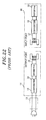
- Fig. 22 illustrates a conventional power supply system by which power feeding is conducted in a contactless manner.
- a commercial alternating current inputted to a power adapter 12 through a power cord 11 is converted to a direct current in a converter 13.
- the direct current is converted to a high frequency alternating current in a voltage-resonant inverter 14 and then outputted from a primary coil 15 which is an output port of the power adapter 12.
- the primary coil 15 is magnetically coupled in a detachable manner to a secondary coil 17 which is an input port of an electric shaver 16.
- the alternating voltage developed in the secondary coil 17 is converted to a direct voltage in a converter circuit 18 and then fed to a load 19 which is formed of a secondary battery and an electric motor.
- the converter circuit 18 is an A/D converter whose size is smaller than that of a DC-DC converter of the step-down power converter 7 noted above.
- Figs. 23A and 23B are provided if the contactless power supply system illustrated in Fig. 22 is applied to the power supply system shown in Figs. 21A and 21B, to which a plurality of load devices including the cleaning device 3 is connectable.
- a power adapter 21 which is formed of a voltage-resonant inverter and so forth, serves to output an alternating current of, e.g., 50kHz and 30V, to a power transmission coil 24.
- a power receiving coil 25 of an electric shaver 22 can be connected in a contactless manner to the power transmission coil 24 as shown in Fig. 23A.
- a power receiving coil 26 of a cleaning device 23 can be connected in a contactless manner to the power transmission coil 24 as shown in Fig. 23B.
- an A/D converter 27 is provided in the cleaning device 23.
- the A/D converter 27 is adapted to generate, e.g., a direct current of 12V, and feed the same to a cleaning device driving circuit 28.
- an inverter 29 formed of a voltage-resonant inverter and the like for outputting an alternating current of, e.g., 50kHz and 30V, and a power transmission coil 30 are provided in the cleaning device 23.
- one example of parallel power feeding techniques using electromagnetic induction is disclosed in, e.g., Japanese Laid-open Application H3-101110A .
- the prior art reference is directed to an electromagnetic outlet socket device in which a plurality of primary coils serving as a socket body are embedded into a wall in parallel and a load-connected secondary coil serving as a socket cap is fitted into the socket body, thereby making it possible to simultaneously feed electric power to a plurality of loads in parallel and in a contactless fashion. Therefore, the prior art reference teaches nothing but a structure of electromagnetic coupling parts.
- the converter 27 and the inverter 29 need to be additionally provided in the cleaning device 23 for the purpose of realizing a contactless power feeding operation. This leads to an increase in size and costs.
- a power supply system for feeding electric power from a power adapter to a plurality of load devices
- the power adapter includes a primary core; and a primary coil wound around the primary core for serving as a output port of the power adapter to output an alternating current
- the load devices include secondary cores for simultaneously forming magnetic circuits between the primary core and the load devices; and secondary coils wound around the secondary cores for feeding output power to the load devices.
- the load devices are provided with secondary cores capable of forming magnetic circuits with the primary core and secondary coils wound around the secondary cores. This makes it possible to generate output power to be fed.
- the cores are formed into such a shape as to simultaneously form magnetic circuits on a load device basis, thereby making it possible to perform a parallel power feeding operation.
- the input ports of the plurality of load devices can be connected to the output port of the single power adapter to thereby perform a parallel power feeding operation.
- a power conversion unit such as a converter or an inverter
- the primary core has two pairs of protrusions, each of the pairs of the protrusions extending in a same direction, and one of the pairs of the protrusions oriented in an opposite direction with respect to the other of the pairs of the protrusions, and he secondary cores, each of which has a pair of protrusions extending in a same direction, are arranged on opposite sides of the primary core in such a manner that the primary core lies between the secondary cores to feed electric power simultaneously to the load devices.
- electric power can be fed to two load devices with a simple structure by adopting a three-stage stack structure in which the secondary cores are arranged on opposite sides of the primary core in such a manner that the primary core lie between the secondary cores.
- the primary core has two pairs of protrusions and a shaft portion wound with the primary coil, each of the pairs of protrusions extending in a same direction from the shaft portion, and one of the pairs of protrusions oriented in an orthogonal direction with respect to the other of the pairs of protrusions.
- each of the secondary cores has two pairs of protrusions, each of the pairs of protrusions extending in a same direction, and the secondary cores arranged in such a manner that the secondary cores form an "L"-shape with the primary core when viewed from an axial direction of the shaft portion to feed electric power simultaneously to the load devices.
- two secondary cores are arranged so as to form an "L"-like shape with a primary core.
- the primary core can be placed in close proximity with the secondary cores received in the respective load devices.
- the primary core is formed in a bobbin shape and the secondary cores are formed in a square bracket shape, the secondary cores arranged in plural numbers around the primary core in such a manner that opposite ends of the secondary cores face flanges of the primary core to feed electric power simultaneously to the load devices.
- the flanges of a bobbin are allowed to serve as protrusions extending from the primary core toward the secondary cores.
- magnetic paths can be formed by merely arranging the secondary cores around the primary core. This means that the secondary cores can be arranged in the number decided by the diameter or the like of the secondary coils wound around the center portion of the square-bracket-shaped secondary cores.
- an electric shaver serves as a first load device of the load devices, and a cleaning device used for the electric shaver serves as a second load device of the load devices. Further, the electric shaver is to be fed with the electric power directly from the power adapter and to be electrically charged in a state that the electric shaver is mounted on the cleaning device.
- the power supply system of the present invention makes it possible to feed electric power from a single power adapter to a plurality of load devices separately or simultaneously.
- a high frequency alternating current is used as an output power
- the primary core and the primary coil wound around the primary core are used as an output port.
- the load devices are provided with secondary cores capable of forming magnetic circuits with the primary core and secondary coils wound around the secondary cores. This makes it possible to generate output power to be fed.
- the cores are formed into such a shape as to simultaneously form magnetic circuits on a load device basis, thereby making it possible to perform a parallel power feeding operation.
- the input ports of the plurality of load devices can be connected to the output port of the single power adapter to thereby perform a parallel power feeding operation.
- a power conversion unit such as a converter or an inverter
- Figs. 1A to 2B show configurations of a power supply system in accordance with a first embodiment of the present invention.
- the power supply system is for use in an electric shaver with a cleaning device.
- an electric shaver 32 can be connected to a single power adapter 31 or 31a.
- a cleaning device 33 can also be connected to the power adapter 31 or 31a. Referring to Figs. 1B and 2B, it is possible not only to cleanse a knife edge of the electric shaver 32 but also to electrically charge the electric shaver 32 under the state that the electric shaver 32 is mounted on the cleaning device 33.
- the power adapter 31 or 31a includes a converter 34, which is formed of a diode bridge, a smoothing capacitor and the like, and a voltage-resonant inverter 35.
- the power adapter 31 or 31a is adapted to output an alternating current of, e.g., 50kHz and 30V, to a power transmission coil 37 of a single power feeding plug 36 that serves as an output port and constitutes a primary coil of a transformer.
- a power receiving coil 38 of the electric shaver 32 that serves as an input port and constitutes a secondary coil of the transformer can be connected to the power transmission coil 37 in a contactless manner as illustrated in Figs. 1A, 1B, 2A and 2B.
- a power receiving coil 39 of the cleaning device 33 can also be connected to the power transmission coil 37 in a contactless manner as illustrated in Figs. 1B and 2B.
- the converter 34 and the voltage-resonant inverter 35 are configured integrally in the power adapter 31 shown in Figs. 1A and 1B .
- This configuration is suitable for a case where a power cable 40 extends relatively short between the power adapter 31 and the electric shaver 32 or the cleaning device 33.
- a high frequency current flows through the power cable 40.
- an inverter of a power supply device is of a resonance type, it generates a sinusoidal or trapezoidal voltage waveform with a reduced noise component. This makes it possible to reduce the radiation noise generated in a power cable which extends a long distance and the radiation noise caused by a magnetic field which is leaked in a small amount from a coil part for electromagnetic induction coupling. Accordingly, it is possible to get rid of an anti-noise part.
- the converter 34 and the voltage-resonant inverter 35 are configured separately in the power adapter 31a shown in Figs. 2A and 2B. This configuration helps to avoid radiation of a high frequency wave and is suitable for a case where a power cable 40a extends relatively long.
- a direct current of, e.g., 12V, is adapted to flow through the power cable 40a.
- a load circuit 41 formed of a secondary battery, an electric motor and the like
- a step-down power converter 42 formed of an A/D converter and adapted to generate a direct current of, e.g., 3V, suitable for use in the load circuit 41, by use of the alternating current generated in the power receiving coil 38.
- a cleaning device driving circuit 43 biased with the alternating current generated in the power receiving coil 39 is provided in the cleaning device 33.
- Fig. 3 is a block diagram illustrating an electric configuration of the power supply system shown in Figs. 1A and 1B. Parts corresponding to those of the configuration shown in Figs. 1A and 1B will be designated by like reference numerals, with no description given in that respect.
- the power transmission coil 37 serving as a primary coil is wound around a primary core 47 made of a magnetic material.
- the power receiving coil 38 serving as a secondary coil is wound around a secondary core 48 made of a magnetic material.
- the power receiving coil 39 serving as a secondary coil is wound around a secondary core 49 made of a magnetic material. In this way, the secondary cores 48 and 49 are connected to the primary core 47 in parallel through magnetic flux, thereby performing the contactless power transmission based on electromagnetic induction.
- the electric shaver 32 includes a converter 51 serving as the step-down power converter 42, a load circuit 52, such as an electric motor and the like, connected to the converter 51, a converter 53 arranged in parallel with the converter 51, and a load circuit 54, such as a microcomputer and the like, driven by the converter 53.
- the cleaning device 33 includes a converter 55, a load circuit 56, such as a cleaning water pumping motor, a drying fan, a drying-purpose induction heating circuit and the like, connected to the converter 55, a converter 57 arranged in parallel with the converter 55, and a load circuit 58, such as a microcomputer and the like, driven by the converter 57.
- the power transmission coil 37 of the power adapter 31 or 31a lies in proximity with both of the power receiving coils 38 and 39 to perform a parallel power feeding operation under the state that the electric shaver 32 is mounted on the cleaning device 33, as illustrated in Figs. 1B and 2B.
- the cleaning device 33 is provided with a slot 59a for reception of the power feeding plug 36 of a plate shape.
- the power receiving coil 38 in the cleaning device 33 is attached to the back side of the slot 59a within a nonmagnetic casing 59b.
- the power receiving coil 38 is arranged within a nonmagnetic casing 59c so that it can face the power feeding plug 36 when the electric shaver 32 is mounted on the cleaning device 33.
- Figs. 4 through 9 show the structures of the individual coils 37, 38 and 39 wound around the cores 47, 48 and 49.
- a primary core 47a forms magnetic circuits with a plurality of independently arranged secondary cores 48a and 49a.
- the primary core 47a is formed into an "I"-like shape and has two pairs of protrusions 59 and 60, each of the pairs of protrusions extending in the same direction, one of the pairs of protrusions oriented in the opposite direction with respect to the other.
- each of the secondary cores 48a and 49a is formed into a square bracket shape and has a pair of protrusions 61 or 62 extending in the same direction.
- the respective protrusions 59 and 60 of the primary core 47a are arranged to face the corresponding protrusions 61 and 62 of the secondary cores 48a and 49a, thus forming magnetic circuits.
- the protrusions 59 and 60 are greater in cross-sectional area than the protrusions 61 and 62 so as to realize a high magnetic coupling ratio, thereby providing a system that exhibits enhanced power transmission efficiency.
- a three-stage stack structure wherein the secondary cores 48a and 49a serving as two input port cores of the load devices are arranged on the opposite sides of the primary core 47a serving as an output port core.
- the power feeding plug 36 is inserted between the cleaning device 33 and the electric shaver 32.
- secondary cores 48b and 49b are formed into an "E"-like shape to have three protrusions 63 and 64.
- a primary core 47b is shaped to have a plurality of protrusions 65 and 66 that face the protrusions 63 and 64 of the "E"-like secondary cores 48b and 49b to form magnetic circuits.
- the primary coil 37 is divided into two coils 37a and 37b.
- This configuration also ensures that a high magnetic coupling ratio is achieved between the primary core 47b serving as an output port core and the secondary cores 48b and 49b serving as two input port cores of the load devices, while realizing a three-stage stack structure.
- cores 47c, 48c and 49c are of a cylindrical shape or a rectangular column shape (cylindrical shape in Fig. 6) and coils 37, 38 and 39 are wound around the outer circumferences of the cores 47c, 48c and 49c.
- the cores 47c, 48c and 49c are arranged rectilinearly in an end-to-end relationship. This configuration also makes sure that a high magnetic coupling ratio is achieved between the primary core 47c serving as an output port core and the secondary cores 48c and 49c serving as two input port cores of the load devices, while realizing a three-stage stack structure.
- Two secondary cores 48d and 49d are of a so-called pot core shape and are respectively provided with a tubular body 67, an end plate 68 closing off one end portion of the tubular body 67 and a concentric post 69 erected from the center of the end plate 68.
- Coils 38 and 39 are wound around the posts 69 of the secondary cores 48d and 49d.
- a primary core 47d is of a shape looking as if the secondary cores 48d and 49d are united in a back-to-back relationship.
- the primary core 47d is provided with two posts 69 wound with coils 37.
- tubular bodies 67 and the posts 69 of the secondary cores 48d and 49d are arranged to face those of the primary core 47d, forming magnetic circuits closed off by the end plates 68. Leakage of magnetic flux is kept small because the posts 69 wound with the coils 37, 38 and 39 are enclosed by the tubular bodies 67.
- This configuration also ensures that a high magnetic coupling ratio is achieved between the primary core 47d serving as an output port core and the secondary cores 48d and 49d serving as two input port cores of the load devices, while realizing a three-stage stack structure.
- a primary core 47e is of an elongated cylindrical shape or an elongated rectangular column shape (cylindrical shape in Fig. 9).
- Two secondary cores 48e and 49e are formed into a ring shape, allowing the opposite end portions of the primary core 47e to pass through the centers of the secondary cores 48e and 49e.
- Secondary coils 38 and 39 are wound around the outer circumferences of the cores 48e and 49e.
- This configuration also ensures that a high magnetic coupling ratio is achieved between the primary core 47e serving as an output port core and the secondary cores 48e and 49e serving as two input port cores of the load devices, while realizing a three-stage stack structure.
- recesses (not shown) for receiving the primary core 47e need to be formed on the casings 59b and 59c.
- Figs. 10A and 10B show configurations of a power supply system in accordance with a second embodiment of the present invention.
- the power supply system is for use in an electric shaver with a cleaning device and is similar to the system shown in Figs. 1A to 2B.
- Corresponding parts will be designated by like reference numerals, with no description given in that regard. Attention is invited to the fact that, in the system of this embodiment, a power feeding plug 76 of a power adapter 71 is formed into a wedge shape, as illustrated in Fig. 10B, in order to cope with the inclined mounting of the electric shaver 32 on the cleaning device 73.
- the converter 34 and the voltage-resonant inverter 35 may be separated from each other, with a direct current being transmitted through the power cable 40a.
- An induction heating coil 74 for drying a blade of the electric shaver 32 by induction heating is connected to the cleaning device 73 in parallel with the cleaning device driving circuit 43.
- the induction heating coil 74 is activated by a switch not shown in the drawings and controlled by the cleaning device driving circuit 43 to thereby induction-heat and dry the blade of the electric shaver 32 with a high frequency alternating current of 50kHz at the end of a cleaning process.
- Fig. 11 is a perspective view showing a structure of cores 87a, 88a and 89a wound with a power transmission coil 77 of the power feeding plug 76 and the power receiving coils 38 and 39.
- a primary core 87a forms magnetic circuits with two independently arranged secondary cores 88a and 89a.
- the primary core 87a has two pairs of protrusions 81 and 82, each of the pairs of protrusions extending in the same direction, one of the pairs of protrusions oriented in an orthogonal direction with respect to the other.
- the protrusions 81 and 82 are formed into an "L"-like shape when viewed from an axial direction of a shaft portion 85 wound with the power transmission coil 77.
- each of the secondary cores 88a and 89a is formed into a square bracket shape and has a pair of protrusions 83 or 84 extending in the same direction, just like the terminal cores 48a and 49a shown in Fig. 4.
- the respective protrusions 81 and 82 of the primary core 87a are arranged to face the corresponding protrusions 83 and 84 of the secondary cores 88a and 89a, thus forming magnetic circuits.
- the protrusions 81 and 82 are greater in cross-sectional area than the protrusions 83 and 84 so as to realize a high magnetic coupling ratio, thereby providing a system that exhibits enhanced power transmission efficiency.
- an "L"-like structure wherein the primary core 47a serving as an output port core is sandwichedly placed between the secondary cores 88a and 89a serving as two input port cores of the load devices, so as to have an "L"-like shape when viewed from the axial direction. If the electric shaver 32 is slantingly mounted on the cleaning device 73 as illustrated in Fig. 10B, the primary core 87a can be in close proximity with the secondary cores 88a and 89a respectively received in the electric shaver 32 and the cleaning device 73.
- Fig. 12 is a perspective view showing a structure of cores 87b, 88b and 89b wound with the power transmission coil 77 of the power feeding plug 76 and the power receiving coils 38 and 39.
- two secondary cores 88b and 89b are the same as the cores 88a and 89a set forth above. Attention needs to be directed to the fact that, in this embodiment, a primary core 87b is formed into a bobbin shape.
- the secondary cores 88b and 89b of a square bracket shape are arranged in plural numbers around the primary core 87b in such a manner that the protrusions 83 and 84 on the opposite end of the secondary cores 88b and 89b can face the flanges 87c of the primary core 87b. This makes it possible to simultaneously feed electric power to the corresponding load devices.
- the secondary cores 88b and 89b can be arranged in the number decided by the diameter or the like of the power receiving coils 38 and 39 wound around the center portion of the square-bracket-shaped secondary cores.
- Three secondary cores including the one designated by reference numeral 90b are arranged in the embodiment shown in Fig. 12.
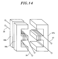
- Figs. 13 through 15 are perspective views showing the structures of cores 97a-99a, 97b-99b and 97c-99c wound with a power transmission coil 37 and power receiving coils 38 and 39 in a power supply system in accordance with a third embodiment of the present invention.
- the cores 98a, 98b, 98c, 99a, 99b and 99c wound with the power receiving coils 38 and 39 are arranged on one side of the cores 97a, 97b and 97c wound with the power receiving coil 37.
- the secondary cores 98a and 99a are of an "E"-like shape as with the secondary cores 48b and 49b illustrated in Fig. 5.
- the primary core 97a is of a structure in which two "E"-like cores are connected to each other in a longitudinal direction in such a fashion that the primary core 97a can face the secondary cores 98a and 99a arranged on one side thereof in a longitudinal (vertical) direction. For this reason, the power transmission coil 37 is divided into two coils 37a and 37b.
- the cross-sectional area of the facing portions of the primary core 97a is equal to or greater than the total cross-sectional area of the facing portions of secondary cores 98a and 99a.
- the secondary cores 98b and 99b are of an "E"-like shape as with the secondary cores 48b, 49b, 98a and 99a set forth above.
- the primary core 97b is of a structure in which two "E"-like cores are connected to each other in a thickness direction in such a fashion that the primary core 97b can face the secondary cores 98b and 99b arranged on one side thereof in a thickness (transverse) direction.
- the cross-sectional area of the facing portions of the primary core 97b is equal to or greater than the total cross-sectional area of the facing portions of secondary cores 98b and 99b.
- the secondary cores 98c and 99c are of a cylindrical shape or a rectangular column shape (cylindrical shape in Fig. 15) as with the secondary cores 48c and 49c illustrated in Fig. 6.
- the power transmission is performed by allowing the magnetic flux of the primary side to flow across the secondary coils 38 and 39.
- the primary core 97c is formed into a disk shape such that it can face the secondary cores 98c and 99c arranged on one side thereof side by side (in a transverse direction).
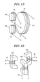
- Fig. 16 is a perspective view showing the structure of cores 107, 108 and 109 wound with a power transmission coil 37 and power receiving coils 38 and 39 in a power supply system in accordance with a fourth embodiment of the present invention.
- the respective coils 37, 38 and 39 are wound around the cores 107, 108 and 109 of a square bracket shape which in turn are arranged at an equal interval of 120 degrees when viewed from the top or bottom thereof. This configuration also ensures that the electric power is evenly transmitted from one power transmission coil 37 to two power receiving coils 38 and 39.
- the present invention is directed to a power supply system in which a voltage of the same frequency as that of the high frequency voltage applied to a high frequency power cable of a power supply device is applied to a power cable of a particular electric device.
- the voltage-current relationship has something to do with impedance.
- an electric current of the same frequency may flow through a power cable of a particular electric device, which also falls within the scope of the present invention.
- the present invention pertains to a system capable of performing a simultaneous parallel power feeding operation with respect to a plurality of particular electric devices, a high frequency alternating voltage is generated in the input port of the particular electric devices.
- An electronic switch, a mechanical switch, a converter circuit or the like, which serves to control energization, may be provided on a power cable or a circuit connected to the input port within particular electric devices, thereby making it possible to control a power feeding operation within the electric devices. It is a matter of course that this configuration is also within the scope of the present invention.
- Figs. 17A to 18B show configurations of a power supply system in accordance with a fifth embodiment of the present invention.
- This power supply system is for use in an electric shaver with a cleaning device and is similar to the systems shown in Figs. 1A to 3 and Figs. 10A and 10B. Corresponding parts will be designated by like reference numerals, with no description given in that regard.
- the power transmission coil 37 is wound around a primary core 107 for the electric shaver 32 and a metal contact 102 for power transmission to the cleaning device 103 or 103' is used together.
- the cleaning device 103 shown in Fig. 17B differs from the cleaning device 103' illustrated in Fig. 18B in terms of presence or absence of the induction heating coil 73.
- a power receiving metal contact 104 is provided on the cleaning device 103 or 103'.
- the metal contacts 102 and 104 are made of a material exhibiting high erosion resistance.
- a contactless power feeding operation may be performed with respect to the electric shaver 32 in which it is desirable not to expose any metal contact on a design surface, and a contacting type power feeding operation may be performed with respect to the cleaning device 103 or 103' in which power consumption is high and power loss needs to be avoided.
- the contacting type power feeding operation is cost-effective.
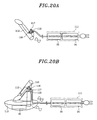
- Figs. 20A and 20B show configurations of a power supply system in accordance with a sixth embodiment of the present invention.
- This power supply system is for use in an electric shaver with a cleaning device and is similar to the system shown in Figs. 10A and 10B.
- Corresponding parts will be designated by like reference numerals, with no description given in that regard.
- the power receiving coils 118 and 119 serving as a secondary coil is configured to have no core. Accordingly, the power transmission coil 117 in the power feeding plug 116 of the power adapter 111 is inserted into the power receiving coils 118 and 119 wound in a ring shape.
Abstract
Description
- The present invention relates to a power supply system capable of feeding electric power from a single power adaptor to a plurality of load devices and, more specifically, to a power supply system in which a power feeding operation is performed by contactless power transmission based on electromagnetic induction.
- One example of power supply systems capable of feeding electric power from a single power adaptor to a plurality of load devices is an electric shaver with a cleaning device. Figs. 21A and 21B show configurations of a power supply system for use in the electric shaver. As shown in Fig. 21A, an
electric shaver 2 can be connected to apower adapter 1 which is formed of a RCC (ringing choke converter) and the like. As illustrated in Fig. 21B, acleaning device 3 can also be connected to thepower adapter 1. As depicted in Fig. 21B, it is possible not only to cleanse a blade of theelectric shaver 2 but also to electrically charge theelectric shaver 2 under the state that theelectric shaver 2 is mounted on thecleaning device 3. - In this case, since the
power adapter 1 is outputting a direct current of, e.g., 12V, the task of feeding electric power to a cleaningdevice driving circuit 4 in thecleaning device 3 and the task of charging theelectric shaver 2 mounted on thecleaning device 3 are performed through branch lines just in that condition. However, thepower adapter 1 needs to be connected to thecleaning device 3 or theelectric shaver 2 by way of a contactingtype contact point 5. Furthermore, due to the fact that thepower adapter 1 is feeding electric power of a voltage as high as 12V to match thecleaning device 3 of high power consumption, theelectric shaver 2 requires the use of a step-downpower converter 7 for dropping the voltage to a level suitable for charging asecondary battery 6. Thus, theelectric shaver 2 grows in size. - In the meantime, demand has existed for non-contact or contactless power feeding in an electric shaver which is frequently used in a water-abundant environment, e.g., in a lavatory. Fig. 22 illustrates a conventional power supply system by which power feeding is conducted in a contactless manner. A commercial alternating current inputted to a
power adapter 12 through apower cord 11 is converted to a direct current in aconverter 13. The direct current is converted to a high frequency alternating current in a voltage-resonant inverter 14 and then outputted from aprimary coil 15 which is an output port of thepower adapter 12. - The
primary coil 15 is magnetically coupled in a detachable manner to asecondary coil 17 which is an input port of anelectric shaver 16. The alternating voltage developed in thesecondary coil 17 is converted to a direct voltage in aconverter circuit 18 and then fed to aload 19 which is formed of a secondary battery and an electric motor. Theconverter circuit 18 is an A/D converter whose size is smaller than that of a DC-DC converter of the step-downpower converter 7 noted above. - Accordingly, the configurations depicted in Figs. 23A and 23B are provided if the contactless power supply system illustrated in Fig. 22 is applied to the power supply system shown in Figs. 21A and 21B, to which a plurality of load devices including the
cleaning device 3 is connectable. - A
power adapter 21, which is formed of a voltage-resonant inverter and so forth, serves to output an alternating current of, e.g., 50kHz and 30V, to apower transmission coil 24. Apower receiving coil 25 of anelectric shaver 22 can be connected in a contactless manner to thepower transmission coil 24 as shown in Fig. 23A. Likewise, apower receiving coil 26 of acleaning device 23 can be connected in a contactless manner to thepower transmission coil 24 as shown in Fig. 23B. - As can be seen in Fig. 23B, an A/
D converter 27 is provided in thecleaning device 23. The A/D converter 27 is adapted to generate, e.g., a direct current of 12V, and feed the same to a cleaningdevice driving circuit 28. In order to charge theelectric shaver 22 kept mounted on thecleaning device 23, aninverter 29 formed of a voltage-resonant inverter and the like for outputting an alternating current of, e.g., 50kHz and 30V, and apower transmission coil 30 are provided in thecleaning device 23. - In this regard, one example of parallel power feeding techniques using electromagnetic induction is disclosed in, e.g.,
Japanese Laid-open Application H3-101110A - In the configurations shown in Fig. 23A and 23B, the
converter 27 and theinverter 29 need to be additionally provided in thecleaning device 23 for the purpose of realizing a contactless power feeding operation. This leads to an increase in size and costs. - In view of the foregoing and other problems, it is an object of the present invention to provide a power supply system that can feed electric power from a single power adaptor to a plurality of load devices in a contactless manner, while simplifying the configuration of the load devices.
- In accordance with the present invention, there is provided a power supply system for feeding electric power from a power adapter to a plurality of load devices, wherein the power adapter includes a primary core; and a primary coil wound around the primary core for serving as a output port of the power adapter to output an alternating current, and wherein the load devices include secondary cores for simultaneously forming magnetic circuits between the primary core and the load devices; and secondary coils wound around the secondary cores for feeding output power to the load devices.
- According to the configuration recited above, it is possible to feed electric power from a single power adapter to a plurality of load devices separately or simultaneously. To this end, a high frequency alternating current is used as an output power, and the primary core and the primary coil wound around the primary core are used as an output port. In the meantime, the load devices are provided with secondary cores capable of forming magnetic circuits with the primary core and secondary coils wound around the secondary cores. This makes it possible to generate output power to be fed. Thus, it is possible to obtain a desired output voltage by adjusting a coil winding ratio or magnetic flux interlinkage of the coils. In this way, electric power can be fed from a single power adapter to a plurality of load devices in a contactless manner. In the present invention, the cores are formed into such a shape as to simultaneously form magnetic circuits on a load device basis, thereby making it possible to perform a parallel power feeding operation.
- Accordingly, in the course of feeding electric power to a plurality of load devices in a contactless fashion, the input ports of the plurality of load devices can be connected to the output port of the single power adapter to thereby perform a parallel power feeding operation. This eliminates the need to provide a power conversion unit, such as a converter or an inverter, which would otherwise be required in transmitting electric power from one load device to another. Thus, the configuration of the power supply system can be simplified.
- Preferably, the primary core has two pairs of protrusions, each of the pairs of the protrusions extending in a same direction, and one of the pairs of the protrusions oriented in an opposite direction with respect to the other of the pairs of the protrusions, and he secondary cores, each of which has a pair of protrusions extending in a same direction, are arranged on opposite sides of the primary core in such a manner that the primary core lies between the secondary cores to feed electric power simultaneously to the load devices.
- According to the configuration recited above, electric power can be fed to two load devices with a simple structure by adopting a three-stage stack structure in which the secondary cores are arranged on opposite sides of the primary core in such a manner that the primary core lie between the secondary cores.
- Preferably, the primary core has two pairs of protrusions and a shaft portion wound with the primary coil, each of the pairs of protrusions extending in a same direction from the shaft portion, and one of the pairs of protrusions oriented in an orthogonal direction with respect to the other of the pairs of protrusions. Further, each of the secondary cores has two pairs of protrusions, each of the pairs of protrusions extending in a same direction, and the secondary cores arranged in such a manner that the secondary cores form an "L"-shape with the primary core when viewed from an axial direction of the shaft portion to feed electric power simultaneously to the load devices.
- According to the configuration recited above, two secondary cores are arranged so as to form an "L"-like shape with a primary core. Thus, in case where one load device is slantingly mounted on the other load device, the primary core can be placed in close proximity with the secondary cores received in the respective load devices.
- Preferably, the primary core is formed in a bobbin shape and the secondary cores are formed in a square bracket shape, the secondary cores arranged in plural numbers around the primary core in such a manner that opposite ends of the secondary cores face flanges of the primary core to feed electric power simultaneously to the load devices.
- According to the configuration recited above, the flanges of a bobbin are allowed to serve as protrusions extending from the primary core toward the secondary cores. Thus, magnetic paths can be formed by merely arranging the secondary cores around the primary core. This means that the secondary cores can be arranged in the number decided by the diameter or the like of the secondary coils wound around the center portion of the square-bracket-shaped secondary cores.
- Therefore, it is possible to simultaneously feed electric power to a large number of load devices with a simplified structure.
- Preferably, an electric shaver serves as a first load device of the load devices, and a cleaning device used for the electric shaver serves as a second load device of the load devices. Further, the electric shaver is to be fed with the electric power directly from the power adapter and to be electrically charged in a state that the electric shaver is mounted on the cleaning device.
- According to the configuration recited above, use is made of the three-stage stack structure or the "L"-like structure that allows the primary core to be simply inserted between the cleaning device and the electric shaver mounted on the cleaning device. Thus, it is desirable for the electric shaver system to employ the three-stage stack structure or the "L"-like structure.
- As set forth above, the power supply system of the present invention makes it possible to feed electric power from a single power adapter to a plurality of load devices separately or simultaneously. To this end, a high frequency alternating current is used as an output power, and the primary core and the primary coil wound around the primary core are used as an output port. In the meantime, the load devices are provided with secondary cores capable of forming magnetic circuits with the primary core and secondary coils wound around the secondary cores. This makes it possible to generate output power to be fed. In the present invention, the cores are formed into such a shape as to simultaneously form magnetic circuits on a load device basis, thereby making it possible to perform a parallel power feeding operation.
- Accordingly, in the course of feeding electric power to a plurality of load devices in a contactless fashion, the input ports of the plurality of load devices can be connected to the output port of the single power adapter to thereby perform a parallel power feeding operation. This eliminates the need to provide a power conversion unit, such as a converter or an inverter, which would otherwise be required in transmitting electric power from one load device to another. Thus, the configuration of the power supply system can be simplified.
- Figs. 1A and 1B show configurations of a power supply system in accordance with a first embodiment of the present invention;
- Figs. 2A and 2B show other configurations of a power supply system in accordance with the first embodiment of the present invention;
- Fig. 3 is a block diagram illustrating an electric configuration of the power supply system shown in Figs. 1A and 1B;
- Fig. 4 is a perspective view showing a structure of individual coils wound around cores to perform a contactless power feeding operation in the power supply system shown in Fig. 1 or Fig. 2;
- Fig. 5 is a perspective view showing another structure of individual coils wound around cores to perform a contactless power feeding operation in the power supply system shown in Fig. 1 or Fig. 2;
- Fig. 6 is a perspective view showing a further structure of individual coils wound around cores to perform a contactless power feeding operation in the power supply system shown in Fig. 1 or Fig. 2;
- Fig. 7 is a perspective view showing a still further structure of individual coils wound around cores to perform a contactless power feeding operation in the power supply system shown in Fig. 1 or Fig. 2;
- Fig. 8 is a cross sectional view of the structure of individual coils wound around cores shown in Fig. 7;
- Fig. 9 is a perspective view showing an yet still further structure of individual coils wound around cores to perform a contactless power feeding operation in the power supply system shown in Fig. 1 or Fig. 2;
- Figs. 10A and 10B show configurations of a power supply system in accordance with a second embodiment of the present invention;
- Fig. 11 is a perspective view showing a structure of individual coils wound around cores to perform a contactless power feeding operation in the power supply system shown in Figs. 10A and 10B;
- Fig. 12 is a perspective view showing another structure of individual coils wound around cores to perform a contactless power feeding operation in the power supply system shown in Fig. 10;
- Fig. 13 is a perspective view showing a structure of cores wound with power transmission coils and power receiving coils in a power supply system in accordance with a third embodiment of the present invention;
- Fig. 14 is a perspective view showing a structure of cores wound with a power transmission coil and power receiving coils in the power supply system in accordance with the third embodiment of the present invention;
- Fig. 15 is a perspective view showing a structure of cores wound with a power transmission coil and power receiving coils in the power supply system in accordance with the third embodiment of the present invention;
- Fig. 16 is a perspective view showing a structure of cores wound with a power transmission coil and power receiving coils in a power supply system in accordance with a fourth embodiment of the present invention;
- Figs. 17A and 17B show configurations of a power supply system in accordance with a fifth embodiment of the present invention;
- Figs. 18A and 18B show other configurations of a power supply system in accordance with the fifth embodiment of the present invention;
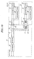
- Fig. 19 is a block diagram illustrating an electric configuration of the power supply system shown in Figs. 17A and 17B;
- Figs. 20A and 20B show configurations of a power supply system in accordance with a sixth embodiment of the present invention;
- Figs. 21A and 21B show configurations of a conventional contacting type power supply system;
- Fig. 22 shows a configuration of a conventional non-contacting type power supply system; and
- Figs. 23A and 23B show configurations in which the non-contacting type power supply system shown in Fig. 22 is applied to the contacting type power supply system shown in Figs. 21A and 21B.
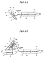
- Figs. 1A to 2B show configurations of a power supply system in accordance with a first embodiment of the present invention. The power supply system is for use in an electric shaver with a cleaning device. As shown in Figs. 1A and 2A, an
electric shaver 32 can be connected to asingle power adapter cleaning device 33 can also be connected to thepower adapter electric shaver 32 but also to electrically charge theelectric shaver 32 under the state that theelectric shaver 32 is mounted on thecleaning device 33. - The
power adapter converter 34, which is formed of a diode bridge, a smoothing capacitor and the like, and a voltage-resonant inverter 35. Thepower adapter power transmission coil 37 of a single power feeding plug 36 that serves as an output port and constitutes a primary coil of a transformer. Apower receiving coil 38 of theelectric shaver 32 that serves as an input port and constitutes a secondary coil of the transformer can be connected to thepower transmission coil 37 in a contactless manner as illustrated in Figs. 1A, 1B, 2A and 2B. Apower receiving coil 39 of thecleaning device 33 can also be connected to thepower transmission coil 37 in a contactless manner as illustrated in Figs. 1B and 2B. - The
converter 34 and the voltage-resonant inverter 35 are configured integrally in thepower adapter 31 shown in Figs. 1A and 1B . This configuration is suitable for a case where apower cable 40 extends relatively short between thepower adapter 31 and theelectric shaver 32 or thecleaning device 33. A high frequency current flows through thepower cable 40. If an inverter of a power supply device is of a resonance type, it generates a sinusoidal or trapezoidal voltage waveform with a reduced noise component. This makes it possible to reduce the radiation noise generated in a power cable which extends a long distance and the radiation noise caused by a magnetic field which is leaked in a small amount from a coil part for electromagnetic induction coupling. Accordingly, it is possible to get rid of an anti-noise part. - The
converter 34 and the voltage-resonant inverter 35 are configured separately in thepower adapter 31a shown in Figs. 2A and 2B. This configuration helps to avoid radiation of a high frequency wave and is suitable for a case where apower cable 40a extends relatively long. A direct current of, e.g., 12V, is adapted to flow through thepower cable 40a. - Provided in the
electric shaver 32 are aload circuit 41 formed of a secondary battery, an electric motor and the like, and a step-downpower converter 42 formed of an A/D converter and adapted to generate a direct current of, e.g., 3V, suitable for use in theload circuit 41, by use of the alternating current generated in thepower receiving coil 38. Furthermore, a cleaningdevice driving circuit 43 biased with the alternating current generated in thepower receiving coil 39 is provided in thecleaning device 33. - Fig. 3 is a block diagram illustrating an electric configuration of the power supply system shown in Figs. 1A and 1B. Parts corresponding to those of the configuration shown in Figs. 1A and 1B will be designated by like reference numerals, with no description given in that respect. In the
power adapter 31, thepower transmission coil 37 serving as a primary coil is wound around aprimary core 47 made of a magnetic material. In theelectric shaver 32, thepower receiving coil 38 serving as a secondary coil is wound around asecondary core 48 made of a magnetic material. Similarly, in thecleaning device 33, thepower receiving coil 39 serving as a secondary coil is wound around asecondary core 49 made of a magnetic material. In this way, thesecondary cores primary core 47 in parallel through magnetic flux, thereby performing the contactless power transmission based on electromagnetic induction. - The
electric shaver 32 includes aconverter 51 serving as the step-downpower converter 42, aload circuit 52, such as an electric motor and the like, connected to theconverter 51, aconverter 53 arranged in parallel with theconverter 51, and aload circuit 54, such as a microcomputer and the like, driven by theconverter 53. Thecleaning device 33 includes aconverter 55, aload circuit 56, such as a cleaning water pumping motor, a drying fan, a drying-purpose induction heating circuit and the like, connected to theconverter 55, aconverter 57 arranged in parallel with theconverter 55, and aload circuit 58, such as a microcomputer and the like, driven by theconverter 57. - Attention is drawn to the fact that, in the present invention, the
power transmission coil 37 of thepower adapter electric shaver 32 is mounted on thecleaning device 33, as illustrated in Figs. 1B and 2B. Taking this into account, thecleaning device 33 is provided with aslot 59a for reception of thepower feeding plug 36 of a plate shape. Thepower receiving coil 38 in thecleaning device 33 is attached to the back side of theslot 59a within anonmagnetic casing 59b. In theelectric shaver 32, thepower receiving coil 38 is arranged within anonmagnetic casing 59c so that it can face thepower feeding plug 36 when theelectric shaver 32 is mounted on thecleaning device 33. - Figs. 4 through 9 show the structures of the
individual coils cores primary core 47a forms magnetic circuits with a plurality of independently arrangedsecondary cores primary core 47a is formed into an "I"-like shape and has two pairs ofprotrusions secondary cores protrusions respective protrusions primary core 47a are arranged to face the correspondingprotrusions secondary cores protrusions protrusions - As a consequence, there is provided a three-stage stack structure wherein the
secondary cores primary core 47a serving as an output port core. As illustrated in Figs. 1B and 2B, thepower feeding plug 36 is inserted between the cleaningdevice 33 and theelectric shaver 32. By doing so, it is possible to perform a simultaneous power feeding operation for two load devices with a simplified and compact structure. - In the structure shown in Fig. 5,
secondary cores protrusions primary core 47b is shaped to have a plurality ofprotrusions protrusions secondary cores primary coil 37 is divided into twocoils - This configuration also ensures that a high magnetic coupling ratio is achieved between the
primary core 47b serving as an output port core and thesecondary cores - In the structure shown in Fig. 6,
cores cores cores primary core 47c serving as an output port core and thesecondary cores - The structure illustrated in Figs. 7 and 8 is similar to the structures shown in Figs. 5 and 6. Two
secondary cores tubular body 67, anend plate 68 closing off one end portion of thetubular body 67 and aconcentric post 69 erected from the center of theend plate 68.Coils posts 69 of thesecondary cores secondary cores primary core 47d is of a shape looking as if thesecondary cores primary core 47d is provided with twoposts 69 wound withcoils 37. Thus, thetubular bodies 67 and theposts 69 of thesecondary cores primary core 47d, forming magnetic circuits closed off by theend plates 68. Leakage of magnetic flux is kept small because theposts 69 wound with thecoils tubular bodies 67. - This configuration also ensures that a high magnetic coupling ratio is achieved between the
primary core 47d serving as an output port core and thesecondary cores - In the structure shown in Fig. 9, a
primary core 47e is of an elongated cylindrical shape or an elongated rectangular column shape (cylindrical shape in Fig. 9). Twosecondary cores primary core 47e to pass through the centers of thesecondary cores Secondary coils cores - This configuration also ensures that a high magnetic coupling ratio is achieved between the
primary core 47e serving as an output port core and thesecondary cores primary core 47e need to be formed on thecasings - Use of the structures of cores and coils illustrated in Figs. 4 through 9 makes it possible to perform a contactless parallel power feeding operation by means of a simple and compact three-stage stack structure in which the
power transmission coil 37 lies in proximity with both of the power receiving coils 38 and 39. This eliminates the need to provide a power conversion unit such as a converter, an inverter or the like in thecleaning device 33, which would otherwise be required in feeding electric power to theelectric shaver 32 under the state that theelectric shaver 32 is mounted on thecleaning device 33. - Figs. 10A and 10B show configurations of a power supply system in accordance with a second embodiment of the present invention. The power supply system is for use in an electric shaver with a cleaning device and is similar to the system shown in Figs. 1A to 2B. Corresponding parts will be designated by like reference numerals, with no description given in that regard. Attention is invited to the fact that, in the system of this embodiment, a power feeding plug 76 of a
power adapter 71 is formed into a wedge shape, as illustrated in Fig. 10B, in order to cope with the inclined mounting of theelectric shaver 32 on thecleaning device 73. As in thepower adapter 31a illustrated in Figs. 2A and 2B, theconverter 34 and the voltage-resonant inverter 35 may be separated from each other, with a direct current being transmitted through thepower cable 40a. - An
induction heating coil 74 for drying a blade of theelectric shaver 32 by induction heating is connected to thecleaning device 73 in parallel with the cleaningdevice driving circuit 43. Theinduction heating coil 74 is activated by a switch not shown in the drawings and controlled by the cleaningdevice driving circuit 43 to thereby induction-heat and dry the blade of theelectric shaver 32 with a high frequency alternating current of 50kHz at the end of a cleaning process. - Fig. 11 is a perspective view showing a structure of
cores power transmission coil 77 of thepower feeding plug 76 and the power receiving coils 38 and 39. In the structure shown in Fig. 11, aprimary core 87a forms magnetic circuits with two independently arrangedsecondary cores primary core 87a has two pairs ofprotrusions protrusions shaft portion 85 wound with thepower transmission coil 77. In a corresponding fashion, each of thesecondary cores protrusions terminal cores respective protrusions primary core 87a are arranged to face the correspondingprotrusions secondary cores protrusions protrusions - As a consequence, there is provided an "L"-like structure wherein the
primary core 47a serving as an output port core is sandwichedly placed between thesecondary cores electric shaver 32 is slantingly mounted on thecleaning device 73 as illustrated in Fig. 10B, theprimary core 87a can be in close proximity with thesecondary cores electric shaver 32 and thecleaning device 73. - Fig. 12 is a perspective view showing a structure of
cores power transmission coil 77 of thepower feeding plug 76 and the power receiving coils 38 and 39. In the structure shown in Fig. 12, twosecondary cores cores primary core 87b is formed into a bobbin shape. Thesecondary cores primary core 87b in such a manner that theprotrusions secondary cores flanges 87c of theprimary core 87b. This makes it possible to simultaneously feed electric power to the corresponding load devices. - If the flanges of a bobbin is allowed to serve as protrusions extending from the
primary core 87b toward thesecondary cores secondary cores primary core 87b. This means that the secondary cores can be arranged in the number decided by the diameter or the like of the power receiving coils 38 and 39 wound around the center portion of the square-bracket-shaped secondary cores. Three secondary cores including the one designated byreference numeral 90b are arranged in the embodiment shown in Fig. 12. - Use of the structures of cores and coils illustrated in Figs. 11 and 12 makes it possible to feed electric power to two slantingly mounted load devices in a contactless and parallel manner with a simple and compact "L"-like structure in which the power receiving coils 38 and 39 are disposed on the opposite sides of the
power transmission coil 77. - Figs. 13 through 15 are perspective views showing the structures of
cores 97a-99a, 97b-99b and 97c-99c wound with apower transmission coil 37 and power receiving coils 38 and 39 in a power supply system in accordance with a third embodiment of the present invention. In respect of therespective cores 97a-99a, 97b-99b and 97c-99c, it is to be noted that thecores cores power receiving coil 37. - In the
cores secondary cores secondary cores primary core 97a is of a structure in which two "E"-like cores are connected to each other in a longitudinal direction in such a fashion that theprimary core 97a can face thesecondary cores power transmission coil 37 is divided into twocoils primary core 97a is equal to or greater than the total cross-sectional area of the facing portions ofsecondary cores - In the
cores secondary cores secondary cores primary core 97b is of a structure in which two "E"-like cores are connected to each other in a thickness direction in such a fashion that theprimary core 97b can face thesecondary cores primary core 97b is equal to or greater than the total cross-sectional area of the facing portions ofsecondary cores - In the
cores secondary cores secondary cores secondary coils primary core 97c is formed into a disk shape such that it can face thesecondary cores - Use of the structures shown in Figs. 13 through 15 ensures that the power transmission is properly performed for two juxtaposed load devices.
- Fig. 16 is a perspective view showing the structure of
cores power transmission coil 37 and power receiving coils 38 and 39 in a power supply system in accordance with a fourth embodiment of the present invention. It is to be noted that, in this embodiment, therespective coils cores power transmission coil 37 to two power receiving coils 38 and 39. - The present invention is directed to a power supply system in which a voltage of the same frequency as that of the high frequency voltage applied to a high frequency power cable of a power supply device is applied to a power cable of a particular electric device. However, the voltage-current relationship has something to do with impedance. Thus, in case where the output power of an inverter of a power supply device equivalently constitutes a high frequency current source, an electric current of the same frequency may flow through a power cable of a particular electric device, which also falls within the scope of the present invention. Seeing that the present invention pertains to a system capable of performing a simultaneous parallel power feeding operation with respect to a plurality of particular electric devices, a high frequency alternating voltage is generated in the input port of the particular electric devices. An electronic switch, a mechanical switch, a converter circuit or the like, which serves to control energization, may be provided on a power cable or a circuit connected to the input port within particular electric devices, thereby making it possible to control a power feeding operation within the electric devices. It is a matter of course that this configuration is also within the scope of the present invention.
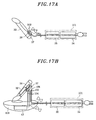
- Figs. 17A to 18B show configurations of a power supply system in accordance with a fifth embodiment of the present invention. This power supply system is for use in an electric shaver with a cleaning device and is similar to the systems shown in Figs. 1A to 3 and Figs. 10A and 10B. Corresponding parts will be designated by like reference numerals, with no description given in that regard. As shown in Fig. 19, in the
power feeding plug 106 of apower adapter 101 of this embodiment, thepower transmission coil 37 is wound around aprimary core 107 for theelectric shaver 32 and ametal contact 102 for power transmission to thecleaning device 103 or 103' is used together. Thecleaning device 103 shown in Fig. 17B differs from the cleaning device 103' illustrated in Fig. 18B in terms of presence or absence of theinduction heating coil 73. - In a corresponding manner, a power receiving
metal contact 104 is provided on thecleaning device 103 or 103'. Themetal contacts power cable 40 for an alternating current of 50kHz, a contactless power feeding operation may be performed with respect to theelectric shaver 32 in which it is desirable not to expose any metal contact on a design surface, and a contacting type power feeding operation may be performed with respect to thecleaning device 103 or 103' in which power consumption is high and power loss needs to be avoided. The contacting type power feeding operation is cost-effective. - Figs. 20A and 20B show configurations of a power supply system in accordance with a sixth embodiment of the present invention. This power supply system is for use in an electric shaver with a cleaning device and is similar to the system shown in Figs. 10A and 10B. Corresponding parts will be designated by like reference numerals, with no description given in that regard. In an
electric shaver 112 and acleaning device 113 of this embodiment, the power receiving coils 118 and 119 serving as a secondary coil is configured to have no core. Accordingly, thepower transmission coil 117 in thepower feeding plug 116 of thepower adapter 111 is inserted into the power receiving coils 118 and 119 wound in a ring shape. - While the invention has been shown and described with respect to the preferred embodiments, it will be understood by those skilled in the art that various changes and modification may be made without departing from the scope of the invention as defined in the following claims.
Claims (6)
- A power supply system for feeding electric power from a power adapter to a plurality of load devices,
wherein the power adapter includes:a primary core; anda primary coil wound around the primary core for serving as a output port of the power adapter to output an alternating current, andwherein the load devices include:secondary cores for simultaneously forming magnetic circuits between the primary core and the load devices; andsecondary coils wound around the secondary cores for feeding output power to the load devices. - The power supply system of claim 1, wherein the primary core has two pairs of protrusions, each of the pairs of the protrusions extending in a same direction, and one of the pairs of the protrusions oriented in an opposite direction with respect to the other of the pairs of the protrusions, and
wherein the secondary cores, each of which has a pair of protrusions extending in a same direction, are arranged on opposite sides of the primary core in such a manner that the primary core lies between the secondary cores to feed electric power simultaneously to the load devices. - The power supply system of claim 1, wherein the primary core has two pairs of protrusions and a shaft portion wound with the primary coil, each of the pairs of protrusions extending in a same direction from the shaft portion, and one of the pairs of protrusions oriented in an orthogonal direction with respect to the other of the pairs of protrusions, and
wherein each of the secondary cores has two pairs of protrusions, each of the pairs of protrusions extending in a same direction, and the secondary cores arranged in such a manner that the secondary cores form an "L"-shape with the primary core when viewed from an axial direction of the shaft portion to feed electric power simultaneously to the load devices. - The power supply system of claim 1, wherein the primary core is formed in a bobbin shape and the secondary cores are formed in a square bracket shape, the secondary cores arranged in plural numbers around the primary core in such a manner that opposite ends of the secondary cores face flanges of the primary core to feed electric power simultaneously to the load devices.
- The power supply system of claim 2, wherein an electric shaver serves as a first load device of the load devices, and a cleaning device used for the electric shaver serves as a second load device of the load devices, and
wherein the electric shaver is to be fed with the electric power directly from the power adapter and to be electrically charged in a state that the electric shaver is mounted on the cleaning device. - The power supply system of claim 3, wherein an electric shaver serves as a first load device of the load devices, and a cleaning device used for the electric shaver serves as a second load device of the load devices, and
wherein the electric shaver is to be fed with the electric power directly from the power adapter and to be electrically charged in a state that the electric shaver is mounted on the cleaning device.
Applications Claiming Priority (1)
| Application Number | Priority Date | Filing Date | Title |
|---|---|---|---|
| JP2005311087A JP4852970B2 (en) | 2005-10-26 | 2005-10-26 | Power supply system |
Publications (2)
| Publication Number | Publication Date |
|---|---|
| EP1780862A2 true EP1780862A2 (en) | 2007-05-02 |
| EP1780862A3 EP1780862A3 (en) | 2009-04-01 |
Family
ID=37680578
Family Applications (1)
| Application Number | Title | Priority Date | Filing Date |
|---|---|---|---|
| EP06022179A Withdrawn EP1780862A3 (en) | 2005-10-26 | 2006-10-23 | Power supply system |
Country Status (4)
| Country | Link |
|---|---|
| US (1) | US7514818B2 (en) |
| EP (1) | EP1780862A3 (en) |
| JP (1) | JP4852970B2 (en) |
| CN (2) | CN201001086Y (en) |
Cited By (3)
| Publication number | Priority date | Publication date | Assignee | Title |
|---|---|---|---|---|
| EP2393181A1 (en) * | 2010-06-02 | 2011-12-07 | FRIWO Gerätebau GmbH | Circuit for a system for a contactless, inductive energy transfer |
| EP2528194A4 (en) * | 2010-01-21 | 2017-08-30 | Sharp Kabushiki Kaisha | Contactless electricity-supplying device |
| CN110308322A (en) * | 2019-06-29 | 2019-10-08 | 杭州涂鸦信息技术有限公司 | A method of calculating power supply adaptor electricity |
Families Citing this family (112)
| Publication number | Priority date | Publication date | Assignee | Title |
|---|---|---|---|---|
| EP2306615B1 (en) * | 2005-07-12 | 2020-05-27 | Massachusetts Institute of Technology (MIT) | Wireless non-radiative energy transfer |
| US7825543B2 (en) | 2005-07-12 | 2010-11-02 | Massachusetts Institute Of Technology | Wireless energy transfer |
| US8805530B2 (en) | 2007-06-01 | 2014-08-12 | Witricity Corporation | Power generation for implantable devices |
| US9421388B2 (en) | 2007-06-01 | 2016-08-23 | Witricity Corporation | Power generation for implantable devices |
| WO2009070195A1 (en) * | 2007-11-27 | 2009-06-04 | Extremely Ingenious Engineering, Llc | Methods and systems for wireless energy and data transmission |
| EP2281322B1 (en) * | 2008-05-14 | 2016-03-23 | Massachusetts Institute of Technology | Wireless energy transfer, including interference enhancement |
| US9577436B2 (en) | 2008-09-27 | 2017-02-21 | Witricity Corporation | Wireless energy transfer for implantable devices |
| US8461722B2 (en) | 2008-09-27 | 2013-06-11 | Witricity Corporation | Wireless energy transfer using conducting surfaces to shape field and improve K |
| US8928276B2 (en) | 2008-09-27 | 2015-01-06 | Witricity Corporation | Integrated repeaters for cell phone applications |
| US8466583B2 (en) | 2008-09-27 | 2013-06-18 | Witricity Corporation | Tunable wireless energy transfer for outdoor lighting applications |
| US9035499B2 (en) | 2008-09-27 | 2015-05-19 | Witricity Corporation | Wireless energy transfer for photovoltaic panels |
| US9106203B2 (en) | 2008-09-27 | 2015-08-11 | Witricity Corporation | Secure wireless energy transfer in medical applications |
| US9396867B2 (en) | 2008-09-27 | 2016-07-19 | Witricity Corporation | Integrated resonator-shield structures |
| US8772973B2 (en) | 2008-09-27 | 2014-07-08 | Witricity Corporation | Integrated resonator-shield structures |
| US8947186B2 (en) | 2008-09-27 | 2015-02-03 | Witricity Corporation | Wireless energy transfer resonator thermal management |
| US8400017B2 (en) | 2008-09-27 | 2013-03-19 | Witricity Corporation | Wireless energy transfer for computer peripheral applications |
| US8569914B2 (en) | 2008-09-27 | 2013-10-29 | Witricity Corporation | Wireless energy transfer using object positioning for improved k |
| US8922066B2 (en) | 2008-09-27 | 2014-12-30 | Witricity Corporation | Wireless energy transfer with multi resonator arrays for vehicle applications |
| US9544683B2 (en) | 2008-09-27 | 2017-01-10 | Witricity Corporation | Wirelessly powered audio devices |
| US9744858B2 (en) | 2008-09-27 | 2017-08-29 | Witricity Corporation | System for wireless energy distribution in a vehicle |
| US9093853B2 (en) | 2008-09-27 | 2015-07-28 | Witricity Corporation | Flexible resonator attachment |
| US8643326B2 (en) | 2008-09-27 | 2014-02-04 | Witricity Corporation | Tunable wireless energy transfer systems |
| US8304935B2 (en) | 2008-09-27 | 2012-11-06 | Witricity Corporation | Wireless energy transfer using field shaping to reduce loss |
| US9160203B2 (en) | 2008-09-27 | 2015-10-13 | Witricity Corporation | Wireless powered television |
| US9065423B2 (en) | 2008-09-27 | 2015-06-23 | Witricity Corporation | Wireless energy distribution system |
| US9318922B2 (en) | 2008-09-27 | 2016-04-19 | Witricity Corporation | Mechanically removable wireless power vehicle seat assembly |
| US8410636B2 (en) | 2008-09-27 | 2013-04-02 | Witricity Corporation | Low AC resistance conductor designs |
| US8482158B2 (en) | 2008-09-27 | 2013-07-09 | Witricity Corporation | Wireless energy transfer using variable size resonators and system monitoring |
| US8461720B2 (en) | 2008-09-27 | 2013-06-11 | Witricity Corporation | Wireless energy transfer using conducting surfaces to shape fields and reduce loss |
| US9105959B2 (en) | 2008-09-27 | 2015-08-11 | Witricity Corporation | Resonator enclosure |
| US8907531B2 (en) | 2008-09-27 | 2014-12-09 | Witricity Corporation | Wireless energy transfer with variable size resonators for medical applications |
| US8461721B2 (en) * | 2008-09-27 | 2013-06-11 | Witricity Corporation | Wireless energy transfer using object positioning for low loss |
| US8933594B2 (en) | 2008-09-27 | 2015-01-13 | Witricity Corporation | Wireless energy transfer for vehicles |
| US9246336B2 (en) | 2008-09-27 | 2016-01-26 | Witricity Corporation | Resonator optimizations for wireless energy transfer |
| US8497601B2 (en) | 2008-09-27 | 2013-07-30 | Witricity Corporation | Wireless energy transfer converters |
| US8441154B2 (en) | 2008-09-27 | 2013-05-14 | Witricity Corporation | Multi-resonator wireless energy transfer for exterior lighting |
| US9515494B2 (en) | 2008-09-27 | 2016-12-06 | Witricity Corporation | Wireless power system including impedance matching network |
| US9184595B2 (en) | 2008-09-27 | 2015-11-10 | Witricity Corporation | Wireless energy transfer in lossy environments |
| US9601261B2 (en) | 2008-09-27 | 2017-03-21 | Witricity Corporation | Wireless energy transfer using repeater resonators |
| US8901779B2 (en) | 2008-09-27 | 2014-12-02 | Witricity Corporation | Wireless energy transfer with resonator arrays for medical applications |
| US8471410B2 (en) | 2008-09-27 | 2013-06-25 | Witricity Corporation | Wireless energy transfer over distance using field shaping to improve the coupling factor |
| US8901778B2 (en) | 2008-09-27 | 2014-12-02 | Witricity Corporation | Wireless energy transfer with variable size resonators for implanted medical devices |
| US8692410B2 (en) | 2008-09-27 | 2014-04-08 | Witricity Corporation | Wireless energy transfer with frequency hopping |
| US8629578B2 (en) | 2008-09-27 | 2014-01-14 | Witricity Corporation | Wireless energy transfer systems |
| US8686598B2 (en) | 2008-09-27 | 2014-04-01 | Witricity Corporation | Wireless energy transfer for supplying power and heat to a device |
| US8946938B2 (en) | 2008-09-27 | 2015-02-03 | Witricity Corporation | Safety systems for wireless energy transfer in vehicle applications |
| US9601270B2 (en) | 2008-09-27 | 2017-03-21 | Witricity Corporation | Low AC resistance conductor designs |
| EP3544196B1 (en) | 2008-09-27 | 2023-09-13 | WiTricity Corporation | Wireless energy transfer systems |
| US8957549B2 (en) | 2008-09-27 | 2015-02-17 | Witricity Corporation | Tunable wireless energy transfer for in-vehicle applications |
| US8692412B2 (en) | 2008-09-27 | 2014-04-08 | Witricity Corporation | Temperature compensation in a wireless transfer system |
| US8587153B2 (en) | 2008-09-27 | 2013-11-19 | Witricity Corporation | Wireless energy transfer using high Q resonators for lighting applications |
| US8552592B2 (en) | 2008-09-27 | 2013-10-08 | Witricity Corporation | Wireless energy transfer with feedback control for lighting applications |
| US9601266B2 (en) | 2008-09-27 | 2017-03-21 | Witricity Corporation | Multiple connected resonators with a single electronic circuit |
| US8587155B2 (en) | 2008-09-27 | 2013-11-19 | Witricity Corporation | Wireless energy transfer using repeater resonators |
| US8598743B2 (en) | 2008-09-27 | 2013-12-03 | Witricity Corporation | Resonator arrays for wireless energy transfer |
| US8476788B2 (en) | 2008-09-27 | 2013-07-02 | Witricity Corporation | Wireless energy transfer with high-Q resonators using field shaping to improve K |
| US8487480B1 (en) * | 2008-09-27 | 2013-07-16 | Witricity Corporation | Wireless energy transfer resonator kit |
| US8963488B2 (en) | 2008-09-27 | 2015-02-24 | Witricity Corporation | Position insensitive wireless charging |
| US8937408B2 (en) | 2008-09-27 | 2015-01-20 | Witricity Corporation | Wireless energy transfer for medical applications |
| US8723366B2 (en) | 2008-09-27 | 2014-05-13 | Witricity Corporation | Wireless energy transfer resonator enclosures |
| US8324759B2 (en) | 2008-09-27 | 2012-12-04 | Witricity Corporation | Wireless energy transfer using magnetic materials to shape field and reduce loss |
| US8912687B2 (en) | 2008-09-27 | 2014-12-16 | Witricity Corporation | Secure wireless energy transfer for vehicle applications |
| US8669676B2 (en) | 2008-09-27 | 2014-03-11 | Witricity Corporation | Wireless energy transfer across variable distances using field shaping with magnetic materials to improve the coupling factor |
| EP2345100B1 (en) | 2008-10-01 | 2018-12-05 | Massachusetts Institute of Technology | Efficient near-field wireless energy transfer using adiabatic system variations |
| JP5393804B2 (en) | 2008-12-12 | 2014-01-22 | チュンキル ジョン | Non-contact power charging station having a planar spiral core structure, non-contact power receiver, and control method thereof |
| US9602168B2 (en) | 2010-08-31 | 2017-03-21 | Witricity Corporation | Communication in wireless energy transfer systems |
| US9948145B2 (en) | 2011-07-08 | 2018-04-17 | Witricity Corporation | Wireless power transfer for a seat-vest-helmet system |
| CA2844062C (en) | 2011-08-04 | 2017-03-28 | Witricity Corporation | Tunable wireless power architectures |
| EP2998153B1 (en) | 2011-09-09 | 2023-11-01 | WiTricity Corporation | Foreign object detection in wireless energy transfer systems |
| US20130062966A1 (en) | 2011-09-12 | 2013-03-14 | Witricity Corporation | Reconfigurable control architectures and algorithms for electric vehicle wireless energy transfer systems |
| US9318257B2 (en) | 2011-10-18 | 2016-04-19 | Witricity Corporation | Wireless energy transfer for packaging |
| KR20140085591A (en) | 2011-11-04 | 2014-07-07 | 위트리시티 코포레이션 | Wireless energy transfer modeling tool |
| JP2015508987A (en) | 2012-01-26 | 2015-03-23 | ワイトリシティ コーポレーションWitricity Corporation | Wireless energy transmission with reduced field |
| US20130328407A1 (en) * | 2012-06-08 | 2013-12-12 | Canon Kabushiki Kaisha | Wireless power transmission apparatus, wireless power transmission system, and wireless communication apparatus |
| US9105958B2 (en) | 2012-06-11 | 2015-08-11 | Live Longer, LLC | Pseudo-antenna and system and method for manufacture of the same |
| US9343922B2 (en) | 2012-06-27 | 2016-05-17 | Witricity Corporation | Wireless energy transfer for rechargeable batteries |
| US9287607B2 (en) | 2012-07-31 | 2016-03-15 | Witricity Corporation | Resonator fine tuning |
| US9595378B2 (en) | 2012-09-19 | 2017-03-14 | Witricity Corporation | Resonator enclosure |
| EP2909912B1 (en) | 2012-10-19 | 2022-08-10 | WiTricity Corporation | Foreign object detection in wireless energy transfer systems |
| US9449757B2 (en) | 2012-11-16 | 2016-09-20 | Witricity Corporation | Systems and methods for wireless power system with improved performance and/or ease of use |
| JP6010491B2 (en) * | 2013-03-15 | 2016-10-19 | 株式会社東芝 | Resonator and wireless power transmission device |
| EP3039770B1 (en) | 2013-08-14 | 2020-01-22 | WiTricity Corporation | Impedance tuning |
| US10277080B2 (en) * | 2014-01-27 | 2019-04-30 | Cummins Inc. | Inductive harness coupling and communication for distributed architectures |
| US9780573B2 (en) | 2014-02-03 | 2017-10-03 | Witricity Corporation | Wirelessly charged battery system |
| WO2015123614A2 (en) | 2014-02-14 | 2015-08-20 | Witricity Corporation | Object detection for wireless energy transfer systems |
| WO2015135682A1 (en) * | 2014-03-14 | 2015-09-17 | Koninklijke Philips N.V. | Electric shaver |
| US9842687B2 (en) | 2014-04-17 | 2017-12-12 | Witricity Corporation | Wireless power transfer systems with shaped magnetic components |
| US9892849B2 (en) | 2014-04-17 | 2018-02-13 | Witricity Corporation | Wireless power transfer systems with shield openings |
| US9837860B2 (en) | 2014-05-05 | 2017-12-05 | Witricity Corporation | Wireless power transmission systems for elevators |
| JP2017518018A (en) | 2014-05-07 | 2017-06-29 | ワイトリシティ コーポレーションWitricity Corporation | Foreign object detection in wireless energy transmission systems |
| WO2015196123A2 (en) | 2014-06-20 | 2015-12-23 | Witricity Corporation | Wireless power transfer systems for surfaces |
| JP6518316B2 (en) | 2014-07-08 | 2019-05-22 | ワイトリシティ コーポレーションWitricity Corporation | Resonator Balancing in Wireless Power Transfer Systems |
| US10574091B2 (en) | 2014-07-08 | 2020-02-25 | Witricity Corporation | Enclosures for high power wireless power transfer systems |
| US9843217B2 (en) | 2015-01-05 | 2017-12-12 | Witricity Corporation | Wireless energy transfer for wearables |
| US9912172B2 (en) * | 2015-01-14 | 2018-03-06 | Qualcomm Incorporated | Asymmetrically layered stacked coils and/or chamfered ferrite in wireless power transfer applications |
| KR20180004313A (en) * | 2015-02-06 | 2018-01-10 | 퍼시몬 테크놀로지스 코포레이션 | Movable Power Coupling And A Robot With Movable Power Coupling |
| DE102015005921A1 (en) * | 2015-05-07 | 2016-11-10 | Samson Aktiengesellschaft | Controller without auxiliary power |
| CN105098897A (en) * | 2015-07-30 | 2015-11-25 | 京东方科技集团股份有限公司 | Wearable device and terminal |
| EP3345200A1 (en) * | 2015-09-03 | 2018-07-11 | Koninklijke Philips N.V. | Stackable connector and device for wireless transmission of power |
| WO2017062647A1 (en) | 2015-10-06 | 2017-04-13 | Witricity Corporation | Rfid tag and transponder detection in wireless energy transfer systems |
| US9929721B2 (en) | 2015-10-14 | 2018-03-27 | Witricity Corporation | Phase and amplitude detection in wireless energy transfer systems |
| WO2017070227A1 (en) | 2015-10-19 | 2017-04-27 | Witricity Corporation | Foreign object detection in wireless energy transfer systems |
| WO2017070009A1 (en) | 2015-10-22 | 2017-04-27 | Witricity Corporation | Dynamic tuning in wireless energy transfer systems |
| US10075019B2 (en) | 2015-11-20 | 2018-09-11 | Witricity Corporation | Voltage source isolation in wireless power transfer systems |
| CN106887906A (en) * | 2015-12-16 | 2017-06-23 | 泰科电子(上海)有限公司 | Wireless power supply and electrical equipment |
| US20170214268A1 (en) * | 2016-01-22 | 2017-07-27 | Boston Scientific Neuromodulation Corporation | Physically-Configurable External Charger for an Implantable Medical Device with Separable Coil and Electronics Housings |
| KR20180101618A (en) | 2016-02-02 | 2018-09-12 | 위트리시티 코포레이션 | Control of wireless power transmission system |
| WO2017139406A1 (en) | 2016-02-08 | 2017-08-17 | Witricity Corporation | Pwm capacitor control |
| JP6635306B2 (en) * | 2016-09-21 | 2020-01-22 | 株式会社オートネットワーク技術研究所 | Magnetic core for reactors and reactors |
| JP2019009161A (en) * | 2017-06-21 | 2019-01-17 | トヨタ自動車株式会社 | Coil unit |
| EP3646434A1 (en) | 2017-06-29 | 2020-05-06 | Witricity Corporation | Protection and control of wireless power systems |
| US11049642B1 (en) * | 2017-09-26 | 2021-06-29 | Universal Lighting Technologies, Inc. | Dual magnetic component with three core portions |
Citations (5)
| Publication number | Priority date | Publication date | Assignee | Title |
|---|---|---|---|---|
| JPH03101110A (en) | 1989-09-13 | 1991-04-25 | Mitsubishi Electric Corp | Electromagnetic outlet device |
| US5889384A (en) | 1997-02-20 | 1999-03-30 | Ericsson Inc. | Power transfer and voltage level conversion for a battery-powered electronic device |
| EP1176616A2 (en) | 2000-07-25 | 2002-01-30 | Matsushita Electric Works, Ltd. | Non-contact electric power transmission apparatus |
| US20020041176A1 (en) | 2000-09-29 | 2002-04-11 | Yutaka Eki | Battery apparatus for charging portable device |
| WO2002035578A1 (en) | 2000-10-27 | 2002-05-02 | Microlights Limited | Electrical lighting system |
Family Cites Families (11)
| Publication number | Priority date | Publication date | Assignee | Title |
|---|---|---|---|---|
| JPH0451505A (en) * | 1990-06-19 | 1992-02-20 | Ko Nanbu | Connector |
| JPH06189479A (en) * | 1992-12-15 | 1994-07-08 | Toyota Autom Loom Works Ltd | Electromagnetic power feeding apparatus |
| JPH06225482A (en) * | 1993-01-26 | 1994-08-12 | Matsushita Electric Works Ltd | Power feeding apparatus |
| US5680028A (en) * | 1994-06-30 | 1997-10-21 | Mceachern; Alexander | Charger for hand-held rechargeable electric apparatus with reduced magnetic field |
| JPH10270273A (en) | 1997-03-25 | 1998-10-09 | Hitachi Cable Ltd | Different loading system detachable type electric power supplying method |
| CN2304177Y (en) | 1997-08-08 | 1999-01-13 | 王月明 | Cross-flux voltage regulator |
| DE19921677A1 (en) * | 1999-05-18 | 2000-11-23 | Braun Gmbh | Additional device for a small electrical device and method for detecting an electrical and / or magnetic connection between the devices |
| EP1186087B1 (en) * | 1999-06-11 | 2007-06-06 | ABB Research Ltd. | System for a machine with a plurality of proximity sensors and a proximity sensor and a primary winding used in such a machine |
| JP4092895B2 (en) * | 2001-08-28 | 2008-05-28 | 松下電工株式会社 | Contactless power supply equipment |
| DE10225005C1 (en) * | 2002-06-06 | 2003-12-04 | Wampfler Ag | Inductive energy transmission device for moving load with inductive coupling used for energy transfer between successive conductor path sections |
| KR101154149B1 (en) * | 2003-05-02 | 2012-06-14 | 알란 림프킨 조지 | Apparatus for supplying energy to a load and a related system |
-
2005
- 2005-10-26 JP JP2005311087A patent/JP4852970B2/en not_active Expired - Fee Related
-
2006
- 2006-10-23 EP EP06022179A patent/EP1780862A3/en not_active Withdrawn
- 2006-10-24 US US11/585,219 patent/US7514818B2/en not_active Expired - Fee Related
- 2006-10-25 CN CNU200620157110XU patent/CN201001086Y/en not_active Expired - Fee Related
- 2006-10-25 CN CNA2006101365573A patent/CN1960151A/en active Pending
Patent Citations (5)
| Publication number | Priority date | Publication date | Assignee | Title |
|---|---|---|---|---|
| JPH03101110A (en) | 1989-09-13 | 1991-04-25 | Mitsubishi Electric Corp | Electromagnetic outlet device |
| US5889384A (en) | 1997-02-20 | 1999-03-30 | Ericsson Inc. | Power transfer and voltage level conversion for a battery-powered electronic device |
| EP1176616A2 (en) | 2000-07-25 | 2002-01-30 | Matsushita Electric Works, Ltd. | Non-contact electric power transmission apparatus |
| US20020041176A1 (en) | 2000-09-29 | 2002-04-11 | Yutaka Eki | Battery apparatus for charging portable device |
| WO2002035578A1 (en) | 2000-10-27 | 2002-05-02 | Microlights Limited | Electrical lighting system |
Cited By (5)
| Publication number | Priority date | Publication date | Assignee | Title |
|---|---|---|---|---|
| EP2528194A4 (en) * | 2010-01-21 | 2017-08-30 | Sharp Kabushiki Kaisha | Contactless electricity-supplying device |
| EP2393181A1 (en) * | 2010-06-02 | 2011-12-07 | FRIWO Gerätebau GmbH | Circuit for a system for a contactless, inductive energy transfer |
| WO2011151038A1 (en) * | 2010-06-02 | 2011-12-08 | Friwo Gerätebau Gmbh | Circuit for a system for contactless, inductive power transmission |
| US9502921B2 (en) | 2010-06-02 | 2016-11-22 | Friedrich-Alexander-Universität Erlangen-Nürnberg | Circuit for a system for contactless inductive power transmission |
| CN110308322A (en) * | 2019-06-29 | 2019-10-08 | 杭州涂鸦信息技术有限公司 | A method of calculating power supply adaptor electricity |
Also Published As
| Publication number | Publication date |
|---|---|
| CN201001086Y (en) | 2008-01-02 |
| CN1960151A (en) | 2007-05-09 |
| JP4852970B2 (en) | 2012-01-11 |
| EP1780862A3 (en) | 2009-04-01 |
| US7514818B2 (en) | 2009-04-07 |
| JP2007124754A (en) | 2007-05-17 |
| US20070091519A1 (en) | 2007-04-26 |
Similar Documents
| Publication | Publication Date | Title |
|---|---|---|
| EP1780862A2 (en) | Power supply system | |
| US8937407B2 (en) | Worksurface power transfer | |
| JP4258505B2 (en) | Power supply system | |
| JP4135299B2 (en) | Non-contact power transmission device | |
| US8810196B2 (en) | Inductive charger and charging method | |
| EP3761329A1 (en) | Coil module, wireless charging emission device, receiving device, system and terminal | |
| US20100285674A1 (en) | Apparatus for transferring electrical power | |
| US20110210617A1 (en) | Power transmission across a substantially planar interface by magnetic induction and geometrically-complimentary magnetic field structures | |
| JP2004511191A (en) | Devices for transmitting electrical energy or signals | |
| EP3806117A1 (en) | Coil module, wireless charging transmission apparatus, receiving apparatus, system, and terminal | |
| RU2502170C1 (en) | Device for non-contact transfer of electric energy to underwater object (versions) | |
| EP2631923B1 (en) | Wireless power connector and wireless power connector system | |
| CN104854668B (en) | Contactless connector | |
| JP2016059174A (en) | Power transmitting device | |
| KR102486366B1 (en) | Compact magnetic force unit for power electronics systems | |
| US20150194256A1 (en) | Magnetic coupling inductor and multi-port converter | |
| CN101369743A (en) | Novel radio power device | |
| EP3319096A1 (en) | A compact magnetic power unit | |
| CN105720699B (en) | Inductive wireless power transfer system | |
| JP6609232B2 (en) | Non-contact power transmission device | |
| EP1942570A1 (en) | A headset with a rechargeable battery, a base unit adapted to charge a rechargeable battery and a communications unit | |
| JP2014039437A (en) | Charge and discharge device | |
| US8379411B2 (en) | Piezoelectric converter with primary regulation and associated piezoelectric transformer | |
| RU2564199C1 (en) | Device for contactless transmission of electric power to underwater object | |
| WO2014192201A1 (en) | Non-contact power transmission system, and power reception apparatus |
Legal Events
| Date | Code | Title | Description |
|---|---|---|---|
| PUAI | Public reference made under article 153(3) epc to a published international application that has entered the european phase |
Free format text: ORIGINAL CODE: 0009012 |
|
| AK | Designated contracting states |
Kind code of ref document: A2 Designated state(s): AT BE BG CH CY CZ DE DK EE ES FI FR GB GR HU IE IS IT LI LT LU LV MC NL PL PT RO SE SI SK TR |
|
| AX | Request for extension of the european patent |
Extension state: AL BA HR MK YU |
|
| RAP1 | Party data changed (applicant data changed or rights of an application transferred) |
Owner name: PANASONIC ELECTRIC WORKS CO., LTD. |
|
| PUAL | Search report despatched |
Free format text: ORIGINAL CODE: 0009013 |
|
| AK | Designated contracting states |
Kind code of ref document: A3 Designated state(s): AT BE BG CH CY CZ DE DK EE ES FI FR GB GR HU IE IS IT LI LT LU LV MC NL PL PT RO SE SI SK TR |
|
| AX | Request for extension of the european patent |
Extension state: AL BA HR MK RS |
|
| RIC1 | Information provided on ipc code assigned before grant |
Ipc: H01F 38/14 20060101ALI20090223BHEP Ipc: H02J 5/00 20060101AFI20070202BHEP |
|
| 17P | Request for examination filed |
Effective date: 20091001 |
|
| AKX | Designation fees paid |
Designated state(s): AT BE BG CH CY CZ DE DK EE ES FI FR GB GR HU IE IS IT LI LT LU LV MC NL PL PT RO SE SI SK TR |
|
| RAP1 | Party data changed (applicant data changed or rights of an application transferred) |
Owner name: PANASONIC CORPORATION |
|
| STAA | Information on the status of an ep patent application or granted ep patent |
Free format text: STATUS: THE APPLICATION HAS BEEN WITHDRAWN |
|
| 18W | Application withdrawn |
Effective date: 20120418 |