EP1780528A1 - Dissolution test equipment and methods for testing having improved filtration system - Google Patents
Dissolution test equipment and methods for testing having improved filtration system Download PDFInfo
- Publication number
- EP1780528A1 EP1780528A1 EP06255444A EP06255444A EP1780528A1 EP 1780528 A1 EP1780528 A1 EP 1780528A1 EP 06255444 A EP06255444 A EP 06255444A EP 06255444 A EP06255444 A EP 06255444A EP 1780528 A1 EP1780528 A1 EP 1780528A1
- Authority
- EP
- European Patent Office
- Prior art keywords
- chamber
- filter membrane
- media
- reservoir
- base
- Prior art date
- Legal status (The legal status is an assumption and is not a legal conclusion. Google has not performed a legal analysis and makes no representation as to the accuracy of the status listed.)
- Withdrawn
Links
- 238000012360 testing method Methods 0.000 title claims abstract description 35
- 238000007922 dissolution test Methods 0.000 title claims abstract description 11
- 238000001914 filtration Methods 0.000 title claims description 26
- 238000000034 method Methods 0.000 title claims description 10
- 239000012528 membrane Substances 0.000 claims abstract description 47
- 239000007787 solid Substances 0.000 claims abstract description 25
- 230000002496 gastric effect Effects 0.000 claims description 21
- 230000000968 intestinal effect Effects 0.000 claims description 19
- 239000012530 fluid Substances 0.000 claims description 15
- 238000009506 drug dissolution testing Methods 0.000 claims description 6
- 229910052751 metal Inorganic materials 0.000 claims description 3
- 239000002184 metal Substances 0.000 claims description 3
- 210000004027 cell Anatomy 0.000 description 70
- 239000002609 medium Substances 0.000 description 18
- 238000004090 dissolution Methods 0.000 description 17
- 239000000203 mixture Substances 0.000 description 17
- 239000013543 active substance Substances 0.000 description 14
- 239000007788 liquid Substances 0.000 description 14
- 238000004458 analytical method Methods 0.000 description 13
- 238000010521 absorption reaction Methods 0.000 description 11
- 239000002552 dosage form Substances 0.000 description 11
- 239000002245 particle Substances 0.000 description 11
- HEMHJVSKTPXQMS-UHFFFAOYSA-M Sodium hydroxide Chemical compound [OH-].[Na+] HEMHJVSKTPXQMS-UHFFFAOYSA-M 0.000 description 9
- 239000003814 drug Substances 0.000 description 9
- 229940079593 drug Drugs 0.000 description 9
- 150000001875 compounds Chemical class 0.000 description 7
- 238000000338 in vitro Methods 0.000 description 7
- 238000009472 formulation Methods 0.000 description 6
- 238000001727 in vivo Methods 0.000 description 6
- 239000003795 chemical substances by application Substances 0.000 description 5
- 238000010438 heat treatment Methods 0.000 description 5
- 238000013178 mathematical model Methods 0.000 description 5
- 238000002835 absorbance Methods 0.000 description 4
- 239000002253 acid Substances 0.000 description 4
- 238000006073 displacement reaction Methods 0.000 description 4
- 238000004128 high performance liquid chromatography Methods 0.000 description 4
- 239000000546 pharmaceutical excipient Substances 0.000 description 4
- 238000013461 design Methods 0.000 description 3
- 238000011161 development Methods 0.000 description 3
- 239000000463 material Substances 0.000 description 3
- 230000002572 peristaltic effect Effects 0.000 description 3
- 210000002381 plasma Anatomy 0.000 description 3
- 230000036470 plasma concentration Effects 0.000 description 3
- 238000012546 transfer Methods 0.000 description 3
- 238000004566 IR spectroscopy Methods 0.000 description 2
- 238000013019 agitation Methods 0.000 description 2
- 238000004519 manufacturing process Methods 0.000 description 2
- 238000012545 processing Methods 0.000 description 2
- 230000005855 radiation Effects 0.000 description 2
- 239000000565 sealant Substances 0.000 description 2
- 239000002904 solvent Substances 0.000 description 2
- 238000004611 spectroscopical analysis Methods 0.000 description 2
- 239000000126 substance Substances 0.000 description 2
- 239000003826 tablet Substances 0.000 description 2
- 238000010998 test method Methods 0.000 description 2
- 238000000870 ultraviolet spectroscopy Methods 0.000 description 2
- 102000004190 Enzymes Human genes 0.000 description 1
- 108090000790 Enzymes Proteins 0.000 description 1
- 238000005481 NMR spectroscopy Methods 0.000 description 1
- 238000001069 Raman spectroscopy Methods 0.000 description 1
- 230000002378 acidificating effect Effects 0.000 description 1
- 239000000654 additive Substances 0.000 description 1
- 238000005276 aerator Methods 0.000 description 1
- 239000003613 bile acid Substances 0.000 description 1
- 230000036765 blood level Effects 0.000 description 1
- 238000004364 calculation method Methods 0.000 description 1
- 238000004737 colorimetric analysis Methods 0.000 description 1
- 230000003111 delayed effect Effects 0.000 description 1
- 239000012738 dissolution medium Substances 0.000 description 1
- 238000002848 electrochemical method Methods 0.000 description 1
- 239000000706 filtrate Substances 0.000 description 1
- -1 for example Substances 0.000 description 1
- 238000004817 gas chromatography Methods 0.000 description 1
- 239000007902 hard capsule Substances 0.000 description 1
- 150000002500 ions Chemical class 0.000 description 1
- 238000004811 liquid chromatography Methods 0.000 description 1
- 238000004949 mass spectrometry Methods 0.000 description 1
- 238000002483 medication Methods 0.000 description 1
- 230000003287 optical effect Effects 0.000 description 1
- 239000008194 pharmaceutical composition Substances 0.000 description 1
- 239000006187 pill Substances 0.000 description 1
- 239000000843 powder Substances 0.000 description 1
- 230000003134 recirculating effect Effects 0.000 description 1
- 238000013341 scale-up Methods 0.000 description 1
- 239000007901 soft capsule Substances 0.000 description 1
- 238000003756 stirring Methods 0.000 description 1
- 210000002784 stomach Anatomy 0.000 description 1
- 239000004094 surface-active agent Substances 0.000 description 1
- 239000006188 syrup Substances 0.000 description 1
- 235000020357 syrup Nutrition 0.000 description 1
- 230000009885 systemic effect Effects 0.000 description 1
- 238000000108 ultra-filtration Methods 0.000 description 1
- 239000002699 waste material Substances 0.000 description 1
Images


Classifications
-
- G—PHYSICS
- G01—MEASURING; TESTING
- G01N—INVESTIGATING OR ANALYSING MATERIALS BY DETERMINING THEIR CHEMICAL OR PHYSICAL PROPERTIES
- G01N33/00—Investigating or analysing materials by specific methods not covered by groups G01N1/00 - G01N31/00
- G01N33/15—Medicinal preparations ; Physical properties thereof, e.g. dissolubility
-
- G—PHYSICS
- G01—MEASURING; TESTING
- G01N—INVESTIGATING OR ANALYSING MATERIALS BY DETERMINING THEIR CHEMICAL OR PHYSICAL PROPERTIES
- G01N13/00—Investigating surface or boundary effects, e.g. wetting power; Investigating diffusion effects; Analysing materials by determining surface, boundary, or diffusion effects
-
- G—PHYSICS
- G01—MEASURING; TESTING
- G01N—INVESTIGATING OR ANALYSING MATERIALS BY DETERMINING THEIR CHEMICAL OR PHYSICAL PROPERTIES
- G01N13/00—Investigating surface or boundary effects, e.g. wetting power; Investigating diffusion effects; Analysing materials by determining surface, boundary, or diffusion effects
- G01N2013/006—Dissolution of tablets or the like
-
- G—PHYSICS
- G01—MEASURING; TESTING
- G01N—INVESTIGATING OR ANALYSING MATERIALS BY DETERMINING THEIR CHEMICAL OR PHYSICAL PROPERTIES
- G01N35/00—Automatic analysis not limited to methods or materials provided for in any single one of groups G01N1/00 - G01N33/00; Handling materials therefor
- G01N2035/00178—Special arrangements of analysers
- G01N2035/00188—Special arrangements of analysers the analyte being in the solid state
- G01N2035/00198—Dissolution analysers
-
- Y—GENERAL TAGGING OF NEW TECHNOLOGICAL DEVELOPMENTS; GENERAL TAGGING OF CROSS-SECTIONAL TECHNOLOGIES SPANNING OVER SEVERAL SECTIONS OF THE IPC; TECHNICAL SUBJECTS COVERED BY FORMER USPC CROSS-REFERENCE ART COLLECTIONS [XRACs] AND DIGESTS
- Y10—TECHNICAL SUBJECTS COVERED BY FORMER USPC
- Y10T—TECHNICAL SUBJECTS COVERED BY FORMER US CLASSIFICATION
- Y10T436/00—Chemistry: analytical and immunological testing
- Y10T436/25—Chemistry: analytical and immunological testing including sample preparation
- Y10T436/25375—Liberation or purification of sample or separation of material from a sample [e.g., filtering, centrifuging, etc.]
- Y10T436/255—Liberation or purification of sample or separation of material from a sample [e.g., filtering, centrifuging, etc.] including use of a solid sorbent, semipermeable membrane, or liquid extraction
Definitions
- the rate at which pharmaceutically active compounds dissolve in gastrointestinal fluids is crucial in the design and use of orally administered medications.
- the active compound must be dissolved before it can be absorbed by the body.
- the rate at which the active substance enters into solution is know in the art as the dissolution rate, and the determination of the dissolution rate in vitro is known as dissolution testing.
- Dissolution testing provides a better understanding of the amount of a pharmaceutically active compound available at a particular absorption site at various times.
- establishing a relationship between dosage form and availability of a pharmaceutically active compounds at certain absorption sites and systemic blood levels of such active compound aids in the development of specialized delivery techniques.
- IVIVC in vitro-in vivo correlation
- a dissolution test apparatus comprising: a first chamber connected in series to at least a second chamber, wherein the first chamber is capable of transferring solid test samples to the second chamber and the second chamber is capable of retaining the solid test samples; a first reservoir and at least a second reservoir for continuously supplying one or more media into the first chamber and the second chamber, respectively, the chambers having a stirrer for mixing the solid test samples and the media together; wherein the second chamber has a filter membrane overlying a base of the second chamber, the filter membrane being supported by a filter support, the filter support being provided between the filter membrane and the base of the second chamber to prevent distortion of the filter membrane; and a processor for analyzing an effluent from the chambers.
- a dissolution test apparatus comprising: a first chamber connected in series to at least a second chamber, wherein the first chamber is capable of transferring solid test samples to the second chamber and the second chamber is capable of retaining the solid test samples; a first reservoir and at least a second reservoir for continuously supplying one or more media into the first chamber and the second chamber, respectively; a filter membrane provided in a base of the first and second chambers, the base having ridges formed thereon; a filter support provided over the ridges to prevent distortion of the filter membrane; and a processor for analyzing an effluent from the chambers.
- a method for dissolution testing comprising: transferring solid test samples from a first chamber connected in series to at least a second chamber, wherein the second chamber is capable of retaining the solid test samples; continuously supplying one or more media into the first chamber and the second chamber from a first reservoir and at least a second reservoir, respectively; mixing the solid test samples and the media together; filtering the solid test samples through a filter membrane supported by a filter support, the filter support overlying a base of the first and second chambers to prevent distortion of the filter membrane; and analyzing an effluent from the chambers.
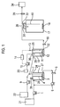
- Figure 1 illustrates a dissolution test apparatus of the present invention
- Figure 2 illustrates a dip-tube and Tee assembly utilized in the apparatus of the present invention
- Figure 3 illustrates a top-plan view of the base of the cell utilized in the apparatus of the present invention.
- Figure 4 illustrates a side-sectional view of the base of the cell utilizing the filter support of the present invention.
- the present invention provides a new dissolution testing apparatus and methods for testing that incorporate disintegration, solids transfer, dissolution, changing pH/composition of fluids, absorption, and clearance.
- the present invention provides excellent Level A IVIVC and is predictive across different dosage forms of the same drug.
- no mathematical model is required.
- the present invention provides an improved filtration system including a filter support that prevents the filter membrane from deforming or distorting (from the increased pressure) into the molded shape of the ridges on the base of the cell. According to the invention, the addition of the filter support prevents the distortion of the filter membrane and allows for the continuous, unrestricted flow of the media through the cells and throughout the apparatus.
- Figure 1 illustrates one embodiment of the dissolution apparatus of the present invention.
- a reservoir 21, a pump 1, and a filtration cell 2 are connected such that the liquid contents (media) of the reservoir 21 is transferred into the filtration cell 2 via the pump 1.
- the filtration cell 2 is equipped with a tight fitting lid 24, a filtration membrane 3, a stirrer 4, an inlet 28, an outlet 47 positioned to allow removal of filtered liquid, a sample holder 38, and a dip-tube and Tee assembly 7.
- the outlet 47 is connected to a flow-thru uv cell 5 and pump 6, such that the filtrate is pumped through the uv cell 5 and returned to the inlet 28 of the filtration cell 2.
- One branch of the dip-tube and Tee assembly 7 comprises a dip-tube to allow removal of liquid and small particle sized solids from the filtration cell 2.
- the second branch of the dip tube and Tee assembly is connected to the outlet of a pump 9.
- the third branch of the dip-tube and Tee assembly 7 is connected to the inlet 29 of a second filtration cell 10.
- a reservoir 22 is connected to the pump 9 such that the liquid media from the reservoir 22 is fed into the second branch of the dip-tube and Tee assembly 7.
- the filtration cell 10 is equipped with a tight fitting lid 25, a pH sensor 13, a stirrer 11, a filtration membrane 12, two inlets 29 and 30 , and an outlet positioned to allow removal of filtered liquid.
- a reservoir 23 is connected to a pump 15 and to one of the inlets 30 of the filtration cell 10, such that liquid from the reservoir 23 is transferred into the filtration cell 10.
- the outlet 47 is connected to a flow-thru uv cell 16.
- the outlet of the uv cell 16 is connected to the inlet 31 of the cell 17.
- the pH sensor 13 is electrically connected to a pH controller 14.
- the power supply to pump 15 is connected to the output relay of the pH controller 14 such that the pump 15 is turned on when the pH, as measured by the pH sensor 13, is below a target value, and is turned off when the pH is above a target value.
- the cell 17 is equipped with a tight fitting lid 26, a stirrer 18, a dip-tube 19, and an outlet 33.
- the outlet is connected to the inlet of a flow-thru uv cell 20.
- the outlet from the uv cell 20 is directed to waste or any suitable reservoir 34.
- the filtration cell 2 and immediately associated equipment represents the gastric chamber; the filtration cell 10 and immediately associated equipment represents the intestinal chamber; the cell 17 and immediately associated equipment represents the circulatory chamber.
- Each of the flow-thru uv cells 5, 16, and 20 is placed in a suitable uv spectrophotometer capable of measuring the absorbance of the cell contents at the desired wavelength.
- FIG. 2 schematically illustrates one embodiment of the mixing device herein called a dip-tube and Tee assembly.
- the dip-tube and Tee assembly 7 comprises a Y-shaped connector 35, a length of tubing 36, and a sealant 37.
- the tubing 36 is inserted into one of the branches of the connector 35 together with a sealant to prevent leakage of liquid media and to hold the tubing in place during operation.
- the length of the tubing is adjusted so that the lower end is below the surface of the liquid when the equipment is operating. This arrangement allows the transfer of small particles between the gastric (first chamber) and intestinal chambers (second chamber) without clogging the tubing. Large particles are not transferred by this arrangement because they are too large to enter the dip tube or because the flow velocity of the medium in the dip tube is insufficient to carry the large particles up the dip tube.
- any or all of the three cells can be immersed in a suitable heating bath or a recirculating hot air oven.
- reservoir 21 is filled with simulated gastric fluid
- reservoir 22 is filled with simulated intestinal fluid
- reservoir 23 is filled with 0.8M aqueous sodium hydroxide solution.
- the pumps are operated to fill each of the chambers to the desired volumes, and then run for sufficient time to establish that the flow rate from each pump is as desired, the temperature is as desired and the pH of cell 10 is maintained within the target range.
- the uv cells are checked to make sure that they contain no air bubbles.
- the sample in the sample holder 38 is lowered into the filtration cell 2, down to a fixed distance within the cell 2.
- the sample is introduced into the cell 2 without stopping/starting the pumps. Exposure to the fluid in the gastric chamber causes the sample to be partially or completely disintegrated, or dispersed or dissolved. The dissolved portion exits the gastric chamber via the tube 36 together with small particles of undissolved drug and/or excipient. Dissolved drug and/or dissolved excipient also exits the gastric chamber through the outlet 47.
- the filter membrane 45 prevents undissolved particles from exiting through the outlet 47.
- the liquid that exits though outlet 47 passes through the uv cell 5, where it's uv absorbance at any desired wavelength is continuously monitored.
- the liquid is continuously returned to the gastric chamber via the inlet 28.
- the material exiting via the tube 36 enters the Tee 35 where it mixes with simulated intestinal fluid from the pump 9. This mixture then enters the simulated intestinal chamber via the inlet 29.
- FIG. 3 there is shown a top-plan view of the base 44 of the cell 2 of the present invention.
- the base 44 has ridges 48 to promote the free flow of the media that is received from the reservoir 21, and pumped out through the outlet 47.
- the ridges 48 provide voids or spaces, in which the media can gather or collect and then exit through the outlet 47. Restricting or reducing the voids or spaces will diminish the media flow, and perhaps cause complete blockage.
- the ridges 48 are shown in a circular pattern, any desired pattern that promotes media/solvent flow is acceptable.
- FIG. 4 illustrates a side-sectional view of the base 44 of the cell 2 of the present invention.
- the filter membrane 45 is provided over the base of the cell 44, in particular, over ridges 48.
- the filter membrane 45 is firmly held in place by a retainer ring, preferably, an O-ring.
- the media flows through the filter membrane 45, into the ridges 48 and then exits toward the outlet 47.
- the filter support 46 is provided between the ridges 48 and the filter membrane 45, preventing the filter 45 from deforming or distorting (from the increased pressure) into the molded shape of the ridges 48. In other words, as the pressure increases within the system, there is a tendency for the filter 45 to be pulled into the base of the cell 44.
- the filter 45 there is a tendency for the filter 45 to "fill-in" the ridges 48 of the base of the cell 44, impeding or restricting the flow of the media within the ridges 48.
- the addition of the rigid filter support 46 prevents the distortion of the filter membrane 45 and allows for the continuous, unrestricted flow of the media through the cell 2 and throughout the apparatus.
- the filter support 46 may be any material that is at least less flexible than the filter membrane 45.
- the support 46 is a metal mesh screen.
- the incoming mixture is mixed with the contents of the chamber together with sodium hydroxide solution entering from pump 15. Because the sodium hydroxide flow is controlled by the pH of the contents of the cell 10 the result is that the acid present in the gastric fluid portion of the incoming mixture is neutralized.
- the undissolved portion of the incoming mixture has further opportunity to dissolve. Dissolved drug and/or dissolved excipient exits the intestinal chamber through the outlet 47.
- the filter membrane 45 prevents any undissolved drug and/or undissolved excipient from exiting the chamber.
- the liquid that exits though outlet 47 passes through the uv cell 16, where it's uv absorbance at any desired wavelength is continuously monitored. The liquid exiting the uv cell 16 then enters the circulatory chamber via the inlet 31.
- the intestinal chamber (cell 10) is also provided with the filter support 46 of the present invention.
- FIG 3 there is also shown a top-plan view of the base 44 of the cell 10 of the present invention.
- the base 44 has ridges 48 to promote the free flow of the media that is received from the reservoir 22, and pumped out through the outlet 47.
- the ridges 48 provide voids or spaces, in which the media can gather or collect and then exit through the outlet 47. Restricting or reducing the voids or spaces will diminish the media flow, and perhaps cause complete blockage.
- the ridges 48 are shown in a circular pattern, any desired pattern that promotes media/solvent flow is acceptable.
- FIG. 4 there is shown a side-sectional view of the base 44 of the cell 10 of the present invention.
- the filter membrane 45 is provided over the base of the cell 44, in particular, over ridges 48.
- the filter membrane 45 is firmly held in place by a retainer ring, preferably, an O-ring.
- the media flows through the filter membrane 45, into the ridges 48 and then exits toward the outlet 47.
- the filter support 46 is provided between the ridges 48 and the filter membrane 45, preventing the filter 45 from deforming or distorting (from the increased pressure) into the molded shape of the ridges 48. In other words, as the pressure increases within the system, there is a tendency for the filter 45 to be pulled into the base of the cell 44.
- the filter 45 there is a tendency for the filter 45 to "fill-in" the ridges 48 of the base of the cell 44, impeding or restricting the flow of the media within the ridges 48.
- the addition of the rigid filter support 46 prevents the distortion of the filter membrane 45 and allows for the continuous, unrestricted flow of the media through the cell 10 and throughout the apparatus.
- the filter support 46 may be any material that is at least less flexible than the filter membrane 45.
- the support 46 is a metal mesh screen.
- a filtration system including a filter support 46 in both the gastric chamber (cell 2) and the intestinal chamber (cell 10)
- a filtration system is solely provided in the intestinal chamber to prevent any solids from entering the circulatory system (cell 17).
- the incoming medium is mixed with the medium already present in the chamber.
- the resulting mixture continuously exits the chamber via the dip-tube 19 and outlet 33.
- the liquid that exits though outlet 33 passes through the uv cell 20, where the uv absorbance at any desired wavelength is continuously monitored.
- the data collected from the spectrophotometer can be used to calculate the instantaneous concentration of the active substance.
- the data can be used to characterize the release rate and the total amount of active substance released. Measuring the concentration of active substance in the effluent collected in the collection reservoir 34 permits the calculation of the total amount of active substance released.
- compositions can be changed with time to simulate changing conditions within the body.
- Test method variables are, for example, composition of release media, residence time in each of the three chambers, amount of the sample being tested, and temperature. By adjusting these variables it is possible to obtain a release rate profile that matches the plasma concentration profile observed in vivo.
- the preferred temperature is 37° C.
- the preferred composition of the release media are simulated gastric and simulated intestinal fluids.
- the present invention can be adapted for conditions that are not physiologically relevant. Such conditions may be desirable when considerations such as speed of operation, unusual solubility, or non conventional dosage forms are taken into account. For example, applicant has determined in some cases that by proportionally reducing residence times, the time scale of the test can be considerably shortened without loss of useful information.
- the invention can be used to test many different types of formulations. These can include, but are not restricted to, tablets, powders, pills, syrups; fast-melt tablets, hard capsules and soft capsules.
- the medium analysis device includes, but is not limited to, any detector known in the art that generates physical and/or chemical data of a pharmaceutical or active test agent, e.g., the use of a UV spectrophotometer as the method of analysis.
- the detector is capable of acquiring data characteristic of a particular agent by any method, including, ultraviolet radiation, infrared radiation, nuclear magnetic resonance, Ramen spectroscopy, electrochemical, biosensors, refractometry, optical activity, and combinations thereof.
- any in-line detector known in the art that is applicable to the active substance and release medium can be used.
- the medium dissolution analysis device is a detector that has a sensor communicatively attached thereto.
- the medium analysis device preferably includes a detector operatively associated with the dissolution medium for at least the time period required for the dosage form to release the maximum releasable quantity of therapeutically active agent and a data processor for continually processing the generated data for at least the time period required for the dosage form to release the maximum releasable quantity of therapeutically active agent to obtain a dissolution profile of the dosage form.
- the data processor may be any device capable of continuously processing the data generated by the detector.
- the data processor is a computer.
- the data generated by the detector is preferably stored and/or analyzed by the computer.
- the data collector is a computer that has data processing software. The data is preferably continuously processed by the software as it is received from the detector.
- the detector measures the concentration of the therapeutically active agent in the media surrounding the dosage form such as in simulated gastric or intestinal fluid. By measuring the concentration of the agent in the surrounding media, the amount of agent released from the dosage form can be calculated.
- the invention can also be used by removing samples from the chambers directly or from the effluent discharge of the chambers instead of, or in addition to in-line analysis.
- the analytical methods can be any method known in the art, including but not limited to, Gas chromatography, liquid chromatography, high performance liquid chromatography (HPLC), colorimetry, uv spectroscopy, IR spectroscopy, Raman spectroscopy, near IR spectroscopy, bio-sensors, electrochemical methods, mass spectroscopy, and nuclear magnetic spectroscopy.
- the medium analysis is performed in- line using uv spectroscopy.
- any combination of the medium analysis devices can be used as appropriate for the data required.
- the absorption of active substance in the stomach can be simulated by not returning to the gastric chamber, all or part of the medium exiting the gastric chamber via the second outlet.
- the flow rate of the medium can be adjusted so that the removal rate corresponds to the in vivo gastric absorption.
- the filtration cells 2 and 10 can be of any design that provides the requirements of agitation, desired volume, filtration speed, filtration efficiency, and compatibility with the active substance and the release media.
- the preferred filtration cells are continuous and stirred, filtration cells (e.g., Amicon stirred ultrafiltration cell models 8003, 8010, 8050, 8200, and 8400 available from Millipore Corporation).
- the third cell 17 can be of any design that provides the requirements of agitation, desired volume, and compatibility with the active substance and the release media.
- the pumps useful in the practice of the present invention can be any pump capable of attaining the desired flow rate and maintaining the flow rate constant throughout the test. These include but are not limited to, general purpose positive displacement pumps, peristaltic pumps, diaphragm pumps, HPLC quality positive displacement pumps, syringe pumps and centrifugal pumps.
- Preferred pumps useful in the invention are peristaltic pumps, diaphragm pumps, and HPLC quality positive displacement pumps. Most preferred are peristaltic pumps and HPLC quality positive displacement pumps.
- Heating devices useful in the practice of the present invention can be any of those known in the art that give sufficiently uniform and accurate temperature control.
- the preferred heating device will be able to control the temperature to within +/-2° C. of the desired temperature.
- the more preferred heating device will be able to control the temperature to within +/-1° C. of the desired temperature.
- the most preferred heating device will be able to control the temperature in conformity with the most current recommendations in the US Pharmacopeia and like sources.
- the tubing used in the dip-tube and Tee assembly can be any tubing compatible with the release medium and the test sample.
- the length of the tubing is adjusted such that the lower end is below the surface of the liquid in the filtration cell 2.
- the cross-sectional diameter of the tubing is selected so that small particles are carried up the tubing by the flow of the release medium and so that particles do not clog the tubing.
- tubing with an internal diameter of 0.5 to 3.0 mm fulfills these requirements for flow rates to the cell 2 in the range 0.5 to 2.5 m/min. For other flow rates other internal diameters may be needed.
- the medium analysis sensor and controller used with the intestinal chamber can be any combination of sensor and controller that measures and permits control of physical characteristics such as, but not limited to, pH, osmolarity, conductivity, and concentration of specific ions.
- the preferred medium analysis sensor and controller are any pH sensor and pH controller available in the art that permit the control of the pH in the intestinal chamber to within the target range.
- the most preferred medium analysis sensor and controller are any pH sensors and pH controllers available in the art that has an accuracy of +/-0.02 pH units.
- the pH in the second cell 10 is controlled to the same value as that of the simulated intestinal fluid.
- the pH in the cell can be any value achievable by addition of either an acid or a base through the delivery system defined by the reservoir 23, the pump 15, and the inlet 30, and is not limited to the pH of the fluid in the reservoir 22.
- the solution used to adjust the pH of the second cell 10 can be acidic or basic.
- the preferred concentration of acid or base in the solution is one that requires a flow rate of the solution to be not more than 10% of the total flow of the other release media.
- the most preferred concentration of acid or base in the solution is one that requires a flow rate of the solution to be not more than 2% of the total flow of the other release media.
- the number of cells used in the equipment can be varied depending on the information required. Three cells, as described in one embodiment above, is the preferred number when correlation with blood plasma concentration data is required.
- drug absorption rate data it is only necessary to operate the combination of gastric and intestinal chambers.
- a further possibility is to add a buccal dissolution cell before the gastric chamber such that the effluent from the buccal dissolution chamber enters an inlet in the gastric chamber. Note, the sample holder would be present on the buccal dissolution chamber, not the gastric chamber. The addition can be used for either drug absorption or blood plasma concentration data.
- filter membranes useful in the practice of this invention can be any of the commercially available filter membranes that are compatible with the release media.
- Preferred filter membranes have a nominal particle size cut-off of not more than 10 microns.
- the more preferred filters have a nominal particle size cut-off of 0.25-5 microns.
- the most preferred filter membranes have a nominal particle size cut-off of 1-3 microns.
- Residence times in each of the chambers useful in the practice of this invention can be any value required to give a Level A IVIVC.
- the preferred residence times are those that have physiological relevance. The Applicants have determined by experimentation that the following ranges of residence times are useful: gastric chamber, 5-60 minutes; intestinal chamber, 1-90 minutes; circulatory chamber, greater than 30 minutes.
- various other mechanical, electrical and electronic equipment may be incorporated into the present invention.
- the equipment includes, but is not limited to, pressure relief valves, check valves, pressure relief piping, pressure control systems, surge suppressors, surge tanks, de-aerators, electronic flow control systems, proportional control systems, pressure gauges, heat exchanges (to preheat media) and flow gauges.
- the present invention provides a new dissolution testing apparatus and methods for testing that incorporate disintegration, solids transfer, dissolution, changing pH/composition of fluids, absorption, and clearance.
- the present invention provides excellent Level A IVIVC and appears to be predictive across different dosage forms of the same drug.
- no mathematical model is required.
- the present invention provides a filter support that prevents the distortion of the filter membrane and allows for the continuous, unrestricted flow of the media through the cells and throughout the apparatus, resulting in a more reliable and accurate IVIVC.
Landscapes
- Life Sciences & Earth Sciences (AREA)
- Health & Medical Sciences (AREA)
- Chemical & Material Sciences (AREA)
- Analytical Chemistry (AREA)
- Pathology (AREA)
- Immunology (AREA)
- General Physics & Mathematics (AREA)
- General Health & Medical Sciences (AREA)
- Biochemistry (AREA)
- Physics & Mathematics (AREA)
- Engineering & Computer Science (AREA)
- Biophysics (AREA)
- Medicinal Chemistry (AREA)
- Food Science & Technology (AREA)
- Pharmacology & Pharmacy (AREA)
- Molecular Biology (AREA)
- Bioinformatics & Cheminformatics (AREA)
- Investigating Or Analysing Biological Materials (AREA)
- Sampling And Sample Adjustment (AREA)
Abstract
Description
- The rate at which pharmaceutically active compounds dissolve in gastrointestinal fluids is crucial in the design and use of orally administered medications. The active compound must be dissolved before it can be absorbed by the body. The rate at which the active substance enters into solution is know in the art as the dissolution rate, and the determination of the dissolution rate in vitro is known as dissolution testing.
- Dissolution testing provides a better understanding of the amount of a pharmaceutically active compound available at a particular absorption site at various times. In addition, establishing a relationship between dosage form and availability of a pharmaceutically active compounds at certain absorption sites and systemic blood levels of such active compound aids in the development of specialized delivery techniques.
- The concept of using in vitro data to predict or model in vivo behavior, referred to as in vitro-in vivo correlation, or IVIVC, is of great interest in the pharmaceutical arts. Test methods with good IVIVC are better for detecting problems with existing formulations and in the development of new formulations. Systems that correlate closely with the dissolution and absorption data obtained in vivo can be used in developing dosage forms as well as in the production, scale-up, determination of lot-to-lot variability, testing of new dosage strengths, testing of minor formulation changes, testing after changes in the site of manufacture and for determining bio-equi valence.
- In
U.S. Pat. No. 4,335,438 to Smolen , it describes a dissolution test method utilizing a combination of a flow-through cell (with recycle) and a mathematical model. The mathematical model is used in conjunction with varying test parameters in order to provide an optimized in vivo plasma curve from the in vitro data. In Smolen, there are four basic variables, flow rate, amount of recycle, pH, and stirring rate that are necessarily changed with time so that the number of possible combinations of variables is increased. Unfortunately, the results obtained using the Smolen cell, based on USFDA guidelines, are not an acceptable for establishing IVIVC because the number of independent variables are too great. In other words, the dissolution test method of Smolen may not be physiologically relevant. In addition, the flow-through system of Smolen utilizes only one cell per test, further compromising the IVIVC. - Thus, there is a need for an integrated assessment of in vitro dissolution of a pharmaceutical formulation and absorption of an active compound from such formulation, especially with the development of more advanced dosage forms, for example, formulations that provide a delayed release of a compound. Also, there is need for an in vitro dissolution test that takes into account the absorption of the active substance by the body and the presence of dissolved active substance during the dissolution. Further, there is also a need for an in vitro dissolution test that is able to demonstrate Level A IVIVC without the need for mathematical models to transform the in vitro data.
- In a first aspect of the present invention, there is provided a dissolution test apparatus comprising: a first chamber connected in series to at least a second chamber, wherein the first chamber is capable of transferring solid test samples to the second chamber and the second chamber is capable of retaining the solid test samples; a first reservoir and at least a second reservoir for continuously supplying one or more media into the first chamber and the second chamber, respectively, the chambers having a stirrer for mixing the solid test samples and the media together; wherein the second chamber has a filter membrane overlying a base of the second chamber, the filter membrane being supported by a filter support, the filter support being provided between the filter membrane and the base of the second chamber to prevent distortion of the filter membrane; and a processor for analyzing an effluent from the chambers.
- In another aspect of the present invention, there is provided a dissolution test apparatus comprising: a first chamber connected in series to at least a second chamber, wherein the first chamber is capable of transferring solid test samples to the second chamber and the second chamber is capable of retaining the solid test samples; a first reservoir and at least a second reservoir for continuously supplying one or more media into the first chamber and the second chamber, respectively; a filter membrane provided in a base of the first and second chambers, the base having ridges formed thereon; a filter support provided over the ridges to prevent distortion of the filter membrane; and a processor for analyzing an effluent from the chambers.
- In another aspect of the present invention, there is provided a method for dissolution testing comprising: transferring solid test samples from a first chamber connected in series to at least a second chamber, wherein the second chamber is capable of retaining the solid test samples; continuously supplying one or more media into the first chamber and the second chamber from a first reservoir and at least a second reservoir, respectively; mixing the solid test samples and the media together; filtering the solid test samples through a filter membrane supported by a filter support, the filter support overlying a base of the first and second chambers to prevent distortion of the filter membrane; and analyzing an effluent from the chambers.
- Figure 1 illustrates a dissolution test apparatus of the present invention;
- Figure 2 illustrates a dip-tube and Tee assembly utilized in the apparatus of the present invention;
- Figure 3 illustrates a top-plan view of the base of the cell utilized in the apparatus of the present invention; and
- Figure 4 illustrates a side-sectional view of the base of the cell utilizing the filter support of the present invention.
- The present invention provides a new dissolution testing apparatus and methods for testing that incorporate disintegration, solids transfer, dissolution, changing pH/composition of fluids, absorption, and clearance. The present invention provides excellent Level A IVIVC and is predictive across different dosage forms of the same drug. In addition, no mathematical model is required. Also, the present invention provides an improved filtration system including a filter support that prevents the filter membrane from deforming or distorting (from the increased pressure) into the molded shape of the ridges on the base of the cell. According to the invention, the addition of the filter support prevents the distortion of the filter membrane and allows for the continuous, unrestricted flow of the media through the cells and throughout the apparatus.
- Referring now to the drawings, Figure 1 illustrates one embodiment of the dissolution apparatus of the present invention. A
reservoir 21, apump 1, and afiltration cell 2 are connected such that the liquid contents (media) of thereservoir 21 is transferred into thefiltration cell 2 via thepump 1. Thefiltration cell 2 is equipped with atight fitting lid 24, afiltration membrane 3, a stirrer 4, aninlet 28, anoutlet 47 positioned to allow removal of filtered liquid, asample holder 38, and a dip-tube and Tee assembly 7. Theoutlet 47 is connected to a flow-thru uv cell 5 and pump 6, such that the filtrate is pumped through theuv cell 5 and returned to theinlet 28 of thefiltration cell 2. One branch of the dip-tube and Tee assembly 7 comprises a dip-tube to allow removal of liquid and small particle sized solids from thefiltration cell 2. The second branch of the dip tube and Tee assembly is connected to the outlet of apump 9. The third branch of the dip-tube and Tee assembly 7 is connected to theinlet 29 of asecond filtration cell 10. - A
reservoir 22 is connected to thepump 9 such that the liquid media from thereservoir 22 is fed into the second branch of the dip-tube and Tee assembly 7. Thefiltration cell 10 is equipped with atight fitting lid 25, apH sensor 13, astirrer 11, afiltration membrane 12, twoinlets reservoir 23 is connected to apump 15 and to one of theinlets 30 of thefiltration cell 10, such that liquid from thereservoir 23 is transferred into thefiltration cell 10. Theoutlet 47 is connected to a flow-thru uv cell 16. The outlet of theuv cell 16 is connected to theinlet 31 of thecell 17. ThepH sensor 13 is electrically connected to apH controller 14. The power supply topump 15 is connected to the output relay of thepH controller 14 such that thepump 15 is turned on when the pH, as measured by thepH sensor 13, is below a target value, and is turned off when the pH is above a target value. - The
cell 17 is equipped with atight fitting lid 26, astirrer 18, a dip-tube 19, and anoutlet 33. The outlet is connected to the inlet of a flow-thru uv cell 20. The outlet from theuv cell 20 is directed to waste or anysuitable reservoir 34. In this embodiment, thefiltration cell 2 and immediately associated equipment represents the gastric chamber; thefiltration cell 10 and immediately associated equipment represents the intestinal chamber; thecell 17 and immediately associated equipment represents the circulatory chamber. Each of the flow-thru uv cells - Figure 2 schematically illustrates one embodiment of the mixing device herein called a dip-tube and Tee assembly. The dip-tube and Tee assembly 7 comprises a Y-
shaped connector 35, a length oftubing 36, and asealant 37. Thetubing 36 is inserted into one of the branches of theconnector 35 together with a sealant to prevent leakage of liquid media and to hold the tubing in place during operation. The length of the tubing is adjusted so that the lower end is below the surface of the liquid when the equipment is operating. This arrangement allows the transfer of small particles between the gastric (first chamber) and intestinal chambers (second chamber) without clogging the tubing. Large particles are not transferred by this arrangement because they are too large to enter the dip tube or because the flow velocity of the medium in the dip tube is insufficient to carry the large particles up the dip tube. - When control of the temperature is required any or all of the three cells can be immersed in a suitable heating bath or a recirculating hot air oven. In one embodiment,
reservoir 21 is filled with simulated gastric fluid,reservoir 22 is filled with simulated intestinal fluid, andreservoir 23 is filled with 0.8M aqueous sodium hydroxide solution. To start a test, the pumps are operated to fill each of the chambers to the desired volumes, and then run for sufficient time to establish that the flow rate from each pump is as desired, the temperature is as desired and the pH ofcell 10 is maintained within the target range. The uv cells are checked to make sure that they contain no air bubbles. In one embodiment, the sample in thesample holder 38 is lowered into thefiltration cell 2, down to a fixed distance within thecell 2. Note, the sample is introduced into thecell 2 without stopping/starting the pumps. Exposure to the fluid in the gastric chamber causes the sample to be partially or completely disintegrated, or dispersed or dissolved. The dissolved portion exits the gastric chamber via thetube 36 together with small particles of undissolved drug and/or excipient. Dissolved drug and/or dissolved excipient also exits the gastric chamber through theoutlet 47. Thefilter membrane 45 prevents undissolved particles from exiting through theoutlet 47. The liquid that exits thoughoutlet 47 passes through theuv cell 5, where it's uv absorbance at any desired wavelength is continuously monitored. The liquid is continuously returned to the gastric chamber via theinlet 28. The material exiting via thetube 36 enters theTee 35 where it mixes with simulated intestinal fluid from thepump 9. This mixture then enters the simulated intestinal chamber via theinlet 29. - Referring now to Figure 3, there is shown a top-plan view of the
base 44 of thecell 2 of the present invention. As shown, thebase 44 has ridges 48 to promote the free flow of the media that is received from thereservoir 21, and pumped out through theoutlet 47. In other words, the ridges 48 provide voids or spaces, in which the media can gather or collect and then exit through theoutlet 47. Restricting or reducing the voids or spaces will diminish the media flow, and perhaps cause complete blockage. Note, although the ridges 48 are shown in a circular pattern, any desired pattern that promotes media/solvent flow is acceptable. - Figure 4 illustrates a side-sectional view of the
base 44 of thecell 2 of the present invention. As illustrated, thefilter membrane 45 is provided over the base of thecell 44, in particular, over ridges 48. Thefilter membrane 45 is firmly held in place by a retainer ring, preferably, an O-ring. The media flows through thefilter membrane 45, into the ridges 48 and then exits toward theoutlet 47. Advantageously, thefilter support 46 is provided between the ridges 48 and thefilter membrane 45, preventing thefilter 45 from deforming or distorting (from the increased pressure) into the molded shape of the ridges 48. In other words, as the pressure increases within the system, there is a tendency for thefilter 45 to be pulled into the base of thecell 44. In particular, there is a tendency for thefilter 45 to "fill-in" the ridges 48 of the base of thecell 44, impeding or restricting the flow of the media within the ridges 48. However, according to the invention, the addition of therigid filter support 46 prevents the distortion of thefilter membrane 45 and allows for the continuous, unrestricted flow of the media through thecell 2 and throughout the apparatus. Thefilter support 46 may be any material that is at least less flexible than thefilter membrane 45. Preferably, thesupport 46 is a metal mesh screen. - In the intestinal chamber, the incoming mixture is mixed with the contents of the chamber together with sodium hydroxide solution entering from
pump 15. Because the sodium hydroxide flow is controlled by the pH of the contents of thecell 10 the result is that the acid present in the gastric fluid portion of the incoming mixture is neutralized. In the intestinal chamber the undissolved portion of the incoming mixture has further opportunity to dissolve. Dissolved drug and/or dissolved excipient exits the intestinal chamber through theoutlet 47. Thefilter membrane 45 prevents any undissolved drug and/or undissolved excipient from exiting the chamber. The liquid that exits thoughoutlet 47 passes through theuv cell 16, where it's uv absorbance at any desired wavelength is continuously monitored. The liquid exiting theuv cell 16 then enters the circulatory chamber via theinlet 31. - Note, the intestinal chamber (cell 10) is also provided with the
filter support 46 of the present invention. Referring back to Figure 3, there is also shown a top-plan view of thebase 44 of thecell 10 of the present invention. As shown, thebase 44 has ridges 48 to promote the free flow of the media that is received from thereservoir 22, and pumped out through theoutlet 47. In other words, the ridges 48 provide voids or spaces, in which the media can gather or collect and then exit through theoutlet 47. Restricting or reducing the voids or spaces will diminish the media flow, and perhaps cause complete blockage. Note, although the ridges 48 are shown in a circular pattern, any desired pattern that promotes media/solvent flow is acceptable. - Also, referring back to Figure 4, there is shown a side-sectional view of the
base 44 of thecell 10 of the present invention. As illustrated, thefilter membrane 45 is provided over the base of thecell 44, in particular, over ridges 48. Thefilter membrane 45 is firmly held in place by a retainer ring, preferably, an O-ring. The media flows through thefilter membrane 45, into the ridges 48 and then exits toward theoutlet 47. Advantageously, thefilter support 46 is provided between the ridges 48 and thefilter membrane 45, preventing thefilter 45 from deforming or distorting (from the increased pressure) into the molded shape of the ridges 48. In other words, as the pressure increases within the system, there is a tendency for thefilter 45 to be pulled into the base of thecell 44. In particular, there is a tendency for thefilter 45 to "fill-in" the ridges 48 of the base of thecell 44, impeding or restricting the flow of the media within the ridges 48. However, according to the invention, the addition of therigid filter support 46 prevents the distortion of thefilter membrane 45 and allows for the continuous, unrestricted flow of the media through thecell 10 and throughout the apparatus. Thefilter support 46 may be any material that is at least less flexible than thefilter membrane 45. Preferably, thesupport 46 is a metal mesh screen. Note, although invention has been described with a filtration system (including a filter support 46) in both the gastric chamber (cell 2) and the intestinal chamber (cell 10), typically, a filtration system is solely provided in the intestinal chamber to prevent any solids from entering the circulatory system (cell 17). - In the circulatory chamber, the incoming medium is mixed with the medium already present in the chamber. The resulting mixture continuously exits the chamber via the dip-
tube 19 andoutlet 33. The liquid that exits thoughoutlet 33 passes through theuv cell 20, where the uv absorbance at any desired wavelength is continuously monitored. The data collected from the spectrophotometer can be used to calculate the instantaneous concentration of the active substance. The data can be used to characterize the release rate and the total amount of active substance released. Measuring the concentration of active substance in the effluent collected in thecollection reservoir 34 permits the calculation of the total amount of active substance released. - While the embodiment of the invention described above uses constant composition of release fluids, the compositions can be changed with time to simulate changing conditions within the body. Test method variables are, for example, composition of release media, residence time in each of the three chambers, amount of the sample being tested, and temperature. By adjusting these variables it is possible to obtain a release rate profile that matches the plasma concentration profile observed in vivo. When practiced in the pharmaceutical industry, the preferred temperature is 37° C., and the preferred composition of the release media are simulated gastric and simulated intestinal fluids.
- Also, other additives, such as enzymes, bile acids, and surfactants, can be included, as desired. In addition, although the USFDA recommends that dissolution conditions be physiologically relevant, the present invention can be adapted for conditions that are not physiologically relevant. Such conditions may be desirable when considerations such as speed of operation, unusual solubility, or non conventional dosage forms are taken into account. For example, applicant has determined in some cases that by proportionally reducing residence times, the time scale of the test can be considerably shortened without loss of useful information. In addition, the invention can be used to test many different types of formulations. These can include, but are not restricted to, tablets, powders, pills, syrups; fast-melt tablets, hard capsules and soft capsules.
- The medium analysis device includes, but is not limited to, any detector known in the art that generates physical and/or chemical data of a pharmaceutical or active test agent, e.g., the use of a UV spectrophotometer as the method of analysis. In a preferred embodiment, the detector is capable of acquiring data characteristic of a particular agent by any method, including, ultraviolet radiation, infrared radiation, nuclear magnetic resonance, Ramen spectroscopy, electrochemical, biosensors, refractometry, optical activity, and combinations thereof. Also, any in-line detector known in the art that is applicable to the active substance and release medium can be used. Preferably, the medium dissolution analysis device is a detector that has a sensor communicatively attached thereto. In the preferred embodiment, there is at least one medium dissolution analysis device per dissolution chamber. For example, for each sample to be analyzed there is a corresponding medium dissolution analysis device capable of continuously generating physical and/or chemical data characteristic of the agent to be analyzed.
- The medium analysis device preferably includes a detector operatively associated with the dissolution medium for at least the time period required for the dosage form to release the maximum releasable quantity of therapeutically active agent and a data processor for continually processing the generated data for at least the time period required for the dosage form to release the maximum releasable quantity of therapeutically active agent to obtain a dissolution profile of the dosage form. The data processor may be any device capable of continuously processing the data generated by the detector. In a preferred embodiment, the data processor is a computer. The data generated by the detector is preferably stored and/or analyzed by the computer. In a particularly preferred embodiment, the data collector is a computer that has data processing software. The data is preferably continuously processed by the software as it is received from the detector.
- In the preferred embodiment of the present invention, the detector measures the concentration of the therapeutically active agent in the media surrounding the dosage form such as in simulated gastric or intestinal fluid. By measuring the concentration of the agent in the surrounding media, the amount of agent released from the dosage form can be calculated. The invention can also be used by removing samples from the chambers directly or from the effluent discharge of the chambers instead of, or in addition to in-line analysis. In such an embodiment the analytical methods can be any method known in the art, including but not limited to, Gas chromatography, liquid chromatography, high performance liquid chromatography (HPLC), colorimetry, uv spectroscopy, IR spectroscopy, Raman spectroscopy, near IR spectroscopy, bio-sensors, electrochemical methods, mass spectroscopy, and nuclear magnetic spectroscopy. In the most preferred embodiment the medium analysis is performed in- line using uv spectroscopy.
- In the present invention, any combination of the medium analysis devices can be used as appropriate for the data required. In another embodiment the absorption of active substance in the stomach can be simulated by not returning to the gastric chamber, all or part of the medium exiting the gastric chamber via the second outlet. The flow rate of the medium can be adjusted so that the removal rate corresponds to the in vivo gastric absorption.
- The
filtration cells - The
third cell 17 can be of any design that provides the requirements of agitation, desired volume, and compatibility with the active substance and the release media. The pumps useful in the practice of the present invention can be any pump capable of attaining the desired flow rate and maintaining the flow rate constant throughout the test. These include but are not limited to, general purpose positive displacement pumps, peristaltic pumps, diaphragm pumps, HPLC quality positive displacement pumps, syringe pumps and centrifugal pumps. Preferred pumps useful in the invention are peristaltic pumps, diaphragm pumps, and HPLC quality positive displacement pumps. Most preferred are peristaltic pumps and HPLC quality positive displacement pumps. - Heating devices useful in the practice of the present invention can be any of those known in the art that give sufficiently uniform and accurate temperature control. The preferred heating device will be able to control the temperature to within +/-2° C. of the desired temperature. The more preferred heating device will be able to control the temperature to within +/-1° C. of the desired temperature. The most preferred heating device will be able to control the temperature in conformity with the most current recommendations in the US Pharmacopeia and like sources.
- The tubing used in the dip-tube and Tee assembly can be any tubing compatible with the release medium and the test sample. The length of the tubing is adjusted such that the lower end is below the surface of the liquid in the
filtration cell 2. The cross-sectional diameter of the tubing is selected so that small particles are carried up the tubing by the flow of the release medium and so that particles do not clog the tubing. In practice, the inventors have determined that tubing with an internal diameter of 0.5 to 3.0 mm fulfills these requirements for flow rates to thecell 2 in the range 0.5 to 2.5 m/min. For other flow rates other internal diameters may be needed. - The medium analysis sensor and controller used with the intestinal chamber can be any combination of sensor and controller that measures and permits control of physical characteristics such as, but not limited to, pH, osmolarity, conductivity, and concentration of specific ions. The preferred medium analysis sensor and controller are any pH sensor and pH controller available in the art that permit the control of the pH in the intestinal chamber to within the target range. The most preferred medium analysis sensor and controller are any pH sensors and pH controllers available in the art that has an accuracy of +/-0.02 pH units.
- In the preferred embodiment the pH in the
second cell 10 is controlled to the same value as that of the simulated intestinal fluid. Also, the pH in the the cell can be any value achievable by addition of either an acid or a base through the delivery system defined by thereservoir 23, thepump 15, and theinlet 30, and is not limited to the pH of the fluid in thereservoir 22. The solution used to adjust the pH of thesecond cell 10 can be acidic or basic. The preferred concentration of acid or base in the solution is one that requires a flow rate of the solution to be not more than 10% of the total flow of the other release media. The most preferred concentration of acid or base in the solution is one that requires a flow rate of the solution to be not more than 2% of the total flow of the other release media. - The number of cells used in the equipment can be varied depending on the information required. Three cells, as described in one embodiment above, is the preferred number when correlation with blood plasma concentration data is required. When drug absorption rate data is required it is only necessary to operate the combination of gastric and intestinal chambers. A further possibility is to add a buccal dissolution cell before the gastric chamber such that the effluent from the buccal dissolution chamber enters an inlet in the gastric chamber. Note, the sample holder would be present on the buccal dissolution chamber, not the gastric chamber. The addition can be used for either drug absorption or blood plasma concentration data.
- In addition, filter membranes useful in the practice of this invention can be any of the commercially available filter membranes that are compatible with the release media. Preferred filter membranes have a nominal particle size cut-off of not more than 10 microns. The more preferred filters have a nominal particle size cut-off of 0.25-5 microns. The most preferred filter membranes have a nominal particle size cut-off of 1-3 microns.
- Residence times in each of the chambers useful in the practice of this invention can be any value required to give a Level A IVIVC. The preferred residence times are those that have physiological relevance. The Applicants have determined by experimentation that the following ranges of residence times are useful: gastric chamber, 5-60 minutes; intestinal chamber, 1-90 minutes; circulatory chamber, greater than 30 minutes. In addition, various other mechanical, electrical and electronic equipment may be incorporated into the present invention. For example, the equipment includes, but is not limited to, pressure relief valves, check valves, pressure relief piping, pressure control systems, surge suppressors, surge tanks, de-aerators, electronic flow control systems, proportional control systems, pressure gauges, heat exchanges (to preheat media) and flow gauges.
- Accordingly, the present invention provides a new dissolution testing apparatus and methods for testing that incorporate disintegration, solids transfer, dissolution, changing pH/composition of fluids, absorption, and clearance. The present invention provides excellent Level A IVIVC and appears to be predictive across different dosage forms of the same drug. In addition, no mathematical model is required. Also, the present invention provides a filter support that prevents the distortion of the filter membrane and allows for the continuous, unrestricted flow of the media through the cells and throughout the apparatus, resulting in a more reliable and accurate IVIVC.
Claims (10)
- A dissolution test apparatus comprising:a first chamber connected in series to at least a second chamber, wherein the first chamber is capable of transferring solid test samples to the second chamber and the second chamber is capable of retaining the solid test samples;a first reservoir and at least a second reservoir for continuously supplying one or more media into the first chamber and the second chamber, respectively, the chambers having a stirrer for mixing the solid test samples and the media together;wherein the second chamber has a filter membrane overlying a base of the second chamber, the filter membrane being supported by a filter support, the filter support being provided between the filter membrane and the base of the second chamber to prevent distortion of the filter membrane; and
a processor for analyzing an effluent from the chambers. - The apparatus of claim 1 wherein the first chamber has another filter membrane overlying a base of the first chamber, the another filter membrane being supported by another filter support, the another filter support being provided between the another filter membrane and the base of the first chamber to prevent distortion of the another filter support.
- The apparatus of claim 1 further comprising an O-ring to secure the filter membrane to the base of the second chamber.
- The apparatus of claim 1 wherein the filter support is a metal mesh screen.
- The apparatus of claim 1 wherein the first chamber comprises simulated gastric fluid.
- The apparatus of claim 1 wherein the second chamber comprises simulated intestinal fluid.
- The apparatus of claim 1 further comprising a third chamber connected in series to the second chamber for receiving the effluent from the second chamber.
- The apparatus of claim 1 further comprising a third reservoir connected to the second chamber for supplying a solution for adjusting a pH of the media in the second chamber.
- A dissolution test apparatus comprising:a first chamber connected in series to at least a second chamber, wherein the first chamber is capable of transferring solid test samples to the second chamber and the second chamber is capable of retaining the solid test samples;a first reservoir and at least a second reservoir for continuously supplying one or more media into the first chamber and the second chamber, respectively;a filter membrane provided in a base of the first and second chambers, the base having ridges formed thereon;a filter support provided over the ridges to prevent distortion of the filter membrane; anda processor for analyzing an effluent from the chambers.
- A method for dissolution testing comprising:transferring solid test samples from a first chamber connected in series to at least a second chamber, wherein the second chamber is capable of retaining the solid test samples;continuously supplying one or more media into the first chamber and the second chamber from a first reservoir and at least a second reservoir, respectively;mixing the solid test samples and the media together;filtering the solid test samples through a filter membrane supported by a filter support, the filter support overlying a base of the first and second chambers to prevent distortion of the filter membrane; andanalyzing an effluent from the chambers.
Applications Claiming Priority (1)
| Application Number | Priority Date | Filing Date | Title |
|---|---|---|---|
| US72995405P | 2005-10-25 | 2005-10-25 |
Publications (1)
| Publication Number | Publication Date |
|---|---|
| EP1780528A1 true EP1780528A1 (en) | 2007-05-02 |
Family
ID=37671029
Family Applications (1)
| Application Number | Title | Priority Date | Filing Date |
|---|---|---|---|
| EP06255444A Withdrawn EP1780528A1 (en) | 2005-10-25 | 2006-10-23 | Dissolution test equipment and methods for testing having improved filtration system |
Country Status (6)
| Country | Link |
|---|---|
| US (1) | US20070092404A1 (en) |
| EP (1) | EP1780528A1 (en) |
| JP (1) | JP2007121297A (en) |
| KR (1) | KR100831943B1 (en) |
| CN (1) | CN1955714A (en) |
| TW (1) | TW200732644A (en) |
Families Citing this family (17)
| Publication number | Priority date | Publication date | Assignee | Title |
|---|---|---|---|---|
| WO2008137504A1 (en) * | 2007-05-04 | 2008-11-13 | Smithkline Beecham Corporation | Pharmaceutical analysis apparatus and method |
| US8348673B2 (en) * | 2007-06-11 | 2013-01-08 | Inhalation Sciences Sweden Ab | Device for studying interaction between particles and lungs |
| US7767463B2 (en) * | 2007-06-15 | 2010-08-03 | Cohesive Technologies, Inc. | Method for screening mobile phases in chromatography systems |
| US8147759B2 (en) | 2007-08-29 | 2012-04-03 | Cem Corporation | Automated protein analyzer |
| US8852948B2 (en) * | 2007-08-29 | 2014-10-07 | Cem Corporation | Colorimetric protein analysis method |
| JP5576337B2 (en) | 2010-06-30 | 2014-08-20 | ローム アンド ハース カンパニー | Delivery device for dispensing a pharmaceutical dosage form to a dissolution test device |
| JP5586098B2 (en) | 2010-08-04 | 2014-09-10 | ローム アンド ハース カンパニー | Improved dissolution test equipment |
| CN103018413B (en) * | 2011-09-20 | 2015-03-18 | 中国中医科学院中药研究所 | Drug absorption apparatus |
| CA2957332A1 (en) * | 2014-08-20 | 2016-02-25 | F. Hoffmann-La Roche Ag | In vitro method and apparatus for analysing the behaviour of substances in simulated physiological environment |
| KR20160115091A (en) | 2015-03-26 | 2016-10-06 | 이종임 | a dining table |
| TWI641038B (en) * | 2016-08-02 | 2018-11-11 | Crystalwise Technology Inc. | Polishing liquid supply system |
| WO2019082169A1 (en) * | 2017-10-28 | 2019-05-02 | Hamid Gourabi | Dissolution test for sensitive drugs |
| CN108982806B (en) * | 2018-06-27 | 2021-02-05 | 中广检测技术(广州)有限责任公司 | Soil ion exchange device and method for measuring soil cation exchange capacity |
| JP7261655B2 (en) * | 2019-05-15 | 2023-04-20 | 日立造船株式会社 | Dissolution test equipment for drugs in digestive organs |
| WO2021163988A1 (en) * | 2020-02-21 | 2021-08-26 | 南京海维医药科技有限公司 | Dissolution testing auxiliary apparatus |
| CN112408545A (en) * | 2020-11-24 | 2021-02-26 | 天津科技大学 | A continuous forced cross-flow oil-water treatment device |
| CN116106174A (en) * | 2023-02-21 | 2023-05-12 | 苏州大学 | A continuous flow test method and device for micro-nano materials |
Citations (5)
| Publication number | Priority date | Publication date | Assignee | Title |
|---|---|---|---|---|
| US4335438A (en) | 1980-04-17 | 1982-06-15 | Smolen Victor F | Method and apparatus for automatic dissolution testing of products |
| US5208161A (en) * | 1987-08-27 | 1993-05-04 | Polyfiltronics N.A., Inc. | Filter units |
| EP1308710A2 (en) | 2001-11-05 | 2003-05-07 | Rohm and Haas | Dissolution test equipment and method |
| US20040217059A1 (en) | 1999-05-28 | 2004-11-04 | Bio/Data Corporation | Method and apparatus for directly sampling a fluid for microfiltration |
| US20050003550A1 (en) * | 2001-10-11 | 2005-01-06 | Oliver Kyne | Apparatus and method for concurrently monitoring active release and physical appearance of solid dosage form pharmaceuticals |
Family Cites Families (7)
| Publication number | Priority date | Publication date | Assignee | Title |
|---|---|---|---|---|
| US4263140A (en) * | 1979-04-05 | 1981-04-21 | Nupro Company | In-line fluid filter |
| US4557834A (en) * | 1983-05-13 | 1985-12-10 | Pall Corporation | Fluid filter with axial and circumferential seal |
| US5308483A (en) * | 1992-08-27 | 1994-05-03 | Gelman Sciences Inc. | Microporous filtration funnel assembly |
| US5556541A (en) * | 1994-04-26 | 1996-09-17 | Filtertek, Inc. | Process for making hermetically sealed filter units and filters made thereby |
| GB9504893D0 (en) * | 1995-03-10 | 1995-04-26 | Cortecs Ltd | Testing vessel |
| US7470545B2 (en) * | 2001-11-05 | 2008-12-30 | Rohm And Haas Company | Buccal dissolution of active substances |
| DE20302819U1 (en) * | 2003-02-21 | 2003-05-08 | Filtertek, S.A., Plailly | Filters for medical and laboratory purposes, in particular for blood analysis and the like. |
-
2006
- 2006-10-18 TW TW095138347A patent/TW200732644A/en unknown
- 2006-10-20 US US11/584,161 patent/US20070092404A1/en not_active Abandoned
- 2006-10-23 EP EP06255444A patent/EP1780528A1/en not_active Withdrawn
- 2006-10-23 KR KR1020060103052A patent/KR100831943B1/en not_active Expired - Fee Related
- 2006-10-23 CN CNA2006101365802A patent/CN1955714A/en active Pending
- 2006-10-24 JP JP2006288432A patent/JP2007121297A/en active Pending
Patent Citations (5)
| Publication number | Priority date | Publication date | Assignee | Title |
|---|---|---|---|---|
| US4335438A (en) | 1980-04-17 | 1982-06-15 | Smolen Victor F | Method and apparatus for automatic dissolution testing of products |
| US5208161A (en) * | 1987-08-27 | 1993-05-04 | Polyfiltronics N.A., Inc. | Filter units |
| US20040217059A1 (en) | 1999-05-28 | 2004-11-04 | Bio/Data Corporation | Method and apparatus for directly sampling a fluid for microfiltration |
| US20050003550A1 (en) * | 2001-10-11 | 2005-01-06 | Oliver Kyne | Apparatus and method for concurrently monitoring active release and physical appearance of solid dosage form pharmaceuticals |
| EP1308710A2 (en) | 2001-11-05 | 2003-05-07 | Rohm and Haas | Dissolution test equipment and method |
Also Published As
| Publication number | Publication date |
|---|---|
| US20070092404A1 (en) | 2007-04-26 |
| KR20070044778A (en) | 2007-04-30 |
| CN1955714A (en) | 2007-05-02 |
| KR100831943B1 (en) | 2008-05-23 |
| JP2007121297A (en) | 2007-05-17 |
| TW200732644A (en) | 2007-09-01 |
Similar Documents
| Publication | Publication Date | Title |
|---|---|---|
| US20070092404A1 (en) | Dissolution test equipment and methods for testing having improved filtration system | |
| EP1777510A1 (en) | Dissolution test equipment and methods for testing | |
| EP1308724B1 (en) | Buccal dissolution test for pharmaceutically active substrates | |
| US9285353B1 (en) | Dissolution test equipment | |
| US6799123B2 (en) | Dissolution test equipment and method | |
| US8584539B2 (en) | Delivery device for dispensing pharmaceutical dosage forms into dissolution testing apparatus | |
| CN107525901A (en) | Differential digestion instrument and pharmaceutical preparation dissolution consistency detecting method | |
| WO2025062012A1 (en) | Heating module for heating a dissolution medium of a dissolution testing apparatus |
Legal Events
| Date | Code | Title | Description |
|---|---|---|---|
| PUAI | Public reference made under article 153(3) epc to a published international application that has entered the european phase |
Free format text: ORIGINAL CODE: 0009012 |
|
| 17P | Request for examination filed |
Effective date: 20061110 |
|
| AK | Designated contracting states |
Kind code of ref document: A1 Designated state(s): AT BE BG CH CY CZ DE DK EE ES FI FR GB GR HU IE IS IT LI LT LU LV MC NL PL PT RO SE SI SK TR |
|
| AX | Request for extension of the european patent |
Extension state: AL BA HR MK YU |
|
| 17Q | First examination report despatched |
Effective date: 20070924 |
|
| AKX | Designation fees paid |
Designated state(s): DE FR GB |
|
| STAA | Information on the status of an ep patent application or granted ep patent |
Free format text: STATUS: THE APPLICATION IS DEEMED TO BE WITHDRAWN |
|
| 18D | Application deemed to be withdrawn |
Effective date: 20140501 |