EP1780408A1 - Blade for a rotor of a wind energy turbine - Google Patents
Blade for a rotor of a wind energy turbine Download PDFInfo
- Publication number
- EP1780408A1 EP1780408A1 EP20060255505 EP06255505A EP1780408A1 EP 1780408 A1 EP1780408 A1 EP 1780408A1 EP 20060255505 EP20060255505 EP 20060255505 EP 06255505 A EP06255505 A EP 06255505A EP 1780408 A1 EP1780408 A1 EP 1780408A1
- Authority
- EP
- European Patent Office
- Prior art keywords
- air
- blade
- fan
- air outlet
- opening
- Prior art date
- Legal status (The legal status is an assumption and is not a legal conclusion. Google has not performed a legal analysis and makes no representation as to the accuracy of the status listed.)
- Granted
Links
- 239000012530 fluid Substances 0.000 claims abstract description 24
- 238000004891 communication Methods 0.000 claims abstract description 15
- 238000007599 discharging Methods 0.000 claims abstract description 6
- 238000007664 blowing Methods 0.000 claims description 2
- 230000007704 transition Effects 0.000 description 8
- 238000006757 chemical reactions by type Methods 0.000 description 2
- 238000010276 construction Methods 0.000 description 2
- 230000000694 effects Effects 0.000 description 2
- 238000000034 method Methods 0.000 description 2
- 238000012986 modification Methods 0.000 description 1
- 230000004048 modification Effects 0.000 description 1
- 238000000926 separation method Methods 0.000 description 1
Images


Classifications
-
- F—MECHANICAL ENGINEERING; LIGHTING; HEATING; WEAPONS; BLASTING
- F03—MACHINES OR ENGINES FOR LIQUIDS; WIND, SPRING, OR WEIGHT MOTORS; PRODUCING MECHANICAL POWER OR A REACTIVE PROPULSIVE THRUST, NOT OTHERWISE PROVIDED FOR
- F03D—WIND MOTORS
- F03D1/00—Wind motors with rotation axis substantially parallel to the air flow entering the rotor
- F03D1/06—Rotors
- F03D1/0608—Rotors characterised by their aerodynamic shape
- F03D1/0633—Rotors characterised by their aerodynamic shape of the blades
-
- F—MECHANICAL ENGINEERING; LIGHTING; HEATING; WEAPONS; BLASTING
- F03—MACHINES OR ENGINES FOR LIQUIDS; WIND, SPRING, OR WEIGHT MOTORS; PRODUCING MECHANICAL POWER OR A REACTIVE PROPULSIVE THRUST, NOT OTHERWISE PROVIDED FOR
- F03D—WIND MOTORS
- F03D15/00—Transmission of mechanical power
- F03D15/05—Transmission of mechanical power using hollow exhausting blades
-
- F—MECHANICAL ENGINEERING; LIGHTING; HEATING; WEAPONS; BLASTING
- F05—INDEXING SCHEMES RELATING TO ENGINES OR PUMPS IN VARIOUS SUBCLASSES OF CLASSES F01-F04
- F05B—INDEXING SCHEME RELATING TO WIND, SPRING, WEIGHT, INERTIA OR LIKE MOTORS, TO MACHINES OR ENGINES FOR LIQUIDS COVERED BY SUBCLASSES F03B, F03D AND F03G
- F05B2240/00—Components
- F05B2240/20—Rotors
- F05B2240/30—Characteristics of rotor blades, i.e. of any element transforming dynamic fluid energy to or from rotational energy and being attached to a rotor
-
- Y—GENERAL TAGGING OF NEW TECHNOLOGICAL DEVELOPMENTS; GENERAL TAGGING OF CROSS-SECTIONAL TECHNOLOGIES SPANNING OVER SEVERAL SECTIONS OF THE IPC; TECHNICAL SUBJECTS COVERED BY FORMER USPC CROSS-REFERENCE ART COLLECTIONS [XRACs] AND DIGESTS
- Y02—TECHNOLOGIES OR APPLICATIONS FOR MITIGATION OR ADAPTATION AGAINST CLIMATE CHANGE
- Y02E—REDUCTION OF GREENHOUSE GAS [GHG] EMISSIONS, RELATED TO ENERGY GENERATION, TRANSMISSION OR DISTRIBUTION
- Y02E10/00—Energy generation through renewable energy sources
- Y02E10/70—Wind energy
- Y02E10/72—Wind turbines with rotation axis in wind direction
-
- Y—GENERAL TAGGING OF NEW TECHNOLOGICAL DEVELOPMENTS; GENERAL TAGGING OF CROSS-SECTIONAL TECHNOLOGIES SPANNING OVER SEVERAL SECTIONS OF THE IPC; TECHNICAL SUBJECTS COVERED BY FORMER USPC CROSS-REFERENCE ART COLLECTIONS [XRACs] AND DIGESTS
- Y10—TECHNICAL SUBJECTS COVERED BY FORMER USPC
- Y10S—TECHNICAL SUBJECTS COVERED BY FORMER USPC CROSS-REFERENCE ART COLLECTIONS [XRACs] AND DIGESTS
- Y10S415/00—Rotary kinetic fluid motors or pumps
- Y10S415/905—Natural fluid current motor
Definitions
- This invention relates to a blade for a rotor of a wind energy turbine and, in particular, to a system for influencing the aerodynamic boundary layer around the blade when subjected to an air stream.
- one approach is to improve the aerodynamic characteristics of the rotor blades.
- the aerodynamic performance of a rotor blade is limited by undesired generation of vorticities at the root and the tip of the blade and by the location of the transition lines at the upper and lower faces of the blade along which lines the air stream converts from a laminar flow to a turbulent flow which no longer can be used for aerodynamic lift-off effects acting on the blade.
- root and tip vorticities are disadvantageous not only with respect to the aerodynamic performances but also with respect to the generation of undesired noise and turbulence shadings affecting adjacent wind energy turbines in a wind park.
- a blade for a rotor of a wind energy turbine includes opposite upper and lower faces, opposite leading and trailing edges connecting the upper and lower faces, means for generating pressurized air, and at least one air outlet opening in fluid communication with the pressurized air generation means and arranged on at least one of the upper face, the lower face and the trailing edge for discharging the pressurized air into the air around at least one of the upper and lower faces and the leading and trailing edges.
- a method for influencing the flow of air around a rotor blade of a wind energy turbine.
- the method includes discharging pressurized air out of at least one air outlet opening and into a boundary layer of an air stream flowing along the rotor blade.
- At least one outlet opening for discharging pressurized air is arranged in at least one of opposite upper and lower faces and/or the trailing edge of the blade along which the upper and lower faces of the blade are connected, such as along the leading edge of the blade.
- the pressurized air is generated by means for generating pressurized air.
- This means can be operable as an active or passive means generating the pressurized air with the aid of a fan or the like or by receiving air of an air stream which the blade is subjected to during operation and releasing this air as pressurized air via the at least one outlet opening.
- the means for generating pressurized air can be designed both as passive and active means.
- the at least one outlet opening is, in one embodiment, arranged e.g. at the tip of a rotor blade in that face thereof which is subjected to suction of the air flowing along the face.
- a rotor blade Around the tip there is an aerodynamic shortcut between the suction side and the pressure side around the blade. This short cut together with the rotation of the rotor of the wind energy turbine results in the creation of a three dimensional vorticity flow which in turn reduces the aerodynamic lift acting on the tip of the blade.
- pressurized air is ejected towards the tip, generation of vorticities around the tip are prevented and shifted away from the tip so that the aerodynamic performance of the tip increases.
- the root of a blade of a wind energy turbine which also generates three-dimensional vorticities.
- arranging the at least one outlet opening or a plurality of outlet openings on the upper end or faces of the blade while ejecting the pressurized air towards the trailing edge of the blade results in shifting the separation line between laminar and turbulent flow towards the trailing edge which in turn results in a more effective use of the surface of the blade for aerodynamic purposes.
- one aspect of the invention relates to the distribution and direction of air jets along the surface of the blade towards the area of the aerodynamic boundary layer around the blade in which areas vorticities and/or turbulences are created so that the percentage of the overall surface size of the blade which can be used for aerodynamic purposes is increased resulting in a more efficient aerodynamic performance of the rotor blade.
- the pressurized air generating means comprises at least one air intake opening arranged at the leading edge of the blade or at another location of the blade or rotor.
- the air intake opening is in fluid connection with the at least one air outlet opening.
- the pressurized air generating means includes multiple air intake openings arranged at the leading edge and in fluid connection with the at least one air outlet opening or a plurality of air outlet openings of the blade.
- the fluid connection between the air intake opening and each of the air outlet openings can be realized by one or a plurality of fluid conduits.
- the pressurized air generating means may also include a collector realized e.g. as a narrowing channel which provides a Venturi effect acting on the intaken air for providing pressure thereto.
- control means such as flow valves, flaps, flow registers, flow diaphragms, flexible elastic conduit or the like are provided for controlling the specific flow rate and specific relative pressure of pressurized air exiting the air outlet opening or outlet openings. Also with the aid of this control means it is possible to selectively shut individual ones of the air outlet openings which can be advantageous depending on the air stream flowing around the blade.
- the pressurized air generating means includes a fan for blowing pressurized air out of the at least one air outlet opening.
- This fan can intake air via an air inlet opening arranged at the leading edge of the blade or at another location of the blade or rotor.
- the fan is provided as an element of the pressurized air generating means in addition to the passive pressurized air generating means described before. An outlet of the fan can be opened or shut selectively in order to add pressurized air generated by the fan to the flow of pressurized air created from the air inlet opening of the passive pressurized air generating means.
- the pressurized air exits at least through one air outlet opening, which can feature at least one termination or at least one nozzle-like shape in order to introduce specific air outlet opening jet expansion shape(s) or a specific amount of jet vorticity(ies) in specific vorticity direction(s).
- Fig. 1 illustrates the overall construction of a wind energy turbine 10 provided with rotor blades designed according to one embodiment.
- the wind energy turbine 10 includes a rotor 12 having a hub 14 from which three rotor blades 16 extend radially.
- the number of rotor blades in alternative embodiments, can be more or less than three.
- Rotor 12 is arranged on a nacelle (not shown) of wind energy turbine 10 which nacelle is supported by a tower 18.
- the nacelle is capable of rotating around a vertical axis while rotor 12 rotates around a horizontal axis.
- wind energy turbine 10 of Fig. 1 is of the action type.
- the invention is also applicable for rotors of a reaction type wind energy turbine.
- Each rotor blade 10 includes an upper face 20 and an opposite lower face 22 (not shown in Fig. 1 but depicted in Figs. 3 to 5), a leading edge 24 and an opposite trailing edge 26 with respect to the direction of rotation 28 of rotor 12.
- Each rotor blade 16 further comprises a root 30 by which blade 16 is connected to hub 14, and a tip 32 at the radial and of blade 16.
- diverse groups 34, 36, and 38 of exit openings 40, 42 and 44 are arranged in upper surface 20 of each blade 16.
- blades 16 include more or less than three groups and each group includes more or less than the number of openings depicted in Fig..
- groups 34, 36, and 38 and openings 40, 42, and 44 are arranged differently than depicted in Fig. 1.
- air outlet openings 40 of group 34 at tip 32 of blade 16 is shown in more detail in Figs. 2 and 3.
- Fig. 3 at tip 32 of blade 16 there is provided an air intake opening 46 arranged in leading edge 24 of blade 16.
- this air intake opening 46 can also be arranged within a different portion of leading edge 24.
- Air intake opening 46 is in fluid communication with each of air outlet openings 40 which in Fig. 2 is shown by channel 48 from which individual fluid conduits extend which lead to individual air outlet openings 40.
- all air outlet openings 40 can be arranged within one common air channel.
- air outlet openings 40 are directed towards tip 32 of blade 16.
- the individual air streams 52 prevent the creation of a vortex around tip 32 of blade 16 so that the air stream along upper and lower faces 20 and 22 around tip 32 is more laminar and, accordingly, can be effectively used for the aerodynamic lift.
- the air intake performance and pressurized generation of the air taken in through the openings is improved by arranging a Venturi collector 54 at air intake opening 46. By this narrowing channel construction the air is forced into channel 48, providing improved pressurization of the air.
- individual air outlet openings are selectively shut and opened. Accordingly, as shown in Fig. 2, several valves 56 are arranged associated to each of air outlet openings 40. Valves 56 are controlled, in one embodiment, by means of a control unit 58.
- rotor blade 16 includes, in one embodiment, a fan 60 arranged at one of within rotor blade 16, within hub 14, or at any other location within or outside wind energy turbine 10 for generating an active air stream directed towards air outlet openings 40.
- Fan 60, as well as a closing or opening flap 62 is controlled by a control unit which in the embodiment of Fig. 2 also controls valves 56.
- the pressurized air generating means 64 provided by air intake opening 56 and air outlet openings 40 together with channel 48 and fluid conduits 50 are also operative without fan 60.
- the internal fluid communication system for discharging pressurized air out of the air outlet openings 40 as shown in Figures 2 and 3 relates to a combination of active and passive systems.
- a fluid communication system of the passive type comprises a fluid communication between intake opening 46 and outlet openings 40 without a fan or the like while an active type fluid communication system includes a motorized fan in fluid communication with air intake opening 46 and outlet openings 40.
- outlet openings 40 are designed, in one embodiment, as nozzles to eject the pressurized air as air jets.
- Air stream 66 flows as a laminar flow along upper face 20 and lower face 22 up to transitions 68, 70 from which the laminar flow becomes turbulent.
- Fig. 5 shows that with the aid of the air outlet openings 42, pressurized air jets 72 are ejected along upper face 20 and towards trailing edge 28 so that transition 68 at upper face 20 is shifted backwards towards trailing edge 26 resulting in an increase of the percentage of the surface area aerodynamically used for lift off.
- air which is ejected through air outlet openings 42 can be taken in by means of additional air intake openings (not shown) arranged in leading edge 24 of the blade 16 and/or by air generated actively by means of fan 60 or another fan provided at wind energy turbine 10.
- Air outlet openings 44 at root 30 of blade 16 are operative similar to the shift of the transition as shown in Figs. 4 and 5 by the provision of air outlet openings 42.
- wind energy turbine 12 rotor 14 hub 16 blade 18 tower 20 upper face 22 lower face 24 leading edge 26 trailing edge 28 direction of rotation 30 root 32 tip 34 groups 36 groups 38 groups 40 air outlet openings 42 air outlet openings 44 air outlet openings 46 air intake opening 48 channel 50 fluid conduits 52 air jets 54 Venturi collector 56 valves 58 control unit 60 fan 62 closing or opening flap 64 air generating means 66 air stream 68 transitions 70 transitions 72 air jets
Landscapes
- Engineering & Computer Science (AREA)
- Life Sciences & Earth Sciences (AREA)
- Sustainable Development (AREA)
- Sustainable Energy (AREA)
- Chemical & Material Sciences (AREA)
- Combustion & Propulsion (AREA)
- Mechanical Engineering (AREA)
- General Engineering & Computer Science (AREA)
- Physics & Mathematics (AREA)
- Fluid Mechanics (AREA)
- Wind Motors (AREA)
- Structures Of Non-Positive Displacement Pumps (AREA)
Abstract
Description
- This invention relates to a blade for a rotor of a wind energy turbine and, in particular, to a system for influencing the aerodynamic boundary layer around the blade when subjected to an air stream.
- To enhance the overall performance of wind energy turbines one approach is to improve the aerodynamic characteristics of the rotor blades. The aerodynamic performance of a rotor blade is limited by undesired generation of vorticities at the root and the tip of the blade and by the location of the transition lines at the upper and lower faces of the blade along which lines the air stream converts from a laminar flow to a turbulent flow which no longer can be used for aerodynamic lift-off effects acting on the blade. In particular root and tip vorticities are disadvantageous not only with respect to the aerodynamic performances but also with respect to the generation of undesired noise and turbulence shadings affecting adjacent wind energy turbines in a wind park.
- In one aspect according to the present invention, a blade for a rotor of a wind energy turbine is provided. The blade includes opposite upper and lower faces, opposite leading and trailing edges connecting the upper and lower faces, means for generating pressurized air, and at least one air outlet opening in fluid communication with the pressurized air generation means and arranged on at least one of the upper face, the lower face and the trailing edge for discharging the pressurized air into the air around at least one of the upper and lower faces and the leading and trailing edges.
- In another aspect, a method is provided for influencing the flow of air around a rotor blade of a wind energy turbine. The method includes discharging pressurized air out of at least one air outlet opening and into a boundary layer of an air stream flowing along the rotor blade.
- Various aspects and embodiments of the invention will now be described in connection with the accompanying drawings, in which:
- Fig. 1 illustrates an overall view of a wind energy turbine for rotor blades which are provided with air outlet openings for exiting pressurized air jets,
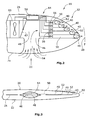
- Fig. 2 illustrates the tip of a rotor blade on a larger scale for depicting the basic constructional features of the pressurized air generating means according to one embodiment of the invention,
- Fig. 3 illustrates a view in the direction of the leading edge of the rotor blade at its tip,
- Fig. 4 illustrates a cross sectional view of a rotor blade of a wind energy turbine without the provision of air outlet openings as suggested for various embodiments of the invention, and
- Fig. 5 illustrates the cross sectional view of a rotor blade of a wind energy turbine comprising air outlet openings for shifting the transition from laminar to turbulent flow towards the leading edge of the blade.
- In one embodiment of the invention, at least one outlet opening for discharging pressurized air is arranged in at least one of opposite upper and lower faces and/or the trailing edge of the blade along which the upper and lower faces of the blade are connected, such as along the leading edge of the blade. The pressurized air is generated by means for generating pressurized air. This means can be operable as an active or passive means generating the pressurized air with the aid of a fan or the like or by receiving air of an air stream which the blade is subjected to during operation and releasing this air as pressurized air via the at least one outlet opening. In one embodiment, the means for generating pressurized air can be designed both as passive and active means.
- The at least one outlet opening is, in one embodiment, arranged e.g. at the tip of a rotor blade in that face thereof which is subjected to suction of the air flowing along the face. Around the tip there is an aerodynamic shortcut between the suction side and the pressure side around the blade. This short cut together with the rotation of the rotor of the wind energy turbine results in the creation of a three dimensional vorticity flow which in turn reduces the aerodynamic lift acting on the tip of the blade. In that pressurized air is ejected towards the tip, generation of vorticities around the tip are prevented and shifted away from the tip so that the aerodynamic performance of the tip increases. The same is true for the root of a blade of a wind energy turbine which also generates three-dimensional vorticities. In addition, arranging the at least one outlet opening or a plurality of outlet openings on the upper end or faces of the blade while ejecting the pressurized air towards the trailing edge of the blade results in shifting the separation line between laminar and turbulent flow towards the trailing edge which in turn results in a more effective use of the surface of the blade for aerodynamic purposes.
- Accordingly, one aspect of the invention relates to the distribution and direction of air jets along the surface of the blade towards the area of the aerodynamic boundary layer around the blade in which areas vorticities and/or turbulences are created so that the percentage of the overall surface size of the blade which can be used for aerodynamic purposes is increased resulting in a more efficient aerodynamic performance of the rotor blade.
- In one embodiment of the present invention, the pressurized air generating means comprises at least one air intake opening arranged at the leading edge of the blade or at another location of the blade or rotor. The air intake opening is in fluid connection with the at least one air outlet opening. As an alternative, the pressurized air generating means includes multiple air intake openings arranged at the leading edge and in fluid connection with the at least one air outlet opening or a plurality of air outlet openings of the blade. The fluid connection between the air intake opening and each of the air outlet openings can be realized by one or a plurality of fluid conduits. To improve the air intake performance of the at least one air intake opening, the pressurized air generating means may also include a collector realized e.g. as a narrowing channel which provides a Venturi effect acting on the intaken air for providing pressure thereto.
- Further, control means such as flow valves, flaps, flow registers, flow diaphragms, flexible elastic conduit or the like are provided for controlling the specific flow rate and specific relative pressure of pressurized air exiting the air outlet opening or outlet openings. Also with the aid of this control means it is possible to selectively shut individual ones of the air outlet openings which can be advantageous depending on the air stream flowing around the blade.
- In another aspect of the present invention, the pressurized air generating means includes a fan for blowing pressurized air out of the at least one air outlet opening. This fan can intake air via an air inlet opening arranged at the leading edge of the blade or at another location of the blade or rotor. In another aspect, the fan is provided as an element of the pressurized air generating means in addition to the passive pressurized air generating means described before. An outlet of the fan can be opened or shut selectively in order to add pressurized air generated by the fan to the flow of pressurized air created from the air inlet opening of the passive pressurized air generating means.
- Further, the pressurized air exits at least through one air outlet opening, which can feature at least one termination or at least one nozzle-like shape in order to introduce specific air outlet opening jet expansion shape(s) or a specific amount of jet vorticity(ies) in specific vorticity direction(s).
- As described above, various aspects of the present invention are applicable to wind energy turbines from both the action and reaction type i.e. to wind energy turbines having a horizontal or vertical rotation axis. More specifically, Fig. 1 illustrates the overall construction of a
wind energy turbine 10 provided with rotor blades designed according to one embodiment. Thewind energy turbine 10 includes a rotor 12 having ahub 14 from which threerotor blades 16 extend radially. The number of rotor blades, in alternative embodiments, can be more or less than three. Rotor 12 is arranged on a nacelle (not shown) ofwind energy turbine 10 which nacelle is supported by atower 18. The nacelle is capable of rotating around a vertical axis while rotor 12 rotates around a horizontal axis. Accordingly,wind energy turbine 10 of Fig. 1 is of the action type. However, the invention is also applicable for rotors of a reaction type wind energy turbine. - Each
rotor blade 10 includes anupper face 20 and an opposite lower face 22 (not shown in Fig. 1 but depicted in Figs. 3 to 5), a leadingedge 24 and an oppositetrailing edge 26 with respect to the direction ofrotation 28 of rotor 12. Eachrotor blade 16 further comprises aroot 30 by whichblade 16 is connected tohub 14, and atip 32 at the radial and ofblade 16. As can be seen from Fig. 1,diverse groups exit openings upper surface 20 of eachblade 16. In an alternative embodiment,blades 16 include more or less than three groups and each group includes more or less than the number of openings depicted in Fig.. In an further embodiment,groups openings - The arrangement of
air outlet openings 40 ofgroup 34 attip 32 ofblade 16 is shown in more detail in Figs. 2 and 3. As can be seen from Fig. 3, attip 32 ofblade 16 there is provided anair intake opening 46 arranged in leadingedge 24 ofblade 16. However, it is to be noted that thisair intake opening 46 can also be arranged within a different portion of leadingedge 24.Air intake opening 46 is in fluid communication with each ofair outlet openings 40 which in Fig. 2 is shown bychannel 48 from which individual fluid conduits extend which lead to individualair outlet openings 40. As an alternative, allair outlet openings 40 can be arranged within one common air channel. As can be seen in particular in Fig. 3,air outlet openings 40 are directed towardstip 32 ofblade 16. During operation of rotor 12, air enterstip 32 throughair intake opening 46 and is guided throughfluid conduits 50 and outair outlet openings 40 as shown byarrows 52 of Fig. 3. Theindividual air streams 52 prevent the creation of a vortex aroundtip 32 ofblade 16 so that the air stream along upper andlower faces tip 32 is more laminar and, accordingly, can be effectively used for the aerodynamic lift. - In one embodiment, the air intake performance and pressurized generation of the air taken in through the openings is improved by arranging a Venturi
collector 54 at air intake opening 46. By this narrowing channel construction the air is forced intochannel 48, providing improved pressurization of the air. - In one embodiment, individual air outlet openings are selectively shut and opened. Accordingly, as shown in Fig. 2,
several valves 56 are arranged associated to each ofair outlet openings 40.Valves 56 are controlled, in one embodiment, by means of acontrol unit 58. - In addition,
rotor blade 16 includes, in one embodiment, afan 60 arranged at one of withinrotor blade 16, withinhub 14, or at any other location within or outsidewind energy turbine 10 for generating an active air stream directed towardsair outlet openings 40.Fan 60, as well as a closing or openingflap 62 is controlled by a control unit which in the embodiment of Fig. 2 also controlsvalves 56. Of course it is to be noted that the pressurized air generating means 64 provided byair intake opening 56 andair outlet openings 40 together withchannel 48 andfluid conduits 50 are also operative withoutfan 60. - The internal fluid communication system for discharging pressurized air out of the
air outlet openings 40 as shown in Figures 2 and 3 relates to a combination of active and passive systems. A fluid communication system of the passive type comprises a fluid communication betweenintake opening 46 andoutlet openings 40 without a fan or the like while an active type fluid communication system includes a motorized fan in fluid communication withair intake opening 46 andoutlet openings 40. Irrespective of the active or passive type fluid communication system,outlet openings 40 are designed, in one embodiment, as nozzles to eject the pressurized air as air jets. - By means of the
pressurized air jets 52 ejected from theair outlet openings 40 alongupper face 20 ofblade 16 and perpendicular to the air stream to whichrotor blade 16 is subjected reduces and/or prevents generation of vorticities attip 32 ofrotor blade 16. By means ofair outlet openings 42 of Fig. 1 which are arranged inupper face 20 closer to trailingedge 26 than to leadingedge 24 it is possible to shift the transition from laminar to turbulent flow alongblade 16 towards its trailingedge 26. This phenomenon is depicted in Figs. 4 and 5. The normal situation withoutair outlet openings 46 is shown in Fig. 4.Air stream 66 flows as a laminar flow alongupper face 20 andlower face 22 up totransitions air outlet openings 42,pressurized air jets 72 are ejected alongupper face 20 and towards trailingedge 28 so thattransition 68 atupper face 20 is shifted backwards towards trailingedge 26 resulting in an increase of the percentage of the surface area aerodynamically used for lift off. - The air which is ejected through
air outlet openings 42 can be taken in by means of additional air intake openings (not shown) arranged in leadingedge 24 of theblade 16 and/or by air generated actively by means offan 60 or another fan provided atwind energy turbine 10. -
Air outlet openings 44 atroot 30 ofblade 16 are operative similar to the shift of the transition as shown in Figs. 4 and 5 by the provision ofair outlet openings 42. - While the invention has been described in terms of various specific embodiments, those skilled in the art will recognize that the invention can be practiced with modification within the spirit and scope of the claims.
-
10 wind energy turbine 12 rotor 14 hub 16 blade 18 tower 20 upper face 22 lower face 24 leading edge 26 trailing edge 28 direction of rotation 30 root 32 tip 34 groups 36 groups 38 groups 40 air outlet openings 42 air outlet openings 44 air outlet openings 46 air intake opening 48 channel 50 fluid conduits 52 air jets 54 Venturi collector 56 valves 58 control unit 60 fan 62 closing or opening flap 64 air generating means 66 air stream 68 transitions 70 transitions 72 air jets
Claims (10)
- A blade (16) for a rotor (12) of a wind energy turbine (10), said blade comprising:opposite upper and lower faces (20, 22);opposite leading and trailing edges (24, 26) connecting said upper and lower faces;means (64) for generating pressurized air; andat least one air outlet opening (40) in fluid communication with said pressurized air generation means and arranged on at least one of said upper face, said lower face and said trailing edge for discharging the pressurized air into the air around at least one of said upper and lower faces and said leading and trailing edges.
- The blade (16) according to Claim 1 further comprising a root (30) and a tip (32) arranged at ends of said leading and trailing edges (24, 26), said at least one air outlet opening (40) arranged on at least one of said upper and lower faces (20, 22) at at least one of said root and said tip.
- The blade (16) according to Claim 1 or Claim 2 wherein said pressurized air generating means (64) comprises at least one air intake opening (46) arranged at said leading edge (24) and in fluid communication with said at least one air outlet opening(40).
- The blade (16) according to Claim 3 wherein multiple air outlet openings (40) are provided, each said outlet opening in fluid communication with said at least one air intake opening (46) by means of at least one fluid conduit (50).
- The blade (16) according to Claim 3 or Claim 4 wherein said pressurized generating means (64) further comprises a collector arranged at said at least one air intake opening (46).
- The blade (16) according to any preceding Claim, further comprising one or more valves (56) operable to control said at least one air outlet opening (40).
- The blade (16) according to any preceding Claim wherein said pressurized air generating means (64) comprises a fan (60) for blowing pressurized air out of said at least one air outlet opening (40).
- The blade (16) according to Claim 7 wherein an outlet of said fan (60) is in fluid communication with said at least one air outlet opening (40) and wherein an inlet opening of said fan is provided for intaking air by said fan.
- The blade (16) according to Claim 7 or Claim 8 wherein said inlet opening for said fan (60) is in fluid communication with at least oneP of said at least one air intake opening (46) of the pressurized air generation means (64).
- The blade (16) according to Claim 8 or Claim 9 wherein an outlet of said fan (60) is in fluid communication with said at least one air outlet opening (40) and wherein an inlet opening of said fan is provided for intaking air by said fan.
Applications Claiming Priority (1)
| Application Number | Priority Date | Filing Date | Title |
|---|---|---|---|
| US11/259,899 US7354247B2 (en) | 2005-10-27 | 2005-10-27 | Blade for a rotor of a wind energy turbine |
Publications (2)
| Publication Number | Publication Date |
|---|---|
| EP1780408A1 true EP1780408A1 (en) | 2007-05-02 |
| EP1780408B1 EP1780408B1 (en) | 2015-05-06 |
Family
ID=37684954
Family Applications (1)
| Application Number | Title | Priority Date | Filing Date |
|---|---|---|---|
| EP20060255505 Not-in-force EP1780408B1 (en) | 2005-10-27 | 2006-10-26 | Blade for a rotor of a wind energy turbine |
Country Status (6)
| Country | Link |
|---|---|
| US (1) | US7354247B2 (en) |
| EP (1) | EP1780408B1 (en) |
| CN (1) | CN1955459B (en) |
| BR (1) | BRPI0604707A (en) |
| DK (1) | DK1780408T3 (en) |
| MX (1) | MXPA06012371A (en) |
Cited By (9)
| Publication number | Priority date | Publication date | Assignee | Title |
|---|---|---|---|---|
| NL2000821C2 (en) * | 2007-08-17 | 2009-02-18 | Stichting Energie | Wind turbine and rotor blade. |
| WO2009025548A1 (en) * | 2007-08-17 | 2009-02-26 | Stichting Energieonderzoek Centrum Nederland | Wind turbine and rotor blade with reduced load fluctuations |
| WO2011053119A1 (en) * | 2009-10-28 | 2011-05-05 | Actiflow B.V. | Wind turbine blade |
| CN102052248A (en) * | 2009-11-05 | 2011-05-11 | 通用电气公司 | Systems and method for operating an active flow control system for a wind turbine |
| EP2497944A1 (en) * | 2011-01-04 | 2012-09-12 | General Electric Company | System and method of manipulating a boundary layer across a rotor blade of a wind turbine |
| WO2013076008A1 (en) * | 2011-11-23 | 2013-05-30 | Lm Wind Power A/S | A wind turbine blade |
| EP2333317A3 (en) * | 2009-12-10 | 2014-01-15 | General Electric Company | Systems and methods for assembling an air distribution system for use in a rotor blade of a wind turbine |
| EP2320083A3 (en) * | 2009-11-05 | 2014-03-26 | General Electric Company | Systems and method for operating a wind turbine having active flow control |
| EP3034871A1 (en) * | 2014-12-17 | 2016-06-22 | Siemens Aktiengesellschaft | Rotor blade with an opening at the tip section |
Families Citing this family (54)
| Publication number | Priority date | Publication date | Assignee | Title |
|---|---|---|---|---|
| US20070231151A1 (en) * | 2005-10-10 | 2007-10-04 | General Electric Company | Active flow control for wind turbine blades |
| EP2122164B1 (en) * | 2007-01-05 | 2016-03-23 | LM WP Patent Holding A/S | Wind turbine blade with lift-regulating means in form of slots or holes |
| US7909575B2 (en) * | 2007-06-25 | 2011-03-22 | General Electric Company | Power loss reduction in turbulent wind for a wind turbine using localized sensing and control |
| US20100068431A1 (en) * | 2008-09-17 | 2010-03-18 | Vishal Bansal | Article and method for forming an article |
| US9239039B2 (en) * | 2008-10-27 | 2016-01-19 | General Electric Company | Active circulation control of aerodynamic structures |
| US20120045329A1 (en) * | 2009-02-10 | 2012-02-23 | West Virginia University | Method for circulation controlled vertical axis and turbines |
| WO2010093621A1 (en) * | 2009-02-10 | 2010-08-19 | West Virginia University | Method for circulation controlled vertical axis wind turbines |
| US7942640B2 (en) * | 2009-03-19 | 2011-05-17 | General Electric Company | Method and apparatus for use in protecting wind turbine blades from lightning damage |
| CN101886612A (en) * | 2009-05-11 | 2010-11-17 | 上海神飞能源科技有限公司 | Method for regulating air dynamic behaviour of blades of wind motor |
| US8444383B1 (en) * | 2009-05-29 | 2013-05-21 | Glenn James Baker | Wind turbine with internal ram air turbine |
| GB0914591D0 (en) * | 2009-08-21 | 2009-09-30 | Rolls Royce Plc | Fluidfoil tip vortex disruption |
| US8425190B2 (en) * | 2009-10-26 | 2013-04-23 | United Ship Design And Development Center | Pressure relief device |
| US20110103950A1 (en) * | 2009-11-04 | 2011-05-05 | General Electric Company | System and method for providing a controlled flow of fluid to or from a wind turbine blade surface |
| US8221075B2 (en) * | 2009-11-05 | 2012-07-17 | General Electric Company | Systems and method for operating a wind turbine having active flow control |
| US8376704B2 (en) * | 2009-11-05 | 2013-02-19 | General Electric Company | Systems and method of assembling an air distribution system for use in a rotor blade of a wind turbine |
| US8092172B2 (en) | 2009-11-05 | 2012-01-10 | General Electric Company | Method for operating a wind turbine with reduced blade fouling |
| US7931445B2 (en) * | 2009-11-05 | 2011-04-26 | General Electric Company | Apparatus and method for cleaning an active flow control (AFC) system of a wind turbine |
| US7883313B2 (en) * | 2009-11-05 | 2011-02-08 | General Electric Company | Active flow control system for wind turbine |
| US20110211950A1 (en) * | 2009-11-12 | 2011-09-01 | Remco International, Inc. | Method of dynamic energy-saving superconductive propeller interaction with a fluid medium |
| MX341495B (en) | 2010-01-14 | 2016-08-23 | Neptco Inc * | WIND TURBINE ROTOR BLADE COMPONENTS AND METHODS FOR THE MANUFACTURE OF THE SAME. |
| US10137542B2 (en) | 2010-01-14 | 2018-11-27 | Senvion Gmbh | Wind turbine rotor blade components and machine for making same |
| CN102884311B (en) * | 2010-02-16 | 2015-11-25 | 技术研究及发展基金有限公司 | Flow Control for Vertical Axis Wind Turbines (VAWT) |
| US20110206531A1 (en) * | 2010-02-22 | 2011-08-25 | Desktop Aeronautics | Efficient low-cost wind energy using passive circulation control |
| US8449255B2 (en) * | 2010-03-21 | 2013-05-28 | Btpatent Llc | Wind turbine blade system with air passageway |
| US20110229329A1 (en) * | 2010-03-22 | 2011-09-22 | Occhipinti Anthony C | Propeller augmentation |
| US8016560B2 (en) * | 2010-09-17 | 2011-09-13 | General Electric Company | Wind turbine rotor blade with actuatable airfoil passages |
| US20120082562A1 (en) * | 2010-10-05 | 2012-04-05 | Kotler Andrey | Wind turbine |
| US10138870B2 (en) * | 2010-12-09 | 2018-11-27 | Ramot At Tel-Aviv University Ltd. | Method and system of providing fluid flow for a rotor |
| US8267653B2 (en) * | 2010-12-21 | 2012-09-18 | General Electric Company | System and method of operating an active flow control system to manipulate a boundary layer across a rotor blade of a wind turbine |
| US20110211952A1 (en) * | 2011-02-10 | 2011-09-01 | General Electric Company | Rotor blade for wind turbine |
| US9133819B2 (en) | 2011-07-18 | 2015-09-15 | Kohana Technologies Inc. | Turbine blades and systems with forward blowing slots |
| US9090343B2 (en) * | 2011-10-13 | 2015-07-28 | Sikorsky Aircraft Corporation | Rotor blade component cooling |
| JP5594740B2 (en) * | 2011-12-28 | 2014-09-24 | 株式会社日本製鋼所 | Wind power blade and wind power generator |
| CN102619572B (en) * | 2012-03-21 | 2016-06-01 | 朱晓义 | Impeller and adopt the power set of this impeller |
| KR101460188B1 (en) | 2012-12-07 | 2014-11-10 | 전기재 | Windmill wings for generating device and generating device comprising the same |
| PL2998572T3 (en) * | 2014-09-22 | 2017-02-28 | Best Blades Gmbh | Wind turbine rotor propeller blade |
| CN104747241A (en) * | 2015-01-23 | 2015-07-01 | 朱晓义 | Pressure device and turbine engine |
| WO2016078537A1 (en) * | 2014-11-17 | 2016-05-26 | 朱晓义 | Power device and automobile engine |
| US20160177922A1 (en) * | 2014-12-22 | 2016-06-23 | Siemens Aktiengesellschaft | Trailing edge jets on wind turbine blade for noise reduction |
| US10302064B2 (en) * | 2015-07-30 | 2019-05-28 | The Boeing Company | Methods and systems for rotary wing active flow control |
| WO2017048683A1 (en) * | 2015-09-17 | 2017-03-23 | Sikorsky Aircraft Corporation | Stress reducing holes |
| US10240579B2 (en) * | 2016-01-27 | 2019-03-26 | General Electric Company | Apparatus and method for aerodynamic performance enhancement of a wind turbine |
| DE102016123412A1 (en) * | 2016-12-05 | 2018-06-07 | Wobben Properties Gmbh | Rotor blade for a wind turbine and wind turbine |
| US11472536B1 (en) * | 2017-02-06 | 2022-10-18 | Khaled Abdullah Alhussan | System to control flow separation over an airfoil |
| US10371121B1 (en) * | 2017-02-21 | 2019-08-06 | Khaled Abdullah Alhussan | Wind turbine blade with a passive porous medium for flow separation control |
| DE102017112742A1 (en) * | 2017-06-09 | 2018-12-13 | Wobben Properties Gmbh | Rotor blade for a wind turbine and wind turbine |
| US10683076B2 (en) | 2017-10-31 | 2020-06-16 | Coflow Jet, LLC | Fluid systems that include a co-flow jet |
| US11920617B2 (en) | 2019-07-23 | 2024-03-05 | Coflow Jet, LLC | Fluid systems and methods that address flow separation |
| CN111472927A (en) * | 2020-04-09 | 2020-07-31 | 太原科技大学 | Active load reduction large-scale wind driven generator blade |
| WO2021257271A1 (en) | 2020-06-17 | 2021-12-23 | Coflow Jet, LLC | Fluid systems having a variable configuration |
| CN111577531B (en) * | 2020-06-28 | 2024-04-05 | 上海海事大学 | Shark gill type blade drag reduction structure for wind driven generator, blade and manufacturing method |
| WO2022204278A1 (en) | 2021-03-26 | 2022-09-29 | Coflow Jet, LLC | Wind turbine blades and wind turbine systems that include a co-flow jet |
| US12451763B1 (en) | 2021-05-05 | 2025-10-21 | Dennis Grieve | Air flow powered electrical generator |
| CN116733676A (en) * | 2023-06-26 | 2023-09-12 | 北京国能风光能源科技有限公司 | Wind-solar generator based on double-fan advection boosting |
Citations (8)
| Publication number | Priority date | Publication date | Assignee | Title |
|---|---|---|---|---|
| US2408788A (en) * | 1939-06-16 | 1946-10-08 | Ludington Charles Townsend | Airfoil |
| GB596367A (en) * | 1944-05-23 | 1948-01-02 | Roger Wolcott Griswold O | Improvements in airfoils |
| US3005496A (en) * | 1959-08-24 | 1961-10-24 | Hiller Aircraft Corp | Airfoil boundary layer control means |
| US5791601A (en) * | 1995-08-22 | 1998-08-11 | Dancila; D. Stefan | Apparatus and method for aerodynamic blowing control using smart materials |
| US5938404A (en) * | 1997-06-05 | 1999-08-17 | Mcdonnell Douglas Helicopter Company | Oscillating air jets on aerodynamic surfaces |
| WO2000050778A1 (en) * | 1999-02-25 | 2000-08-31 | United Technologies Corporation | Vibration-driven acoustic jet controlling boundary layer separation |
| DE10126814A1 (en) * | 2001-06-01 | 2003-03-20 | Sen Alexander Faller | Windmill rotor has hollow blades through which air flows from hub to tip |
| US20060088421A1 (en) * | 2002-12-30 | 2006-04-27 | Shchukin Iliya L | Method for increasing operating efficiency of the rotor blade of an aerogenerator (variants) |
Family Cites Families (18)
| Publication number | Priority date | Publication date | Assignee | Title |
|---|---|---|---|---|
| US3480234A (en) * | 1967-08-18 | 1969-11-25 | Lockheed Aircraft Corp | Method and apparatus for modifying airfoil fluid flow |
| US3692259A (en) * | 1970-06-26 | 1972-09-19 | Shao Wen Yuan | Wing-tip vortices control |
| US4697769A (en) | 1984-04-23 | 1987-10-06 | Flow Industries, Inc. | Method and apparatus for controlling bound vortices in the vicinity of lifting surfaces |
| GB8713097D0 (en) | 1987-06-04 | 1987-07-08 | Adkins R C | Aerofoil/hydrofoil |
| US5297764A (en) * | 1993-03-15 | 1994-03-29 | Haney William R | Air foil providing vortex attenuation |
| US5632599A (en) | 1996-06-03 | 1997-05-27 | Prime Energy Corporation | Turbine with circumferential support and stationary pressure release means |
| IL121164A (en) * | 1997-06-26 | 2002-03-10 | Univ Ramot | Airfoil with dynamic stall control by oscillatory forcing |
| US6203269B1 (en) | 1999-02-25 | 2001-03-20 | United Technologies Corporation | Centrifugal air flow control |
| US6412731B1 (en) | 1999-12-23 | 2002-07-02 | Edwin Zenith Gabriel | Simplified buoyancy system for avoiding aircraft crashes |
| FR2814204B1 (en) * | 2000-09-20 | 2003-02-07 | Georges Boulisset | REACTIVE HOLLOW BLADE FOR WIND TURBINE |
| EP1436506A4 (en) | 2001-09-19 | 2004-11-03 | Keun-Suk Jang | Windmill blade and apparatus for generating power using the blade |
| HRPK20010755B1 (en) * | 2001-10-18 | 2004-10-31 | Dragutin Boueatlic | Wing able to enhance lift by internal air flow |
| US20030201367A1 (en) | 2002-04-24 | 2003-10-30 | Saiz Manuel Munoz | Process for the recovery of the energy from the air in pressurised areas of aircraft |
| US6849964B2 (en) | 2002-09-13 | 2005-02-01 | Axis Usa, Inc. | Wind powered energy generating machine |
| FR2846382B1 (en) * | 2003-02-12 | 2006-01-13 | Georges Boulisset | DEVICE FOR IMPROVING THE PERFORMANCE OF WINDMILL BLADES |
| US6887031B1 (en) | 2004-03-16 | 2005-05-03 | Angus J. Tocher | Habitat friendly, pressure conversion, wind energy extraction |
| US7134631B2 (en) | 2004-06-10 | 2006-11-14 | Loth John L | Vorticity cancellation at trailing edge for induced drag elimination |
| US20070092680A1 (en) | 2005-10-26 | 2007-04-26 | Sterling Chaffins | Laser writable media substrate, and systems and methods of laser writing |
-
2005
- 2005-10-27 US US11/259,899 patent/US7354247B2/en not_active Expired - Lifetime
-
2006
- 2006-10-26 BR BRPI0604707-6A patent/BRPI0604707A/en not_active IP Right Cessation
- 2006-10-26 MX MXPA06012371A patent/MXPA06012371A/en active IP Right Grant
- 2006-10-26 EP EP20060255505 patent/EP1780408B1/en not_active Not-in-force
- 2006-10-26 DK DK06255505.7T patent/DK1780408T3/en active
- 2006-10-27 CN CN2006101495350A patent/CN1955459B/en not_active Expired - Fee Related
Patent Citations (8)
| Publication number | Priority date | Publication date | Assignee | Title |
|---|---|---|---|---|
| US2408788A (en) * | 1939-06-16 | 1946-10-08 | Ludington Charles Townsend | Airfoil |
| GB596367A (en) * | 1944-05-23 | 1948-01-02 | Roger Wolcott Griswold O | Improvements in airfoils |
| US3005496A (en) * | 1959-08-24 | 1961-10-24 | Hiller Aircraft Corp | Airfoil boundary layer control means |
| US5791601A (en) * | 1995-08-22 | 1998-08-11 | Dancila; D. Stefan | Apparatus and method for aerodynamic blowing control using smart materials |
| US5938404A (en) * | 1997-06-05 | 1999-08-17 | Mcdonnell Douglas Helicopter Company | Oscillating air jets on aerodynamic surfaces |
| WO2000050778A1 (en) * | 1999-02-25 | 2000-08-31 | United Technologies Corporation | Vibration-driven acoustic jet controlling boundary layer separation |
| DE10126814A1 (en) * | 2001-06-01 | 2003-03-20 | Sen Alexander Faller | Windmill rotor has hollow blades through which air flows from hub to tip |
| US20060088421A1 (en) * | 2002-12-30 | 2006-04-27 | Shchukin Iliya L | Method for increasing operating efficiency of the rotor blade of an aerogenerator (variants) |
Cited By (14)
| Publication number | Priority date | Publication date | Assignee | Title |
|---|---|---|---|---|
| CN101790637B (en) * | 2007-08-17 | 2012-06-13 | 荷兰能源研究中心基金会 | Wind turbine and rotor blade with reduced load fluctuations |
| WO2009025549A1 (en) * | 2007-08-17 | 2009-02-26 | Stichting Energieonderzoek Centrum Nederland | Wind turbine and rotor blade with reduced trailing edge noise |
| WO2009025548A1 (en) * | 2007-08-17 | 2009-02-26 | Stichting Energieonderzoek Centrum Nederland | Wind turbine and rotor blade with reduced load fluctuations |
| NL2000821C2 (en) * | 2007-08-17 | 2009-02-18 | Stichting Energie | Wind turbine and rotor blade. |
| WO2011053119A1 (en) * | 2009-10-28 | 2011-05-05 | Actiflow B.V. | Wind turbine blade |
| EP2320079A3 (en) * | 2009-11-05 | 2014-02-26 | General Electric Company | Systems and method for operating an active flow control system for a wind turbine |
| CN102052248A (en) * | 2009-11-05 | 2011-05-11 | 通用电气公司 | Systems and method for operating an active flow control system for a wind turbine |
| EP2320083A3 (en) * | 2009-11-05 | 2014-03-26 | General Electric Company | Systems and method for operating a wind turbine having active flow control |
| EP2333317A3 (en) * | 2009-12-10 | 2014-01-15 | General Electric Company | Systems and methods for assembling an air distribution system for use in a rotor blade of a wind turbine |
| EP2497944A1 (en) * | 2011-01-04 | 2012-09-12 | General Electric Company | System and method of manipulating a boundary layer across a rotor blade of a wind turbine |
| WO2013076008A1 (en) * | 2011-11-23 | 2013-05-30 | Lm Wind Power A/S | A wind turbine blade |
| CN104220746A (en) * | 2011-11-23 | 2014-12-17 | Lmwp专利控股有限公司 | A wind turbine blade |
| CN104220746B (en) * | 2011-11-23 | 2017-12-08 | Lm Wp 专利控股有限公司 | Wind turbine blade |
| EP3034871A1 (en) * | 2014-12-17 | 2016-06-22 | Siemens Aktiengesellschaft | Rotor blade with an opening at the tip section |
Also Published As
| Publication number | Publication date |
|---|---|
| EP1780408B1 (en) | 2015-05-06 |
| BRPI0604707A (en) | 2007-08-28 |
| CN1955459A (en) | 2007-05-02 |
| DK1780408T3 (en) | 2015-06-29 |
| CN1955459B (en) | 2011-08-24 |
| US7354247B2 (en) | 2008-04-08 |
| MXPA06012371A (en) | 2007-04-26 |
| US20070098552A1 (en) | 2007-05-03 |
Similar Documents
| Publication | Publication Date | Title |
|---|---|---|
| EP1780408B1 (en) | Blade for a rotor of a wind energy turbine | |
| US7018166B2 (en) | Ducted wind turbine | |
| EP1553261B1 (en) | Turbine airfoil with trailing edge teardrop array | |
| US20110103950A1 (en) | System and method for providing a controlled flow of fluid to or from a wind turbine blade surface | |
| CA2658914C (en) | Impulse turbine for use in bi-directional flows | |
| CN102094765B (en) | System and method for assembling an air distribution system for use in a rotor blade of a wind turbine | |
| JPS60500302A (en) | wind turbine equipment | |
| US20150300183A1 (en) | Fluid Turbine With Turbine Shroud And Ejector Shroud Coupled With High Thrust-Coefficient Rotor | |
| CN110036196A (en) | Rotor blades and wind energy installations for wind energy installations | |
| CN111075760A (en) | Fluid wing | |
| US12352235B2 (en) | Wind turbine blades and wind turbine systems that include a co-flow jet | |
| JP7346165B2 (en) | Crossflow fan, lift generator equipped with the same, and aircraft equipped with the same | |
| CA3063634A1 (en) | Rotor blade for a wind turbine and wind turbine | |
| WO2019105517A1 (en) | Wind turbine blade | |
| CN117605707A (en) | A centrifugal fan impeller with a vortex generator structure | |
| AU2013200683B2 (en) | Impulse turbine for use in bi-directional flows | |
| EP0974515A2 (en) | Aircraft airconditioning energy recovery device | |
| EP4286683B1 (en) | Trailing edge noise reduction using an airfoil with an internal bypass channel | |
| KR102694590B1 (en) | Blade of horizontal axis wind turbine | |
| US20170138261A1 (en) | Aircraft turbine engine air intake duct |
Legal Events
| Date | Code | Title | Description |
|---|---|---|---|
| PUAI | Public reference made under article 153(3) epc to a published international application that has entered the european phase |
Free format text: ORIGINAL CODE: 0009012 |
|
| AK | Designated contracting states |
Kind code of ref document: A1 Designated state(s): AT BE BG CH CY CZ DE DK EE ES FI FR GB GR HU IE IS IT LI LT LU LV MC NL PL PT RO SE SI SK TR |
|
| AX | Request for extension of the european patent |
Extension state: AL BA HR MK YU |
|
| 17P | Request for examination filed |
Effective date: 20071102 |
|
| 17Q | First examination report despatched |
Effective date: 20071213 |
|
| AKX | Designation fees paid |
Designated state(s): DE DK ES GB NL |
|
| GRAP | Despatch of communication of intention to grant a patent |
Free format text: ORIGINAL CODE: EPIDOSNIGR1 |
|
| INTG | Intention to grant announced |
Effective date: 20150224 |
|
| GRAS | Grant fee paid |
Free format text: ORIGINAL CODE: EPIDOSNIGR3 |
|
| GRAA | (expected) grant |
Free format text: ORIGINAL CODE: 0009210 |
|
| AK | Designated contracting states |
Kind code of ref document: B1 Designated state(s): DE DK ES GB NL |
|
| REG | Reference to a national code |
Ref country code: GB Ref legal event code: FG4D |
|
| REG | Reference to a national code |
Ref country code: DE Ref legal event code: R096 Ref document number: 602006045349 Country of ref document: DE Effective date: 20150618 |
|
| REG | Reference to a national code |
Ref country code: DK Ref legal event code: T3 Effective date: 20150625 |
|
| REG | Reference to a national code |
Ref country code: NL Ref legal event code: MP Effective date: 20150506 |
|
| PG25 | Lapsed in a contracting state [announced via postgrant information from national office to epo] |
Ref country code: ES Free format text: LAPSE BECAUSE OF FAILURE TO SUBMIT A TRANSLATION OF THE DESCRIPTION OR TO PAY THE FEE WITHIN THE PRESCRIBED TIME-LIMIT Effective date: 20150506 |
|
| REG | Reference to a national code |
Ref country code: DE Ref legal event code: R097 Ref document number: 602006045349 Country of ref document: DE |
|
| PLBE | No opposition filed within time limit |
Free format text: ORIGINAL CODE: 0009261 |
|
| STAA | Information on the status of an ep patent application or granted ep patent |
Free format text: STATUS: NO OPPOSITION FILED WITHIN TIME LIMIT |
|
| 26N | No opposition filed |
Effective date: 20160209 |
|
| GBPC | Gb: european patent ceased through non-payment of renewal fee |
Effective date: 20151026 |
|
| PG25 | Lapsed in a contracting state [announced via postgrant information from national office to epo] |
Ref country code: GB Free format text: LAPSE BECAUSE OF NON-PAYMENT OF DUE FEES Effective date: 20151026 |
|
| PG25 | Lapsed in a contracting state [announced via postgrant information from national office to epo] |
Ref country code: NL Free format text: LAPSE BECAUSE OF FAILURE TO SUBMIT A TRANSLATION OF THE DESCRIPTION OR TO PAY THE FEE WITHIN THE PRESCRIBED TIME-LIMIT Effective date: 20150506 |
|
| PGFP | Annual fee paid to national office [announced via postgrant information from national office to epo] |
Ref country code: DK Payment date: 20210923 Year of fee payment: 16 |
|
| PGFP | Annual fee paid to national office [announced via postgrant information from national office to epo] |
Ref country code: DE Payment date: 20210921 Year of fee payment: 16 |
|
| REG | Reference to a national code |
Ref country code: DE Ref legal event code: R119 Ref document number: 602006045349 Country of ref document: DE |
|
| REG | Reference to a national code |
Ref country code: DK Ref legal event code: EBP Effective date: 20221031 |
|
| P01 | Opt-out of the competence of the unified patent court (upc) registered |
Effective date: 20230522 |
|
| PG25 | Lapsed in a contracting state [announced via postgrant information from national office to epo] |
Ref country code: DE Free format text: LAPSE BECAUSE OF NON-PAYMENT OF DUE FEES Effective date: 20230503 |
|
| PG25 | Lapsed in a contracting state [announced via postgrant information from national office to epo] |
Ref country code: DK Free format text: LAPSE BECAUSE OF NON-PAYMENT OF DUE FEES Effective date: 20221031 |