EP1780389A2 - Methods and apparatus for operating gas turbine engines - Google Patents
Methods and apparatus for operating gas turbine engines Download PDFInfo
- Publication number
- EP1780389A2 EP1780389A2 EP06255562A EP06255562A EP1780389A2 EP 1780389 A2 EP1780389 A2 EP 1780389A2 EP 06255562 A EP06255562 A EP 06255562A EP 06255562 A EP06255562 A EP 06255562A EP 1780389 A2 EP1780389 A2 EP 1780389A2
- Authority
- EP
- European Patent Office
- Prior art keywords
- fuel
- working fluid
- gas turbine
- combustor
- turbine engine
- Prior art date
- Legal status (The legal status is an assumption and is not a legal conclusion. Google has not performed a legal analysis and makes no representation as to the accuracy of the status listed.)
- Granted
Links
Images


Classifications
-
- F—MECHANICAL ENGINEERING; LIGHTING; HEATING; WEAPONS; BLASTING
- F02—COMBUSTION ENGINES; HOT-GAS OR COMBUSTION-PRODUCT ENGINE PLANTS
- F02C—GAS-TURBINE PLANTS; AIR INTAKES FOR JET-PROPULSION PLANTS; CONTROLLING FUEL SUPPLY IN AIR-BREATHING JET-PROPULSION PLANTS
- F02C7/00—Features, components parts, details or accessories, not provided for in, or of interest apart form groups F02C1/00 - F02C6/00; Air intakes for jet-propulsion plants
- F02C7/22—Fuel supply systems
- F02C7/224—Heating fuel before feeding to the burner
-
- F—MECHANICAL ENGINEERING; LIGHTING; HEATING; WEAPONS; BLASTING
- F02—COMBUSTION ENGINES; HOT-GAS OR COMBUSTION-PRODUCT ENGINE PLANTS
- F02C—GAS-TURBINE PLANTS; AIR INTAKES FOR JET-PROPULSION PLANTS; CONTROLLING FUEL SUPPLY IN AIR-BREATHING JET-PROPULSION PLANTS
- F02C3/00—Gas-turbine plants characterised by the use of combustion products as the working fluid
- F02C3/20—Gas-turbine plants characterised by the use of combustion products as the working fluid using a special fuel, oxidant, or dilution fluid to generate the combustion products
- F02C3/30—Adding water, steam or other fluids for influencing combustion, e.g. to obtain cleaner exhaust gases
- F02C3/305—Increasing the power, speed, torque or efficiency of a gas turbine or the thrust of a turbojet engine by injecting or adding water, steam or other fluids
-
- F—MECHANICAL ENGINEERING; LIGHTING; HEATING; WEAPONS; BLASTING
- F05—INDEXING SCHEMES RELATING TO ENGINES OR PUMPS IN VARIOUS SUBCLASSES OF CLASSES F01-F04
- F05D—INDEXING SCHEME FOR ASPECTS RELATING TO NON-POSITIVE-DISPLACEMENT MACHINES OR ENGINES, GAS-TURBINES OR JET-PROPULSION PLANTS
- F05D2270/00—Control
- F05D2270/01—Purpose of the control system
- F05D2270/08—Purpose of the control system to produce clean exhaust gases
- F05D2270/082—Purpose of the control system to produce clean exhaust gases with as little NOx as possible
-
- Y—GENERAL TAGGING OF NEW TECHNOLOGICAL DEVELOPMENTS; GENERAL TAGGING OF CROSS-SECTIONAL TECHNOLOGIES SPANNING OVER SEVERAL SECTIONS OF THE IPC; TECHNICAL SUBJECTS COVERED BY FORMER USPC CROSS-REFERENCE ART COLLECTIONS [XRACs] AND DIGESTS
- Y02—TECHNOLOGIES OR APPLICATIONS FOR MITIGATION OR ADAPTATION AGAINST CLIMATE CHANGE
- Y02E—REDUCTION OF GREENHOUSE GAS [GHG] EMISSIONS, RELATED TO ENERGY GENERATION, TRANSMISSION OR DISTRIBUTION
- Y02E20/00—Combustion technologies with mitigation potential
- Y02E20/16—Combined cycle power plant [CCPP], or combined cycle gas turbine [CCGT]
Definitions
- This invention relates generally to gas turbine engines, and more specifically to methods and apparatus for operating gas turbine engines.
- Gas turbine engines generally include, in serial flow arrangement, a high-pressure compressor for compressing air flowing through the engine, a combustor in which fuel is mixed with the compressed air and ignited to form a high temperature gas stream, and a high-pressure turbine.
- the high-pressure compressor, combustor and high-pressure turbine are sometimes collectively referred to as the core engine.
- Such gas turbine engines also may include a low-pressure compressor, or booster, for supplying compressed air to the high-pressure compressor.
- EPA Environmental Protection Agency
- At least one known gas turbine engine includes a water injection system that is configured to inject water into the combustor to facilitate reducing nitrous oxide emissions from the gas turbine engine by reducing the flame temperature in the combustor.
- a water injection system configured to inject water into the combustor to facilitate reducing nitrous oxide emissions from the gas turbine engine by reducing the flame temperature in the combustor.
- injecting water into the combustor may also result in a significant decrease in the fuel efficiency of the gas turbine engine.
- a method for operating a gas turbine engine including a compressor, a combustor, and a turbine, coupled together in serial flow arrangement, and a fuel heating system including a heat exchanger and an economizer is provided.
- the method includes channeling fuel through the heat exchanger, channeling a working fluid through the heat exchanger to facilitate regulating the operating temperature of the fuel and the operating temperature of the working fluid, and channeling the fuel and the working fluid into the gas turbine engine combustor to facilitate increasing a fuel efficiency of the gas turbine engine.
- a fuel heating system for a gas turbine engine including at least a combustor and a turbine
- the fuel heating system includes a heat exchanger comprising a fuel circuit having fuel flowing therethrough and a working fluid circuit having a working fluid flowing therethrough to regulate the operating temperature of the fuel flowing through the fuel circuit, the heat exchanger configured to discharge fuel from the fuel circuit into the combustor, and to discharge the working fluid from the working fluid circuit to the combustor to facilitate increasing the fuel efficiency of the gas turbine engine.
- a gas turbine engine assembly in a further aspect, includes a compressor, a combustor downstream from the compressor, a turbine coupled in flow communication with the combustor, and a fuel heating system.
- the fuel heating system includes a heat exchanger comprising a fuel circuit having fuel flowing therethrough and a working fluid circuit having a working fluid flowing therethrough to regulate the operating temperature of the fuel flowing through the fuel circuit, the heat exchanger configured to discharge fuel from the fuel circuit into the combustor, and to discharge the working fluid from the working fluid circuit to the combustor to facilitate increasing the fuel efficiency of the gas turbine engine.
- FIG. 1 is a block diagram of a gas turbine engine assembly 8 including a gas turbine engine 10 and a fuel heating system 50.
- Gas turbine engine 10 includes, in serial flow relationship, a low-pressure compressor or booster 14, a high-pressure compressor 16, a combustor 18, a high-pressure turbine 20, a low-pressure, or intermediate turbine 22, and a power turbine or free turbine 24.
- Low-pressure compressor or booster 14 has an inlet 26 and an outlet 28, and high-pressure compressor 16 includes an inlet 30 and an outlet 32.
- Combustor 18 has an inlet 34 that is substantially coincident with high-pressure compressor outlet 32, and an outlet 36.
- High-pressure turbine 20 is coupled to high-pressure compressor 16 with a first rotor shaft 40
- low-pressure turbine 22 is coupled to low-pressure compressor 14 with a second rotor shaft 42.
- Rotor shafts 40 and 42 are each substantially coaxially aligned with respect to a longitudinal centerline axis 43 of engine 10.
- Engine 10 may be used to drive a load, not shown, which may be coupled to a power turbine shaft 44.
- the load may be coupled to a forward extension, not shown, of rotor shaft 42.
- ambient air drawn into low-pressure compressor inlet 26 is compressed and channeled downstream to high-pressure compressor 16.
- High-pressure compressor 16 further compresses the air and delivers high-pressure air to combustor 18 where it is mixed with fuel, and the mixture is ignited to generate high temperature combustion gases.
- the combustion gases are channeled from combustor 18 to drive turbines 20, 22, and 24, and then channeled through an exhaust duct 46 to ambient.
- FIG. 2 is a block diagram of the exemplary fuel heating system 50 shown in Figure 1.
- the fuel efficiency of engine 10 is at least partially related to the temperature of the fuel injected into gas turbine engine combustor 18. Accordingly, increasing a temperature of the fuel entering combustor 18 generally results in increasing the overall efficiency of gas turbine engine 10.
- fuel heating system 50 includes a first or primary heating system 60 and a second or secondary heating system 62.
- Primary heating system 60 includes a heat exchanger 70 and a pump 72.
- Primary heating system 60 is operated in a substantially open-loop configuration and includes a fuel 74 flowing therethrough that is channeled to combustor 18 and utilized in the combustion process.
- primary heating system 60 also includes a tank or reservoir 78 to facilitate storing fuel 74.
- Secondary heating system 62 includes a heat exchanger or economizer 80, a pump 82, and a tank or reservoir 84 to facilitate storing a working fluid 86 and to facilitate adding additional working fluid 86 to secondary heating system 62 as desired.
- working fluid 86 is demineralized water that is stored within tank 84 and channeled to combustor 18 to facilitate reducing nitrous oxide emissions from gas turbine engine 10.
- secondary heating system 62 is operated in a substantially open-loop configuration and includes an economizer inlet valve 90, an economizer bypass valve 92, and a fuel heat exchanger bypass valve 94.
- Fuel heating system 50 also includes a control system 100 that is configured to control the operation of fuel heating system 50. More specifically, and in the exemplary embodiment, control system 100 includes a temperature sensor 110 that is coupled to primary heating system 60. More specifically, temperature sensor 110 is configured to sense the temperature of fuel 74 that is discharged from heat exchanger 70 and channeled to combustor 18. In the exemplary embodiment, control system 100 is also electrically coupled to economizer inlet valve 90, economizer bypass valve 92, and fuel heat exchanger bypass valve 94, respectively.
- control system 100 is configured to open/close economizer inlet valve 90, an economizer bypass valve 92, and a fuel heat exchanger bypass valve 94 based on inputs received from temperature sensor 110, or optionally, inputs received from an operator.
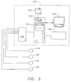
- a control interface section 120 samples analog data received from temperature sensor 110, economizer inlet valve 90, economizer bypass valve 92, and fuel heat exchanger bypass valve 94.
- Control interface section 120 converts the analog data to digital signals for subsequent processing.
- a computer 122 receives the sampled and digitized sensor data from control interface section 120 and performs high-speed data analysis.
- Computer 122 receives commands from an operator via a keyboard 124.
- An associated monitor 126 such as, but not limited to, a liquid crystal display (LCD) and/or a cathode ray tube, allows the operator to observe data received from computer 122.
- the operator supplied commands and parameters are used by computer 122 to provide control signals and information to control interface section 120.
- computer 122 includes a device 128, for example, a floppy disk drive, CD-ROM drive, DVD drive, magnetic optical disk (MOD) device, and/or any other digital device including a network connecting device such as an Ethernet device for reading instructions and/or data from a computer-readable medium 130, such as a floppy disk, a CD-ROM, a DVD or an other digital source such as a network or the Internet, as well as yet to be developed digital means.
- computer 122 executes instructions stored in firmware (not shown).
- Computer 122 is programmed to perform the functions described herein, and as used herein, the term computer is not limited to just those integrated circuits generally known as computers, but broadly refers to computers, processors, microcontrollers, microcomputers, programmable logic controllers, application specific integrated circuits, and other programmable circuits, and these terms are used interchangeably herein.
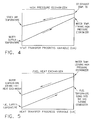
- FIGS 4 and 5 are graphical illustrations of fuel heating system 50 during normal operation.
- pump 72 is activated such that fuel 74, at a first temperature, is channeled through heat exchanger 70, and then into combustor 18.
- Control system 100 receives an input from temperature sensor 110 indicative of the temperature of fuel 74 entering combustor 18.
- An operator enters a preselected fuel temperature into control system 100 utilizing keyboard 124, for example. For example, the operator may enter a fuel temperature of 120 degrees.
- System 50 is then operated by control system 100 to facilitate either increasing or decreasing the temperature of fuel 74, such that fuel 74 has a temperature of approximately 120 degrees before being channeled into combustor 18.
- computer 122 operates economizer inlet valve 90, economizer bypass valve 92, and fuel heat exchanger bypass valve 94 to enable working fluid 86 to be channeled through heat exchanger 70 to facilitate either increasing or decreasing the operational temperature of fuel 74.
- computer 122 aligns secondary heating system 62 such that economizer inlet valve 90 is at least partially open, economizer bypass valve 92 is closed, and fuel heat exchanger bypass valve 94 is closed.
- pump 82 is operated such that working fluid 86, i.e. demineralized water, is channeled from storage tank 84 through economizer 80.
- economizer 80 is coupled within exhaust 46 such that the working fluid 86 within the secondary heating system 62 will extract the heat remaining in the exhaust gases discharged through exhaust duct 46 to facilitate increasing the operational temperature of working fluid 86 to a second temperature that is greater than the temperature of working fluid 86 prior to entering economizer 80.
- the heated working fluid 86 is then channeled through heat exchanger 70 wherein the heat rejected from working fluid 86 is utilized to increase an operating temperature of fuel 74 within heat exchanger 70.
- the heated fuel 74 is then channeled to combustor 18 and combusted within gas turbine engine 10.
- working fluid 86 is channeled through economizer 80 at a first temperature, the heat energy is then extracted from the exhaust gases discharged through exhaust duct 46 to facilitate increasing the operational temperature of working fluid 86 to a second temperature that is greater than the temperature of working fluid 86 prior to entering economizer 80. Additionally, the temperature of the operational temperature of the exhaust gases is decreased by transferring the heat energy from the exhaust gases to working fluid 86. Accordingly, channeling working fluid 86 through an economizer 80 that is located within exhaust stack 46 facilitates increasing an operational temperature of working fluid 86 and also facilitates reducing an operational temperature of the exhaust gases discharged through exhaust stack 46.
- economizer inlet valve 90 is in at least a partially open position, economizer bypass valve 92 is closed, and heat exchanger bypass valve 94 is in a closed position such that heated working fluid 86 discharged from economizer 80 is then channeled through heat exchanger 70 to facilitate increasing the operational temperature of fuel 74 and decreasing an operational temperature of working fluid 86. More specifically, to facilitate maintaining fuel 74 at the preselected temperature, control system 100 monitors the temperature of fuel 74 utilizing temperature sensor 110. As a result, economizer inlet valve 90 is repositioned to either increase or decrease the volume of working fluid 86 that is channeled through economizer 80 and heat exchanger 70 to facilitate maintaining the operational temperature of fuel 74 to the preselected temperature. The working fluid is then channeled from heat exchanger 70 through a check valve 146 and into combustor 18.
- channeling working fluid 86 through a heat exchanger 70 facilitates reducing the operational temperature of working fluid 86, prior to working fluid 86 being channeled into combustor 18, and also facilitates increasing an operational temperature of the fuel channeled into combustor 18.
- economizer inlet valve 90 is open, economizer bypass valve 92 is closed, and heat exchanger bypass valve 94 is at least partially open such that a first portion 150 heated working fluid 86 discharged from economizer 80 is channeled through heat exchanger 70 to facilitate increasing the operational temperature of fuel 74 and decreasing an operational temperature of working fluid 86 and a second portion 152 of heated working fluid is channeled through a check valve 154 wherein it is recombined with first portion 150 and channeled into combustor 18. More specifically, to facilitate maintaining fuel 74 at the preselected temperature, control system 100 monitors the temperature of fuel 74 utilizing temperature sensor 110.
- heat exchanger bypass valve 94 is repositioned to either increase or decrease the volume of working fluid 86 that is channeled through heat exchanger 70, i.e. by bypassing a portion 152 of the working fluid 86 around heat exchanger 70, to facilitate maintaining the operational temperature of fuel 74 at the preselected temperature.
- economizer inlet valve 90 is closed, economizer bypass valve 92 is at least partially opened, and heat exchanger bypass valve 94 is closed such that working fluid 86 is discharged from storage tank 84, through check valve 145 and into combustor 18.
- control system 100 based on temperature sensor 100, may configure system 62 to bypass heat exchanger 72 when fuel 74 is currently at the preselected temperature.
- heat exchanger bypass valve 94 is repositioned to either increase or decrease the volume of working fluid 86 that is channeled directly to combustor 18 to facilitate reducing nitrous oxide emissions from gas turbine engine 10.
- the above-described fuel heating system includes a fuel heating system that is configured to channel de-mineralized water from a storage tank through a pump wherein the demineralized water is split into two streams.
- One of the streams may be channeled through a high pressure economizer in the exhaust stack of the gas turbine engine, wherein the water is not allowed to boil by keeping the pressure of the water relative high.
- the water extracts the heat generated by the exhaust gases discharged from the gas turbine engine and channels the heated water to a fuel heat exchanger wherein a bypass valve is utilized to facilitate control the fuel temperature to a desired set point. Additionally, water from the second stream is added back to the stream flowing from the heat exchanger before it is injected into the combustor.
- Fuel heated in the fuel heat exchanger is also injected into the combustor to burn and provide heat to gases being expanded through the turbine. Accordingly, fuel may be heated in either simple and/or combined cycle gas turbine applications to temperatures as high as 400 degrees Fahrenheit using steam generated in the heat recovery boilers, thus increasing the efficiency of the power plant between 0.25% and approximately 0.5%. as shown in Table 1 below.
- heating the fuel and water results in substantial decrease in heat rate of the gas turbine engine.
- the heat rate of the gas turbine engine may be reduced by approximately 98 btu/KWH (British Thermal Unit/KiloWatt Hour) or approximately 1.26%, resulting in a savings of approximately $400,000 reduction in yearly fuel cost for a gas turbine operating approximately 8000 hours per year.
- the fuel heating system described herein also includes a control system that is utilized to sense the temperature of the heated fuel and provide control signals to various valves to facilitate controlling both the temperature of heated water and the fuel being injected into the combustor.
- Exemplary embodiments of a fuel heating system are described above in detail.
- the fuel heating system is not limited to the specific embodiments described herein, but rather, components of the system may be utilized independently and separately from other components described herein. Specifically, the fuel heating system described herein may be utilized on any known gas turbine engine.
- gas turbine engine assembly 10 gas turbine engine 14 low-pressure compressor 16 high-pressure compressor 18 combustor 20 high-pressure turbine 22 intermediate turbine 24 low-pressure turbine 26 inlet 28 outlet 30 inlet 32 outlet 34 inlet 36 outlet 40 first rotor shaft 42 second rotor shaft 43 longitudinal centerline axis 44 power turbine shaft 46 exhaust duct 50 fuel heating system 60 primary heating system 62 secondary heating system 70 heat exchanger 72 fuel pump 74 fuel 78 tank or reservoir 80 economizer 82 pump 84 tank or reservoir 86 working fluid 90 economizer inlet valve 92 economizer bypass valve 94 heat exchanger bypass valve 100 control system 110 temperature sensor 120 control interface section 122 computer 124 keyboard 126 monitor 128 device 130 computer-readable medium 145 check valve 146 check valve 150 first portion 152 second portion 154 check valve
Landscapes
- Engineering & Computer Science (AREA)
- Chemical & Material Sciences (AREA)
- Combustion & Propulsion (AREA)
- Mechanical Engineering (AREA)
- General Engineering & Computer Science (AREA)
- Engine Equipment That Uses Special Cycles (AREA)
Abstract
Description
- This invention relates generally to gas turbine engines, and more specifically to methods and apparatus for operating gas turbine engines.
- Gas turbine engines generally include, in serial flow arrangement, a high-pressure compressor for compressing air flowing through the engine, a combustor in which fuel is mixed with the compressed air and ignited to form a high temperature gas stream, and a high-pressure turbine. The high-pressure compressor, combustor and high-pressure turbine are sometimes collectively referred to as the core engine. Such gas turbine engines also may include a low-pressure compressor, or booster, for supplying compressed air to the high-pressure compressor.
- Air pollution concerns worldwide have led to stricter emissions standards both domestically and internationally. Pollutant emissions from at least some gas turbines are subject to Environmental Protection Agency (EPA) standards that regulate the emission of oxides of nitrogen (NOx), unburned hydrocarbons (HC), and carbon monoxide (CO). In general, engine emissions fall into two classes: those formed because of high flame temperatures (NOx), and those formed because of low flame temperatures that do not allow the fuel-air reaction to proceed to completion (HC & CO).
- Accordingly, at least one known gas turbine engine includes a water injection system that is configured to inject water into the combustor to facilitate reducing nitrous oxide emissions from the gas turbine engine by reducing the flame temperature in the combustor. However, injecting water into the combustor may also result in a significant decrease in the fuel efficiency of the gas turbine engine.
- In one aspect, a method for operating a gas turbine engine including a compressor, a combustor, and a turbine, coupled together in serial flow arrangement, and a fuel heating system including a heat exchanger and an economizer is provided. The method includes channeling fuel through the heat exchanger, channeling a working fluid through the heat exchanger to facilitate regulating the operating temperature of the fuel and the operating temperature of the working fluid, and channeling the fuel and the working fluid into the gas turbine engine combustor to facilitate increasing a fuel efficiency of the gas turbine engine.
- In another aspect, a fuel heating system for a gas turbine engine including at least a combustor and a turbine is provided. The fuel heating system includes a heat exchanger comprising a fuel circuit having fuel flowing therethrough and a working fluid circuit having a working fluid flowing therethrough to regulate the operating temperature of the fuel flowing through the fuel circuit, the heat exchanger configured to discharge fuel from the fuel circuit into the combustor, and to discharge the working fluid from the working fluid circuit to the combustor to facilitate increasing the fuel efficiency of the gas turbine engine.
- In a further aspect, a gas turbine engine assembly is provided. The gas turbine engine assembly includes a compressor, a combustor downstream from the compressor, a turbine coupled in flow communication with the combustor, and a fuel heating system. The fuel heating system includes a heat exchanger comprising a fuel circuit having fuel flowing therethrough and a working fluid circuit having a working fluid flowing therethrough to regulate the operating temperature of the fuel flowing through the fuel circuit, the heat exchanger configured to discharge fuel from the fuel circuit into the combustor, and to discharge the working fluid from the working fluid circuit to the combustor to facilitate increasing the fuel efficiency of the gas turbine engine.
- Embodiments of the present invention will now be described, by way of example only, with reference to the accompanying drawings, in which:
- Figure 1 is an exemplary gas turbine engine including a fuel heating system;
- Figure 2 is a block diagram of the exemplary fuel heating system in Figure 1;
- Figure 3 is a block diagram of a portion of the fuel heating system shown in Figures I and 2;
- Figure 4 is a graphical illustration of the high-pressure economizer shown in Figure 2 during normal operation; and
- Figure 5 is a graphical illustration of the heat exchanger shown in Figure 2 during normal operation
- Figure 1 is a block diagram of a gas
turbine engine assembly 8 including agas turbine engine 10 and afuel heating system 50.Gas turbine engine 10 includes, in serial flow relationship, a low-pressure compressor orbooster 14, a high-pressure compressor 16, acombustor 18, a high-pressure turbine 20, a low-pressure, orintermediate turbine 22, and a power turbine orfree turbine 24. Low-pressure compressor orbooster 14 has aninlet 26 and anoutlet 28, and high-pressure compressor 16 includes aninlet 30 and anoutlet 32. Combustor 18 has aninlet 34 that is substantially coincident with high-pressure compressor outlet 32, and anoutlet 36. - High-
pressure turbine 20 is coupled to high-pressure compressor 16 with afirst rotor shaft 40, and low-pressure turbine 22 is coupled to low-pressure compressor 14 with asecond rotor shaft 42.Rotor shafts longitudinal centerline axis 43 ofengine 10.Engine 10 may be used to drive a load, not shown, which may be coupled to apower turbine shaft 44. Optionally, the load may be coupled to a forward extension, not shown, ofrotor shaft 42. - In operation, ambient air, drawn into low-
pressure compressor inlet 26, is compressed and channeled downstream to high-pressure compressor 16. High-pressure compressor 16 further compresses the air and delivers high-pressure air tocombustor 18 where it is mixed with fuel, and the mixture is ignited to generate high temperature combustion gases. The combustion gases are channeled fromcombustor 18 to driveturbines exhaust duct 46 to ambient. - Figure 2 is a block diagram of the exemplary
fuel heating system 50 shown in Figure 1. The fuel efficiency ofengine 10 is at least partially related to the temperature of the fuel injected into gasturbine engine combustor 18. Accordingly, increasing a temperature of thefuel entering combustor 18 generally results in increasing the overall efficiency ofgas turbine engine 10. To facilitate increasing the operational temperature of thefuel entering combustor 18,fuel heating system 50 includes a first orprimary heating system 60 and a second or secondary heating system 62.Primary heating system 60 includes aheat exchanger 70 and apump 72.Primary heating system 60 is operated in a substantially open-loop configuration and includes afuel 74 flowing therethrough that is channeled tocombustor 18 and utilized in the combustion process. In the exemplary embodiment,primary heating system 60 also includes a tank orreservoir 78 to facilitate storingfuel 74. - Secondary heating system 62 includes a heat exchanger or
economizer 80, apump 82, and a tank orreservoir 84 to facilitate storing a workingfluid 86 and to facilitate adding additional workingfluid 86 to secondary heating system 62 as desired. In the exemplary embodiment, workingfluid 86 is demineralized water that is stored withintank 84 and channeled tocombustor 18 to facilitate reducing nitrous oxide emissions fromgas turbine engine 10. In the exemplary embodiment, secondary heating system 62 is operated in a substantially open-loop configuration and includes aneconomizer inlet valve 90, aneconomizer bypass valve 92, and a fuel heatexchanger bypass valve 94. -
Fuel heating system 50 also includes acontrol system 100 that is configured to control the operation offuel heating system 50. More specifically, and in the exemplary embodiment,control system 100 includes atemperature sensor 110 that is coupled toprimary heating system 60. More specifically,temperature sensor 110 is configured to sense the temperature offuel 74 that is discharged fromheat exchanger 70 and channeled tocombustor 18. In the exemplary embodiment,control system 100 is also electrically coupled toeconomizer inlet valve 90,economizer bypass valve 92, and fuel heatexchanger bypass valve 94, respectively. More specifically,control system 100 is configured to open/closeeconomizer inlet valve 90, aneconomizer bypass valve 92, and a fuel heatexchanger bypass valve 94 based on inputs received fromtemperature sensor 110, or optionally, inputs received from an operator. - As shown in Figure 3, a
control interface section 120 samples analog data received fromtemperature sensor 110,economizer inlet valve 90,economizer bypass valve 92, and fuel heatexchanger bypass valve 94.Control interface section 120 converts the analog data to digital signals for subsequent processing. Acomputer 122 receives the sampled and digitized sensor data fromcontrol interface section 120 and performs high-speed data analysis. -
Computer 122 receives commands from an operator via akeyboard 124. An associatedmonitor 126 such as, but not limited to, a liquid crystal display (LCD) and/or a cathode ray tube, allows the operator to observe data received fromcomputer 122. The operator supplied commands and parameters are used bycomputer 122 to provide control signals and information to controlinterface section 120. - In one embodiment,
computer 122 includes adevice 128, for example, a floppy disk drive, CD-ROM drive, DVD drive, magnetic optical disk (MOD) device, and/or any other digital device including a network connecting device such as an Ethernet device for reading instructions and/or data from a computer-readable medium 130, such as a floppy disk, a CD-ROM, a DVD or an other digital source such as a network or the Internet, as well as yet to be developed digital means. In another embodiment,computer 122 executes instructions stored in firmware (not shown).Computer 122 is programmed to perform the functions described herein, and as used herein, the term computer is not limited to just those integrated circuits generally known as computers, but broadly refers to computers, processors, microcontrollers, microcomputers, programmable logic controllers, application specific integrated circuits, and other programmable circuits, and these terms are used interchangeably herein. - Figures 4 and 5 are graphical illustrations of
fuel heating system 50 during normal operation. In the exemplary embodiment,pump 72 is activated such thatfuel 74, at a first temperature, is channeled throughheat exchanger 70, and then intocombustor 18.Control system 100 then receives an input fromtemperature sensor 110 indicative of the temperature offuel 74 enteringcombustor 18. An operator enters a preselected fuel temperature intocontrol system 100 utilizingkeyboard 124, for example. For example, the operator may enter a fuel temperature of 120 degrees.System 50 is then operated bycontrol system 100 to facilitate either increasing or decreasing the temperature offuel 74, such thatfuel 74 has a temperature of approximately 120 degrees before being channeled intocombustor 18. - More specifically, based on the input received from
temperature sensor 110,computer 122 operateseconomizer inlet valve 90,economizer bypass valve 92, and fuel heatexchanger bypass valve 94 to enable workingfluid 86 to be channeled throughheat exchanger 70 to facilitate either increasing or decreasing the operational temperature offuel 74. - For example, in one embodiment,
computer 122 aligns secondary heating system 62 such thateconomizer inlet valve 90 is at least partially open,economizer bypass valve 92 is closed, and fuel heatexchanger bypass valve 94 is closed. During operation, pump 82 is operated such that workingfluid 86, i.e. demineralized water, is channeled fromstorage tank 84 througheconomizer 80. - As shown in Figure 2, and in the exemplary embodiment,
economizer 80 is coupled withinexhaust 46 such that the workingfluid 86 within the secondary heating system 62 will extract the heat remaining in the exhaust gases discharged throughexhaust duct 46 to facilitate increasing the operational temperature of workingfluid 86 to a second temperature that is greater than the temperature of workingfluid 86 prior to enteringeconomizer 80. In one embodiment, the heated workingfluid 86 is then channeled throughheat exchanger 70 wherein the heat rejected from workingfluid 86 is utilized to increase an operating temperature offuel 74 withinheat exchanger 70. Theheated fuel 74 is then channeled tocombustor 18 and combusted withingas turbine engine 10. - More specifically, as shown in Figure 4, working
fluid 86 is channeled througheconomizer 80 at a first temperature, the heat energy is then extracted from the exhaust gases discharged throughexhaust duct 46 to facilitate increasing the operational temperature of workingfluid 86 to a second temperature that is greater than the temperature of workingfluid 86 prior to enteringeconomizer 80. Additionally, the temperature of the operational temperature of the exhaust gases is decreased by transferring the heat energy from the exhaust gases to workingfluid 86. Accordingly, channeling workingfluid 86 through aneconomizer 80 that is located withinexhaust stack 46 facilitates increasing an operational temperature of workingfluid 86 and also facilitates reducing an operational temperature of the exhaust gases discharged throughexhaust stack 46. - In one exemplary embodiment,
economizer inlet valve 90 is in at least a partially open position,economizer bypass valve 92 is closed, and heatexchanger bypass valve 94 is in a closed position such that heated workingfluid 86 discharged fromeconomizer 80 is then channeled throughheat exchanger 70 to facilitate increasing the operational temperature offuel 74 and decreasing an operational temperature of workingfluid 86. More specifically, to facilitate maintainingfuel 74 at the preselected temperature,control system 100 monitors the temperature offuel 74 utilizingtemperature sensor 110. As a result,economizer inlet valve 90 is repositioned to either increase or decrease the volume of workingfluid 86 that is channeled througheconomizer 80 andheat exchanger 70 to facilitate maintaining the operational temperature offuel 74 to the preselected temperature. The working fluid is then channeled fromheat exchanger 70 through a check valve 146 and intocombustor 18. - Accordingly, as shown in Figure 5, channeling working
fluid 86 through aheat exchanger 70 facilitates reducing the operational temperature of workingfluid 86, prior to workingfluid 86 being channeled intocombustor 18, and also facilitates increasing an operational temperature of the fuel channeled intocombustor 18. - In another exemplary embodiment,
economizer inlet valve 90 is open,economizer bypass valve 92 is closed, and heatexchanger bypass valve 94 is at least partially open such that afirst portion 150 heated workingfluid 86 discharged fromeconomizer 80 is channeled throughheat exchanger 70 to facilitate increasing the operational temperature offuel 74 and decreasing an operational temperature of workingfluid 86 and a second portion 152 of heated working fluid is channeled through acheck valve 154 wherein it is recombined withfirst portion 150 and channeled intocombustor 18. More specifically, to facilitate maintainingfuel 74 at the preselected temperature,control system 100 monitors the temperature offuel 74 utilizingtemperature sensor 110. As a result, heatexchanger bypass valve 94 is repositioned to either increase or decrease the volume of workingfluid 86 that is channeled throughheat exchanger 70, i.e. by bypassing a portion 152 of the workingfluid 86 aroundheat exchanger 70, to facilitate maintaining the operational temperature offuel 74 at the preselected temperature. - In another exemplary embodiment,
economizer inlet valve 90 is closed,economizer bypass valve 92 is at least partially opened, and heatexchanger bypass valve 94 is closed such that workingfluid 86 is discharged fromstorage tank 84, throughcheck valve 145 and intocombustor 18. More specifically,control system 100, based ontemperature sensor 100, may configure system 62 to bypassheat exchanger 72 whenfuel 74 is currently at the preselected temperature. As a result, heatexchanger bypass valve 94 is repositioned to either increase or decrease the volume of workingfluid 86 that is channeled directly tocombustor 18 to facilitate reducing nitrous oxide emissions fromgas turbine engine 10. - The above-described fuel heating system includes a fuel heating system that is configured to channel de-mineralized water from a storage tank through a pump wherein the demineralized water is split into two streams. One of the streams may be channeled through a high pressure economizer in the exhaust stack of the gas turbine engine, wherein the water is not allowed to boil by keeping the pressure of the water relative high. The water extracts the heat generated by the exhaust gases discharged from the gas turbine engine and channels the heated water to a fuel heat exchanger wherein a bypass valve is utilized to facilitate control the fuel temperature to a desired set point. Additionally, water from the second stream is added back to the stream flowing from the heat exchanger before it is injected into the combustor. Fuel heated in the fuel heat exchanger is also injected into the combustor to burn and provide heat to gases being expanded through the turbine. Accordingly, fuel may be heated in either simple and/or combined cycle gas turbine applications to temperatures as high as 400 degrees Fahrenheit using steam generated in the heat recovery boilers, thus increasing the efficiency of the power plant between 0.25% and approximately 0.5%. as shown in Table 1 below.
Table 1 ENGINE PERFORMANCE MODEL CASE Tfuel Power Heat rate water flow Twater Deg F MW BTU/KWH PPS Deg F 107 77 100.22 7732.8 10.26 77 207 180 100.17 7718.1 10.58 77 307 365 100.08 7687.5 11.1 77 407 77 100.18 7683.9 10.74 250 507 180 100.13 7667.8 11.08 250 607 365 100.04 7635.1 11.62 250 - As shown in Table 1, heating the fuel and water results in substantial decrease in heat rate of the gas turbine engine. For example, increasing the temperature of the fuel from 77° F to 250° F and increasing the temperature of the water from 77° F to 365° F , the heat rate of the gas turbine engine may be reduced by approximately 98 btu/KWH (British Thermal Unit/KiloWatt Hour) or approximately 1.26%, resulting in a savings of approximately $400,000 reduction in yearly fuel cost for a gas turbine operating approximately 8000 hours per year.
- The fuel heating system described herein also includes a control system that is utilized to sense the temperature of the heated fuel and provide control signals to various valves to facilitate controlling both the temperature of heated water and the fuel being injected into the combustor.
- Exemplary embodiments of a fuel heating system are described above in detail. The fuel heating system is not limited to the specific embodiments described herein, but rather, components of the system may be utilized independently and separately from other components described herein. Specifically, the fuel heating system described herein may be utilized on any known gas turbine engine.
- While the invention has been described in terms of various specific embodiments, those skilled in the art will recognize that the invention can be practiced with modification within the spirit and scope of the claims.
-
8 gas turbine engine assembly 10 gas turbine engine 14 low- pressure compressor 16 high- pressure compressor 18 combustor 20 high- pressure turbine 22 intermediate turbine 24 low- pressure turbine 26 inlet 28 outlet 30 inlet 32 outlet 34 inlet 36 outlet 40 first rotor shaft 42 second rotor shaft 43 longitudinal centerline axis 44 power turbine shaft 46 exhaust duct 50 fuel heating system 60 primary heating system 62 secondary heating system 70 heat exchanger 72 fuel pump 74 fuel 78 tank or reservoir 80 economizer 82 pump 84 tank or reservoir 86 working fluid 90 economizer inlet valve 92 economizer bypass valve 94 heat exchanger bypass valve 100 control system 110 temperature sensor 120 control interface section 122 computer 124 keyboard 126 monitor 128 device 130 computer- readable medium 145 check valve 146 check valve 150 first portion 152 second portion 154 check valve
Claims (10)
- A fuel heating system (50) for a gas turbine engine (10) including at least a combustor (18) and a turbine (20, 22, 24), said fuel heating system comprising:a heat exchanger (70) comprising a fuel circuit having fuel flowing therethrough and a working fluid circuit having a working fluid flowing therethrough to regulate the operating temperature of the fuel flowing through the fuel circuit, said heat exchanger configured to discharge fuel from said fuel circuit into the combustor, and to discharge the working fluid from said working fluid circuit to the combustor to facilitate increasing the fuel efficiency of the gas turbine engine.
- A fuel heating system (50) in accordance with Claim 1 further comprising an economizer (80) coupled in flow communication with said heat exchanger (70) working fluid circuit, said economizer configured to extract energy from gas turbine engine exhaust gases to facilitate increasing an operating temperature of the working fluid channeled therethrough.
- A fuel heating system (50) in accordance with Claim 1 wherein said working fluid comprises demineralized water, said working fluid circuit configured to channel demineralized water into the gas turbine engine combustor (18) to facilitate reducing nitrous oxide emissions generated by the gas turbine engine (10).
- A fuel heating system (50) in accordance with Claim 2 further comprising a first valve (92) to regulate the flow of working fluid channeled through said economizer (80) and said heat exchanger working fluid circuit.
- A fuel heating system (50) in accordance with Claim 4 further comprising a second valve (94) to regulate the flow of working fluid bypassed around said heat exchanger (70) working fluid circuit.
- A fuel heating circuit in accordance with Claim 5 further comprising:a fuel temperature sensor (110) configured to sense the temperature of the fuel channeled from said fuel circuit to the combustor (18); anda control system (100) coupled to said fuel temperature sensor, said control system configured to operate said second valve (94) to regulate the flow of working fluid channeled through said working fluid circuit based on an input received from said fuel temperature sensor.
- A fuel heating system (50) in accordance with Claim 6 wherein said control system (100) is configured to operate said first and second valves (92, 94) to regulate the flow of working fluid channeled through said working fluid circuit based on a preselected fuel temperature.
- A gas turbine engine assembly (8) comprising:a compressor (14, 16);a combustor (18) downstream from said compressor;a turbine (20, 22, 24) coupled in flow communication with said combustor; anda fuel heating system (50) comprising:a heat exchanger (70) comprising a fuel circuit having fuel flowing therethrough and a working fluid circuit having a working fluid flowing therethrough to regulate the operating temperature of the fuel flowing through the fuel circuit, said heat exchanger configured to discharge fuel from said fuel circuit into the combustor, and to discharge the working fluid from said working fluid circuit to the combustor to facilitate increasing the fuel efficiency of the gas turbine engine (10).
- A gas turbine engine assembly (8) in accordance with Claim 8 further comprising an economizer (80) coupled in flow communication with said heat exchanger working fluid circuit, said economizer configured to extract energy from gas turbine engine exhaust gases to facilitate increasing an operating temperature of the working fluid channeled therethrough.
- A gas turbine engine assembly (8) in accordance with Claim 8 wherein said working fluid comprises demineralized water, said working fluid circuit configured to channel demineralized water into the gas turbine engine combustor (18) to facilitate reducing nitrous oxide emissions generated by the gas turbine engine (10).
Applications Claiming Priority (1)
| Application Number | Priority Date | Filing Date | Title |
|---|---|---|---|
| US11/264,234 US7487642B2 (en) | 2005-11-01 | 2005-11-01 | Methods and apparatus for operating gas turbine engines |
Publications (3)
| Publication Number | Publication Date |
|---|---|
| EP1780389A2 true EP1780389A2 (en) | 2007-05-02 |
| EP1780389A3 EP1780389A3 (en) | 2014-04-09 |
| EP1780389B1 EP1780389B1 (en) | 2016-10-12 |
Family
ID=37575724
Family Applications (1)
| Application Number | Title | Priority Date | Filing Date |
|---|---|---|---|
| EP06255562.8A Not-in-force EP1780389B1 (en) | 2005-11-01 | 2006-10-30 | Fuel heating system for a gas turbine engine and gas turbine engine |
Country Status (4)
| Country | Link |
|---|---|
| US (1) | US7487642B2 (en) |
| EP (1) | EP1780389B1 (en) |
| JP (1) | JP4902313B2 (en) |
| CA (1) | CA2565743C (en) |
Cited By (1)
| Publication number | Priority date | Publication date | Assignee | Title |
|---|---|---|---|---|
| CN104100381A (en) * | 2013-04-09 | 2014-10-15 | 通用电气公司 | Simple cycle gas turbomachine system having a fuel conditioning system |
Families Citing this family (20)
| Publication number | Priority date | Publication date | Assignee | Title |
|---|---|---|---|---|
| US7874156B2 (en) * | 2007-03-29 | 2011-01-25 | General Electric Company | Methods and apparatus for heating a fluid |
| US7647777B2 (en) * | 2008-06-20 | 2010-01-19 | Gas Turbine Efficiency Sweden Ab | Skid architecture for a power augmentation system |
| US8205451B2 (en) * | 2008-08-05 | 2012-06-26 | General Electric Company | System and assemblies for pre-heating fuel in a combined cycle power plant |
| JP2012516984A (en) | 2009-02-04 | 2012-07-26 | パーデュ リサーチ ファンデーション | Bladed heat exchanger for metal hydride storage system |
| KR20120042713A (en) | 2009-02-04 | 2012-05-03 | 퍼듀 리서치 파운데이션 | Coiled and microchannel heat exchangers for metal hydride storage systems |
| US20100242489A1 (en) * | 2009-03-31 | 2010-09-30 | Rajarshi Saha | Systems, Methods, and Apparatus for Modifying Power Output and Efficiency of a Combined Cycle Power Plant |
| US9354618B2 (en) | 2009-05-08 | 2016-05-31 | Gas Turbine Efficiency Sweden Ab | Automated tuning of multiple fuel gas turbine combustion systems |
| US9671797B2 (en) | 2009-05-08 | 2017-06-06 | Gas Turbine Efficiency Sweden Ab | Optimization of gas turbine combustion systems low load performance on simple cycle and heat recovery steam generator applications |
| US9267443B2 (en) | 2009-05-08 | 2016-02-23 | Gas Turbine Efficiency Sweden Ab | Automated tuning of gas turbine combustion systems |
| US8437941B2 (en) * | 2009-05-08 | 2013-05-07 | Gas Turbine Efficiency Sweden Ab | Automated tuning of gas turbine combustion systems |
| WO2011068880A2 (en) * | 2009-12-01 | 2011-06-09 | Areva Solar, Inc. | Utilizing steam and/or hot water generated using solar energy |
| US20130205797A1 (en) * | 2012-02-14 | 2013-08-15 | General Electric Company | Fuel heating system for power plant |
| US9222415B2 (en) | 2012-03-06 | 2015-12-29 | Hamilton Sundstrand Corporation | Gas turbine engine fuel heating system |
| US9086019B2 (en) | 2012-07-02 | 2015-07-21 | United Technologies Corporation | Turbomachine thermal energy exchange |
| US9322295B2 (en) | 2012-10-17 | 2016-04-26 | General Electric Company | Thermal energy storage unit with steam and gas turbine system |
| US9376962B2 (en) | 2012-12-14 | 2016-06-28 | General Electric Company | Fuel gas heating with thermal energy storage |
| JP7619824B2 (en) * | 2021-02-15 | 2025-01-22 | 三菱重工業株式会社 | Gas turbine plant and fuel supply method therefor |
| US12173650B2 (en) | 2022-10-25 | 2024-12-24 | Ge Infrastructure Technology Llc | Combined cycle power plant having reduced parasitic pumping losses |
| US12031457B2 (en) | 2022-10-25 | 2024-07-09 | Ge Infrastructure Technology Llc | Combined cycle power plant having reduced parasitic pumping losses |
| EP4393825A1 (en) * | 2022-12-28 | 2024-07-03 | Airbus Operations, S.L.U. | Fuel conditioning system |
Family Cites Families (13)
| Publication number | Priority date | Publication date | Assignee | Title |
|---|---|---|---|---|
| US2602289A (en) * | 1945-05-25 | 1952-07-08 | Rateau Soc | Method and means for propelling a vehicle using normally gaseous fuel as a liquid |
| JPS5775132A (en) * | 1980-10-29 | 1982-05-11 | Shin Etsu Chem Co Ltd | Production of ball for polishing of grinding |
| US4932204A (en) * | 1989-04-03 | 1990-06-12 | Westinghouse Electric Corp. | Efficiency combined cycle power plant |
| GB2299377A (en) * | 1995-03-29 | 1996-10-02 | Cyril Timmins | Gas turbine powere generation system |
| JPH1193694A (en) * | 1997-09-18 | 1999-04-06 | Toshiba Corp | Gas turbine plant |
| US6050082A (en) | 1998-01-20 | 2000-04-18 | General Electric Company | Intercooled gas turbine engine with integral air bottoming cycle |
| JPH11303647A (en) * | 1998-04-23 | 1999-11-02 | Toshiba Plant Kensetsu Co Ltd | Combined power generation system |
| US6195607B1 (en) | 1999-07-06 | 2001-02-27 | General Electric Company | Method and apparatus for optimizing NOx emissions in a gas turbine |
| DE10041413B4 (en) * | 1999-08-25 | 2011-05-05 | Alstom (Switzerland) Ltd. | Method for operating a power plant |
| US6449953B1 (en) | 2000-04-28 | 2002-09-17 | General Electric Company | Methods for reducing gas turbine engine emissions |
| EP1199445A1 (en) * | 2000-10-17 | 2002-04-24 | Siemens Aktiengesellschaft | Apparatus and method of fuel preheating in combined gas and steam turbine plants |
| US6837056B2 (en) | 2002-12-19 | 2005-01-04 | General Electric Company | Turbine inlet air-cooling system and method |
| US7284377B2 (en) * | 2004-05-28 | 2007-10-23 | General Electric Company | Method and apparatus for operating an intercooler for a gas turbine engine |
-
2005
- 2005-11-01 US US11/264,234 patent/US7487642B2/en active Active
-
2006
- 2006-10-26 CA CA2565743A patent/CA2565743C/en not_active Expired - Fee Related
- 2006-10-26 JP JP2006290583A patent/JP4902313B2/en not_active Expired - Fee Related
- 2006-10-30 EP EP06255562.8A patent/EP1780389B1/en not_active Not-in-force
Cited By (2)
| Publication number | Priority date | Publication date | Assignee | Title |
|---|---|---|---|---|
| CN104100381A (en) * | 2013-04-09 | 2014-10-15 | 通用电气公司 | Simple cycle gas turbomachine system having a fuel conditioning system |
| CN104100381B (en) * | 2013-04-09 | 2018-01-16 | 通用电气公司 | Simple cycle gas turbine machinery system with fuel control system |
Also Published As
| Publication number | Publication date |
|---|---|
| US7487642B2 (en) | 2009-02-10 |
| EP1780389A3 (en) | 2014-04-09 |
| EP1780389B1 (en) | 2016-10-12 |
| JP4902313B2 (en) | 2012-03-21 |
| US20070095068A1 (en) | 2007-05-03 |
| CA2565743A1 (en) | 2007-05-01 |
| JP2007127125A (en) | 2007-05-24 |
| CA2565743C (en) | 2014-08-26 |
Similar Documents
| Publication | Publication Date | Title |
|---|---|---|
| EP1780389B1 (en) | Fuel heating system for a gas turbine engine and gas turbine engine | |
| US7284377B2 (en) | Method and apparatus for operating an intercooler for a gas turbine engine | |
| JP5184684B2 (en) | System and method for generating electricity | |
| JP3878684B2 (en) | Operation method of gas turbo equipment group | |
| CN101994580B (en) | Gas guide system for peripheral device of internal combustion engine, internal combustion engine and a method for operating the engine | |
| US10767855B2 (en) | Method and equipment for combustion of ammonia | |
| EP1917469B1 (en) | Method using a cogeneration system with oxygen-enriched air assisting system | |
| CN103375271A (en) | Apparatus relating to reheat combustion turbine engines with exhaust gas recirculation system | |
| US4907406A (en) | Combined gas turbine plant | |
| JP2013221500A (en) | Method and system for controlling extraction pressure and temperature of stoichiometric egr system | |
| CN103375254A (en) | Methods relating to reheat combustion turbine engines with exhaust gas recirculation | |
| JP2017503967A (en) | System and method for controlling a combustion process in a gas turbine operating with exhaust gas recirculation | |
| CN104769255A (en) | System and method for a stoichiometric exhaust gas recirculation gas turbine system | |
| EP1953352A2 (en) | Method and system for increasing modified Wobbe index control range of fuel gas | |
| CN107864660A (en) | Estimation with exhaust gas recirculatioon gas turbine combustion equivalent than system and method | |
| CN104411950A (en) | Methods and apparatus for co-firing fuel | |
| KR20220138407A (en) | Systems and methods for management of a plurality of exhaust gas recirculation coolers | |
| US7254950B2 (en) | Methods and apparatus for operating gas turbine engines | |
| US20130008172A1 (en) | Systems and Methods for Modified Wobbe Index Control With Constant Fuel Temperature | |
| CN111911248B (en) | Combustion stability adjustment system and method for gas turbine | |
| WO2006129150A2 (en) | Practical method for improving the efficiency of cogeneration system | |
| US20240369224A1 (en) | Systems and methods for reducing emissions in gas turbine engines | |
| CN105074168A (en) | Stoichiometric combustion control for gas turbine system with exhaust gas recirculation | |
| CN103032169A (en) | Power plant | |
| CN217156441U (en) | Dual-fuel combustion test system |
Legal Events
| Date | Code | Title | Description |
|---|---|---|---|
| PUAI | Public reference made under article 153(3) epc to a published international application that has entered the european phase |
Free format text: ORIGINAL CODE: 0009012 |
|
| AK | Designated contracting states |
Kind code of ref document: A2 Designated state(s): AT BE BG CH CY CZ DE DK EE ES FI FR GB GR HU IE IS IT LI LT LU LV MC NL PL PT RO SE SI SK TR |
|
| AX | Request for extension of the european patent |
Extension state: AL BA HR MK YU |
|
| PUAL | Search report despatched |
Free format text: ORIGINAL CODE: 0009013 |
|
| AK | Designated contracting states |
Kind code of ref document: A3 Designated state(s): AT BE BG CH CY CZ DE DK EE ES FI FR GB GR HU IE IS IT LI LT LU LV MC NL PL PT RO SE SI SK TR |
|
| AX | Request for extension of the european patent |
Extension state: AL BA HR MK RS |
|
| RIC1 | Information provided on ipc code assigned before grant |
Ipc: F02C 7/224 20060101AFI20140304BHEP Ipc: F02C 3/30 20060101ALI20140304BHEP |
|
| 17P | Request for examination filed |
Effective date: 20141009 |
|
| RBV | Designated contracting states (corrected) |
Designated state(s): AT BE BG CH CY CZ DE DK EE ES FI FR GB GR HU IE IS IT LI LT LU LV MC NL PL PT RO SE SI SK TR |
|
| AKX | Designation fees paid |
Designated state(s): DE FR GB |
|
| AXX | Extension fees paid |
Extension state: MK Extension state: BA Extension state: HR Extension state: AL Extension state: RS |
|
| GRAP | Despatch of communication of intention to grant a patent |
Free format text: ORIGINAL CODE: EPIDOSNIGR1 |
|
| INTG | Intention to grant announced |
Effective date: 20160621 |
|
| GRAS | Grant fee paid |
Free format text: ORIGINAL CODE: EPIDOSNIGR3 |
|
| GRAA | (expected) grant |
Free format text: ORIGINAL CODE: 0009210 |
|
| AK | Designated contracting states |
Kind code of ref document: B1 Designated state(s): DE FR GB |
|
| REG | Reference to a national code |
Ref country code: GB Ref legal event code: FG4D |
|
| REG | Reference to a national code |
Ref country code: FR Ref legal event code: PLFP Year of fee payment: 11 |
|
| REG | Reference to a national code |
Ref country code: DE Ref legal event code: R096 Ref document number: 602006050544 Country of ref document: DE |
|
| PGFP | Annual fee paid to national office [announced via postgrant information from national office to epo] |
Ref country code: FR Payment date: 20161123 Year of fee payment: 11 Ref country code: DE Payment date: 20161123 Year of fee payment: 11 Ref country code: GB Payment date: 20161027 Year of fee payment: 11 |
|
| REG | Reference to a national code |
Ref country code: DE Ref legal event code: R097 Ref document number: 602006050544 Country of ref document: DE |
|
| PLBE | No opposition filed within time limit |
Free format text: ORIGINAL CODE: 0009261 |
|
| STAA | Information on the status of an ep patent application or granted ep patent |
Free format text: STATUS: NO OPPOSITION FILED WITHIN TIME LIMIT |
|
| 26N | No opposition filed |
Effective date: 20170713 |
|
| REG | Reference to a national code |
Ref country code: DE Ref legal event code: R119 Ref document number: 602006050544 Country of ref document: DE |
|
| GBPC | Gb: european patent ceased through non-payment of renewal fee |
Effective date: 20171030 |
|
| REG | Reference to a national code |
Ref country code: FR Ref legal event code: ST Effective date: 20180629 |
|
| PG25 | Lapsed in a contracting state [announced via postgrant information from national office to epo] |
Ref country code: DE Free format text: LAPSE BECAUSE OF NON-PAYMENT OF DUE FEES Effective date: 20180501 Ref country code: GB Free format text: LAPSE BECAUSE OF NON-PAYMENT OF DUE FEES Effective date: 20171030 |
|
| PG25 | Lapsed in a contracting state [announced via postgrant information from national office to epo] |
Ref country code: FR Free format text: LAPSE BECAUSE OF NON-PAYMENT OF DUE FEES Effective date: 20171031 |