EP1780374A1 - Non frangible perforating gun system - Google Patents
Non frangible perforating gun system Download PDFInfo
- Publication number
- EP1780374A1 EP1780374A1 EP06022515A EP06022515A EP1780374A1 EP 1780374 A1 EP1780374 A1 EP 1780374A1 EP 06022515 A EP06022515 A EP 06022515A EP 06022515 A EP06022515 A EP 06022515A EP 1780374 A1 EP1780374 A1 EP 1780374A1
- Authority
- EP
- European Patent Office
- Prior art keywords
- charge
- shaped charge
- shaped
- gun housing
- assembly
- Prior art date
- Legal status (The legal status is an assumption and is not a legal conclusion. Google has not performed a legal analysis and makes no representation as to the accuracy of the status listed.)
- Withdrawn
Links
- 239000002800 charge carrier Substances 0.000 claims abstract description 83
- 238000005474 detonation Methods 0.000 claims abstract description 13
- 239000002360 explosive Substances 0.000 claims description 19
- 238000013467 fragmentation Methods 0.000 claims description 5
- 238000006062 fragmentation reaction Methods 0.000 claims description 5
- 239000000463 material Substances 0.000 description 22
- 230000015572 biosynthetic process Effects 0.000 description 5
- 238000005755 formation reaction Methods 0.000 description 5
- 239000007787 solid Substances 0.000 description 4
- 230000004888 barrier function Effects 0.000 description 3
- 239000012634 fragment Substances 0.000 description 3
- 239000007789 gas Substances 0.000 description 3
- 229910052751 metal Inorganic materials 0.000 description 3
- 239000002184 metal Substances 0.000 description 3
- 150000002739 metals Chemical class 0.000 description 3
- 235000020637 scallop Nutrition 0.000 description 3
- PXHVJJICTQNCMI-UHFFFAOYSA-N Nickel Chemical compound [Ni] PXHVJJICTQNCMI-UHFFFAOYSA-N 0.000 description 2
- 241000237509 Patinopecten sp. Species 0.000 description 2
- 239000003570 air Substances 0.000 description 2
- 239000004568 cement Substances 0.000 description 2
- 230000001419 dependent effect Effects 0.000 description 2
- 239000012530 fluid Substances 0.000 description 2
- 238000004519 manufacturing process Methods 0.000 description 2
- 238000000034 method Methods 0.000 description 2
- 239000004033 plastic Substances 0.000 description 2
- 229920003023 plastic Polymers 0.000 description 2
- 229910001369 Brass Inorganic materials 0.000 description 1
- RYGMFSIKBFXOCR-UHFFFAOYSA-N Copper Chemical compound [Cu] RYGMFSIKBFXOCR-UHFFFAOYSA-N 0.000 description 1
- 229920000742 Cotton Polymers 0.000 description 1
- 241000237503 Pectinidae Species 0.000 description 1
- 229910000831 Steel Inorganic materials 0.000 description 1
- 229910052782 aluminium Inorganic materials 0.000 description 1
- XAGFODPZIPBFFR-UHFFFAOYSA-N aluminium Chemical compound [Al] XAGFODPZIPBFFR-UHFFFAOYSA-N 0.000 description 1
- 239000012080 ambient air Substances 0.000 description 1
- 239000010951 brass Substances 0.000 description 1
- 238000004891 communication Methods 0.000 description 1
- 229910052802 copper Inorganic materials 0.000 description 1
- 239000010949 copper Substances 0.000 description 1
- 239000007799 cork Substances 0.000 description 1
- 230000002708 enhancing effect Effects 0.000 description 1
- 229930195733 hydrocarbon Natural products 0.000 description 1
- 150000002430 hydrocarbons Chemical class 0.000 description 1
- 230000000977 initiatory effect Effects 0.000 description 1
- 239000000203 mixture Substances 0.000 description 1
- 238000012986 modification Methods 0.000 description 1
- 230000004048 modification Effects 0.000 description 1
- 229910052759 nickel Inorganic materials 0.000 description 1
- 230000035515 penetration Effects 0.000 description 1
- 230000000704 physical effect Effects 0.000 description 1
- 238000005086 pumping Methods 0.000 description 1
- 230000000717 retained effect Effects 0.000 description 1
- 239000004576 sand Substances 0.000 description 1
- 230000035939 shock Effects 0.000 description 1
- 239000011359 shock absorbing material Substances 0.000 description 1
- 239000010959 steel Substances 0.000 description 1
- 238000005728 strengthening Methods 0.000 description 1
- 239000000126 substance Substances 0.000 description 1
- 239000000758 substrate Substances 0.000 description 1
- XLYOFNOQVPJJNP-UHFFFAOYSA-N water Substances O XLYOFNOQVPJJNP-UHFFFAOYSA-N 0.000 description 1
- 238000003466 welding Methods 0.000 description 1
- 239000002023 wood Substances 0.000 description 1
Images

Classifications
-
- E—FIXED CONSTRUCTIONS
- E21—EARTH OR ROCK DRILLING; MINING
- E21B—EARTH OR ROCK DRILLING; OBTAINING OIL, GAS, WATER, SOLUBLE OR MELTABLE MATERIALS OR A SLURRY OF MINERALS FROM WELLS
- E21B43/00—Methods or apparatus for obtaining oil, gas, water, soluble or meltable materials or a slurry of minerals from wells
- E21B43/11—Perforators; Permeators
- E21B43/116—Gun or shaped-charge perforators
- E21B43/117—Shaped-charge perforators
Definitions
- the invention relates generally to the field of oil and gas production. More specifically, the present invention relates to a non-frangible shaped charge system. Yet more specifically, the present invention relates to a perforating gun system that after detonation of its associated shaped charges minimizes wellbore gun fragments produced during well perforations.
- Perforating systems are used for the purpose, among others, of making hydraulic communication passages, called perforations, in wellbores drilled through earth formations so that predetermined zones of the earth formations can be hydraulically connected to the wellbore. Perforations are needed because wellbores are typically completed by coaxially inserting a pipe or casing into the wellbore, and the casing is retained in the wellbore by pumping cement into the annular space between the wellbore and the casing.
- the cemented casing is provided in the wellbore for the specific purpose of hydraulically isolating from each other the various earth formations penetrated by the wellbore.
- Perforating systems typically comprise one or more perforating guns strung together, these strings of guns can sometimes surpass a thousand feet of perforating length.
- shaped charges that typically include a housing, a liner, and a quantity of high explosive inserted between the liner and the housing.
- the high explosive When the high explosive is detonated, the force of the detonation collapses the liner and ejects it from one end of the charge at very high velocity in a pattern called a "jet".
- the jet penetrates the casing, the cement and a quantity of the formation.
- the present invention involves a shaped charge assembly comprising, a gun housing, a shaped charge housed within the gun housing, and a charge carrier disposed in the space between the gun housing and the shaped charge.
- the charge carrier fills at least a portion of the volume between the outer periphery of the shaped charge and the gun housing.
- the combined volume of the charge carrier and the shaped charge can range from about 20% to about 80% of the total empty volume of the gun housing inner space; the free volume within the gun housing can range from about 80% to about 20% of the total empty volume of the gun housing inner space.
- the combined volume of the charge carrier and the shaped charge can be about 65% of the total empty volume of the gun housing inner space.
- the free volume within the gun housing can be about 35% of the total empty volume of the gun housing inner space.
- the shaped charge has an open end, and the shaped charge assembly further comprise a gap in the region between the open end of the shaped charge and the gun housing.
- An explosive can be disposed within the shaped charge, wherein the charge carrier maintains the structural integrity of the shaped charge upon detonation of the explosive.
- the shaped charge assembly can further comprise a multiplicity of shaped charges.
- a multiplicity of bores may be disposed on the charge carrier formed to receive the multiplicity of shaped charges.
- the bores may be arranged perpendicular to the axis of the charge carrier and disposed at substantially the same radial location about the axis of the charge carrier.
- each bore may be arranged perpendicular to the axis of the charge carrier and spaced about the axis of the charge carrier at multiple radial locations.
- the bores may form a spiral pattern along the outer surface of the charge carrier.
- Each shaped charges may have an open end and wherein each shaped charge assembly may further comprise a gap in the region between each of the open ends and the gun housing.
- An explosive may be further included within each shaped charge, wherein the charge carrier maintains the structural integrity of each shaped charge upon detonation of the explosives.
- An orienting weight can optionally be included with the charge carrier.
- the charge carrier may comprise at least two modular segments. The modular segments may be configured in a phased arrangement.
- the charge carrier may be comprised of interconnected strands.
- a shaped charge assembly comprising, a gun housing, a shaped charge housed within the gun housing where the shaped charge includes a casing, a liner within the casing, and explosive between the casing and the liner.
- This embodiment of a shaped charge assembly includes a charge carrier disposed in the space between the gun housing and the shaped charge, wherein the charge carrier circumscribes the outer surface of the casing and minimizes fragmentation during detonation of the explosive.
- the combined volume of the charge carrier and the shaped charge can range from about 20% to about 80% of the total empty volume of the gun housing inner space and the free volume within the gun housing may range from about 80% to about 20% of the total empty volume of the gun housing inner space.
- the combined volume of the charge carrier and the shaped charge may be about 65% of the total empty volume of the gun housing inner space and the free volume within the gun housing can be about 35% of the total empty volume of the gun housing inner space.
- the shaped charges of this embodiment can be a phased arrangement, further the shaped charge assembly may additionally comprise an orienting weight.
- the charge carrier may optionally comprise at least two modular segments and can also be comprised of interconnected strands.
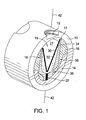
- Figure 1 depicts a cross sectional view of one embodiment of the present invention in a perspective aspect.
- this embodiment comprises a gun housing 10, a shaped charge 18, a charge carrier 16, and an optional orienting weight 14.
- strategic placement of the orienting weight 14 in combination with positioning the shaped charges 18 in a predetermined arrangement can orient the perforating system 6 within the wellbore thereby creating desired perforations within the wellbore.
- the gun housing 10 shown is an elongated member having a substantially cylindrical cross section.
- the gun housing 10 can include both a gun body or a gun tube, or any other structure capable of holding, housing, and/or positioning shaped charges 18 therein.
- the shape of the gun housing 10 is not limited to cylindrical cross sections, but can include other shapes, such as ones having multifaceted planar sides as hexagons, octagons, and the like.
- a gun tube (not shown) may be included with the shaped charge assembly and housed coaxially within the inner radius of the gun housing 10.
- the shaped charge 18 is housed within the inner radius of the gun housing 10 and oriented perpendicular to the length of the gun housing 10.
- the shaped charge 18 comprises a charge casing 34, explosive 32, and a liner 30.
- the device disclosed herein can be used with any type of shaped charge 18, either "off-the-shelf' or manufactured to specific size, shape, or performance specifications.
- the charge casing 34 is comprised of a base section 36 and walls 38.
- the walls 38 form a generally tube-like section extending up and away from the outer circumference of the base section 36.
- the space between the walls 38 and the base section 36 is formed to receive the explosive 32 and the liner 30.
- the base section 36 has a bowl-shaped inner periphery such that its inner and outer surfaces curve parallel to the axis 42 of the base section 36 as the surfaces travel away from the axis 42.
- the walls 38 and the base section 36 meet approximately at the point where the inner surface of the charge casing 34 is substantially parallel to the axis 42.
- the base section 36 further includes a booster charge 20 for initiation of the explosive 32 within the charge casing 34.
- the shaped charge 18 of Figure 1 is oriented within the gun housing 10 such that the open end 19 of the charge casing 34 points to the optional scallop 12 that is formed on the outer surface of the gun housing 10.
- the presence of the scallop 12 reduces the amount of gun housing material that the detonating charge must penetrate, thereby enhancing the performance of the shaped charge perforation penetration.
- the charge carrier 16 of the embodiment of Figure 1 occupies at least a portion of the space between the inner surface of the gun housing 10 and the charge casing 34. Also, the charge carrier 16 substantially circumscribes the outer surface of the charge casing 34 at its base and along its length, but the charge carrier does not extend into the region above the open end 19 of the shaped charge. A gap 21 exists between the open end 19 of the shaped charge 18 and the inner radius of the gun housing 10 to enable formation of the shaped charge jet as it exits the shaped charge 18. Additionally, in the embodiments that do not include an orienting weight 14, the charge carrier 16 could occupy the space where the orienting weight 14 resides.
- the free volume of the embodiment of Figure 1, i.e. the volume within the inner circumference of the gun housing 10 not occupied by the shaped charge 18, charge carrier 16, or orienting weight 14, can range from about 20% to about 80% of the total empty volume of the gun housing inner space.
- the free volume of the perforating system 6 can be occupied by ambient air, pressurized air, or some other gas at ambient or pressurized conditions.
- the substance that occupies the free space is not limited to gases, but can include other low-density matter.
- the solid volume, i.e. the total volume of the charge carrier 16 and shaped charge 18 (and optionally the orienting weight 14), can occupy the remaining space within the gun housing 10, and thus can range from about 80% to about 20% of the total empty volume of the gun housing inner space.
- the free space volume occupies around 35% of the total empty volume of the gun housing inner space.
- This embodiment thus provides for a volume of the charge carrier 16 and shaped charge 18 (and optionally the orienting weight 14) to be around 65% of the total empty volume of the gun housing inner space.
- These volume ratios of free space/solid volume are not dependent upon the number of shaped charges 18 within the charge carrier 16, but are applicable to charge carriers 16 having any number of associated shaped charges 18, even those having as little as one shaped charge 18.
- the charge carrier 16 should be capable of confining the shaped charge 18 during its detonation, thus the charge carrier material should have sufficient structural integrity to avoid being shattered or fragmented during operation.
- One criterion for choosing a proper material is to chose materials whose density exceeds 19 g/cc.
- suitable materials include metals such as steel, aluminum, nickel, brass, copper, and other ductile metals to name but a few.
- the material selection is not limited to metals, but can also include sand, cementitous materials, water, wood, plastics, and polymeric materials.
- the charge carrier 16 material need not be uniform, but can be comprised of a combination of two or more different types of materials.
- the charge carrier 16 can be comprised of different strata of materials where the materials differ along its height.
- high tensile bands (not shown) could be inserted within the bores 17 to provide a strengthening buffer around the shaped charges 18, while the remaining portion of the charge carrier 16 could be of a lower strength and subsequently lower density than the bands.
- the charge carrier 16 need not be solid but instead could have a design with multiple voids formed therein.
- An example might be a substrate comprised of multiple strands or weblike links structurally interconnected. More specific examples include a honeycomb structure 16a as shown in Figure 4a and an accordion structure 16b as shown in Figure 4b.
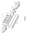
- FIG. 2 In the embodiment depicted in Figure 2 is shown in a perspective exploded view.
- the charge carrier 16 is shown having bores 17 formed therein perpendicular to the axis 28 of the charge carrier 16.
- the bores 17 extend through the charge carrier 16 and are profiled to match the profile of the walls 38 and base section 36 of the charge casing 34. Accordingly the bores 17 engagingly receive the shaped charges 18 within their inner periphery. While the bores 17 shown are aligned at roughly the same radial location on the charge carrier 16, the bores 17 can be formed at any radial location on the carrier 16.
- the shaped charges 18 can be "phased” such that they are positioned within the perforating system 6 to detonate at multiple radial locations around the charge carrier 16.
- the specific shaped charge phasing is dependent on the particular application of the perforating system 6 and thus many phasing scenarios are available.
- connectors 22 for connecting the adjacent segments of the perforating system 6.
- stop ring 24 that is used in securing the charge carrier 16 into a proper orientation so that the shaped charges 18 are aligned with their respective scallops 12.
- Adjacent bores 17 must have a sufficient amount of charge carrier material between them for withstanding the detonation force of the explosive to thereby prevent fragmentation of the charge carrier 16.
- the distance between adjacent bores 17 depends on the type of material used in forming the charge carrier 16.
- a charge carrier 16 formed from materials having low yield strength will require more material between adjacent bores 17 than a carrier 16 made from a material having high yield strength.
- Those skilled in the art can determine the required distance with regard to each specific material used in manufacturing the charge carrier 16 without undue experimentation.
- a certain amount of charge carrier 16 material must be present between the end of the charge carrier 16 and the outermost shaped charge 18 for bolstering the resiliency of the charge carrier end to prevent fragmentation during detonation of the shaped charge 18. How much material is required depends on the physical properties of the material - this also can be determined by those skilled in the art.
- Impedance barriers 26 can be formed on the charge carrier 16 between each bore 17.
- the impedance barriers 26 are troughs cut or formed perpendicular to the axis 28 of the charge carrier 26. These troughs can simply be air filled voids existing between the bores 17, or can be filled with shock absorbing material such as cotton, rubber, polymeric compositions, plastics, cork, felt, or like materials.
- shock absorbing material such as cotton, rubber, polymeric compositions, plastics, cork, felt, or like materials.
- the existence of the impedance barriers 26 serves to eliminate shock wave interference that can be transmitted from one shaped charge 18 to an adjacent shaped charge 18.
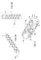
- the charge carrier 16a has a hexagonal cross section where the outer periphery is comprised of planar sides 15 connected at their respective ends. Bores 17 are formed within the sides 15, and can be placed in any pattern depending on the design requirements of the particular perforating system 6. Also, the embodiment of Figure 3a is not limited to six sided members, but can include any number of planar sides 15. With regard now to the embodiment of Figure 3b, here a charge carrier 16b is illustrated with associated bores 17 arranged in a spiral pattern along its length. Other slot patterns include a helical arrangement, multiple spirals, staggered, high density, or any other know known or later developed slot arrangement.
- FIG. 5 illustrates one embodiment of a charge carrier 16a comprised of modular segments (42a, 42b, 42c).
- the segments (42a, 42b, 42c) each have a bore 17a (shown in a dashed outline) formed through its upper face 44.
- each bore 17a has a shaped charge 18 disposed within.
- the lateral sides 46 of each segment (42a, 42b, 42c) is curved and formed to fit inside of a gun tube or gun body.
- the distal sides 48 of the segments (42a, 42b, 42c) are generally planar.
- Each segment is preferably affixed to each adjacent segment either by pins (not shown), welding, or any other type of fastening means suitable for securing the segments.
- the segments (42a, 42b, 42c) of Figure 5 are shown in a phased configuration, the segments (42a, 42b, 42c) can be aligned such that their respective shaped charges 34 could be fired in a straight line. It should be pointed out that the volume values discussed above are applicable to each individual segment, or the segments as a whole. For example, the combined volume of the segment 42a and its corresponding shaped charge 34a can range from about 80% to about 20% of the total empty volume of the inner space of the portion of the gun housing occupied by the segment 42a.
- the free volume that occupies the space between the segment 42a and its corresponding shaped charge 34 thus ranges from about 20% to about 80% of the total empty volume of the inner space of the portion of the gun housing occupied by the segment 42a.
- the combined volume of all segments (42a, 42b, 42c) and their respective shaped charges 34 can occupy from about 80% to about 20% of the total empty volume of the inner space of the portion of the gun housing occupied by these segments (42a, 42b, 42c).
- a free volume between the segments (42a, 42b, 42c) and their corresponding shaped charges 34 to range from about 20% to about 80% of the total empty volume of the inner space of the portion of the gun housing occupied by the segment 42a.
- the embodiment of Figure 5 includes a solid volume to free volume ratio of 65% to 35%, for individual segments and when combined as a whole.
Landscapes
- Geology (AREA)
- Life Sciences & Earth Sciences (AREA)
- Engineering & Computer Science (AREA)
- Mining & Mineral Resources (AREA)
- Environmental & Geological Engineering (AREA)
- Fluid Mechanics (AREA)
- Physics & Mathematics (AREA)
- General Life Sciences & Earth Sciences (AREA)
- Geochemistry & Mineralogy (AREA)
- Drilling And Exploitation, And Mining Machines And Methods (AREA)
- Solid Thermionic Cathode (AREA)
- Portable Nailing Machines And Staplers (AREA)
- Apparatus Associated With Microorganisms And Enzymes (AREA)
- Perforating, Stamping-Out Or Severing By Means Other Than Cutting (AREA)
- Preliminary Treatment Of Fibers (AREA)
Abstract
Description
- The invention relates generally to the field of oil and gas production. More specifically, the present invention relates to a non-frangible shaped charge system. Yet more specifically, the present invention relates to a perforating gun system that after detonation of its associated shaped charges minimizes wellbore gun fragments produced during well perforations.
- Perforating systems are used for the purpose, among others, of making hydraulic communication passages, called perforations, in wellbores drilled through earth formations so that predetermined zones of the earth formations can be hydraulically connected to the wellbore. Perforations are needed because wellbores are typically completed by coaxially inserting a pipe or casing into the wellbore, and the casing is retained in the wellbore by pumping cement into the annular space between the wellbore and the casing. The cemented casing is provided in the wellbore for the specific purpose of hydraulically isolating from each other the various earth formations penetrated by the wellbore.
- Perforating systems typically comprise one or more perforating guns strung together, these strings of guns can sometimes surpass a thousand feet of perforating length. Included with the perforating guns are shaped charges that typically include a housing, a liner, and a quantity of high explosive inserted between the liner and the housing. When the high explosive is detonated, the force of the detonation collapses the liner and ejects it from one end of the charge at very high velocity in a pattern called a "jet". The jet penetrates the casing, the cement and a quantity of the formation.
- Due to the high force caused by the explosive, the shaped charge and its associated components often shatter into many fragments that exit the perforating gun into the fluids within the wellbore. These fragments can clog as well as damage devices such as chokes and manifolds thereby restricting the flow of fluids through these devices and possibly hampering the amount of hydrocarbons produced from the particular wellbore. Therefore, there exists a need for an apparatus and a method for conducting perforating operations that can significantly reduce fragmentation of shaped charges.
- The present invention involves a shaped charge assembly comprising, a gun housing, a shaped charge housed within the gun housing, and a charge carrier disposed in the space between the gun housing and the shaped charge. The charge carrier fills at least a portion of the volume between the outer periphery of the shaped charge and the gun housing. The combined volume of the charge carrier and the shaped charge can range from about 20% to about 80% of the total empty volume of the gun housing inner space; the free volume within the gun housing can range from about 80% to about 20% of the total empty volume of the gun housing inner space. Optionally, the combined volume of the charge carrier and the shaped charge can be about 65% of the total empty volume of the gun housing inner space. In the optional embodiment, the free volume within the gun housing can be about 35% of the total empty volume of the gun housing inner space.
- In one embodiment of the present device, the shaped charge has an open end, and the shaped charge assembly further comprise a gap in the region between the open end of the shaped charge and the gun housing. An explosive can be disposed within the shaped charge, wherein the charge carrier maintains the structural integrity of the shaped charge upon detonation of the explosive. Moreover, the shaped charge assembly can further comprise a multiplicity of shaped charges. A multiplicity of bores may be disposed on the charge carrier formed to receive the multiplicity of shaped charges. The bores may be arranged perpendicular to the axis of the charge carrier and disposed at substantially the same radial location about the axis of the charge carrier. In another embodiment, each bore may be arranged perpendicular to the axis of the charge carrier and spaced about the axis of the charge carrier at multiple radial locations. Also, the bores may form a spiral pattern along the outer surface of the charge carrier.
- Each shaped charges may have an open end and wherein each shaped charge assembly may further comprise a gap in the region between each of the open ends and the gun housing. An explosive may be further included within each shaped charge, wherein the charge carrier maintains the structural integrity of each shaped charge upon detonation of the explosives.
- An orienting weight can optionally be included with the charge carrier. Also, the charge carrier may comprise at least two modular segments. The modular segments may be configured in a phased arrangement. In one alternative embodiment of the shaped charge assembly, the charge carrier may be comprised of interconnected strands.
- Also included with the present disclosure is a shaped charge assembly comprising, a gun housing, a shaped charge housed within the gun housing where the shaped charge includes a casing, a liner within the casing, and explosive between the casing and the liner. This embodiment of a shaped charge assembly includes a charge carrier disposed in the space between the gun housing and the shaped charge, wherein the charge carrier circumscribes the outer surface of the casing and minimizes fragmentation during detonation of the explosive. Here the combined volume of the charge carrier and the shaped charge can range from about 20% to about 80% of the total empty volume of the gun housing inner space and the free volume within the gun housing may range from about 80% to about 20% of the total empty volume of the gun housing inner space. Optionally in this embodiment, the combined volume of the charge carrier and the shaped charge may be about 65% of the total empty volume of the gun housing inner space and the free volume within the gun housing can be about 35% of the total empty volume of the gun housing inner space. The shaped charges of this embodiment can be a phased arrangement, further the shaped charge assembly may additionally comprise an orienting weight. The charge carrier may optionally comprise at least two modular segments and can also be comprised of interconnected strands.
-
- Figure 1 depicts a perspective cross sectional view of one embodiment of a charge carrier.
- Figure 2 illustrates a perspective view of one embodiment of the present invention.
- Figures 3a and 3b portray perspective views of embodiments of a charge carrier.
- Figures 4a and 4b depict alternative embodiments of the structure of a charge carrier.
- Figure 5 illustrates a segmented embodiment of a charge carrier.
- With reference to the drawings herein, Figure 1 depicts a cross sectional view of one embodiment of the present invention in a perspective aspect. As shown, this embodiment comprises a
gun housing 10, ashaped charge 18, acharge carrier 16, and anoptional orienting weight 14. As is known, strategic placement of theorienting weight 14 in combination with positioning theshaped charges 18 in a predetermined arrangement, can orient the perforatingsystem 6 within the wellbore thereby creating desired perforations within the wellbore. In the embodiment of Figure 1, thegun housing 10 shown is an elongated member having a substantially cylindrical cross section. For the purposes of the disclosure herein, thegun housing 10 can include both a gun body or a gun tube, or any other structure capable of holding, housing, and/or positioning shapedcharges 18 therein. However the shape of thegun housing 10 is not limited to cylindrical cross sections, but can include other shapes, such as ones having multifaceted planar sides as hexagons, octagons, and the like. Alternatively, a gun tube (not shown) may be included with the shaped charge assembly and housed coaxially within the inner radius of thegun housing 10. - As shown, the
shaped charge 18 is housed within the inner radius of the gun housing 10 and oriented perpendicular to the length of thegun housing 10. Theshaped charge 18 comprises acharge casing 34, explosive 32, and aliner 30. The device disclosed herein can be used with any type ofshaped charge 18, either "off-the-shelf' or manufactured to specific size, shape, or performance specifications. Thecharge casing 34 is comprised of abase section 36 andwalls 38. Thewalls 38 form a generally tube-like section extending up and away from the outer circumference of thebase section 36. The space between thewalls 38 and thebase section 36 is formed to receive the explosive 32 and theliner 30. Preferably thebase section 36 has a bowl-shaped inner periphery such that its inner and outer surfaces curve parallel to theaxis 42 of thebase section 36 as the surfaces travel away from theaxis 42. Thewalls 38 and thebase section 36 meet approximately at the point where the inner surface of thecharge casing 34 is substantially parallel to theaxis 42. Thebase section 36 further includes abooster charge 20 for initiation of the explosive 32 within thecharge casing 34. - The shaped
charge 18 of Figure 1 is oriented within thegun housing 10 such that theopen end 19 of thecharge casing 34 points to theoptional scallop 12 that is formed on the outer surface of thegun housing 10. As is known, the presence of thescallop 12 reduces the amount of gun housing material that the detonating charge must penetrate, thereby enhancing the performance of the shaped charge perforation penetration. - The
charge carrier 16 of the embodiment of Figure 1 occupies at least a portion of the space between the inner surface of thegun housing 10 and thecharge casing 34. Also, thecharge carrier 16 substantially circumscribes the outer surface of thecharge casing 34 at its base and along its length, but the charge carrier does not extend into the region above theopen end 19 of the shaped charge. Agap 21 exists between theopen end 19 of the shapedcharge 18 and the inner radius of thegun housing 10 to enable formation of the shaped charge jet as it exits the shapedcharge 18. Additionally, in the embodiments that do not include an orientingweight 14, thecharge carrier 16 could occupy the space where the orientingweight 14 resides. - The free volume of the embodiment of Figure 1, i.e. the volume within the inner circumference of the
gun housing 10 not occupied by the shapedcharge 18,charge carrier 16, or orientingweight 14, can range from about 20% to about 80% of the total empty volume of the gun housing inner space. The free volume of the perforatingsystem 6 can be occupied by ambient air, pressurized air, or some other gas at ambient or pressurized conditions. The substance that occupies the free space is not limited to gases, but can include other low-density matter. The solid volume, i.e. the total volume of thecharge carrier 16 and shaped charge 18 (and optionally the orienting weight 14), can occupy the remaining space within thegun housing 10, and thus can range from about 80% to about 20% of the total empty volume of the gun housing inner space. - In one embodiment of the present device, the free space volume occupies around 35% of the total empty volume of the gun housing inner space. This embodiment thus provides for a volume of the
charge carrier 16 and shaped charge 18 (and optionally the orienting weight 14) to be around 65% of the total empty volume of the gun housing inner space. These volume ratios of free space/solid volume are not dependent upon the number of shapedcharges 18 within thecharge carrier 16, but are applicable tocharge carriers 16 having any number of associated shapedcharges 18, even those having as little as one shapedcharge 18. - The
charge carrier 16 should be capable of confining the shapedcharge 18 during its detonation, thus the charge carrier material should have sufficient structural integrity to avoid being shattered or fragmented during operation. One criterion for choosing a proper material is to chose materials whose density exceeds 19 g/cc. Thus suitable materials include metals such as steel, aluminum, nickel, brass, copper, and other ductile metals to name but a few. The material selection is not limited to metals, but can also include sand, cementitous materials, water, wood, plastics, and polymeric materials. Moreover, thecharge carrier 16 material need not be uniform, but can be comprised of a combination of two or more different types of materials. For example, thecharge carrier 16 can be comprised of different strata of materials where the materials differ along its height. Also, high tensile bands (not shown) could be inserted within thebores 17 to provide a strengthening buffer around the shapedcharges 18, while the remaining portion of thecharge carrier 16 could be of a lower strength and subsequently lower density than the bands. It should be pointed out that thecharge carrier 16 need not be solid but instead could have a design with multiple voids formed therein. An example might be a substrate comprised of multiple strands or weblike links structurally interconnected. More specific examples include ahoneycomb structure 16a as shown in Figure 4a and anaccordion structure 16b as shown in Figure 4b. - In the embodiment depicted in Figure 2 is shown in a perspective exploded view. In Figure 2 the
charge carrier 16 is shown havingbores 17 formed therein perpendicular to theaxis 28 of thecharge carrier 16. Thebores 17 extend through thecharge carrier 16 and are profiled to match the profile of thewalls 38 andbase section 36 of thecharge casing 34. Accordingly thebores 17 engagingly receive the shapedcharges 18 within their inner periphery. While thebores 17 shown are aligned at roughly the same radial location on thecharge carrier 16, thebores 17 can be formed at any radial location on thecarrier 16. As with many perforating systems, the shapedcharges 18 can be "phased" such that they are positioned within the perforatingsystem 6 to detonate at multiple radial locations around thecharge carrier 16. The specific shaped charge phasing is dependent on the particular application of the perforatingsystem 6 and thus many phasing scenarios are available. Also shown in Figure 2 included with the perforatingsystem 6 areconnectors 22 for connecting the adjacent segments of the perforatingsystem 6. Also shown is astop ring 24 that is used in securing thecharge carrier 16 into a proper orientation so that the shapedcharges 18 are aligned with theirrespective scallops 12. -
Adjacent bores 17 must have a sufficient amount of charge carrier material between them for withstanding the detonation force of the explosive to thereby prevent fragmentation of thecharge carrier 16. The distance betweenadjacent bores 17 depends on the type of material used in forming thecharge carrier 16. Acharge carrier 16 formed from materials having low yield strength will require more material betweenadjacent bores 17 than acarrier 16 made from a material having high yield strength. Those skilled in the art can determine the required distance with regard to each specific material used in manufacturing thecharge carrier 16 without undue experimentation. Likewise, a certain amount ofcharge carrier 16 material must be present between the end of thecharge carrier 16 and the outermost shapedcharge 18 for bolstering the resiliency of the charge carrier end to prevent fragmentation during detonation of the shapedcharge 18. How much material is required depends on the physical properties of the material - this also can be determined by those skilled in the art. -
Impedance barriers 26 can be formed on thecharge carrier 16 between each bore 17. Theimpedance barriers 26 are troughs cut or formed perpendicular to theaxis 28 of thecharge carrier 26. These troughs can simply be air filled voids existing between thebores 17, or can be filled with shock absorbing material such as cotton, rubber, polymeric compositions, plastics, cork, felt, or like materials. The existence of theimpedance barriers 26 serves to eliminate shock wave interference that can be transmitted from one shapedcharge 18 to an adjacent shapedcharge 18. - Additional embodiments of the charge carrier (16a, 16b) are illustrated in Figures 3a and 3b. With respect to Figure 3a, the
charge carrier 16a has a hexagonal cross section where the outer periphery is comprised ofplanar sides 15 connected at their respective ends.Bores 17 are formed within thesides 15, and can be placed in any pattern depending on the design requirements of theparticular perforating system 6. Also, the embodiment of Figure 3a is not limited to six sided members, but can include any number ofplanar sides 15. With regard now to the embodiment of Figure 3b, here acharge carrier 16b is illustrated with associatedbores 17 arranged in a spiral pattern along its length. Other slot patterns include a helical arrangement, multiple spirals, staggered, high density, or any other know known or later developed slot arrangement. - Figure 5 illustrates one embodiment of a
charge carrier 16a comprised of modular segments (42a, 42b, 42c). Here the segments (42a, 42b, 42c) each have abore 17a (shown in a dashed outline) formed through itsupper face 44. As shown, eachbore 17a has a shapedcharge 18 disposed within. The lateral sides 46 of each segment (42a, 42b, 42c) is curved and formed to fit inside of a gun tube or gun body. Thedistal sides 48 of the segments (42a, 42b, 42c) are generally planar. Each segment is preferably affixed to each adjacent segment either by pins (not shown), welding, or any other type of fastening means suitable for securing the segments. - Although the segments (42a, 42b, 42c) of Figure 5 are shown in a phased configuration, the segments (42a, 42b, 42c) can be aligned such that their respective shaped
charges 34 could be fired in a straight line. It should be pointed out that the volume values discussed above are applicable to each individual segment, or the segments as a whole. For example, the combined volume of thesegment 42a and its corresponding shaped charge 34a can range from about 80% to about 20% of the total empty volume of the inner space of the portion of the gun housing occupied by thesegment 42a. Accordingly the free volume that occupies the space between thesegment 42a and its corresponding shapedcharge 34 thus ranges from about 20% to about 80% of the total empty volume of the inner space of the portion of the gun housing occupied by thesegment 42a. Similarly, the combined volume of all segments (42a, 42b, 42c) and their respective shapedcharges 34 can occupy from about 80% to about 20% of the total empty volume of the inner space of the portion of the gun housing occupied by these segments (42a, 42b, 42c). Thus resulting in a free volume between the segments (42a, 42b, 42c) and their corresponding shapedcharges 34 to range from about 20% to about 80% of the total empty volume of the inner space of the portion of the gun housing occupied by thesegment 42a. Moreover, the embodiment of Figure 5 includes a solid volume to free volume ratio of 65% to 35%, for individual segments and when combined as a whole. - While detonation of the shaped
charges 18 of the perforatingsystem 6 disclosed herein results in some damage to the component parts, the fragmented parts are contained within thegun housing 10. Accordingly when the perforatingsystem 6 is retrieved from the wellbore after use, either no debris, or a negligible amount of debris, remains within the borehole. Thus use of the present device substantially reduces the threat of clogging due to fractured component parts. - The present invention described herein, therefore, is well adapted to carry out the objects and attain the ends and advantages mentioned, as well as others inherent therein. While a presently preferred embodiment of the invention has been given for purposes of disclosure, numerous changes exist in the details of procedures for accomplishing the desired results. For example, the invention described herein is applicable to any shaped charge phasing as well as any density of shaped charge. Moreover, the invention can be utilized with any size of perforating gun. These and other similar modifications will readily suggest themselves to those skilled in the art, and are intended to be encompassed within the spirit of the present invention disclosed herein and the scope of the appended claims.
Claims (23)
- A shaped charge assembly comprising:a gun housing;a shaped charge housed within the gun housing; anda charge carrier disposed in the space between the gun housing and the shaped charge, wherein said charge carrier fills at least a portion of the volume between theouter periphery of the shaped charge and the gun housing.
- The shaped charge assembly of claim 1, wherein the combined volume of the charge carrier and the shaped charge ranges from about 20% to about 80% of the total empty volume of the gun housing inner space and wherein the free volume within the gun housing ranges from about 80% to about 20% of the total empty volume of the gun housing inner space.
- The shaped charge assembly of claim 1, wherein the combined volume of the charge carrier and the shaped charge is about 65% of the total empty volume of the gun housing inner space and wherein the free volume within the gun housing is about 35% of the total empty volume of the gun housing inner space.
- The shaped charge assembly of claim 1, wherein the shaped charge has an open end, said shaped charge assembly further comprising a gap in the region between the open end of the shaped charge and the gun housing.
- The shaped charge assembly of claim 1, further comprising an explosive within the shaped charge, wherein said charge carrier maintains the structural integrity of the shaped charge upon detonation of the explosive.
- The shaped charge assembly of claim 1 further comprising a multiplicity of shaped charges.
- The shaped charge assembly of claim 6 further comprising a multiplicity of bores disposed on said charge carrier, said bores formed to receive said multiplicity of shaped charges.
- The shaped charge assembly of claim 7, wherein each of said bores are arranged perpendicular to the axis of the charge carrier, and each of said bores are disposed at substantially the same radial location about the axis of the charge carrier.
- The shaped charge assembly of claim 7, wherein each of said bores are arranged perpendicular to the axis of the charge carrier, and each of said bores are spaced about the axis of the charge carrier at multiple radial locations.
- The shaped charge assembly of claim 7, wherein said bores form a spiral pattern along the outer surface of said charge carrier.
- The shaped charge assembly of claim 6, wherein each of said multiplicity of shaped charges has an open end and wherein said shaped charge assembly further comprises a gap in the region between each of said open ends and the gun housing.
- The shaped charge assembly of claim 11, further comprising explosive within each shaped charge, wherein said charge carrier maintains the structural integrity of each shaped charge upon detonation of the explosives.
- The shaped charge assembly of claim 1, further comprising an orienting weight.
- The shaped charge assembly of claim 1, wherein said charge carrier comprises at least two modular segments.
- The shaped charge assembly of claim 14, wherein said modular segments are configured in a phased arrangement.
- The shaped charge assembly of claim 1, wherein said charge carrier is comprised of interconnected strands.
- A shaped charge assembly comprising:a gun housing;a shaped charge housed within the gun housing, said shaped charge comprising a casing, a liner within the casing, and explosive between the casing and the liner; anda charge carrier disposed in the space between the gun housing and the shaped charge, wherein said charge carrier circumscribes the outer surface of said casing andminimizes fragmentation during detonation of the explosive.
- The shaped charge assembly of claim 17, wherein the combined volume of the charge carrier and the shaped charge ranges from about 20% to about 80% of the total empty volume of the gun housing inner space and wherein the free volume within the gun housing ranges from about 80% to about 20% of the total empty volume of the gun housing inner space.
- The shaped charge assembly of claim 17, wherein the combined volume of the charge carrier and the shaped charge is about 65% of the total empty volume of the gun housing inner space and wherein the free volume within the gun housing is about 35% of the total empty volume of the gun housing inner space.
- The shaped charge assembly of claim 17, wherein said shaped charges are in a phased arrangement.
- The shaped charge assembly of claim 17, further comprising an orienting weight.
- The shaped charge assembly of claim 17, wherein said charge carrier comprises at least two modular segments.
- The shaped charge assembly of claim 17, wherein said charge carrier is comprised of interconnected strands.
Applications Claiming Priority (2)
| Application Number | Priority Date | Filing Date | Title |
|---|---|---|---|
| US73062405P | 2005-10-27 | 2005-10-27 | |
| US11/485,908 US8347962B2 (en) | 2005-10-27 | 2006-07-13 | Non frangible perforating gun system |
Publications (1)
| Publication Number | Publication Date |
|---|---|
| EP1780374A1 true EP1780374A1 (en) | 2007-05-02 |
Family
ID=37965240
Family Applications (1)
| Application Number | Title | Priority Date | Filing Date |
|---|---|---|---|
| EP06022515A Withdrawn EP1780374A1 (en) | 2005-10-27 | 2006-10-27 | Non frangible perforating gun system |
Country Status (7)
| Country | Link |
|---|---|
| US (1) | US8347962B2 (en) |
| EP (1) | EP1780374A1 (en) |
| CN (1) | CN101148983A (en) |
| AR (1) | AR060008A1 (en) |
| CA (1) | CA2565837C (en) |
| EA (1) | EA011537B1 (en) |
| NO (1) | NO342574B1 (en) |
Cited By (5)
| Publication number | Priority date | Publication date | Assignee | Title |
|---|---|---|---|---|
| WO2012099585A1 (en) * | 2011-01-19 | 2012-07-26 | Halliburton Energy Services, Inc. | Perforating gun with variable free gun volume |
| WO2013130092A1 (en) * | 2012-03-02 | 2013-09-06 | Halliburton Energy Services, Inc. | Perforating apparatus and method having internal load path |
| US20140041515A1 (en) * | 2012-08-10 | 2014-02-13 | Sidney Wayne Mauldin | Well Perforating Apparatus |
| US8794326B2 (en) | 2011-01-19 | 2014-08-05 | Halliburton Energy Services, Inc. | Perforating gun with variable free gun volume |
| RU2651669C1 (en) * | 2017-04-04 | 2018-04-23 | Общество с ограниченной ответственностью "Промперфоратор" | Cumulative perforator with recesses on the body |
Families Citing this family (18)
| Publication number | Priority date | Publication date | Assignee | Title |
|---|---|---|---|---|
| US20130112411A1 (en) * | 2011-11-03 | 2013-05-09 | Jian Shi | Perforator charge having an energetic material |
| CN102926721B (en) * | 2012-10-13 | 2015-05-13 | 山西江阳兴安民爆器材有限公司 | Packaging structure of compound perforating bullet |
| US10161723B2 (en) * | 2012-12-19 | 2018-12-25 | Halliburton Energy Services, Inc. | Charge case fragmentation control for gun survival |
| EP3108097B1 (en) * | 2014-09-04 | 2020-01-29 | Hunting Titan, Inc. | Zinc one piece link system |
| GB2555311B (en) | 2015-07-20 | 2021-08-11 | Halliburton Energy Services Inc | Low-debris low-interference well perforator |
| GB2554314B (en) | 2015-07-20 | 2020-12-30 | Halliburton Energy Services Inc | Low-Debris Low-Interference well perforator |
| NO343254B1 (en) | 2017-07-05 | 2018-12-27 | Tco As | Gun for oriented perforation |
| CA3083047A1 (en) * | 2017-11-29 | 2019-06-06 | DynaEnergetics Europe GmbH | Closure member and encapsulated slotted shaped charge with closure member |
| EP3759312A1 (en) * | 2018-07-25 | 2021-01-06 | Owen Oil Tools LP | Multi-phase, single point, short gun perforation device for oilfield applications |
| US20250188810A1 (en) * | 2018-08-16 | 2025-06-12 | James G. Rairigh | Downhole system for conveying an explosive tool within a wellbore and reducing damage to other tools of the downhole system |
| US10689955B1 (en) | 2019-03-05 | 2020-06-23 | SWM International Inc. | Intelligent downhole perforating gun tube and components |
| US12291945B1 (en) | 2019-03-05 | 2025-05-06 | Swm International, Llc | Downhole perforating gun system |
| US11078762B2 (en) | 2019-03-05 | 2021-08-03 | Swm International, Llc | Downhole perforating gun tube and components |
| US11268376B1 (en) | 2019-03-27 | 2022-03-08 | Acuity Technical Designs, LLC | Downhole safety switch and communication protocol |
| WO2020251602A1 (en) | 2019-06-13 | 2020-12-17 | Halliburton Energy Services, Inc. | Reactive perforating gun to reduce drawdown |
| US11619119B1 (en) | 2020-04-10 | 2023-04-04 | Integrated Solutions, Inc. | Downhole gun tube extension |
| CN117868756B (en) * | 2024-03-11 | 2024-05-14 | 西安瑞通能源科技有限公司 | Perforator |
| CN119195702B (en) * | 2024-11-27 | 2025-03-04 | 通源石油科技集团股份有限公司 | A perforating gun |
Citations (8)
| Publication number | Priority date | Publication date | Assignee | Title |
|---|---|---|---|---|
| US3100445A (en) * | 1959-01-14 | 1963-08-13 | Borg Warner | Shaped charge and method of firing the same |
| GB2308177A (en) * | 1995-12-13 | 1997-06-18 | Western Atlas Int Inc | Shaped charges |
| FR2792717A1 (en) * | 1987-11-20 | 2000-10-27 | Jean Cauchetier | Projectile, for e.g. perforation of geological layers in oil wells, has hollow charge with metallic layer deposited on surface of cavity |
| US20020189482A1 (en) * | 2001-05-31 | 2002-12-19 | Philip Kneisl | Debris free perforating system |
| GB2390623A (en) * | 2001-04-27 | 2004-01-14 | Schlumberger Holdings | Orienting perforating guns by eccentric weighting |
| GB2394762A (en) * | 2001-05-31 | 2004-05-05 | Schlumberger Holdings | Shaped charge perforating system |
| US20040211565A1 (en) * | 2003-02-18 | 2004-10-28 | Kash Edward Cannoy | Method for using a well perforating gun |
| GB2410785A (en) * | 2004-02-06 | 2005-08-10 | Schlumberger Holdings | Adapter for mounting a shaped charge into a standard loading tube of a hollow carrier gun |
Family Cites Families (20)
| Publication number | Priority date | Publication date | Assignee | Title |
|---|---|---|---|---|
| US2782715A (en) | 1951-10-05 | 1957-02-26 | Borg Warner | Well perforator |
| US3773119A (en) * | 1972-09-05 | 1973-11-20 | Schlumberger Technology Corp | Perforating apparatus |
| US4140188A (en) * | 1977-10-17 | 1979-02-20 | Peadby Vann | High density jet perforating casing gun |
| US4794990A (en) | 1987-01-06 | 1989-01-03 | Jet Research Center, Inc. | Corrosion protected shaped charge and method |
| US4817531A (en) | 1987-10-05 | 1989-04-04 | Jet Research Center, Inc. | Capsule charge retaining device |
| US5662178A (en) | 1995-06-02 | 1997-09-02 | Owen Oil Tools, Inc. | Wave strip perforating system |
| US5841060A (en) | 1995-10-24 | 1998-11-24 | Skaggs; Roger Dean | Blast plug |
| US5775426A (en) * | 1996-09-09 | 1998-07-07 | Marathon Oil Company | Apparatus and method for perforating and stimulating a subterranean formation |
| US6216596B1 (en) | 1998-12-29 | 2001-04-17 | Owen Oil Tools, Inc. | Zinc alloy shaped charge |
| US6591911B1 (en) * | 1999-07-22 | 2003-07-15 | Schlumberger Technology Corporation | Multi-directional gun carrier method and apparatus |
| WO2001007860A2 (en) * | 1999-07-22 | 2001-02-01 | Schlumberger Technology Corporation | Components and methods for use with explosives |
| US6460463B1 (en) | 2000-02-03 | 2002-10-08 | Schlumberger Technology Corporation | Shaped recesses in explosive carrier housings that provide for improved explosive performance in a well |
| RU2241823C2 (en) * | 2001-04-27 | 2004-12-10 | Шлюмбергер Текнолоджи Б.В. | Method for directing cumulative charges (variants), directed shooting perforator (variants), method for placing well components (variants), rigid centering holder, device for measuring direction |
| US7114564B2 (en) * | 2001-04-27 | 2006-10-03 | Schlumberger Technology Corporation | Method and apparatus for orienting perforating devices |
| US6837310B2 (en) * | 2002-12-03 | 2005-01-04 | Schlumberger Technology Corporation | Intelligent perforating well system and method |
| US7195066B2 (en) * | 2003-10-29 | 2007-03-27 | Sukup Richard A | Engineered solution for controlled buoyancy perforating |
| US7237486B2 (en) * | 2004-04-08 | 2007-07-03 | Baker Hughes Incorporated | Low debris perforating gun system for oriented perforating |
| US7360599B2 (en) * | 2004-11-18 | 2008-04-22 | Halliburton Energy Services, Inc. | Debris reduction perforating apparatus and method for use of same |
| US7360587B2 (en) | 2004-11-18 | 2008-04-22 | Halliburton Energy Services, Inc. | Debris reduction perforating apparatus |
| US8839863B2 (en) * | 2009-05-04 | 2014-09-23 | Baker Hughes Incorporated | High pressure/deep water perforating system |
-
2006
- 2006-07-13 US US11/485,908 patent/US8347962B2/en not_active Expired - Fee Related
- 2006-10-27 EA EA200601797A patent/EA011537B1/en not_active IP Right Cessation
- 2006-10-27 CA CA2565837A patent/CA2565837C/en not_active Expired - Fee Related
- 2006-10-27 NO NO20064921A patent/NO342574B1/en unknown
- 2006-10-27 AR ARP060104714A patent/AR060008A1/en active IP Right Grant
- 2006-10-27 CN CNA2006100639716A patent/CN101148983A/en active Pending
- 2006-10-27 EP EP06022515A patent/EP1780374A1/en not_active Withdrawn
Patent Citations (8)
| Publication number | Priority date | Publication date | Assignee | Title |
|---|---|---|---|---|
| US3100445A (en) * | 1959-01-14 | 1963-08-13 | Borg Warner | Shaped charge and method of firing the same |
| FR2792717A1 (en) * | 1987-11-20 | 2000-10-27 | Jean Cauchetier | Projectile, for e.g. perforation of geological layers in oil wells, has hollow charge with metallic layer deposited on surface of cavity |
| GB2308177A (en) * | 1995-12-13 | 1997-06-18 | Western Atlas Int Inc | Shaped charges |
| GB2390623A (en) * | 2001-04-27 | 2004-01-14 | Schlumberger Holdings | Orienting perforating guns by eccentric weighting |
| US20020189482A1 (en) * | 2001-05-31 | 2002-12-19 | Philip Kneisl | Debris free perforating system |
| GB2394762A (en) * | 2001-05-31 | 2004-05-05 | Schlumberger Holdings | Shaped charge perforating system |
| US20040211565A1 (en) * | 2003-02-18 | 2004-10-28 | Kash Edward Cannoy | Method for using a well perforating gun |
| GB2410785A (en) * | 2004-02-06 | 2005-08-10 | Schlumberger Holdings | Adapter for mounting a shaped charge into a standard loading tube of a hollow carrier gun |
Cited By (6)
| Publication number | Priority date | Publication date | Assignee | Title |
|---|---|---|---|---|
| WO2012099585A1 (en) * | 2011-01-19 | 2012-07-26 | Halliburton Energy Services, Inc. | Perforating gun with variable free gun volume |
| US8794326B2 (en) | 2011-01-19 | 2014-08-05 | Halliburton Energy Services, Inc. | Perforating gun with variable free gun volume |
| WO2013130092A1 (en) * | 2012-03-02 | 2013-09-06 | Halliburton Energy Services, Inc. | Perforating apparatus and method having internal load path |
| US10337299B2 (en) | 2012-03-02 | 2019-07-02 | Halliburton Energy Services, Inc. | Perforating apparatus and method having internal load path |
| US20140041515A1 (en) * | 2012-08-10 | 2014-02-13 | Sidney Wayne Mauldin | Well Perforating Apparatus |
| RU2651669C1 (en) * | 2017-04-04 | 2018-04-23 | Общество с ограниченной ответственностью "Промперфоратор" | Cumulative perforator with recesses on the body |
Also Published As
| Publication number | Publication date |
|---|---|
| NO20064921L (en) | 2007-04-30 |
| CA2565837A1 (en) | 2007-04-27 |
| CN101148983A (en) | 2008-03-26 |
| NO342574B1 (en) | 2018-06-18 |
| EA200601797A2 (en) | 2007-04-27 |
| CA2565837C (en) | 2010-04-27 |
| EA200601797A3 (en) | 2007-06-29 |
| EA011537B1 (en) | 2009-04-28 |
| AR060008A1 (en) | 2008-05-21 |
| US20120168162A1 (en) | 2012-07-05 |
| US8347962B2 (en) | 2013-01-08 |
Similar Documents
| Publication | Publication Date | Title |
|---|---|---|
| CA2565837C (en) | Non frangible perforating gun system | |
| US8286697B2 (en) | Internally supported perforating gun body for high pressure operations | |
| US7770662B2 (en) | Ballistic systems having an impedance barrier | |
| EP3397835B1 (en) | System and method for perforating a wellbore | |
| US10184326B2 (en) | Perforating system for hydraulic fracturing operations | |
| RU2358094C2 (en) | Method of forming nonround perforations in underground bed bearing hydrocarbons, non-linear cumulative perforator, firing perforator (versions) | |
| US6497285B2 (en) | Low debris shaped charge perforating apparatus and method for use of same | |
| US5564499A (en) | Method and device for slotting well casing and scoring surrounding rock to facilitate hydraulic fractures | |
| US10060234B2 (en) | Low-debris low-interference well perforator | |
| US10151180B2 (en) | Low-debris low-interference well perforator | |
| US7441601B2 (en) | Perforation gun with integral debris trap apparatus and method of use | |
| US7621342B2 (en) | Method for retaining debris in a perforating apparatus | |
| US20120160491A1 (en) | Method and design for high shot density perforating gun | |
| US7237486B2 (en) | Low debris perforating gun system for oriented perforating | |
| US7237487B2 (en) | Low debris perforating gun system for oriented perforating | |
| US10851624B2 (en) | Perforating gun assembly and methods of use | |
| GB2530551A (en) | Perforating gun assembly and method of use in hydraulic fracturing applications | |
| US20240280350A1 (en) | Stamped and Layered Case Materials for Shaped Charges | |
| EP3245381B1 (en) | Limited entry phased perforating gun system and method | |
| US20030047313A1 (en) | Drillable core perforating gun and method of utilizing the same | |
| US20210207459A1 (en) | Multi-phase, single point, short gun perforation device for oilfield applications | |
| US20260132693A1 (en) | Systems and methods for using explosive expansion downhole tools to reduce amount of undesirable fluids in hydrocarbons produced via a wellbore |
Legal Events
| Date | Code | Title | Description |
|---|---|---|---|
| PUAI | Public reference made under article 153(3) epc to a published international application that has entered the european phase |
Free format text: ORIGINAL CODE: 0009012 |
|
| AK | Designated contracting states |
Kind code of ref document: A1 Designated state(s): AT BE BG CH CY CZ DE DK EE ES FI FR GB GR HU IE IS IT LI LT LU LV MC NL PL PT RO SE SI SK TR |
|
| AX | Request for extension of the european patent |
Extension state: AL BA HR MK YU |
|
| RAP1 | Party data changed (applicant data changed or rights of an application transferred) |
Owner name: BAKER HUGHES INCORPORATED |
|
| 17P | Request for examination filed |
Effective date: 20070809 |
|
| 17Q | First examination report despatched |
Effective date: 20070928 |
|
| AKX | Designation fees paid |
Designated state(s): DE FR GB |
|
| STAA | Information on the status of an ep patent application or granted ep patent |
Free format text: STATUS: THE APPLICATION IS DEEMED TO BE WITHDRAWN |
|
| 18D | Application deemed to be withdrawn |
Effective date: 20091210 |