EP1780108A2 - Vehicle body frame for motorcycle - Google Patents
Vehicle body frame for motorcycle Download PDFInfo
- Publication number
- EP1780108A2 EP1780108A2 EP06019601A EP06019601A EP1780108A2 EP 1780108 A2 EP1780108 A2 EP 1780108A2 EP 06019601 A EP06019601 A EP 06019601A EP 06019601 A EP06019601 A EP 06019601A EP 1780108 A2 EP1780108 A2 EP 1780108A2
- Authority
- EP
- European Patent Office
- Prior art keywords
- main frame
- frame
- engine
- bosses
- abutting
- Prior art date
- Legal status (The legal status is an assumption and is not a legal conclusion. Google has not performed a legal analysis and makes no representation as to the accuracy of the status listed.)
- Granted
Links
Images




Classifications
-
- B—PERFORMING OPERATIONS; TRANSPORTING
- B62—LAND VEHICLES FOR TRAVELLING OTHERWISE THAN ON RAILS
- B62K—CYCLES; CYCLE FRAMES; CYCLE STEERING DEVICES; RIDER-OPERATED TERMINAL CONTROLS SPECIALLY ADAPTED FOR CYCLES; CYCLE AXLE SUSPENSIONS; CYCLE SIDECARS, FORECARS, OR THE LIKE
- B62K11/00—Motorcycles, engine-assisted cycles or motor scooters with one or two wheels
- B62K11/02—Frames
- B62K11/04—Frames characterised by the engine being between front and rear wheels
Definitions
- the present invention relates to a vehicle body frame for a motorcycle of the so-called mono-backbone type in which a single main frame is extended rearwards from a head pipe through the center of vehicle width to reach a pivot portion.
- a main frame for suspending an engine is extended rearwards from a head pipe through the center of vehicle width and then bent on the rear side of the engine to extend down to a pivot portion, left and right side frames are fastened to a boss provided in the vicinity of the pivot portion, and a front end portion of a swing arm is held between the main frame and the left and right side plates (refer, for example, JP- Hei 9-95279 ).
- the boss for adjusting the spacings between the pivot portion and the left and right side plates is provided in the vicinity of the pivot portion, and, in the vicinity of the boss, there is provided a boss for fastening an engine hanger.
- the present invention has been made in consideration of the above-mentioned circumstances, and provides a vehicle body frame for a motorcycle such that the spacing between a main frame and each side plate can be easily adjusted, and joint surfaces, abutting on the side plates and an engine hanger, of the main frame can be easily processed.
- a vehicle body frame e.g., a vehicle body frame 5 in an embodiment
- a motorcycle e.g., a motorcycle 1 in the embodiment
- a main frame e.g., a main frame 12 in the embodiment
- an engine e.g., an engine 15 in the embodiment
- the main frame extended rearwards from a head pipe (e.g., a head pipe 6) through the center of vehicle width and then bent on the rear side of the engine to extend down to a pivot portion (e.g., a pivot portion 10 in the embodiment), a swing arm (e.g., a swing arm 9 in the embodiment) pivotally supported by the pivot portion, the swing arm held between a left-right pair of side plates (e.g., side plates 16 in the embodiment) disposed with said main frame therebetween, the side plates each abutting on and joined to a first joint portion (e.g., each of
- the invention as set forth in claim 2 is characterized in that, in the vehicle body frame for the motorcycle as set forth in claim 1, a seat frame (e.g., a seat frame 13 in the embodiment) extended rearwards from a rear portion of the main frame abuts on and is joined to a third joint portion (e.g., each of third bosses 67, 68 in the embodiment) provided in the main frame, and a third joint surface (e.g., each of third boss surfaces 67b, 68b in the embodiment), abutting on the seat frame, of the third joint portion is provided on the same plane as the first and second joint surfaces.
- a seat frame e.g., a seat frame 13 in the embodiment
- a third joint portion e.g., each of third bosses 67, 68 in the embodiment
- a third joint surface e.g., each of third boss surfaces 67b, 68b in the embodiment
- the invention as set forth in claim 3 is characterized in that, in a vehicle body frame (e.g., a vehicle body frame 5 in an embodiment) for a motorcycle (e.g., a motorcycle 1 in the embodiment) including a main frame (e.g., a main frame 12 in the embodiment) for suspending an engine (e.g., an engine 15 in the embodiment), the main frame extended rearwards from a head pipe (e.g., a head pipe 6 in the embodiment) through the center of vehicle width and then bent on the rear side of the engine to extend down to a pivot portion (e.g., a pivot portion 10 in the embodiment), a swing arm (e.g., a swing arm 9 in the embodiment) pivotally supported by the pivot portion, the swing arm held between a left-right pair of side plates (e.g., side plates 16 in the embodiment) disposed with said main frame therebetween, and the side plates each abutting on and joined to a first joint portion (e.g., each of first bosses 55, 56
- the side plate is provided with the means for adjusting the spacing between the main frame and the side plate, whereby it is ensured that even in the case of modifying the spacing between the main frame and the side plate according to the swing arm width, it is possible to cope with the requirement by replacing the comparatively small side plates. Therefore, the need to modify the comparatively large main frame is eliminated, the cost required for modifying the swing arm width can be suppressed, and the degree of freedom in vehicle body designing can be enhanced.
- first and second joint surfaces provided on the same plane, it is ensured that even in the case of forming the first and second joint surfaces by mechanical working or the like so as to enhance the surface accuracy of them for the purpose of enhancing the positional accuracy of the side plates and the engine hanger, the work surfaces can be processed simultaneously and, therefore, the number of steps for manufacturing the vehicle body frame can be reduced.
- the third joint surface for joining the seat frame is provided on the same plane as the first and second joint surfaces, whereby it is ensured that even in the case of forming the third joint surface by mechanical working or the like so as to enhance the surface accuracy thereof, the mechanical working can be carried out collectively at the time of processing the first and second joint surfaces, so that the number of steps for manufacturing the vehicle body frame can be reduced further.
- the means for adjusting the spacing between the main frame and the side plate is provided so as to be replaceable, whereby it is ensured that even in the case of modifying the spacing between the main frame and the side plate according to the swing arm width, it is possible to cope with the requirement easily and flexibly, so that the degree of freedom in vehicle body designing can be enhanced.
- a front wheel 2 of a motorcycle 1 is rotatably supported by lower end portions of a left-right pair of front forks 3, and an upper portion of the left and right front forks 3 is steerably supported pivotally on a head pipe 6 at a front end portion of a vehicle body frame 5 through a steering stem 4.
- a steering bar handle 7 is mounted on the steering stem 4.
- a rear wheel 8 of the motorcycle 1 is rotatably supported on a rear end portion of a swing arm 9, and a front end portion of the swing arm 9 is vertically swingably supported pivotally on a pivot portion 10 at a rear portion of the vehicle body frame 5.
- a rear cushion unit 11 is disposed between a front portion of the swing arm 9 and a rear portion of the vehicle body frame 5.
- the vehicle body frame 5 is composed mainly of a main frame 12 bridgingly provided between the head pipe 6 and the pivot portion 10, and a seat frame 13 extending rearwards from a rear portion of the main frame 12.
- the main frame 12 is for suspending an engine 15 as a prime mover of the motorcycle 1, and is the so-called mono-backbone type frame in which a single frame main body 14 is extended rearwards from the head pipe 6 through the center of vehicle width and on the upper side of the engine 15 and then bent downward to reach the pivot portion 10.
- a left-right pair of side plates 16 are disposed on the left and right sides of that area.
- the engine 15 disposed on the inside of the main frame 12 is a parallel 4-cylinder engine having a crankshaft along the vehicle width direction (left-right direction), in which cylinders 18 are erected on a crankcase 17, and a throttle body 20 is connected to an intake port at a rear portion of a cylinder head 19 on each cylinder 18.
- a rear portion of each throttle body 20 is connected to an air cleaner 21 disposed on the rear side thereof.
- Exhaust pipes 22 are led from exhaust ports at front portions of the cylinder heads 19, and are turned to the lower side of the engine 15 to be collected appropriately, before being connected to a silencer 23 rising up on the right side of the swing arm 9, for example.
- a drive sprocket 24 is disposed on the rear left side of the engine 15, and an endless form drive chain 26 is wrapped around the drive sprocket 24 and a driven sprocket 25 disposed on the left side of the rear wheel 8.
- a fuel tank 27 supported on the main frame 12 is disposed on the upper side of the engine 15, and a seat 28 supported on the seat frame 13 is disposed on the rear side of the fuel tank 27.
- the seat 28 has a front half portion for the rider, and a rear half portion for the passenger. Step brackets 29 for supporting steps for the rider and the passenger are attached to rear portions of the left and right side plates.
- the main frame 12 has engine stays 30 branched from a front end portion of the frame main body 14 to the left and right sides and then extended downwards. Lower end portion of the engine stays 30 are extended to positions on the front side of the cylinders 18, and front engine hangers 31 fastened to the lower end portions are fastened to front portions of the cylinders 18 of the engine 15 to support the latter.
- a radiator 32 for cooling the engine 15 is disposed immediately on the front side of the engine stays 30.
- an intermediate portion in the front-rear direction of the frame main body 14 is bent to be protuberant to the upper side, and a portion on the rear side thereof is bent to be protuberant to the rear upper side and then extended downwards to reach the pivot portion 10.
- the portion extended downwards will be described as a frame main body rear portion 35, including a bent portion 35a on the rear side.
- the main frame 12 is trisected into a front piece 36 including the head pipe 6, the engine stays 30 and a front portion of the frame main body 14 formed as one body, a center piece 37 including an intermediate portion of the frame main body 14 formed as one body, and a rear piece 38 including the frame main body rear portion 35 formed as one body.
- the pieces 36, 37 and 38 are hollow aluminum diecast products cast from aluminum (inclusive of aluminum alloys).
- a rear end portion of the front piece 36 and a front end portion of the rear piece 38 are provided with mouthpiece portions 36a and 38a matched into open end portions at the front and rear portions of the center piece 37.
- the open end portions are subjected to entire-circumference welding, whereby the pieces 36, 37 and 38 are joined integrally to constitute the main frame 12.
- the frame main body 14 has a generally square hollow section at an intermediate portion thereof, is formed to be greater in vertical width on the front side at a front half portion thereof (see Fig. 5), and a front end portion thereof is integrated with a rear portion of the head pipe 6 over the vertical range of the rear portion.
- the frame main body rear portion 35 is slightly inclined downwardly forwards, on the lower side of the bent portion 35a.
- the frame main body rear portion 35 is gradually broadened to the left and the right downwards from an intermediate portion of the bent portion 35a, and is then extended downwards while keeping the left-right width substantially constant.
- the frame main body rear portion 35 is formed on the lower front side to have a mount-like shape protuberant to the front side, and the pivot portion 10 is so provided as to penetrate through a peak portion of the mount-like shape in the left-right direction.
- the pivot portion 10 has a configuration in which both side walls of the frame main body rear portion 35 are provided with pivot holes 39, and a collar extending along the left-right direction to range between the pivot holes 39 is formed in the frame main body rear portion 35.
- annular pivot pedestal portions 40 slightly projecting to the left and right outer sides from outside surfaces of the frame main body rear portion 35. Pivot seat surfaces 41 orthogonal to the left-right direction are formed at the left and right outside ends of the pivot pedestal portions 40.
- Left and right arm pivot portions 42 formed individually at a front end portion of the swing arm 9 are adjacently disposed on the left and right outer sides of the left and right pivot pedestal portions 40. Collars (not shown) rotatable around an axis along the left-right direction are held on the left and right inner sides of the arm pivot portions 42, and the left and right inside ends of the collars abut on the pivot seat surfaces 41 of the pivot pedestal portions 40.
- the left and right side plates 16 are disposed in the manner of sandwiching the lower portion from the left and right sides.
- the left and right side plates 16 each have a configuration in which a plate main body 45 is in a plate-like shape generally orthogonal to the left-right direction, and upper and lower plate-side bosses (means for adjusting a spacing) 46 and 47 are projected to the left-right inner side from the left-right inner side of upper and lower end portions of the plate main body 45.
- the tip ends of the upper and lower plate-side bosses 46 and 47 are abutted on the left-right outside of the frame main body rear portion 35, whereby a predetermined spacing is formed between the plate main body 45 and the frame main body rear portion 35.
- FIG. 10 Intermediate portions in the vertical direction of the left and right side plates 16 are provided with pivot side holes 48 coaxial with the pivot portion 10.
- An annular plate pedestal portion 49 is provided in the surroundings of the left-right inner side of the pivot side hole 48, and a plate seat surface 50 orthogonal to the left-right direction is formed at the left-right inside end of the plate pedestal portion 49.
- the plate seat surfaces 50 are surfaces for abutting on the left-right outside ends of the above-mentioned collars in the arm pivot portion 42 at the front end portion of the swing arm 9.
- a pivot shaft 51 is passed through the pivot portion 10 of the main frame 12, the front end portion of the swing arm 9, and the intermediate portions in the vertical direction of the left and right side plates 16 in the manner of penetrating therethrough in the left-right direction.
- the pivot shaft 51 is configured as a stepped bolt having an elongate shank portion, and is, for example, passed through the pivot portion 10, the swing arms 9 and the side plates 16 from the vehicle body left side, and a nut 51a is screw engaged with and fastened to a right side portion of the pivot shaft 51 from the vehicle body right side.
- the swing arms 9 are configured to be asymmetric on the left and right sides, for convenience of layout of the exhaust pies 22, the drive chain 26 and the like.
- the plate pedestal portion 49 on the right side is provided projectingly to the left-right inner side from the inside surface of the side plate 16.
- the plate pedestal portion 49 on the left side is provided roughly on the same plane as the inside surface of the side plate 16.
- a portion on the rear side of the pivot portion 10 of the frame main body rear portion 35 is provided with left and right recessed portions 52 formed by recessing in spherical form the edge portions where the left and right outside surfaces meet the rear surface.
- the frame main body rear portion 35 is provided on the rear side of an upper portion thereof with a rear recessed portion 53 formed by recessing the relevant portion for securing a clearance between itself and the rear cushion unit 11.
- a support portion 54 for supporting an upper end portion of the rear cushion unit 11.
- the left and right side plates 16 are aluminum diecast products, like the pieces 36, 37 and 38 of the main frame 12. Lightening is appropriately applied to the left-right inner side of the thick plate-like plate main body 45, leaving the outer wall and reinforcing ribs.
- the upper and lower plate-side bosses 46 and 47 of the left and right side plates 16 are provided in their central portions with plate-side boss holes 46a and 47a penetrating therethrough along the left-right direction, and the tip ends of the upper and lower plate-side bosses 46 and 47 are formed as plate-side boss surfaces 46b and 47b orthogonal to the left-right direction.
- first bosses 55 and 56 in which seat surfaces slightly projecting to the left-right outer sides are formed on both side walls of the frame main body rear portion 35.
- the upper and lower first bosses 55 and 56 are provided in their central portions with first boss holes 55a and 56a having female screws at inner peripheries thereof and formed, for example, to penetrate along the left-right direction (or formed in a bottomed form).
- the tip ends (the above-mentioned seat surfaces) of the upper and lower first bosses 55 and 56 are formed as first boss surfaces (first joint surfaces) orthogonal to the left-right direction.
- the plate-side boss surfaces 46b and 47b of the upper and lower plate-side bosses 46 and 47 abut on the first boss surfaces 55b and 56b.
- the left and right side plates 16 are disposed on both sides of a lower portion of the frame main body rear portion 35, and the plate-side boss surfaces 46b and 47b of the upper and lower plate-side bosses 46 and 47 are abutted on the first boss surfaces 55b and 56b of the upper and lower first bosses 55 and 56.
- fastening bolts (not shown) are inserted from the left-right outer sides into the plate-side boss holes 46a and 47a of the upper and lower plate-side bosses 46 and 47, and are screwed into the first boss holes 55a and 56a of the upper and lower first bosses 55 and 56 and tightened, whereby the upper and lower plate-side bosses 46 and 47 and the upper and lower first bosses 55 and 56 are fastened to each other, resulting in that the left and right side plates 16 and the frame main body rear portion 35 are integrally joined to each other.
- the outside surfaces of the left and right side plates 16 constitute part of the outside surface of the vehicle body. Therefore, counterbore portions 46c, 47c, 48a for dropping a bolt head portion of the above-mentioned fastening bolt or a bolt head portion 51b of the pivot shaft 51 or the nut 51a to the left-right inner side are provided in the surroundings of the left-right outer sides of the upper and lower plate-side boss holes 46a, 47a and in the surroundings of the left-right outer sides of the above-mentioned pivot side hole 48.
- an upper engine hanger 57 for supporting the upper side of a rear portion of the crankcase 17 of the engine 15 and a lower engine hanger 58 for supporting the lower side of the rear portion of the crankcase 17 are attached to vertically intermediate portions and lower end portions (the vicinity of the upper and lower first bosses 55, 56) on the front side of the left-right outside portions of the frame main body rear portion 35.
- the engine 15 is suspended from the main frame 12 through these engine hangers 57, 58 and the above-mentioned engine hanger 31.
- the main frame 12 is also the so-called diamond type frame in which a frame member on the lower side of the engine 15 is eliminated, and the engine 15 serves also as a reinforcing member of the main frame 12, whereby the position of the engine 15 is lowered, thereby contriving a lowering of the center of gravity, and the number of the frame members is reduced, thereby restraining increases in the weight and cost of the main frame.
- the upper engine hanger 57 has a generally triangular shape in side view, with a front end portion thereof as a portion to be fastened to the crankcase 17, and with upper and lower parts of a rear end portion thereof as portions to be fastened to the frame main body rear portion 35.
- the upper engine hanger 57 is formed by blanking into a predetermined shape a steel-made thick plate orthogonal to the left-right direction, for example.
- the vertices of the triangular shape are made to be a front fastening portion 57a provided with a bolt insertion hole, an upper-stage rear fastening portion 57b, and a lower-stage rear fastening portion 57c.
- the same component parts can be used in common for the left and right portions of the vehicle body.
- the lower engine hanger 58 has a generally triangular shape in side view, with a front end portion thereof as a portion to be fastened to the crankcase 17, and with upper end lower parts of a rear end portion thereof as portions to be fastened to the frame main body rear portion 35, similarly to the above-mentioned.
- the lower engine hanger 58 is a casting cast from a steel, for example.
- the vertices of the triangular shape are made to be a boss-like front fastening portion 58a provided with a bolt insertion hole along the left-right direction, an upper-stage rear fastening portion 58b, and a lower-stage rear fastening portion 58c.
- the left-right inside and outside surfaces of the fastening portions 58a, 58b, 58c are provided on planes orthogonal to the left-right direction.
- the engine 15 asymmetric on the left and right sides can be suspended with a predetermined support rigidity.
- the lower engine hanger 58 in this embodiment is a component part of mirror-image on the left and right sides for convenience of designing, the same component parts may be in common for the left and right sides of the vehicle body by modifying the shapes of them in side view, the shapes of the fastening portions 58a, 58b, 58c, or the like.
- upper-lower stage upper second bosses (second joint portions) 59, 60 adjacent to the upper front side and the lower front side of the upper first boss 55 are provided at vertically intermediate portions on the front side of left and right outside portions of the frame main body rear portion 35.
- the upper second bosses 59, 60 are formed with seat surfaces slightly projecting to the left-right outer sides on both side walls of the frame main body rear portion 35, are provided in their central portions with upper second boss holes 59a, 60a having female screws at inner peripheries thereof and formed, for example, to penetrate along the left-right direction (or formed in a bottomed form), and their tip ends (the seat surfaces) are formed as upper second boss surfaces (second joint surfaces) 59b, 60b orthogonal to the left-right direction.
- upper-lower stage lower second bosses (second joint portions) 61, 62 adjacent to the upper front side and the lower front side of the lower first boss 56 are provided at lower end portions on the front side of the left and right outside portions of the frame main body rear portion 35.
- the lower second bosses 61, 62 are formed with seat surfaces slightly projecting to the left-right outer sides on both side walls of the frame main body rear portion 35, are provided in their central portions with lower second boss holes 61a, 62a having female screws at inner peripheries thereof and formed, for example, to penetrate along the left-right direction (or formed in a bottomed form), and their tip ends (the seat surfaces) are formed as lower second boss surfaces (second joint surfaces) 61b, 62b orthogonal to the left-right direction.
- fastening bolts (not shown) are inserted into the rear fastening portions 57b and 57c from the left-right outer sides, and they are screwed into the second boss holes 59a and 60a of the upper second bosses 59 and 60 and tightened, whereby the rear fastening portions 57b and 57c and the upper second bosses 59 and 60 are fastened to each other, resulting in that the upper engine hanger 57 and the frame main body rear portion 35 are integrally joined to each other.
- fastening bolts (not shown) are inserted into the rear fastening portions 58b and 58c from the left-right outer sides, and they are screwed into the second boss holes 61a and 62b of the lower second bosses 61 and 62 and tightened, whereby the rear fastening portions 58b and 58c and the lower second bosses 61 and 62 are fastened to each other, with the result that the lower engine hanger 58 and the frame main body rear portion 35 are integrally joined to each other.
- upper and lower front end portions of the seat frame 13 are attached to upper end portions and vertically intermediate portions on the rear side of both side portions of the frame main body rear portion 35.
- the seat frame 13 has seat rails 65 extending in the front-rear direction slightly forwardly downwards for directly supporting the seat 28, and sub rails 66 disposed on the lower side of the seat rails 65 at an inclination slightly steeper than that of the seat rails 65.
- Rear portions of the rails 65, 66 are united, while front end portions of the rails 65, 66 constitute upper and lower fastening portions 65a, 66a for fastening to the frame main body rear portion 35.
- upper and lower third bosses (third joint portions) 67, 68 projecting to the left-right outer sides are provided at upper end portions and vertically intermediate portions on the rear side of left and right outside portions of the frame main body rear portion 35.
- the upper third bosses 67 are formed with pedestals projecting to the left-right outer sides on both side walls of the frame main body rear portion 35.
- the lower third bosses 68 are formed with seat surfaces projecting to the left-right outer sides on both side walls of the frame main body rear portion 35.
- the upper and lower third bosses 67 and 68 are provided in their central portions with upper and lower third boss holes 67a and 68a having female screws at inner peripheries thereof and formed, for example, to penetrate along the left-right direction (or formed in a bottomed form), and the tip ends (the tip ends of the pedestals or the seat surfaces) of the upper and lower third bosses 67 and 68 are formed as upper and lower third boss surfaces (third joint surfaces) 67b and 68b orthogonal to the left-right direction.
- fastening bolts (not shown) are inserted into the upper and lower fastening portions 65a and 66a from the left-right outer sides, and they are screwed into the third boss holes 67a and 68a of the upper and lower third bosses 67 and 68 and tightened, whereby the upper and lower fastening portions 65a and 66a and the upper and lower third bosses 67 and 68 are fastened to each other, resulting in that a front end portion of the seat frame 13 and the frame main body rear portion 35 are integrally joined to each other.
- the upper first boss 55, the upper second bosses 59, 60 and the lower third boss 68 are proximate to one another, and the boss surfaces 55b, 59b, 60b, 68b of the bosses 55, 59, 60, 68 are provided on the same plane Z orthogonal to the left-right direction (see Fig. 5).
- the pivot seat surfaces 41 on both sides of the pivot portion 10 are each also provided on the plane Z.
- the boss surfaces 56b, 61b, 62b of the lower first boss 56 and the lower second boss 61, 62 on the vehicle body right side are provided on the same plane Y orthogonal to the left-right direction (see Fig. 5).
- the first boss surfaces 56b of the left and right lower first bosses 56 are provided at positions spaced by the same distance to the left and the right from the vehicle body center plane; on the other hand, the second boss surfaces 61b, 62b of the left and right lower second bosses 61, 62 are spaced by different distances to the left and the right from the vehicle body center plane. Specifically, the second boss surfaces 61b, 62b of the lower second bosses 61, 62 on the left side are located closer to the vehicle body center plane than those on the right side, so that the lower engine hanger 58 is of mirror-image on the left and right sides.
- the lower second boss surfaces 61b, 62b of the left and right lower second bosses 61, 62 may be spaced by the same distance to the left and the right from the vehicle body center plane, and may be provided on the same plane as the lower first boss surfaces 56b on both the left and right sides, by modifying the lower engine hanger 58, for example.
- the boss surfaces 55b, 56b, 59b, 60b, 61b, 62b, 67b, 68b of the bosses 55, 56, 59, 60, 61, 62, 67, 68 and the pivot seat surfaces 41 on both sides of the pivot portion 10 are formed by a mechanical working or the like by use of a milling machine or the like after the casting of the rear piece 38, whereby they are enhanced in surface accuracy such as position, inclination, smoothness, etc.
- the relative positional accuracy of the main frame 12, the side plates 16, the swing arms 9, and the engine hangers 57, 58 is enhanced, the swing arms 9 can be favorably supported by the main frame 12 and the left and right side plates 16, and a rear portion of the engine 15 can be favorably supported by the engine hangers 57, 58.
- boss surfaces 55b, 56b, 59b, 60b, 61b, 62b, 67b, 68b and the pivot seat surfaces 41 as above-mentioned, if some of these surfaces, for example, some adjacent ones of these surfaces are provided on the same plane, they can be processed simultaneously and easily.
- the vehicle body frame 5 for the motorcycle 1 in the above-described embodiment has a configuration in which the main frame 12 for suspending the engine 15 is extended rearwards from the head pipe 6 through the center of vehicle width and then bent on the rear side of the engine 15 to extend down to the pivot portion 10, the swing arms 9 pivotally supported by the pivot portion 10 are held between the left-right pair of side plates 16 disposed with the main frame 12 therebetween, the side plates 16 are each abutting on and joined to the first bosses 55, 56 provided in the main frame 12, and the engine hangers 57, 58 for supporting the engine 15 on the main frame 12 abut on and are joined to the second bosses 59, 60, 61, 62 provided in the main frame 12.
- each of the side plates 16 is provided with the plate-side bosses 46, 47 for adjusting the spacing between itself and the main frame 12, and an appropriate combination of adjacent ones of the first boss surfaces 55b, 56b, abutting on the side plate 16, of the first bosses 55, 56 and the second boss surfaces 59b, 60b, 61b, 62b, abutting on the engine hangers 57, 58, of the second bosses 59, 60, 61, 62 are formed on the same plane.
- part of the processings can be carried out simultaneously, so that the number of steps for manufacturing the vehicle body frame 5 can be reduced.
- the present invention is not limited to the above-described embodiment.
- the plate-side bosses 46, 47 may be formed separately from the plate main body 45, and may be integrally attached to the plate main body 45 by welding, screwing or the like.
- separate component parts corresponding to the plate-side bosses 46, 47 for adjusting the spacing between the main frame 12 and each side plate 16 may be integrally attached to at least one of the main frame 12 and the side plate 16 by welding, screwing or the like. According to this configuration, even in the case of modifying the spacing between the main frame 12 and the side plate 16 according to the swing arm width, it is possible to cope with the requirement easily and flexibly, so that the degree of freedom in vehicle body designing can be enhanced.
- the just-mentioned effect is further enhanced.
- the configuration in the above embodiment is merely an example, and the boss surfaces 55b, 56b, 59b, 60b, 61b, 62b, 67b, 68b may be formed on the same plane, in any combination thereof.
- various modifications are possible within the scope of the gist of the present invention.
- each side plate 16 is provided with upper and lower plate-side bosses 46 and 47 for adjusting the spacing between itself and a main frame, and a surface, for abutting on the upper plate-side boss 46, of an upper first boss 55 of the main frame and surfaces, for abutting on an upper engine hanger 57, of upper second bosses 59, 60 of the main frame are provided on the same plane.
- a surface, for abutting on the lower plate-side boss 47, of a lower first boss 56 of the main frame and surfaces, for abutting on a lower engine hanger 58, of lower second bosses 61, 62 of the main frame are provided on the same plane.
Landscapes
- Engineering & Computer Science (AREA)
- Mechanical Engineering (AREA)
- Automatic Cycles, And Cycles In General (AREA)
- Motorcycle And Bicycle Frame (AREA)
Abstract
Description
- The present invention relates to a vehicle body frame for a motorcycle of the so-called mono-backbone type in which a single main frame is extended rearwards from a head pipe through the center of vehicle width to reach a pivot portion.
- Conventionally, there has been a structure in which a main frame for suspending an engine is extended rearwards from a head pipe through the center of vehicle width and then bent on the rear side of the engine to extend down to a pivot portion, left and right side frames are fastened to a boss provided in the vicinity of the pivot portion, and a front end portion of a swing arm is held between the main frame and the left and right side plates (refer, for example,
JP- Hei 9-95279
The boss for adjusting the spacings between the pivot portion and the left and right side plates is provided in the vicinity of the pivot portion, and, in the vicinity of the boss, there is provided a boss for fastening an engine hanger. - In the above-mentioned conventional structure, however, in the case of modifying the swing arm width due to a modification in the vehicle body design, the adjustment of the spacing between the main frame and each of the side plates must be carried out by modifying the main frame, which is a comparatively large component part. This leads to an increase in cost, and imposes a limitation on the degree of freedom in vehicle body designing.
In addition, in the above-mentioned conventional structure, joint surfaces, abutting on the side plates, of the bosses for fastening the side plates and a joint surface, abutting on the engine hanger, of the boss for fastening the engine hanger are provided at different heights. Therefore, in the case of carrying out a mechanical working for enhancing the surface accuracy of each of the abutting joint surfaces or other similar case, the processings are conducted individually, resulting in an increase in the number of steps for manufacturing the vehicle body frame.
The present invention has been made in consideration of the above-mentioned circumstances, and provides a vehicle body frame for a motorcycle such that the spacing between a main frame and each side plate can be easily adjusted, and joint surfaces, abutting on the side plates and an engine hanger, of the main frame can be easily processed. - As means for solving the above-mentioned problems, the invention as set forth in claim 1 is characterized in that in a vehicle body frame (e.g., a
vehicle body frame 5 in an embodiment) for a motorcycle (e.g., a motorcycle 1 in the embodiment) including a main frame (e.g., amain frame 12 in the embodiment) for suspending an engine (e.g., anengine 15 in the embodiment), the main frame extended rearwards from a head pipe (e.g., a head pipe 6) through the center of vehicle width and then bent on the rear side of the engine to extend down to a pivot portion (e.g., apivot portion 10 in the embodiment), a swing arm (e.g., aswing arm 9 in the embodiment) pivotally supported by the pivot portion, the swing arm held between a left-right pair of side plates (e.g.,side plates 16 in the embodiment) disposed with said main frame therebetween, the side plates each abutting on and joined to a first joint portion (e.g., each offirst bosses engine hangers second bosses side bosses first boss surfaces second boss surfaces - The invention as set forth in
claim 2 is characterized in that, in the vehicle body frame for the motorcycle as set forth in claim 1, a seat frame (e.g., aseat frame 13 in the embodiment) extended rearwards from a rear portion of the main frame abuts on and is joined to a third joint portion (e.g., each ofthird bosses third boss surfaces - The invention as set forth in claim 3 is characterized in that, in a vehicle body frame (e.g., a
vehicle body frame 5 in an embodiment) for a motorcycle (e.g., a motorcycle 1 in the embodiment) including a main frame (e.g., amain frame 12 in the embodiment) for suspending an engine (e.g., anengine 15 in the embodiment), the main frame extended rearwards from a head pipe (e.g., ahead pipe 6 in the embodiment) through the center of vehicle width and then bent on the rear side of the engine to extend down to a pivot portion (e.g., apivot portion 10 in the embodiment), a swing arm (e.g., aswing arm 9 in the embodiment) pivotally supported by the pivot portion, the swing arm held between a left-right pair of side plates (e.g.,side plates 16 in the embodiment) disposed with said main frame therebetween, and the side plates each abutting on and joined to a first joint portion (e.g., each offirst bosses side bosses - According to the invention as set forth in claim 1, the side plate is provided with the means for adjusting the spacing between the main frame and the side plate, whereby it is ensured that even in the case of modifying the spacing between the main frame and the side plate according to the swing arm width, it is possible to cope with the requirement by replacing the comparatively small side plates. Therefore, the need to modify the comparatively large main frame is eliminated, the cost required for modifying the swing arm width can be suppressed, and the degree of freedom in vehicle body designing can be enhanced.
In addition, with the first and second joint surfaces provided on the same plane, it is ensured that even in the case of forming the first and second joint surfaces by mechanical working or the like so as to enhance the surface accuracy of them for the purpose of enhancing the positional accuracy of the side plates and the engine hanger, the work surfaces can be processed simultaneously and, therefore, the number of steps for manufacturing the vehicle body frame can be reduced. - According to the invention as set forth in
claim 2, the third joint surface for joining the seat frame is provided on the same plane as the first and second joint surfaces, whereby it is ensured that even in the case of forming the third joint surface by mechanical working or the like so as to enhance the surface accuracy thereof, the mechanical working can be carried out collectively at the time of processing the first and second joint surfaces, so that the number of steps for manufacturing the vehicle body frame can be reduced further. - According to the invention as set forth in claim 3, the means for adjusting the spacing between the main frame and the side plate is provided so as to be replaceable, whereby it is ensured that even in the case of modifying the spacing between the main frame and the side plate according to the swing arm width, it is possible to cope with the requirement easily and flexibly, so that the degree of freedom in vehicle body designing can be enhanced.
- Fig. 1 is a left side view of a motorcycle in an embodiment of the present invention.
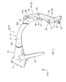
- Fig. 2 is a left side view of a main frame of the motorcycle.
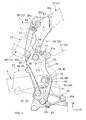
- Fig. 3 is a left side view of a rear portion of the main frame and component parts attached thereto.
- Fig. 4 is a right side view corresponding to Fig. 3.
- Fig. 5 is a rear view corresponding to Fig. 3.
- Fig. 6 is a perspective view, as viewed from the left front side, of the rear portion of the main frame.
- Fig. 7 is a perspective view, as viewed from the right front side, of the rear portion of the main frame.
- Fig. 8 is a perspective view, as viewed from the left front side, of left and right side plates attached to the rear portion of the main frame.
- Fig. 9 is a perspective view, as viewed from the right front side, of the left and right side plates.
- Now, an embodiment of the present invention will be described below referring to the drawings. Incidentally, the directions such as front, rear, left and right in the following description are to be understood as the directions with reference to the vehicle, unless otherwise specified. Besides, in the drawings, arrow FR indicates the front side of the vehicle, arrow LH indicates the left-hand side of the vehicle, and arrow UP indicates the upper side of the vehicle.
- As shown in Fig. 1, a
front wheel 2 of a motorcycle 1 is rotatably supported by lower end portions of a left-right pair of front forks 3, and an upper portion of the left and right front forks 3 is steerably supported pivotally on ahead pipe 6 at a front end portion of avehicle body frame 5 through a steering stem 4. Asteering bar handle 7 is mounted on the steering stem 4. Arear wheel 8 of the motorcycle 1 is rotatably supported on a rear end portion of aswing arm 9, and a front end portion of theswing arm 9 is vertically swingably supported pivotally on apivot portion 10 at a rear portion of thevehicle body frame 5. Arear cushion unit 11 is disposed between a front portion of theswing arm 9 and a rear portion of thevehicle body frame 5. - The
vehicle body frame 5 is composed mainly of amain frame 12 bridgingly provided between thehead pipe 6 and thepivot portion 10, and aseat frame 13 extending rearwards from a rear portion of themain frame 12.
Themain frame 12 is for suspending anengine 15 as a prime mover of the motorcycle 1, and is the so-called mono-backbone type frame in which a single framemain body 14 is extended rearwards from thehead pipe 6 through the center of vehicle width and on the upper side of theengine 15 and then bent downward to reach thepivot portion 10. On both sides of thepivot portion 10 of themain frame 12, a left-right pair ofside plates 16 are disposed on the left and right sides of that area. - The
engine 15 disposed on the inside of themain frame 12 is a parallel 4-cylinder engine having a crankshaft along the vehicle width direction (left-right direction), in whichcylinders 18 are erected on acrankcase 17, and athrottle body 20 is connected to an intake port at a rear portion of acylinder head 19 on eachcylinder 18. A rear portion of eachthrottle body 20 is connected to anair cleaner 21 disposed on the rear side thereof.Exhaust pipes 22 are led from exhaust ports at front portions of thecylinder heads 19, and are turned to the lower side of theengine 15 to be collected appropriately, before being connected to a silencer 23 rising up on the right side of theswing arm 9, for example. - A
drive sprocket 24 is disposed on the rear left side of theengine 15, and an endlessform drive chain 26 is wrapped around thedrive sprocket 24 and a drivensprocket 25 disposed on the left side of therear wheel 8.
Afuel tank 27 supported on themain frame 12 is disposed on the upper side of theengine 15, and aseat 28 supported on theseat frame 13 is disposed on the rear side of thefuel tank 27. Theseat 28 has a front half portion for the rider, and a rear half portion for the passenger.Step brackets 29 for supporting steps for the rider and the passenger are attached to rear portions of the left and right side plates. - The
main frame 12 has engine stays 30 branched from a front end portion of the framemain body 14 to the left and right sides and then extended downwards.
Lower end portion of the engine stays 30 are extended to positions on the front side of thecylinders 18, andfront engine hangers 31 fastened to the lower end portions are fastened to front portions of thecylinders 18 of theengine 15 to support the latter. Incidentally, aradiator 32 for cooling theengine 15 is disposed immediately on the front side of the engine stays 30. - Referring to Fig. 2 also, an intermediate portion in the front-rear direction of the frame
main body 14 is bent to be protuberant to the upper side, and a portion on the rear side thereof is bent to be protuberant to the rear upper side and then extended downwards to reach thepivot portion 10. The portion extended downwards will be described as a frame main bodyrear portion 35, including abent portion 35a on the rear side. - Here, the
main frame 12 is trisected into afront piece 36 including thehead pipe 6, the engine stays 30 and a front portion of the framemain body 14 formed as one body, acenter piece 37 including an intermediate portion of the framemain body 14 formed as one body, and arear piece 38 including the frame main bodyrear portion 35 formed as one body. - The
pieces front piece 36 and a front end portion of therear piece 38 are provided withmouthpiece portions center piece 37. In the condition where themouthpiece portions center piece 37, the open end portions are subjected to entire-circumference welding, whereby thepieces main frame 12. - The frame
main body 14 has a generally square hollow section at an intermediate portion thereof, is formed to be greater in vertical width on the front side at a front half portion thereof (see Fig. 5), and a front end portion thereof is integrated with a rear portion of thehead pipe 6 over the vertical range of the rear portion. - As shown in Figs. 3, 4 and 5, the frame main body
rear portion 35 is slightly inclined downwardly forwards, on the lower side of thebent portion 35a. In addition, the frame main bodyrear portion 35 is gradually broadened to the left and the right downwards from an intermediate portion of thebent portion 35a, and is then extended downwards while keeping the left-right width substantially constant. - The frame main body
rear portion 35 is formed on the lower front side to have a mount-like shape protuberant to the front side, and thepivot portion 10 is so provided as to penetrate through a peak portion of the mount-like shape in the left-right direction. Thepivot portion 10 has a configuration in which both side walls of the frame main bodyrear portion 35 are provided withpivot holes 39, and a collar extending along the left-right direction to range between thepivot holes 39 is formed in the frame main bodyrear portion 35. - Referring to Figs. 6 and 7 also, in the surroundings of the left and right outer sides of the left and
right pivot holes 39, there are provided annularpivot pedestal portions 40 slightly projecting to the left and right outer sides from outside surfaces of the frame main bodyrear portion 35.Pivot seat surfaces 41 orthogonal to the left-right direction are formed at the left and right outside ends of the pivotpedestal portions 40. - Left and right
arm pivot portions 42 formed individually at a front end portion of theswing arm 9 are adjacently disposed on the left and right outer sides of the left and right pivotpedestal portions 40. Collars (not shown) rotatable around an axis along the left-right direction are held on the left and right inner sides of thearm pivot portions 42, and the left and right inside ends of the collars abut on thepivot seat surfaces 41 of the pivotpedestal portions 40. - On both sides of a lower portion of the frame main body
rear portion 35, the left andright side plates 16 are disposed in the manner of sandwiching the lower portion from the left and right sides.
Referring to Figs. 8 and 9 also, the left andright side plates 16 each have a configuration in which a platemain body 45 is in a plate-like shape generally orthogonal to the left-right direction, and upper and lower plate-side bosses (means for adjusting a spacing) 46 and 47 are projected to the left-right inner side from the left-right inner side of upper and lower end portions of the platemain body 45. The tip ends of the upper and lower plate-side bosses rear portion 35, whereby a predetermined spacing is formed between the platemain body 45 and the frame main bodyrear portion 35. - Intermediate portions in the vertical direction of the left and
right side plates 16 are provided withpivot side holes 48 coaxial with thepivot portion 10. An annularplate pedestal portion 49 is provided in the surroundings of the left-right inner side of thepivot side hole 48, and aplate seat surface 50 orthogonal to the left-right direction is formed at the left-right inside end of theplate pedestal portion 49. The plate seat surfaces 50 are surfaces for abutting on the left-right outside ends of the above-mentioned collars in thearm pivot portion 42 at the front end portion of theswing arm 9. - A
pivot shaft 51 is passed through thepivot portion 10 of themain frame 12, the front end portion of theswing arm 9, and the intermediate portions in the vertical direction of the left andright side plates 16 in the manner of penetrating therethrough in the left-right direction. Thepivot shaft 51 is configured as a stepped bolt having an elongate shank portion, and is, for example, passed through thepivot portion 10, theswing arms 9 and theside plates 16 from the vehicle body left side, and anut 51a is screw engaged with and fastened to a right side portion of thepivot shaft 51 from the vehicle body right side. As a result, the above-mentioned collar in thearm pivot portion 42 is held between thepivot pedestal portion 40 and theplate pedestal portion 49, and a front end portion of theswing arm 9 is vertically swingably supported by thepivot portion 10 of themain frame 12. - Incidentally, the
swing arms 9 are configured to be asymmetric on the left and right sides, for convenience of layout of theexhaust pies 22, thedrive chain 26 and the like. To cope withsuch swing arms 9, for example, theplate pedestal portion 49 on the right side is provided projectingly to the left-right inner side from the inside surface of theside plate 16. On the other hand, theplate pedestal portion 49 on the left side is provided roughly on the same plane as the inside surface of theside plate 16. - A portion on the rear side of the
pivot portion 10 of the frame main bodyrear portion 35 is provided with left and right recessedportions 52 formed by recessing in spherical form the edge portions where the left and right outside surfaces meet the rear surface. In addition, the frame main bodyrear portion 35 is provided on the rear side of an upper portion thereof with a rear recessedportion 53 formed by recessing the relevant portion for securing a clearance between itself and therear cushion unit 11. At an upper portion of the rear recessedportion 53, there is provided asupport portion 54 for supporting an upper end portion of therear cushion unit 11. - The left and
right side plates 16 are aluminum diecast products, like thepieces main frame 12. Lightening is appropriately applied to the left-right inner side of the thick plate-like platemain body 45, leaving the outer wall and reinforcing ribs. - The upper and lower plate-
side bosses right side plates 16 are provided in their central portions with plate-side boss holes side bosses - On the other hand, at vertically intermediate portions and lower end portions on the front side of left-right outside portions of the frame main body
rear portion 35, there are provided upper and lower first bosses (first joint portions) 55 and 56 in which seat surfaces slightly projecting to the left-right outer sides are formed on both side walls of the frame main bodyrear portion 35. The upper and lowerfirst bosses first boss holes first bosses side bosses - The left and
right side plates 16 are disposed on both sides of a lower portion of the frame main bodyrear portion 35, and the plate-side boss surfaces 46b and 47b of the upper and lower plate-side bosses first bosses side boss holes side bosses first boss holes first bosses side bosses first bosses right side plates 16 and the frame main bodyrear portion 35 are integrally joined to each other. - In this case, between the outside portions of the frame main body
rear portion 35 and the inside portions of the left andright side plates 16, there are formed the above-mentioned spacings in amounts equal to the sums of the heights of projection of the upper and lowerfirst bosses rear portion 35 and the heights of projection of the upper and lower plate-side bosses right side plates 16. Front end portions of theswing arms 9 inserted into the spacings are each held between theside plate 16 and the frame main bodyrear portion 35. The lowerfirst boss 56 project to the left-right outer sides beyond the outside surfaces of the frame main bodyrear portion 35. - Incidentally, the outside surfaces of the left and
right side plates 16 constitute part of the outside surface of the vehicle body. Therefore,counterbore portions bolt head portion 51b of thepivot shaft 51 or thenut 51a to the left-right inner side are provided in the surroundings of the left-right outer sides of the upper and lower plate-side boss holes pivot side hole 48. - As shown in Figs. 3, 4 and 5, an
upper engine hanger 57 for supporting the upper side of a rear portion of thecrankcase 17 of theengine 15 and alower engine hanger 58 for supporting the lower side of the rear portion of thecrankcase 17 are attached to vertically intermediate portions and lower end portions (the vicinity of the upper and lowerfirst bosses 55, 56) on the front side of the left-right outside portions of the frame main bodyrear portion 35. Theengine 15 is suspended from themain frame 12 through theseengine hangers engine hanger 31. - Incidentally, the
main frame 12 is also the so-called diamond type frame in which a frame member on the lower side of theengine 15 is eliminated, and theengine 15 serves also as a reinforcing member of themain frame 12, whereby the position of theengine 15 is lowered, thereby contriving a lowering of the center of gravity, and the number of the frame members is reduced, thereby restraining increases in the weight and cost of the main frame. - The
upper engine hanger 57 has a generally triangular shape in side view, with a front end portion thereof as a portion to be fastened to thecrankcase 17, and with upper and lower parts of a rear end portion thereof as portions to be fastened to the frame main bodyrear portion 35. Theupper engine hanger 57 is formed by blanking into a predetermined shape a steel-made thick plate orthogonal to the left-right direction, for example. The vertices of the triangular shape are made to be afront fastening portion 57a provided with a bolt insertion hole, an upper-stagerear fastening portion 57b, and a lower-stagerear fastening portion 57c. In such anupper engine hanger 57, the same component parts can be used in common for the left and right portions of the vehicle body. - On the other hand, the
lower engine hanger 58 has a generally triangular shape in side view, with a front end portion thereof as a portion to be fastened to thecrankcase 17, and with upper end lower parts of a rear end portion thereof as portions to be fastened to the frame main bodyrear portion 35, similarly to the above-mentioned. Thelower engine hanger 58 is a casting cast from a steel, for example. The vertices of the triangular shape are made to be a boss-likefront fastening portion 58a provided with a bolt insertion hole along the left-right direction, an upper-stagerear fastening portion 58b, and a lower-stagerear fastening portion 58c. The left-right inside and outside surfaces of thefastening portions - Thus, with a rear portion of the
crankcase 17 supported by use of theengine hangers engine 15 asymmetric on the left and right sides can be suspended with a predetermined support rigidity. Incidentally, while thelower engine hanger 58 in this embodiment is a component part of mirror-image on the left and right sides for convenience of designing, the same component parts may be in common for the left and right sides of the vehicle body by modifying the shapes of them in side view, the shapes of thefastening portions - Referring to Figs. 8 and 9 also, upper-lower stage upper second bosses (second joint portions) 59, 60 adjacent to the upper front side and the lower front side of the upper
first boss 55 are provided at vertically intermediate portions on the front side of left and right outside portions of the frame main bodyrear portion 35. The uppersecond bosses rear portion 35, are provided in their central portions with uppersecond boss holes - Similarly, upper-lower stage lower second bosses (second joint portions) 61, 62 adjacent to the upper front side and the lower front side of the lower
first boss 56 are provided at lower end portions on the front side of the left and right outside portions of the frame main bodyrear portion 35. The lowersecond bosses rear portion 35, are provided in their central portions with lowersecond boss holes - In the condition where the inside surfaces of the
rear fastening portions upper engine hanger 57 abut on the second boss surfaces 59b and 60b of the uppersecond bosses rear fastening portions second boss holes second bosses rear fastening portions second bosses upper engine hanger 57 and the frame main bodyrear portion 35 are integrally joined to each other. - Similarly, in the condition where the inside surfaces of the
rear fastening portions lower engine hanger 58 abut on the second boss surfaces 61b and 62b of the lowersecond bosses rear fastening portions second boss holes second bosses rear fastening portions second bosses lower engine hanger 58 and the frame main bodyrear portion 35 are integrally joined to each other. - As shown in Figs. 1, 3 and 4, upper and lower front end portions of the
seat frame 13 are attached to upper end portions and vertically intermediate portions on the rear side of both side portions of the frame main bodyrear portion 35.
Theseat frame 13 has seat rails 65 extending in the front-rear direction slightly forwardly downwards for directly supporting theseat 28, andsub rails 66 disposed on the lower side of the seat rails 65 at an inclination slightly steeper than that of the seat rails 65. Rear portions of therails rails lower fastening portions rear portion 35. - On the other hand, upper and lower third bosses (third joint portions) 67, 68 projecting to the left-right outer sides are provided at upper end portions and vertically intermediate portions on the rear side of left and right outside portions of the frame main body
rear portion 35.
Referring to Fig. 5 also, the upperthird bosses 67 are formed with pedestals projecting to the left-right outer sides on both side walls of the frame main bodyrear portion 35. In addition, the lowerthird bosses 68 are formed with seat surfaces projecting to the left-right outer sides on both side walls of the frame main bodyrear portion 35. - Referring to Fig. 6 and 7 also, the upper and lower
third bosses third boss holes third bosses - In the condition where the inside surfaces of the upper and
lower fastening portions seat frame 13 abut on the third boss surfaces 67b and 68b of the upper and lowerthird bosses lower fastening portions third boss holes third bosses lower fastening portions third bosses seat frame 13 and the frame main bodyrear portion 35 are integrally joined to each other. - Here, the upper
first boss 55, the uppersecond bosses third boss 68 are proximate to one another, and the boss surfaces 55b, 59b, 60b, 68b of thebosses pivot portion 10 are each also provided on the plane Z.
Furthermore, in this embodiment, the boss surfaces 56b, 61b, 62b of the lowerfirst boss 56 and the lowersecond boss - Incidentally, in this embodiment, the first boss surfaces 56b of the left and right lower
first bosses 56 are provided at positions spaced by the same distance to the left and the right from the vehicle body center plane; on the other hand, the second boss surfaces 61b, 62b of the left and right lowersecond bosses second bosses lower engine hanger 58 is of mirror-image on the left and right sides. However, the lower second boss surfaces 61b, 62b of the left and right lowersecond bosses lower engine hanger 58, for example. - The boss surfaces 55b, 56b, 59b, 60b, 61b, 62b, 67b, 68b of the
bosses pivot portion 10 are formed by a mechanical working or the like by use of a milling machine or the like after the casting of therear piece 38, whereby they are enhanced in surface accuracy such as position, inclination, smoothness, etc. As a result of this, the relative positional accuracy of themain frame 12, theside plates 16, theswing arms 9, and theengine hangers swing arms 9 can be favorably supported by themain frame 12 and the left andright side plates 16, and a rear portion of theengine 15 can be favorably supported by theengine hangers - In forming the boss surfaces 55b, 56b, 59b, 60b, 61b, 62b, 67b, 68b and the pivot seat surfaces 41 as above-mentioned, if some of these surfaces, for example, some adjacent ones of these surfaces are provided on the same plane, they can be processed simultaneously and easily.
- As has been described above, the
vehicle body frame 5 for the motorcycle 1 in the above-described embodiment has a configuration in which themain frame 12 for suspending theengine 15 is extended rearwards from thehead pipe 6 through the center of vehicle width and then bent on the rear side of theengine 15 to extend down to thepivot portion 10, theswing arms 9 pivotally supported by thepivot portion 10 are held between the left-right pair ofside plates 16 disposed with themain frame 12 therebetween, theside plates 16 are each abutting on and joined to thefirst bosses main frame 12, and theengine hangers engine 15 on themain frame 12 abut on and are joined to thesecond bosses main frame 12. In thevehicle body frame 5, each of theside plates 16 is provided with the plate-side bosses main frame 12, and an appropriate combination of adjacent ones of the first boss surfaces 55b, 56b, abutting on theside plate 16, of thefirst bosses engine hangers second bosses - According to this configuration, even in the case of modifying the spacing between the
main frame 12 and theside plate 16 according to the swing arm width, it is possible to cope with the requirement by replacing the comparativelysmall side plate 16, and the need to modify the comparatively largemain frame 12 is eliminated, so that it is possible to suppress the cost required for modifying the swing arm width and to enhance the degree of freedom in vehicle body designing.
In addition, even in the case of applying mechanical working or the like to the first and second boss surfaces 55b, 56b, 59b, 60b, 61b, 62b so as to enhance the surface accuracy thereof for the purpose of enhancing the positional accuracy of theside plates 16 and theengine hangers vehicle body frame 5 can be reduced. - Besides, in the
vehicle body frame 5 for the motorcycle 1, theseat frame 13 extended rearwards from a rear portion of themain frame 12 abuts on and is joined to thethird bosses main frame 12, and an appropriate combination of adjacent ones of the third boss surfaces 67b, 68b, abutting on theseat frame 13, of thethird bosses vehicle body frame 5 can be reduced further. - Incidentally, the present invention is not limited to the above-described embodiment. For example, the plate-
side bosses main body 45, and may be integrally attached to the platemain body 45 by welding, screwing or the like. Furthermore, separate component parts corresponding to the plate-side bosses main frame 12 and eachside plate 16 may be integrally attached to at least one of themain frame 12 and theside plate 16 by welding, screwing or the like. According to this configuration, even in the case of modifying the spacing between themain frame 12 and theside plate 16 according to the swing arm width, it is possible to cope with the requirement easily and flexibly, so that the degree of freedom in vehicle body designing can be enhanced. Besides, where the separate component parts are provided so as to be replaceable, the just-mentioned effect is further enhanced.
The configuration in the above embodiment is merely an example, and the boss surfaces 55b, 56b, 59b, 60b, 61b, 62b, 67b, 68b may be formed on the same plane, in any combination thereof. Naturally, in addition, various modifications are possible within the scope of the gist of the present invention. - The invention provides a vehicle body frame for a motorcycle such that the spacing between a main frame and a side plate can be easily adjusted, and formation of joint surfaces, for abutting on the side plates and engine hangers, of the main frame by working can be easily carried out.
To achieve this,
eachside plate 16 is provided with upper and lower plate-side bosses side boss 46, of an upperfirst boss 55 of the main frame and surfaces, for abutting on anupper engine hanger 57, of uppersecond bosses side boss 47, of a lowerfirst boss 56 of the main frame and surfaces, for abutting on alower engine hanger 58, of lowersecond bosses
Claims (3)
- A vehicle body frame (5) for a motorcycle comprising:a main frame (12) for suspending an engine (15), said main frame (12) extended rearwards from a head pipe (6) through the center of vehicle width and bent on the rear side of said engine to extend down to a pivot portion (10);a swing arm (9) pivotally supported by said pivot portion (10), said swing arm (9) held between a left-right pair of side plates (16) disposed with said main frame (12) therebetween, said side plates (16) each abutting on and joined to a first joint portion (55, 56) provided in said main frame (12); andan engine hanger (57, 58) for supporting said engine (15) on said main frame (12), said engine hanger (57, 58) abutting on and joined to a second joint portion (59, 60, 61, 62) provided in said main frame (12),wherein each said side plate is provided with means (46, 47) for adjusting the spacing between itself and said main frame (12), and a first joint surface (55b, 56b), abutting on said side plate, of said first joint portion (55, 56) and a second joint surface (59b, 60b, 61b, 62b), abutting on said engine hanger (57, 58), of said second joint portion (59, 60, 61, 62) are provided on the same plane.
- The vehicle body frame for the motorcycle as set forth in claim 1, wherein a seat frame (13) extending rearwards from a rear portion of said main frame (12) abuts on and is joined to a third joint portion (67, 68) provided in said main frame (12), and a third joint surface (67b, 68b), abutting on said seat frame (13), of said third joint portion (67, 68) is provided on the same plane as said first and second joint surfaces.
- A vehicle body frame for a motorcycle comprising:a main frame (12) for suspending an engine (15), said main frame (12) extended rearwards from a head pipe (6) through the center of vehicle width and then bent on the rear side of said engine (15) to extend down to a pivot portion (10); anda swing arm (9) pivotally supported by said pivot portion (10), said swing arm (9) held between a left-right pair of side plates (16) disposed with said main frame (12) therebetween, and said side plates (16) each abutting on and joined to a first joint portion (55, 56) provided in said main frame (12),wherein at least one of said main frame (12) and each said side plate (16) is provided, as a separate member, with means (46, 47) for adjusting the spacing therebetween.
Applications Claiming Priority (1)
| Application Number | Priority Date | Filing Date | Title |
|---|---|---|---|
| JP2005316553A JP4628927B2 (en) | 2005-10-31 | 2005-10-31 | Motorcycle body frame |
Publications (3)
| Publication Number | Publication Date |
|---|---|
| EP1780108A2 true EP1780108A2 (en) | 2007-05-02 |
| EP1780108A3 EP1780108A3 (en) | 2010-01-13 |
| EP1780108B1 EP1780108B1 (en) | 2012-04-04 |
Family
ID=37744538
Family Applications (1)
| Application Number | Title | Priority Date | Filing Date |
|---|---|---|---|
| EP06019601A Not-in-force EP1780108B1 (en) | 2005-10-31 | 2006-09-19 | Vehicle body frame for motorcycle |
Country Status (4)
| Country | Link |
|---|---|
| US (1) | US7644796B2 (en) |
| EP (1) | EP1780108B1 (en) |
| JP (1) | JP4628927B2 (en) |
| ES (1) | ES2382046T3 (en) |
Cited By (1)
| Publication number | Priority date | Publication date | Assignee | Title |
|---|---|---|---|---|
| EP2077224A3 (en) * | 2007-12-28 | 2012-05-30 | Yamaha Hatsudoki Kabushiki Kaisha | Motorcycle |
Families Citing this family (12)
| Publication number | Priority date | Publication date | Assignee | Title |
|---|---|---|---|---|
| JP5112092B2 (en) * | 2008-01-31 | 2013-01-09 | 本田技研工業株式会社 | Rear frame mounting structure for motorcycles |
| JP5620810B2 (en) * | 2010-12-24 | 2014-11-05 | 川崎重工業株式会社 | Motorcycle body frame |
| JP5620809B2 (en) * | 2010-12-24 | 2014-11-05 | 川崎重工業株式会社 | Mounting structure for vehicle equipment in motorcycles |
| JP5800649B2 (en) * | 2011-09-26 | 2015-10-28 | 本田技研工業株式会社 | Body frame structure of saddle riding type vehicle |
| JP2014065465A (en) * | 2012-09-27 | 2014-04-17 | Honda Motor Co Ltd | Internal combustion engine for motorcycle |
| US20150158542A1 (en) * | 2012-12-09 | 2015-06-11 | Jesse G. James | Vehicle engine and transmission frame |
| JP6165012B2 (en) * | 2013-09-30 | 2017-07-19 | 本田技研工業株式会社 | Interlocking brake parts arrangement structure for saddle-ride type vehicles |
| US11578647B2 (en) | 2020-03-11 | 2023-02-14 | Arctic Cat Inc. | Engine |
| USD1043446S1 (en) * | 2022-06-17 | 2024-09-24 | Beijing Niu Technology Co., Ltd. | Motorcycle frame |
| USD1046693S1 (en) * | 2022-07-27 | 2024-10-15 | Beijing Niu Technology Co., Ltd. | Motorcycle frame |
| USD1044606S1 (en) * | 2022-07-27 | 2024-10-01 | Beijing Niu Technology Co., Ltd. | Motorcycle swing-arm |
| USD1062544S1 (en) * | 2023-10-10 | 2025-02-18 | Ruilifeng Industrial Technology (Shanghai) Co., Ltd | Frame for cycles or motorcycles |
Citations (1)
| Publication number | Priority date | Publication date | Assignee | Title |
|---|---|---|---|---|
| JPH0995279A (en) | 1995-09-29 | 1997-04-08 | Honda Motor Co Ltd | Motorcycle body frame |
Family Cites Families (16)
| Publication number | Priority date | Publication date | Assignee | Title |
|---|---|---|---|---|
| JPS594862Y2 (en) * | 1976-11-24 | 1984-02-13 | スズキ株式会社 | Two truck frames |
| JPS59213582A (en) * | 1983-05-18 | 1984-12-03 | 川崎重工業株式会社 | Frame division type motorcycle |
| JPS62103283A (en) * | 1985-10-30 | 1987-05-13 | 本田技研工業株式会社 | motorcycle |
| EP0322305B1 (en) * | 1987-12-21 | 1994-04-06 | Honda Giken Kogyo Kabushiki Kaisha | Body frame for motor-bicycle |
| JP3509143B2 (en) * | 1993-10-19 | 2004-03-22 | 本田技研工業株式会社 | Frame structure for motorcycles, etc. |
| JP3436330B2 (en) * | 1995-09-29 | 2003-08-11 | 本田技研工業株式会社 | Mounting structure at the rear of the engine of a motorcycle |
| US6098736A (en) * | 1997-12-31 | 2000-08-08 | Chrome Specialties, Inc. | Motorcycle swing arm |
| JP4008115B2 (en) * | 1998-09-11 | 2007-11-14 | 本田技研工業株式会社 | Body frame structure of motorcycle |
| JP4043614B2 (en) * | 1998-09-11 | 2008-02-06 | 本田技研工業株式会社 | Pivot structure of rear swing arm |
| JP3452847B2 (en) * | 1999-09-07 | 2003-10-06 | 川崎重工業株式会社 | Shaft support structure for motorcycle |
| JP2002326592A (en) * | 2001-05-02 | 2002-11-12 | Yamaha Motor Co Ltd | Motorcycle |
| JP4354135B2 (en) * | 2001-08-31 | 2009-10-28 | 本田技研工業株式会社 | Mounting structure for motorcycle fuel tank |
| JP4401680B2 (en) * | 2003-05-12 | 2010-01-20 | 川崎重工業株式会社 | Body frame of motorcycle |
| JP4303544B2 (en) * | 2003-09-09 | 2009-07-29 | 本田技研工業株式会社 | Small vehicle frame structure |
| JP4163585B2 (en) * | 2003-09-30 | 2008-10-08 | 本田技研工業株式会社 | Motorcycle body structure |
| JP4516497B2 (en) * | 2005-03-02 | 2010-08-04 | 本田技研工業株式会社 | Motorcycle body frame |
-
2005
- 2005-10-31 JP JP2005316553A patent/JP4628927B2/en not_active Expired - Fee Related
-
2006
- 2006-09-19 ES ES06019601T patent/ES2382046T3/en active Active
- 2006-09-19 EP EP06019601A patent/EP1780108B1/en not_active Not-in-force
- 2006-10-27 US US11/588,930 patent/US7644796B2/en active Active
Patent Citations (1)
| Publication number | Priority date | Publication date | Assignee | Title |
|---|---|---|---|---|
| JPH0995279A (en) | 1995-09-29 | 1997-04-08 | Honda Motor Co Ltd | Motorcycle body frame |
Cited By (2)
| Publication number | Priority date | Publication date | Assignee | Title |
|---|---|---|---|---|
| EP2077224A3 (en) * | 2007-12-28 | 2012-05-30 | Yamaha Hatsudoki Kabushiki Kaisha | Motorcycle |
| CN101468700B (en) * | 2007-12-28 | 2013-06-19 | 雅马哈发动机株式会社 | Motorcycle |
Also Published As
| Publication number | Publication date |
|---|---|
| US20070108722A1 (en) | 2007-05-17 |
| EP1780108B1 (en) | 2012-04-04 |
| ES2382046T3 (en) | 2012-06-04 |
| JP4628927B2 (en) | 2011-02-09 |
| EP1780108A3 (en) | 2010-01-13 |
| JP2007118865A (en) | 2007-05-17 |
| US7644796B2 (en) | 2010-01-12 |
Similar Documents
| Publication | Publication Date | Title |
|---|---|---|
| EP1780108B1 (en) | Vehicle body frame for motorcycle | |
| US7694985B2 (en) | Reinforced motorcycle frame | |
| US8016307B2 (en) | Fender supporting structure of two-wheeled motor vehicle | |
| US7849947B2 (en) | Motorcycle frame structure | |
| JP2000085674A (en) | Rear swing arm pivot structure | |
| EP1452432B1 (en) | Frame structure of a motorcycle | |
| JP2009090893A (en) | Saddle riding vehicle | |
| US8413757B2 (en) | Motorcycle engine | |
| JP5339603B2 (en) | Motorcycle | |
| JP4287683B2 (en) | Internal combustion engine | |
| JP5415363B2 (en) | Cylinder head structure of internal combustion engine | |
| JP2005280507A (en) | Motorcycle engine support device | |
| JP6704300B2 (en) | Motorcycle | |
| JP5481283B2 (en) | Cylinder head structure of internal combustion engine | |
| US9815521B2 (en) | Exhaust system of saddle-ride type vehicle | |
| JP5311650B2 (en) | Motorcycle | |
| JP6448692B2 (en) | On-vehicle structure of air-cooled internal combustion engine | |
| EP3533699B1 (en) | Engine hanger structure of a saddled vehicle | |
| JP2004249867A (en) | Structure of motorcycle | |
| JP3157692U (en) | Saddle riding vehicle | |
| JPH0686231B2 (en) | Body frame for motorcycles | |
| JP3157691U (en) | Saddle riding vehicle | |
| JP2010228739A (en) | Motorcycle | |
| JP2009090891A (en) | Saddle riding vehicle | |
| JP2021030816A (en) | Straddle-type vehicle with water-cooled engine |
Legal Events
| Date | Code | Title | Description |
|---|---|---|---|
| PUAI | Public reference made under article 153(3) epc to a published international application that has entered the european phase |
Free format text: ORIGINAL CODE: 0009012 |
|
| 17P | Request for examination filed |
Effective date: 20060919 |
|
| AK | Designated contracting states |
Kind code of ref document: A2 Designated state(s): AT BE BG CH CY CZ DE DK EE ES FI FR GB GR HU IE IS IT LI LT LU LV MC NL PL PT RO SE SI SK TR |
|
| AX | Request for extension of the european patent |
Extension state: AL BA HR MK YU |
|
| PUAL | Search report despatched |
Free format text: ORIGINAL CODE: 0009013 |
|
| AK | Designated contracting states |
Kind code of ref document: A3 Designated state(s): AT BE BG CH CY CZ DE DK EE ES FI FR GB GR HU IE IS IT LI LT LU LV MC NL PL PT RO SE SI SK TR |
|
| AX | Request for extension of the european patent |
Extension state: AL BA HR MK RS |
|
| 17Q | First examination report despatched |
Effective date: 20100701 |
|
| AKX | Designation fees paid |
Designated state(s): DE ES FR GB IT |
|
| GRAP | Despatch of communication of intention to grant a patent |
Free format text: ORIGINAL CODE: EPIDOSNIGR1 |
|
| GRAS | Grant fee paid |
Free format text: ORIGINAL CODE: EPIDOSNIGR3 |
|
| GRAA | (expected) grant |
Free format text: ORIGINAL CODE: 0009210 |
|
| AK | Designated contracting states |
Kind code of ref document: B1 Designated state(s): DE ES FR GB IT |
|
| REG | Reference to a national code |
Ref country code: GB Ref legal event code: FG4D |
|
| REG | Reference to a national code |
Ref country code: DE Ref legal event code: R096 Ref document number: 602006028572 Country of ref document: DE Effective date: 20120531 |
|
| REG | Reference to a national code |
Ref country code: ES Ref legal event code: FG2A Ref document number: 2382046 Country of ref document: ES Kind code of ref document: T3 Effective date: 20120604 |
|
| PLBE | No opposition filed within time limit |
Free format text: ORIGINAL CODE: 0009261 |
|
| STAA | Information on the status of an ep patent application or granted ep patent |
Free format text: STATUS: NO OPPOSITION FILED WITHIN TIME LIMIT |
|
| 26N | No opposition filed |
Effective date: 20130107 |
|
| REG | Reference to a national code |
Ref country code: DE Ref legal event code: R097 Ref document number: 602006028572 Country of ref document: DE Effective date: 20130107 |
|
| REG | Reference to a national code |
Ref country code: DE Ref legal event code: R084 Ref document number: 602006028572 Country of ref document: DE |
|
| REG | Reference to a national code |
Ref country code: GB Ref legal event code: 746 Effective date: 20150507 |
|
| REG | Reference to a national code |
Ref country code: DE Ref legal event code: R084 Ref document number: 602006028572 Country of ref document: DE Effective date: 20150505 |
|
| REG | Reference to a national code |
Ref country code: FR Ref legal event code: PLFP Year of fee payment: 11 |
|
| REG | Reference to a national code |
Ref country code: FR Ref legal event code: PLFP Year of fee payment: 12 |
|
| PGFP | Annual fee paid to national office [announced via postgrant information from national office to epo] |
Ref country code: CZ Payment date: 20170808 Year of fee payment: 12 |
|
| PGFP | Annual fee paid to national office [announced via postgrant information from national office to epo] |
Ref country code: ES Payment date: 20171002 Year of fee payment: 12 |
|
| REG | Reference to a national code |
Ref country code: FR Ref legal event code: PLFP Year of fee payment: 13 |
|
| PGFP | Annual fee paid to national office [announced via postgrant information from national office to epo] |
Ref country code: IT Payment date: 20180919 Year of fee payment: 13 |
|
| GBPC | Gb: european patent ceased through non-payment of renewal fee |
Effective date: 20180919 |
|
| PG25 | Lapsed in a contracting state [announced via postgrant information from national office to epo] |
Ref country code: GB Free format text: LAPSE BECAUSE OF NON-PAYMENT OF DUE FEES Effective date: 20180919 |
|
| REG | Reference to a national code |
Ref country code: ES Ref legal event code: FD2A Effective date: 20191031 |
|
| PG25 | Lapsed in a contracting state [announced via postgrant information from national office to epo] |
Ref country code: ES Free format text: LAPSE BECAUSE OF NON-PAYMENT OF DUE FEES Effective date: 20180920 |
|
| PG25 | Lapsed in a contracting state [announced via postgrant information from national office to epo] |
Ref country code: IT Free format text: LAPSE BECAUSE OF NON-PAYMENT OF DUE FEES Effective date: 20190919 |
|
| PG25 | Lapsed in a contracting state [announced via postgrant information from national office to epo] |
Ref country code: FR Free format text: LAPSE BECAUSE OF NON-PAYMENT OF DUE FEES Effective date: 20190930 |
|
| PGFP | Annual fee paid to national office [announced via postgrant information from national office to epo] |
Ref country code: DE Payment date: 20220609 Year of fee payment: 17 |
|
| REG | Reference to a national code |
Ref country code: DE Ref legal event code: R119 Ref document number: 602006028572 Country of ref document: DE |
|
| PG25 | Lapsed in a contracting state [announced via postgrant information from national office to epo] |
Ref country code: DE Free format text: LAPSE BECAUSE OF NON-PAYMENT OF DUE FEES Effective date: 20240403 |