EP1780072A2 - Adjustable lower seat for use with a stand and lean type backrest - Google Patents
Adjustable lower seat for use with a stand and lean type backrest Download PDFInfo
- Publication number
- EP1780072A2 EP1780072A2 EP06255455A EP06255455A EP1780072A2 EP 1780072 A2 EP1780072 A2 EP 1780072A2 EP 06255455 A EP06255455 A EP 06255455A EP 06255455 A EP06255455 A EP 06255455A EP 1780072 A2 EP1780072 A2 EP 1780072A2
- Authority
- EP
- European Patent Office
- Prior art keywords
- seat
- adjustor
- frame
- backrest
- operator
- Prior art date
- Legal status (The legal status is an assumption and is not a legal conclusion. Google has not performed a legal analysis and makes no representation as to the accuracy of the status listed.)
- Withdrawn
Links
Images



Classifications
-
- B—PERFORMING OPERATIONS; TRANSPORTING
- B60—VEHICLES IN GENERAL
- B60N—SEATS SPECIALLY ADAPTED FOR VEHICLES; VEHICLE PASSENGER ACCOMMODATION NOT OTHERWISE PROVIDED FOR
- B60N2/00—Seats specially adapted for vehicles; Arrangement or mounting of seats in vehicles
- B60N2/24—Seats specially adapted for vehicles; Arrangement or mounting of seats in vehicles for particular purposes or particular vehicles
- B60N2/30—Non-dismountable or dismountable seats storable in a non-use position, e.g. foldable spare seats
- B60N2/3038—Cushion movements
- B60N2/304—Cushion movements by rotation only
- B60N2/3045—Cushion movements by rotation only about transversal axis
- B60N2/305—Cushion movements by rotation only about transversal axis the cushion being hinged on the vehicle frame
-
- B—PERFORMING OPERATIONS; TRANSPORTING
- B60—VEHICLES IN GENERAL
- B60N—SEATS SPECIALLY ADAPTED FOR VEHICLES; VEHICLE PASSENGER ACCOMMODATION NOT OTHERWISE PROVIDED FOR
- B60N2/00—Seats specially adapted for vehicles; Arrangement or mounting of seats in vehicles
- B60N2/02—Seats specially adapted for vehicles; Arrangement or mounting of seats in vehicles the seat or part thereof being movable, e.g. adjustable
- B60N2/04—Seats specially adapted for vehicles; Arrangement or mounting of seats in vehicles the seat or part thereof being movable, e.g. adjustable the whole seat being movable
- B60N2/16—Seats specially adapted for vehicles; Arrangement or mounting of seats in vehicles the seat or part thereof being movable, e.g. adjustable the whole seat being movable height-adjustable
- B60N2/1605—Seats specially adapted for vehicles; Arrangement or mounting of seats in vehicles the seat or part thereof being movable, e.g. adjustable the whole seat being movable height-adjustable characterised by the cinematic
- B60N2/163—Slides only
-
- B—PERFORMING OPERATIONS; TRANSPORTING
- B60—VEHICLES IN GENERAL
- B60N—SEATS SPECIALLY ADAPTED FOR VEHICLES; VEHICLE PASSENGER ACCOMMODATION NOT OTHERWISE PROVIDED FOR
- B60N2/00—Seats specially adapted for vehicles; Arrangement or mounting of seats in vehicles
- B60N2/02—Seats specially adapted for vehicles; Arrangement or mounting of seats in vehicles the seat or part thereof being movable, e.g. adjustable
- B60N2/04—Seats specially adapted for vehicles; Arrangement or mounting of seats in vehicles the seat or part thereof being movable, e.g. adjustable the whole seat being movable
- B60N2/16—Seats specially adapted for vehicles; Arrangement or mounting of seats in vehicles the seat or part thereof being movable, e.g. adjustable the whole seat being movable height-adjustable
- B60N2/1635—Seats specially adapted for vehicles; Arrangement or mounting of seats in vehicles the seat or part thereof being movable, e.g. adjustable the whole seat being movable height-adjustable characterised by the drive mechanism
- B60N2/164—Linear actuator, e.g. screw mechanism
-
- B—PERFORMING OPERATIONS; TRANSPORTING
- B60—VEHICLES IN GENERAL
- B60N—SEATS SPECIALLY ADAPTED FOR VEHICLES; VEHICLE PASSENGER ACCOMMODATION NOT OTHERWISE PROVIDED FOR
- B60N2/00—Seats specially adapted for vehicles; Arrangement or mounting of seats in vehicles
- B60N2/02—Seats specially adapted for vehicles; Arrangement or mounting of seats in vehicles the seat or part thereof being movable, e.g. adjustable
- B60N2/04—Seats specially adapted for vehicles; Arrangement or mounting of seats in vehicles the seat or part thereof being movable, e.g. adjustable the whole seat being movable
- B60N2/16—Seats specially adapted for vehicles; Arrangement or mounting of seats in vehicles the seat or part thereof being movable, e.g. adjustable the whole seat being movable height-adjustable
- B60N2/18—Seats specially adapted for vehicles; Arrangement or mounting of seats in vehicles the seat or part thereof being movable, e.g. adjustable the whole seat being movable height-adjustable the front or the rear portion of the seat being adjustable, e.g. independently of each other
- B60N2/1807—Seats specially adapted for vehicles; Arrangement or mounting of seats in vehicles the seat or part thereof being movable, e.g. adjustable the whole seat being movable height-adjustable the front or the rear portion of the seat being adjustable, e.g. independently of each other characterised by the cinematic
- B60N2/1842—Seats specially adapted for vehicles; Arrangement or mounting of seats in vehicles the seat or part thereof being movable, e.g. adjustable the whole seat being movable height-adjustable the front or the rear portion of the seat being adjustable, e.g. independently of each other characterised by the cinematic pivoting about an axis located in the rear
-
- B—PERFORMING OPERATIONS; TRANSPORTING
- B60—VEHICLES IN GENERAL
- B60N—SEATS SPECIALLY ADAPTED FOR VEHICLES; VEHICLE PASSENGER ACCOMMODATION NOT OTHERWISE PROVIDED FOR
- B60N2/00—Seats specially adapted for vehicles; Arrangement or mounting of seats in vehicles
- B60N2/02—Seats specially adapted for vehicles; Arrangement or mounting of seats in vehicles the seat or part thereof being movable, e.g. adjustable
- B60N2/04—Seats specially adapted for vehicles; Arrangement or mounting of seats in vehicles the seat or part thereof being movable, e.g. adjustable the whole seat being movable
- B60N2/16—Seats specially adapted for vehicles; Arrangement or mounting of seats in vehicles the seat or part thereof being movable, e.g. adjustable the whole seat being movable height-adjustable
- B60N2/18—Seats specially adapted for vehicles; Arrangement or mounting of seats in vehicles the seat or part thereof being movable, e.g. adjustable the whole seat being movable height-adjustable the front or the rear portion of the seat being adjustable, e.g. independently of each other
- B60N2/185—Seats specially adapted for vehicles; Arrangement or mounting of seats in vehicles the seat or part thereof being movable, e.g. adjustable the whole seat being movable height-adjustable the front or the rear portion of the seat being adjustable, e.g. independently of each other characterised by the drive mechanism
- B60N2/1853—Linear actuator, e.g. screw mechanism
-
- B—PERFORMING OPERATIONS; TRANSPORTING
- B60—VEHICLES IN GENERAL
- B60N—SEATS SPECIALLY ADAPTED FOR VEHICLES; VEHICLE PASSENGER ACCOMMODATION NOT OTHERWISE PROVIDED FOR
- B60N2/00—Seats specially adapted for vehicles; Arrangement or mounting of seats in vehicles
- B60N2/24—Seats specially adapted for vehicles; Arrangement or mounting of seats in vehicles for particular purposes or particular vehicles
- B60N2002/247—Seats specially adapted for vehicles; Arrangement or mounting of seats in vehicles for particular purposes or particular vehicles to support passengers in a half-standing position
-
- B—PERFORMING OPERATIONS; TRANSPORTING
- B60—VEHICLES IN GENERAL
- B60N—SEATS SPECIALLY ADAPTED FOR VEHICLES; VEHICLE PASSENGER ACCOMMODATION NOT OTHERWISE PROVIDED FOR
- B60N2205/00—General mechanical or structural details
- B60N2205/40—Dual or redundant actuating means, e.g. backrest tilting can be actuated alternatively by a lever at the backrest or a lever in the luggage compartment
Definitions
- the present invention generally relates to seats, and, more particularly, to a stand up or lean seat for use with a vehicle.
- the present invention provides a seat that has a member which is configured to pivotally move between a substantially horizontal position and a substantially vertical position.
- the invention comprises, in one form thereof, a seat for use with a vehicle.
- the seat includes a member configured to pivot between a substantially horizontal position and a substantially vertical position.
- the seat further includes an adjustor configured to support the member at a plurality of positions between the substantially horizontal position and the substantially vertical position.
- the seat may also includes a frame pivotally coupled to the member, the adjustor being supported by the frame.
- the invention comprises, in yet another form thereof, a seat for use with a vehicle.
- the seat includes a member configured to pivot between a substantially horizontal position and a substantially vertical position.
- the seat also includes a frame and a backrest where the backrest is operably coupled to either the frame or the member.
- the seat further includes an adjustor operably coupled to the member and the frame where the adjustor is configured to support the member and the backrest at a plurality of positions including the substantially horizontal position.
- An advantage of the present invention is that the member allows the operator to select ergonomically comfortable support from multiple angular positions.
- the member is configured to take a substantially vertical position.
- the substantially vertical position allows the operator to assume a full standing position or leaning position while operating controls to the rear of the seat.
- seat 10 including member 12, adjustor 16 and frame 18 is shown.
- Member 12 is shown in a substantially horizontal position pivotally coupled to adjustor 16 and pivotally coupled to frame 18.
- seat 10 includes backrest / chest rest 14 and base 20, as shown in Fig. 1.
- Backrest / chest rest 14 is coupled to frame 18.
- Frame 18 is slidably coupled to base 20, as discussed in more detail below.
- Figure 1 also shows control lever 22, which is discussed in more detail below, coupled to frame 18.
- member 12 pivotally couple member 12 to each adjustor 16 and frame 18.
- Member 12 includes seat cushion portion 26 and seat frame 28.
- Seat frame 28 defines apertures 30 through which screws 32 or any other suitable fasteners couple seat frame 28 to seat cushion portion 26.
- seat frame 28 includes seat fastener 36 which pivotally couples member 12 to adjustor 16.
- adjustor 16 includes rod 40 and tube 42.
- Rod 40 defines a plurality of locking apertures 44 spaced linearly along the longitudinal axis of rod 40.
- Rod 40 defines fastener apertures 45 through which pin style locks 24 or any other suitable fasteners pivotally couple adjustor 16 to frame 18.
- Tube 42 defines member apertures 46 and includes spring loaded pull pin lock 48 or any other suitable fastener.
- Locking apertures 44 are configured to align with pin lock 48.
- Pin lock 48 is configured to be disposed within locking apertures 44.
- frame 18 includes base 50, seat fastener 52 and adjustor fastener 54.
- Seat fastener 52 and adjustor fastener 54 are coupled to base 50.
- Seat fastener 52 defines apertures 56 through which pin style locks 24 or any other suitable fasteners pivotally couple member 12 to frame 18.
- Adjustor fastener 54 defines adjustor apertures 58 through which pin style locks 24 or any other suitable fasteners pivotally couple adjustor 16 to frame 18.
- frame 18 includes backrest / chest rest fastener 60. Fastener 60 pivotally couples backrest / chest rest 14 to frame 18.
- member 12 is configured to pivot downward or upward along member bi-directional arrow 62 while adjustor 16 is configured to linearly expand or contract along adjustor bi-directional arrow 64.
- member 12 can pivotally rotate from a substantially horizontal position to a substantially vertical position.
- adjustor 16 linearly contracts along adjustor bi-directional arrow 64.
- adjustor 16 linearly expands along adjustor bi-directional arrow 64.
- adjustor 16 when disposing spring loaded pull pin lock 48 or any other suitable fastener into any locking aperture 44, adjustor 16 supports member 12. Depending upon the plurality of locking apertures 44 in which the pin lock 48 is disposed, the member 12 can take one of a plurality of pivotal positions including a substantially horizontal position and a substantially vertical position. While adjustor 16 illustrates pin lock 48 in locking apertures 44, alternative adjustment means are contemplated, such as hydraulic cylinders, a ratchet or winch adjustor, or pneumatic cylinders.
- seat cushion portion 26 is slightly angled up to keep the operator from sliding forward or off of seat 10.
- the seat cushion portion 26 has a contoured v-shaped form which allows the operator to select ergonomically comfortable support at multiple positions of member 12.
- Seat cushion portion 26 defines main contour 38 which is shaped to provide ergonomically comfortable seating for the operator.
- Seat cushion portion 26 also defines thigh contours 37 and 39. Thigh contours 37 and 39 are shaped to provide clearance for the legs of the operator.
- frame 18 is slidably coupled to base 20.
- Seat 10 is also configured to linearly adjust (for example, raise or lower) frame 18 in relation to base 20 along seat bi-directional arrow 80.
- the v-shaped form of member 12 also provides clearance between member 12 and backrest / chest rest 14 whether member 12 is in any position from substantially horizontal to substantially vertical.
- seat cushion portion 26 is also configured to provide maximum seat area without colliding with base 20 when member 12 is in a substantially vertical position.
- Backrest / Chest rest 14 is configured to support the chest of an operator.
- Backrest / chest rest 14 defines lower contour 66, main contour 68, side contours 70 and 72, side support contours 74 and 76 and arch contour 78.
- Contours 66, 68, 70, 72 and 78 are configured to provide ergonomically comfortable support whether the operator is facing towards or away from backrest / chest rest 14.
- Main contour 68 is configured to support the operator whether the operator is facing towards or away from backrest / chest rest 14.
- Main contour 68 and lower contour 66 are shaped to provide ergonomically comfortable support for the operator.
- Lower contour 66 and side contours 70 and 72 are configured to provide clearance between member 12 and backrest / chest rest 14 whether member 12 is in any position from substantially horizontal to substantially vertical.
- Side contours 70 and 72 are arcuate in form to provide additional support for operator whether the operator is facing towards or away from backrest / chest rest 14.
- side support contours 74 and 76 are configured to provide ergonomically comfortable support when the operator is facing towards backrest / chest rest 14. Side support contours 74 and 76 are also configured to provide clearance when the operator is facing towards backrest / chest rest 14 and / or operating control lever 22. Side support contours 74 and 76 are also shaped to provide ergonomically comfortable support for the elbows, arms or forearms of the operator. Arch contour 78 is configured to maximize ergonomically comfortable support when the operator is facing towards backrest / chest rest 14.
- Backrest / chest rest 14 is configured to pivot in relation to frame 18 in order to provide ergonomically comfortable support for an operator.
- frame 18 is slidably coupled to base 20.
- Frame 18, and therefore backrest / chest rest 14, is also configured to linearly adjust (for example, raise or lower) in relation to base 20 along seat bi-directional arrow 80.
- Arch contour 78 is also configured to maximize ergonomically comfortable support when backrest / chest rest 14 is in a plurality of pivotal positions in relation to frame 18.
Landscapes
- Engineering & Computer Science (AREA)
- Aviation & Aerospace Engineering (AREA)
- Transportation (AREA)
- Mechanical Engineering (AREA)
- Seats For Vehicles (AREA)
- Chairs For Special Purposes, Such As Reclining Chairs (AREA)
Abstract
Description
- The present invention generally relates to seats, and, more particularly, to a stand up or lean seat for use with a vehicle.
- The present invention provides a seat that has a member which is configured to pivotally move between a substantially horizontal position and a substantially vertical position.
- The invention comprises, in one form thereof, a seat for use with a vehicle. The seat includes a member configured to pivot between a substantially horizontal position and a substantially vertical position. The seat further includes an adjustor configured to support the member at a plurality of positions between the substantially horizontal position and the substantially vertical position.
- The seat may also includes a frame pivotally coupled to the member, the adjustor being supported by the frame.
- The invention comprises, in yet another form thereof, a seat for use with a vehicle. The seat includes a member configured to pivot between a substantially horizontal position and a substantially vertical position. The seat also includes a frame and a backrest where the backrest is operably coupled to either the frame or the member. The seat further includes an adjustor operably coupled to the member and the frame where the adjustor is configured to support the member and the backrest at a plurality of positions including the substantially horizontal position.
- An advantage of the present invention is that the member allows the operator to select ergonomically comfortable support from multiple angular positions.
- Another advantage is that the member is configured to take a substantially vertical position. The substantially vertical position allows the operator to assume a full standing position or leaning position while operating controls to the rear of the seat.
- The invention will now be further described by way of example with reference to the accompanying drawings in which:
- Figure 1 is a perspective view of a seat with a member in a substantially horizontal position.
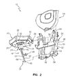
- Figure 2 is an exploded view of the seat of Figure 1.
- Figure 3 is a side perspective view of the seat of Figure 1.
- Figure 4 is another perspective view of the seat of Figure 1.
- Figure 5 is another perspective view of the seat of Figure 1 with the member in a substantially vertical position.
- Referring to Fig. 1,
seat 10 includingmember 12,adjustor 16 andframe 18 is shown.Member 12 is shown in a substantially horizontal position pivotally coupled toadjustor 16 and pivotally coupled toframe 18. Optionally,seat 10 includes backrest /chest rest 14 andbase 20, as shown in Fig. 1. Backrest /chest rest 14 is coupled toframe 18.Frame 18 is slidably coupled tobase 20, as discussed in more detail below. Figure 1 also showscontrol lever 22, which is discussed in more detail below, coupled toframe 18. - As illustrated in Fig. 2,
pin style locks 24 or any other suitable fasteners pivotally couplemember 12 to eachadjustor 16 andframe 18.Member 12 includesseat cushion portion 26 andseat frame 28.Seat frame 28 definesapertures 30 through which screws 32 or any other suitable fastenerscouple seat frame 28 toseat cushion portion 26. As shown in Fig. 2,seat frame 28 includesseat fastener 36 which pivotally couplesmember 12 toadjustor 16. - Still referring to Fig. 2,
adjustor 16 includesrod 40 andtube 42.Rod 40 defines a plurality of locking apertures 44 spaced linearly along the longitudinal axis ofrod 40.Rod 40 definesfastener apertures 45 through which pin style locks 24 or any other suitable fasteners pivotally coupleadjustor 16 to frame 18. Tube 42 definesmember apertures 46 and includes spring loadedpull pin lock 48 or any other suitable fastener. Locking apertures 44 are configured to align withpin lock 48.Pin lock 48 is configured to be disposed within locking apertures 44. - Still referring to Fig. 2,
frame 18 includesbase 50,seat fastener 52 andadjustor fastener 54.Seat fastener 52 andadjustor fastener 54 are coupled tobase 50.Seat fastener 52 definesapertures 56 through which pin style locks 24 or any other suitable fasteners pivotally couplemember 12 toframe 18.Adjustor fastener 54 definesadjustor apertures 58 through which pin style locks 24 or any other suitable fasteners pivotally coupleadjustor 16 to frame 18. Optionally,frame 18 includes backrest /chest rest fastener 60. Fastener 60 pivotally couples backrest /chest rest 14 to frame 18. - As illustrated in Fig. 3,
member 12 is configured to pivot downward or upward along member bi-directionalarrow 62 whileadjustor 16 is configured to linearly expand or contract along adjustor bi-directionalarrow 64. When removing the spring loadedpull pin lock 48 or any other suitable fastener from any locking aperture 44,member 12 can pivotally rotate from a substantially horizontal position to a substantially vertical position. Whenmember 12 pivotally rotates downward along member bi-directionalarrow 62,adjustor 16 linearly contracts along adjustor bi-directionalarrow 64. Whenmember 12 pivotally rotates upward,adjustor 16 linearly expands along adjustor bi-directionalarrow 64. - Still referring to Fig. 3, when disposing spring loaded
pull pin lock 48 or any other suitable fastener into any locking aperture 44,adjustor 16 supportsmember 12. Depending upon the plurality of locking apertures 44 in which thepin lock 48 is disposed, themember 12 can take one of a plurality of pivotal positions including a substantially horizontal position and a substantially vertical position. Whileadjustor 16 illustratespin lock 48 in locking apertures 44, alternative adjustment means are contemplated, such as hydraulic cylinders, a ratchet or winch adjustor, or pneumatic cylinders. - As illustrated in Figs. 3 and 4,
seat cushion portion 26 is slightly angled up to keep the operator from sliding forward or off ofseat 10. As shown in Fig. 4, theseat cushion portion 26 has a contoured v-shaped form which allows the operator to select ergonomically comfortable support at multiple positions ofmember 12.Seat cushion portion 26 definesmain contour 38 which is shaped to provide ergonomically comfortable seating for the operator.Seat cushion portion 26 also definesthigh contours Thigh contours frame 18 is slidably coupled tobase 20. Seat 10 is also configured to linearly adjust (for example, raise or lower)frame 18 in relation tobase 20 along seat bi-directionalarrow 80. - Referring to Figs. 4 and 5, the v-shaped form of
member 12 also provides clearance betweenmember 12 and backrest /chest rest 14 whethermember 12 is in any position from substantially horizontal to substantially vertical. As illustrated in Fig. 5,seat cushion portion 26 is also configured to provide maximum seat area without colliding withbase 20 whenmember 12 is in a substantially vertical position. - Still referring to Fig. 5, when
member 12 is in a substantially vertical position, operator may face or lean againstseat 10 while operating control lever 22. Backrest /Chest rest 14 is configured to support the chest of an operator. Backrest /chest rest 14 defineslower contour 66,main contour 68,side contours side support contours 74 and 76 andarch contour 78.Contours chest rest 14.Main contour 68 is configured to support the operator whether the operator is facing towards or away from backrest /chest rest 14.Main contour 68 andlower contour 66 are shaped to provide ergonomically comfortable support for the operator.Lower contour 66 andside contours member 12 and backrest /chest rest 14 whethermember 12 is in any position from substantially horizontal to substantially vertical.Side contours chest rest 14. - Yet still referring to Fig. 5,
side support contours 74 and 76 are configured to provide ergonomically comfortable support when the operator is facing towards backrest /chest rest 14.Side support contours 74 and 76 are also configured to provide clearance when the operator is facing towards backrest /chest rest 14 and / or operatingcontrol lever 22.Side support contours 74 and 76 are also shaped to provide ergonomically comfortable support for the elbows, arms or forearms of the operator.Arch contour 78 is configured to maximize ergonomically comfortable support when the operator is facing towards backrest /chest rest 14. - Backrest /
chest rest 14 is configured to pivot in relation to frame 18 in order to provide ergonomically comfortable support for an operator. As previously mentioned,frame 18 is slidably coupled tobase 20.Frame 18, and therefore backrest /chest rest 14, is also configured to linearly adjust (for example, raise or lower) in relation tobase 20 along seatbi-directional arrow 80.Arch contour 78 is also configured to maximize ergonomically comfortable support when backrest /chest rest 14 is in a plurality of pivotal positions in relation to frame 18.
Claims (17)
- A seat for use with a vehicle comprising a member configured to pivot between a substantially horizontal position and a substantially vertical position, and an adjustor configured to support the member at a plurality of positions between the substantially horizontal position and the substantially vertical position.
- The seat of claim 1, further comprising a frame pivotally coupled to the member and the adjustor, and a pivoting backrest coupled to the frame, the backrest configured to provide support to an operator.
- The seat of claim 1, further comprising a frame pivotally coupled to the member, and the adjustor being supported by the frame.
- The seat of claim 3 further comprising a backrest supported by the frame.
- The seat of claim 4, wherein the backrest is configured to support an operator.
- The seat of any preceding claim, wherein the adjustor converts pivotal movement of the member into linear movement of the adjustor.
- A seat for use with a vehicle comprising a member configured to pivot between a substantially horizontal position and a substantially vertical position, a frame, a backrest coupled to either the frame or the member, and an adjustor operably coupled to the member and the frame, the adjustor configured to support the member at a plurality of positions including the substantially horizontal position and the substantially vertical position.
- The seat of claim 7 wherein the adjustor includes a rod and a tube, where the rod defines a plurality of holes spaced apart along the longitudinal axis of the rod, where the tub includes a pin lock configured to lock into any one of the plurality of holes.
- The seat of claim 8, wherein the pin lock is a spring loaded pull pin lock.
- The seat of either claim 8 or claim 9, wherein the adjustor converts pivotal movement of the member into linear movement of the tube.
- The seat of any one of claims 7 to 10, wherein the member is pivotally coupled to the frame.
- The seat of any one of claims 7 to 11, wherein the adjustor is pivotally coupled to the frame.
- The seat of any one of claims 2 to 12, wherein the backrest is used as a chest rest.
- The seat of any preceding claim wherein the adjustor is configured to allow an operator to select from the plurality of positions.
- The seat of any preceding claim, wherein the adjustor is a hydraulic cylinder or a ratchet or winch or a pneumatic cylinder.
- The seat of any preceding claim wherein the member includes a substantially v-shaped seat cushion.
- The seat of any preceding claim further comprising a base slidably coupled to the frame.
Applications Claiming Priority (2)
| Application Number | Priority Date | Filing Date | Title |
|---|---|---|---|
| US73175305P | 2005-10-31 | 2005-10-31 | |
| US11/467,589 US7914078B2 (en) | 2005-10-31 | 2006-08-28 | Adjustable lower seat for use with a stand and lean type backrest |
Publications (2)
| Publication Number | Publication Date |
|---|---|
| EP1780072A2 true EP1780072A2 (en) | 2007-05-02 |
| EP1780072A3 EP1780072A3 (en) | 2007-11-07 |
Family
ID=37738756
Family Applications (1)
| Application Number | Title | Priority Date | Filing Date |
|---|---|---|---|
| EP06255455A Withdrawn EP1780072A3 (en) | 2005-10-31 | 2006-10-24 | Adjustable lower seat for use with a stand and lean type backrest |
Country Status (3)
| Country | Link |
|---|---|
| US (1) | US7914078B2 (en) |
| EP (1) | EP1780072A3 (en) |
| JP (1) | JP2007126133A (en) |
Cited By (3)
| Publication number | Priority date | Publication date | Assignee | Title |
|---|---|---|---|---|
| FR2947774A1 (en) * | 2009-07-13 | 2011-01-14 | Peugeot Citroen Automobiles Sa | DEVICE FOR DEPLOYING A VEHICLE SEAT WITH A SEAT-UP MECHANISM |
| US9221361B1 (en) * | 2013-11-27 | 2015-12-29 | Armorworks Enterprises LLC | Spring assisted energy attenuating seating system |
| EP3266648A1 (en) * | 2016-07-04 | 2018-01-10 | BRUSA Koltuk ve Ic Trim Teknolojileri Sanayi ve Tiaret A.S. | Seat having foldable structure for vehicles |
Families Citing this family (20)
| Publication number | Priority date | Publication date | Assignee | Title |
|---|---|---|---|---|
| US8132838B2 (en) * | 2008-10-06 | 2012-03-13 | Black Mountain Industries, Inc. | Soldier support system in a vehicle |
| US8011730B2 (en) * | 2008-10-06 | 2011-09-06 | Black Mountain Industries, Inc. | Soldier platform system |
| US8757721B2 (en) | 2008-10-06 | 2014-06-24 | Black Mountain Industries, Inc. | Soldier platform system |
| US8657247B2 (en) | 2008-10-06 | 2014-02-25 | Black Mountain Industries, Inc. | Ratchet platform |
| US8998286B2 (en) | 2008-10-06 | 2015-04-07 | Black Mountain Industries, Inc. | Soldier support system in a vehicle |
| US8919882B2 (en) | 2008-10-06 | 2014-12-30 | Black Mountain Industries, Inc. | Soldier platform system |
| US8590853B2 (en) * | 2008-10-06 | 2013-11-26 | Black Mountain Industries, Inc. | Ratchet platform |
| USD598223S1 (en) | 2008-11-13 | 2009-08-18 | The Raymond Corporation | Vehicle seat |
| USD653882S1 (en) | 2008-11-13 | 2012-02-14 | The Raymond Corporation | Vehicle seat with bump |
| GB0903115D0 (en) * | 2009-02-25 | 2009-04-08 | Agco Sa | Foldaway passenger seat for utility vehicle |
| EP2630004A1 (en) | 2010-10-19 | 2013-08-28 | BAE Systems PLC | Vehicle seat |
| US9321378B2 (en) * | 2010-10-19 | 2016-04-26 | Bae Systems Plc | Vehicle seat |
| US9434278B2 (en) | 2012-05-18 | 2016-09-06 | Black Mountain Industries, Inc. | Wall rail platform and release system |
| JP6113115B2 (en) * | 2014-06-23 | 2017-04-12 | 株式会社クボタ | Sheet device |
| JP1536530S (en) * | 2014-09-18 | 2018-10-22 | ||
| JP1534328S (en) | 2014-09-18 | 2018-09-18 | ||
| US11291307B2 (en) * | 2018-04-20 | 2022-04-05 | Ergotech Solutions, Inc. | Body support |
| AU2022203994A1 (en) | 2021-06-11 | 2023-01-05 | The Raymond Corporation | Back pad assembly for a material handling vehicle |
| USD1091208S1 (en) | 2022-06-10 | 2025-09-02 | The Raymond Corporation | Back pad |
| US20240253789A1 (en) * | 2023-01-27 | 2024-08-01 | The Boeing Company | Transformable seat systems and methods for an internal cabin of an aircraft |
Family Cites Families (18)
| Publication number | Priority date | Publication date | Assignee | Title |
|---|---|---|---|---|
| US1664958A (en) * | 1925-02-09 | 1928-04-03 | Earl A Zeiser | Infant's auto carrier |
| US3131964A (en) * | 1962-11-13 | 1964-05-05 | Budd Co | Folding seat arrangement |
| US3744843A (en) * | 1969-01-17 | 1973-07-10 | American Seating Co | Vehicle chair unit |
| US4632457A (en) * | 1985-10-15 | 1986-12-30 | Seats Incorporated | Collapsible seat |
| US4787675A (en) * | 1986-02-19 | 1988-11-29 | Mcleod Michael E | Adjustable seat to support an occupant at a constant height |
| GB2209276B (en) * | 1987-09-04 | 1990-07-25 | Brian Chanin Limited | Portable folding seat |
| US5265689A (en) * | 1991-01-14 | 1993-11-30 | Kauffmann Ricardo M | Prosthetic device for lifting and lowering a person thereon |
| US5364151A (en) * | 1993-04-21 | 1994-11-15 | Mack Trucks, Inc. | Adjustable seat apparatus for utility vehicle |
| US5775655A (en) * | 1996-09-23 | 1998-07-07 | Schmeets; Harold H. | Colllapsible and adjustable support means for attachment to a building structure |
| ATE211713T1 (en) * | 1997-08-28 | 2002-01-15 | Crown Equip Corp | DRIVER'S STATION FOR INDUSTRIAL TRUCK WITH SEATING ADJUSTABLE IN THREE POSITIONS |
| US6224153B1 (en) * | 1999-07-08 | 2001-05-01 | Senior Industries, Inc. | Folding seat assembly |
| US6527341B1 (en) * | 2000-06-16 | 2003-03-04 | Genmar Ip Llc | Hinge assembly for folding seat |
| JP2003019055A (en) * | 2001-07-11 | 2003-01-21 | Komura Seisakusho:Kk | Lifting chair |
| US6692076B1 (en) * | 2002-02-04 | 2004-02-17 | Peter J. Burer | Bolster chair with foldable seat that is vertically adjustable when folded into a vertical position |
| US7047716B2 (en) * | 2003-02-28 | 2006-05-23 | Deere & Company | Convertible support |
| US6729685B1 (en) * | 2003-04-29 | 2004-05-04 | Sonny Ebalobor | Foldable wall supported seat |
| USD536889S1 (en) * | 2005-07-12 | 2007-02-20 | Dlp Limited | Foldable shower seat |
| US7367616B2 (en) * | 2005-08-12 | 2008-05-06 | Triton Boat Company, L.P. | Folding boat seat |
-
2006
- 2006-08-28 US US11/467,589 patent/US7914078B2/en not_active Expired - Fee Related
- 2006-10-24 EP EP06255455A patent/EP1780072A3/en not_active Withdrawn
- 2006-10-24 JP JP2006288890A patent/JP2007126133A/en active Pending
Cited By (4)
| Publication number | Priority date | Publication date | Assignee | Title |
|---|---|---|---|---|
| FR2947774A1 (en) * | 2009-07-13 | 2011-01-14 | Peugeot Citroen Automobiles Sa | DEVICE FOR DEPLOYING A VEHICLE SEAT WITH A SEAT-UP MECHANISM |
| WO2011007069A1 (en) * | 2009-07-13 | 2011-01-20 | Peugeot Citroën Automobiles SA | Device for deploying a vehicle seat with a seat-portion-raising mechanism |
| US9221361B1 (en) * | 2013-11-27 | 2015-12-29 | Armorworks Enterprises LLC | Spring assisted energy attenuating seating system |
| EP3266648A1 (en) * | 2016-07-04 | 2018-01-10 | BRUSA Koltuk ve Ic Trim Teknolojileri Sanayi ve Tiaret A.S. | Seat having foldable structure for vehicles |
Also Published As
| Publication number | Publication date |
|---|---|
| US7914078B2 (en) | 2011-03-29 |
| EP1780072A3 (en) | 2007-11-07 |
| US20070096526A1 (en) | 2007-05-03 |
| JP2007126133A (en) | 2007-05-24 |
Similar Documents
| Publication | Publication Date | Title |
|---|---|---|
| US7914078B2 (en) | Adjustable lower seat for use with a stand and lean type backrest | |
| US5692802A (en) | Vehicle seat with adjustable seat part length | |
| US4877291A (en) | Reclining chair | |
| US20080084102A1 (en) | Seating furniture item, in particular office chair | |
| CN100427012C (en) | Seat assembly and method for self-adjusting seat assembly by user | |
| US8272692B1 (en) | Office chair having tiltable seat and back | |
| US8851563B2 (en) | Furniture fitting system | |
| US7946651B2 (en) | Mechanism for adjusting the inclination of backrests in chairs and arm-chairs, particularly in office chairs | |
| EP0934716A3 (en) | Mechanism for chair | |
| IT9047711A1 (en) | VEHICLE SEAT WITH ADJUSTABLE THIGH SUPPORT. | |
| JP2000501969A (en) | Adjuster for chair | |
| US6578918B1 (en) | Chair | |
| US6213551B1 (en) | Chair locking mechanism | |
| US7147282B2 (en) | Chair with backrest depth adjustment mechanism | |
| JP2020058758A (en) | Chair and manufacturing method of the same | |
| US9144316B1 (en) | Programmer's chair | |
| US7823976B2 (en) | Chair | |
| US9609953B2 (en) | Spring back hinge with or without spring lock mechanism | |
| EP2389840B1 (en) | Chair adjustment structure | |
| EP0443002A1 (en) | Improved adjustable seating assembly | |
| CN101951812B (en) | Chair | |
| US7431397B2 (en) | Chair | |
| KR102303651B1 (en) | Partially adjustable structure for chair seat | |
| JP2003310377A (en) | Gas spring for chair | |
| JP3637731B2 (en) | Chair armrest device |
Legal Events
| Date | Code | Title | Description |
|---|---|---|---|
| PUAI | Public reference made under article 153(3) epc to a published international application that has entered the european phase |
Free format text: ORIGINAL CODE: 0009012 |
|
| AK | Designated contracting states |
Kind code of ref document: A2 Designated state(s): AT BE BG CH CY CZ DE DK EE ES FI FR GB GR HU IE IS IT LI LT LU LV MC NL PL PT RO SE SI SK TR |
|
| AX | Request for extension of the european patent |
Extension state: AL BA HR MK YU |
|
| PUAL | Search report despatched |
Free format text: ORIGINAL CODE: 0009013 |
|
| AK | Designated contracting states |
Kind code of ref document: A3 Designated state(s): AT BE BG CH CY CZ DE DK EE ES FI FR GB GR HU IE IS IT LI LT LU LV MC NL PL PT RO SE SI SK TR |
|
| AX | Request for extension of the european patent |
Extension state: AL BA HR MK YU |
|
| 17P | Request for examination filed |
Effective date: 20080507 |
|
| 17Q | First examination report despatched |
Effective date: 20080605 |
|
| AKX | Designation fees paid |
Designated state(s): GB IT |
|
| REG | Reference to a national code |
Ref country code: DE Ref legal event code: 8566 |
|
| STAA | Information on the status of an ep patent application or granted ep patent |
Free format text: STATUS: THE APPLICATION IS DEEMED TO BE WITHDRAWN |
|
| 18D | Application deemed to be withdrawn |
Effective date: 20081016 |