EP1780049A1 - Bicycle hub - Google Patents
Bicycle hub Download PDFInfo
- Publication number
- EP1780049A1 EP1780049A1 EP06022079A EP06022079A EP1780049A1 EP 1780049 A1 EP1780049 A1 EP 1780049A1 EP 06022079 A EP06022079 A EP 06022079A EP 06022079 A EP06022079 A EP 06022079A EP 1780049 A1 EP1780049 A1 EP 1780049A1
- Authority
- EP
- European Patent Office
- Prior art keywords
- hub
- inner tube
- axle
- free end
- bearing
- Prior art date
- Legal status (The legal status is an assumption and is not a legal conclusion. Google has not performed a legal analysis and makes no representation as to the accuracy of the status listed.)
- Granted
Links
Images



Classifications
-
- B—PERFORMING OPERATIONS; TRANSPORTING
- B60—VEHICLES IN GENERAL
- B60B—VEHICLE WHEELS; CASTORS; AXLES FOR WHEELS OR CASTORS; INCREASING WHEEL ADHESION
- B60B27/00—Hubs
- B60B27/0073—Hubs characterised by sealing means
-
- B—PERFORMING OPERATIONS; TRANSPORTING
- B60—VEHICLES IN GENERAL
- B60B—VEHICLE WHEELS; CASTORS; AXLES FOR WHEELS OR CASTORS; INCREASING WHEEL ADHESION
- B60B27/00—Hubs
- B60B27/0005—Hubs with ball bearings
-
- B—PERFORMING OPERATIONS; TRANSPORTING
- B60—VEHICLES IN GENERAL
- B60B—VEHICLE WHEELS; CASTORS; AXLES FOR WHEELS OR CASTORS; INCREASING WHEEL ADHESION
- B60B27/00—Hubs
- B60B27/02—Hubs adapted to be rotatably arranged on axle
- B60B27/023—Hubs adapted to be rotatably arranged on axle specially adapted for bicycles
Definitions
- the present invention generally relates to a bicycle hub of a bicycle wheel that is mounted to a bicycle frame. More specifically, the present invention relates to a bicycle hub with an inner tubular structure for substantially preventing the bearing grease from leaking towards the center of the hub.
- Bicycling is becoming an increasingly more popular form of recreation as well as a means of transportation. Moreover, bicycling has become a very popular competitive sport for both amateurs and professionals. Whether the bicycle is used for recreation, transportation or competition, the bicycle industry is constantly improving the various components of the bicycle as well. One component that has been extensively redesigned is the hub of the bicycle.
- bicycle hubs have a hub shaft or axle mounted in a non-rotatable manner to a rear part of the bicycle frame and a hub shell or body mounted in a rotatable manner to the hub axle by a pair of bearing assemblies.
- the hub shell or body is freely rotatable on the hub axle in both directions.
- one side of the rear hub is provided with a drive body or driving cylinder that is mounted in a freely rotatable manner to one end of the hub shell, and a one-way clutch arranged between the driving cylinder and the hub shell to transmit rotation from the driving cylinder to the hub shell in one direction.
- the driving cylinder is configured and arranged to have a plurality of sprockets mounted to a radially outward-facing surface of the driving cylinder such that the sprockets can neither rotate nor move axially with respect to the driving cylinder.
- the driving cylinders of these types of rear hubs only rotate in one direction on their hub axles.
- This conventional bicycle hub is installed in the central portion of a wheel of a bicycle with spokes extending from the hub to a rim.
- This conventional bicycle hub has a hub axle, a hub body and a pair of bearings.
- the hub axle is non-rotatably mounted to a frame of the bicycle (for example, to a front-fork).
- the hub body is coaxially coupled to the hub axle so that the hub body is disposed radially outwardly with respect to the hub axle.
- the bearings are configured and arranged to support the hub body so that the hub body can freely rotate around the hub axle.
- the outer peripheral surface of the hub axle includes a pair of male screw sections in axial ends thereof so that the hub is mounted to the frame by a pair of nuts that are screw on axial ends of the male screw of the hub axle.
- the bearings are angular-type bearings. Each of the bearings is provided with an outer ring or cup, an inner ring or cone, and a plurality of rolling components (balls).
- the outer ring is disposed along an inner peripheral surface of the hub body and includes a ball receiving surface.
- the inner ring is screwed into the hub axle and includes a ball pushing surface.
- the rolling components are disposed between the outer ring and the inner ring at predetermined intervals in a circumferential direction of the hub.
- each of the bearings is filled with grease in order to make the rotation of the bearings smooth.
- the ball receiving surface of the outer ring is arranged as a concaved surface that faces toward a generally axial outward direction of the hub axle.
- the ball pushing surface of the inner ring is arranged as a concaved surface that faces toward a generally axial inward direction of the hub axle.
- the angular-type ball bearing installed on the hub is designed to maintain a certain degree of clearance or gap between the radial innermost peripheral surface of the outer ring and an outer peripheral surface of the hub axle.
- a sealing component is coupled to an outer axial direction of the bearing. Therefore, the bearing is designed so that the grease does not leak towards the outer axial direction of the bearing.
- the grease filled within the bearing occasionally leaks towards the inner axial direction of the bearing.
- the hub includes the male screw section is formed in the same screw direction along the entire surface of the outer peripheral surface of the hub axle, the male screw acts like a pump due to the rotation of the wheel (i.e., the rotation of the outer ring of the bearing) relative to the hub axle. Consequently, the grease flows out from the bearing toward the inner axial direction of the hub axle.
- the male screw is a right-handed screw
- the bearing on the right side as viewed from the rear side of the bicycle
- the grease tends to flow out toward the inner axial direction of the hub axle.
- the grease tends to travel toward a relatively larger space behind the outer ring and retained in that space due to the centrifugal force.
- the amount of the grease in the bearing becomes insufficient, and rotation of the wheel deteriorates.
- One object of the present invention is to provide to a hub with an inner tubular structure that substantially prevent grease from flowing out from the bearings toward the inner axial direction.
- Another object of the present invention is to provide to a hub with an inner tubular structure that can be used with hubs having different axial lengths between the bearings.
- Another object of the present invention is to provide to a hub with an inner tubular structure that is relatively easy to assembly.
- a bicycle hub that comprises a hub axle, a hub body, a first bearing, a second bearing and an inner tubular structure.
- the hub axle has a first axle end and a second axle end.
- the hub body has a first body end and a second body end with the hub body being coaxially disposed about the hub axle and rotatable with respect to the hub axle.
- the first bearing is disposed between the first body end of the hub body and the first end of the hub axle.
- the second bearing is disposed between the second body end of the hub body and the second axle end of the hub axle.
- the inner tubular structure includes a first inner tube and a second inner tube.
- the first inner tube has a first fixed portion fixedly secured relative to the first body end adjacent to the first bearing and a first free end portion.
- the second inner tube has a second fixed portion fixedly secured relative to the second body end adjacent to the second bearing and a second free end portion.
- the first and second free end portions are telescopically arranged.
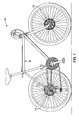
- Figure 1 is an overall right side elevational view of a bicycle provided with front and rear hubs having inner tubular structures in accordance with a first embodiment of the present invention
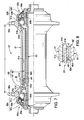
- Figure 2 is a partial cross sectional view of the front hub provided with the inner tubular structure in accordance with the first embodiment of the present invention
- Figure 3 is an enlarged partial cross sectional view of the telescoping area of the inner tubular structure that is circled in dashed lines in Figure 2;
- Figure 4 is a partial cross sectional view of a modified hub provided with the inner tubular structure in accordance with the first embodiment of the present invention
- Figure 5 is a partial cross sectional view of the first or left inner tube that is used in both the front and rear hubs in accordance with the first embodiment of the present invention
- Figure 6 is a partial cross sectional view of the second or right inner tube that is used in both the front and rear hubs in accordance with the first embodiment of the present invention
- Figure 7 is a partial cross sectional view of the front hub provided with an inner tubular structure in accordance with a second embodiment of the present invention.
- Figure 8 is an enlarged partial cross sectional view of the telescoping area of the inner tubular structure that is circled in dashed lines in Figure 7;
- FIG. 9 is a partial cross sectional view of the rear hub provided with the inner tubular structure in accordance with the second embodiment of the present invention.
- Figure 10 is a partial cross sectional view of the first or left inner tube that is used in both the front and rear hubs in accordance with the second embodiment of the present invention.
- a bicycle 10 is illustrated that is equipped with a front hub 12 and a rear hub 14 in accordance with a first embodiment of the present invention.
- the bicycle hubs 12 and 14 are attached to a bicycle frame 16 in a conventional manner. Since the parts of the bicycle 10 are well known in the art, the parts of the bicycle 10 will not be discussed or illustrated in detail herein, except for the parts that relate to the present invention. In other words, only the parts related to the bicycle hubs 12 and 14 will be discussed and illustrated in detail herein. Moreover, various conventional bicycle parts such as brakes, additional sprockets, derailleurs, etc., which may or may not be illustrated herein, can be used in conjunction with the present invention.
- the front hub 12 basically includes a hub axle 20, a hub body or shell 21, a pair of left and right bearings 22a and 22b and an inner tubular structure 23 for substantially preventing grease from flowing out from the bearings 22a and 22b toward the inner axial direction.
- the hub axle 20 is configured to be freely attachable to or detachable from the bicycle frame 16 in a conventional manner.
- the hub body 21 is coaxially disposed radially outwardly with respect to the hub axle 20.
- the left bearing 22a and the right bearing 22b are disposed between the hub axle 20 and the hub body 21 at axial end portions of hub body 21 as seen in Figure 2.
- the hub body 21 is freely rotatable on the hub axle 20 in both rotational directions by the hub axle 20.
- the hub axle 20 of the front hub 12 is arranged as a quick release lever type hub axle.
- the hub axle 20 of the front hub 12 has a hollow axle body as shown that is configured to receive a quick hub rod (not shown) with an adjusting nut at one end and a cam lever at the other end.
- the hub axle 20 has a right handed male screw section 20a on the outer peripheral surface of the left end and a right handed male screw section 20b on the outer peripheral surface of the right end.
- the male screw section 20a is arranged to extend from a portion located slightly inside of the portion to which the left bearing 22a is mounted toward the outward axial direction.
- the male screw section 20b is arranged to extend from a portion located slightly inside of the portion to which the right bearing 22b is mounted toward the outward axial direction.
- the left and right bearings 22a and 22b are threadedly mounted to the hub body 21 by the screw sections 20a and 20b, respectively.
- the hub body 21 of the front hub 12 has a generally tubular shape and is, for example, made of aluminum alloy.
- the hub body 21 includes a pair of hub flanges 30a and 30b on the outer peripheral surface for attaching spokes thereto in conventional manner.
- the hub body 21 further includes an internal bore with a pair of bearing mounting sections 21a and 21b at each axial end portion for receiving the left bearing 22a and the right bearing 22b, respectively, and a center tube section 21c.
- the left bearing 22a basically includes a left outer ring or cup 31a, a left inner ring or cone 32a and a plurality of generally spherical rolling components 33a (only one left rolling component 33a is shown in Figure 2).
- the right bearing 22b basically includes a right outer ring 31b, a right inner ring 32b and a plurality of generally spherical rolling components 33b (only one right rolling component is shown in Figure 2).
- the left outer ring 31a of the left bearing 22a and the right outer ring 31b of the right bearing 22b are pressed into the bearing mounting sections 21a and 21 b of the hub body 21, respectively, which are formed on the inner perimeter in the axial end portions of the hub body 21.
- the left outer ring 31a includes a ball receiving surface (outer bearing surface) that faces in a generally axial outward direction towards the first or left axle end of the hub axle 20.
- the left inner ring 32a includes a ball pushing surface (inner bearing surface) that faces in a generally axial inward direction towards the second or right axle end of the hub axle 20.
- the right outer ring 31b includes a ball receiving surface (outer bearing surface) that faces in a generally axial outward direction towards the second or right axle end of the hub axle 20.
- the right inner ring 32b includes a ball pushing surface (inner bearing surface) that faces in a generally axial inward direction towards the first or left axle end of the hub axle 20.
- the left bearing 22a and the right bearing 22b are arranged as angular ball bearings, in which the load capacity relative to the thrust direction is greater.
- the first axial end of the left inner tube 34a is attached to an inner edge of the left outer ring 31a, while the first axial end of the right inner tube 34b is attached to an inner edge of the right outer ring 31 b in the same manner as the left inner tube 34a is attached to the left outer ring 31 a.
- the left and right inner rings 32a and 32b have internal bores with female threads that are screwed into the screw sections 20a and 20b, which are formed on the outer peripheral surface of the hub axle 20.
- the axial positions of the left inner ring 32a and the right inner ring 32b are locked by a pair of lock nuts 35a and 35b that are installed in contact with the axial end surfaces of the left inner ring 32a and the right inner ring 32b, respectively. Therefore, the left inner ring 32a and the right inner ring 32b are not movable in the axial direction.
- the lock nuts 35a and 35b are configured to form part of the axle mounting structure for the front hub 12.
- the front hub 12 also includes various left and right sealing components 39a and 39b for sealing the end gaps between the hub body 21 and the left and right inner rings 32a and 32b.
- the sealing components 39a and 39b are disposed in the outer axial end portions of the left bearing 22a and the right bearing 22b, respectively.
- the inner tubular structure 23 basically includes a first or left inner tube 41 (Figure 5), a second or right inner tube 42 (Figure 6), and a sealing element 43 (Figure 3).
- the left and right inner tubes 41 and 42 are telescopically arranged so that they can be used with hubs having different axial lengths between the left and right bearings 22a and 22b.
- Figure 4 shows a front hub 112 that uses the same inner tubular structure 23 that is used in the hub 12 of Figure 2.
- the front hub 112 is substantially identical to the front hub 12 of Figure 2, except that a hub shell 121 is used that has a disc brake rotor mounting structure.
- the front hub 12 and the front hub 112 are substantially identical.
- the hub 12 of Figure 2 has an axial length L1 between the hub flanges 30a and 30b that is larger than an axial length L2 between hub flanges 130a and 130b of the front hub 112.
- the right inner tube 42 is dimensioned to be inserted within the left inner tube 41 when the hub 12 is assembled.
- the left and right inner tubes 41 and 42 can be dimensioned so that the left inner tube 41 is dimensioned to be inserted within the right inner tube 42 when the hub 12 is assembled.
- the axial lengths of the left and right inner tubes 41 and 42 can be adjusted as needed and or desired so long as there is an overlap therebetween.
- the inner tube having a smaller transverse width in a radial direction (e.g.
- the right inner tube 42 in the embodiment illustrated in Figure 2 has a larger axial length than the axial length of the other inner tube having a larger transverse width in a radial direction (e.g. the left inner tube 41 in the embodiment illustrated in Figure 2) because such an arrangement results in a total weight-saving for the entire structure of the inner tubular structure.
- the left and right inner tubes 41 and 42 can be configured so that the sealing element 43 is retained on either of the left and right inner tubes 41 and 42.
- the left inner tube 41 is a one-piece, unitary member made from a suitable material such as a hard plastic resin or a metallic material.
- the left inner tube 41 is preferably press fitted within the left end of the center tube section 21c of the hub body 21 as seen in Figure 2.
- the left inner tube 41 basically has a fixed portion 41a, a free end portion 41 b and an inner protrusion 41c.
- the fixed portion 41a of the left inner tube 41 is preferably press fitted within the left end of the center tube section 21c of the hub body 21, while the free end portion 41b is held coaxially around the hub axle 20 with a predetermined radial gap.
- the left inner tube 41 is secured to the hub body 21 such that the free end portion 41b is held in a cantilever manner by the hub body 21.
- the inner protrusion 41c is configured and arranged to reduce an innermost transverse width or diameter of the left inner tube 41 so as to be dimensioned to be substantially equal to an innermost transverse width of the right inner tube 42.
- the inner protrusion 41c is configured and arranged to form a small annular clearance or gap (approximately 0.4 mm) between the hub axle 20 and the inner protrusion 41c.
- a small annular clearance or gap approximately 0.4 mm
- the free end portion 41b of the left inner tube 41 is provided with an annular recess or groove 41d that is formed on the internal surface of the free end portion 41b of the left inner tube 41.
- the annular groove 41d is dimension to frictionally retain the sealing element 43 therein.
- the sealing element 43 is an O-ring that is made of a resilient elastomeric material.
- the right inner tube 42 is a one-piece, unitary member made from a suitable material such as a hard plastic resin or a metallic material.
- the left and right inner tubes 41 and 42 are formed of the same material.
- the right inner tube 42 is preferably press fitted within the right end of the center tube section 21c of the hub body 21.
- the right inner tube 42 basically has a fixed portion 42a and a free end portion 42b with its externally facing surface including a tapered (conical) section 42c.
- the tapered section 42c is located at its free axial edge such that the tapered section 42c decreases in diameter as the externally facing surface approaches the free edge of the free end portion 42b of the right inner tube 42.
- the externally facing surface of the free end portion 42b is preferably arranged such that the outer diameter of the free end portion 42b of the right inner tube 42 gradually becomes smaller towards the free edge of the free end portion 42b of the right inner tube 42 in a tapered manner.
- This tapered section 42c provides for easy insertion of the right inner tube 42 into the free end portion 41b of the left inner tube 41 as seen in Figure 3.
- the fixed portion 42a of the right inner tube 42 is preferably press fitted within the left end of the center tube section 21c of the hub body 21, while the free end portion 42b is held coaxially around the hub axle 20 with a predetermined radial gap.
- the right inner tube 42 is secured to the hub body 21 such that the free end portion 42b is held in a cantilever manner by the hub body 21.
- the free end portion 42b has a uniform internal surface configured and arranged with an innermost transverse width or diameter that is dimensioned to be substantially equal to the innermost transverse width of the inner protrusion 41c of the left inner tube 41.
- the internal surface of the free end portion 42b is configured and arranged to form a small annular clearance or gap (approximately 0.4 mm) between the hub axle 20 and the internal surface of the free end portion 42b.
- the grease contained inside the right bearing 22b is less likely to leak toward the inner axial direction of the hub axle 20.
- the innermost transverse width or diameter of the internal surface of the free end portion 42b is substantially equal to the innermost transverse width of the fixed portion 42a where the free end portion 42b meets with the fixed portion 42a.
- a modified front hub 12' with a modified inner tubular structure 23' for substantially preventing grease from flowing out from the bearings 22a and 22b toward the inner axial direction is illustrated in accordance with a second embodiment.
- the modified front hub 12' is identical to the front hub 12, except for the modified inner tubular structure 23'.
- the identical parts of the front hubs 12 and 12' will be given the same reference numerals.
- the inner tubular structure 23' basically includes a first or left inner tube 41' (Figure 9), a second or right inner tube 42' (Figure 10), and a sealing element 43' (Figure 8).
- the left and right inner tubes 41' and 42' are telescopically arranged so that they can be used with hubs having different axial lengths between the left and right bearings 22a and 22b.
- the inner tubular structure 23' can be used in the front hub 112 of Figure 4.
- the left inner tube 41' is a one-piece, unitary member made from a suitable material such as a hard plastic resin or a metallic material.
- a suitable material such as a hard plastic resin or a metallic material.
- the fixed portion 41a' of the left inner tube 41' is preferably press fitted within the left end of the center tube section 21c' of the hub body 21, while the free end portion 41b' is held coaxially around the hub axle 20 with a predetermined radial gap.
- the left inner tube 41' is secured to the hub body 21 such that the free end portion 41b' is held in a cantilever manner by the hub body 21.
- the inner protrusion 41c' is configured and arranged to reduce an innermost transverse width or diameter of the left inner tube 41' so as to be dimensioned to be substantially equal to an innermost transverse width of the right inner tube 42'.
- the inner protrusion 41c' is configured and arranged to form a small annular clearance or gap (approximately 0.4 mm) between the hub axle 20 and the inner protrusion 41c'.
- the free end portion 41b' of the left inner tube 41' includes a tapered (conical) section 41d' on its internally facing surface.
- the tapered section 41d' is located at its free axial edge such that the tapered section 41d' increases in diameter as the internally facing surface approaches the free edge of the free end portion 41b' of the left inner tube 41'.
- the internally facing surface of the free end portion 41b' is preferably arranged such that the inner diameter of the free end portion 41b' of the left inner tube 41' gradually becomes larger towards the free edge of the free end portion 41b' of the left inner tube 41' in a tapered manner.
- This tapered section 41d' provides for easy insertion of the left inner tube 41' onto the right inner tube 42' as seen in Figure 8.
- the right inner tube 42' is a one-piece, unitary member made from a suitable material such as a hard plastic resin or a metallic material.
- the right inner tube 42' basically has a fixed portion 42a' and a free end portion 42b' with its externally facing surface including a tapered (conical) section 42c' and an annular recess or groove 42d'.
- the tapered section 42c' is located at its free axial edge such that the tapered section 42c' decreases in diameter as the externally facing surface approaches the free edge of the free end portion 42b' of the right inner tube 42'.
- the externally facing surface of the free end portion 42b' is preferably arranged such that the outer diameter of the free end portion 42b' of the right inner tube 42' gradually becomes smaller towards the free edge of the free end portion 42b' of the right inner tube 42 in a tapered manner.
- This tapered section 42c' provides for easy insertion of the right inner tube 42' onto the free end portion 41b' of the left inner tube 41' as seen in Figure 8.
- the annular recess or groove 42d' that is formed on the externally facing surface of the free end portion 42b' of the right inner tube 42' is dimension to frictionally retain the sealing element 43' therein.
- the sealing element 43' is an O-ring that is made of a resilient elastomeric material.
- the fixed portion 42a' of the right inner tube 42' is preferably press fitted within the left end of the center tube section 21c of the hub body 21, while the free end portion 42b' is held coaxially around the hub axle 20 with a predetermined radial gap.
- the right inner tube 42' is secured to the hub body 21 such that the free end portion 42b' is held in a cantilever manner by the hub body 21.
- the free end portion 42b' has a uniform internal surface configured and arranged with an innermost transverse width or diameter that is dimensioned to be substantially equal to the innermost transverse width of the inner protrusion 41c' of the left inner tube 41'.
- the internal surface of the free end portion 42b' is configured and arranged to form a small annular clearance or gap (approximately 0.4 mm) between the hub axle 20 and the internal surface of the free end portion 42b'.
- the grease contained inside the right bearing 22b is less likely to leak toward the inner axial direction of the hub axle 20.
- the innermost transverse width or diameter of the internal surface of the free end portion 42b' is substantially equal to the innermost transverse width of the fixed portion 42a' where the free end portion 42b' meets with the fixed portion 42a'.
Landscapes
- Engineering & Computer Science (AREA)
- Mechanical Engineering (AREA)
- Rolling Contact Bearings (AREA)
Abstract
Description
- The present invention generally relates to a bicycle hub of a bicycle wheel that is mounted to a bicycle frame. More specifically, the present invention relates to a bicycle hub with an inner tubular structure for substantially preventing the bearing grease from leaking towards the center of the hub.
- Bicycling is becoming an increasingly more popular form of recreation as well as a means of transportation. Moreover, bicycling has become a very popular competitive sport for both amateurs and professionals. Whether the bicycle is used for recreation, transportation or competition, the bicycle industry is constantly improving the various components of the bicycle as well. One component that has been extensively redesigned is the hub of the bicycle.
- Generally, bicycle hubs have a hub shaft or axle mounted in a non-rotatable manner to a rear part of the bicycle frame and a hub shell or body mounted in a rotatable manner to the hub axle by a pair of bearing assemblies. In the case of front hubs, the hub shell or body is freely rotatable on the hub axle in both directions. However, in the case of some rear hubs, one side of the rear hub is provided with a drive body or driving cylinder that is mounted in a freely rotatable manner to one end of the hub shell, and a one-way clutch arranged between the driving cylinder and the hub shell to transmit rotation from the driving cylinder to the hub shell in one direction. The driving cylinder is configured and arranged to have a plurality of sprockets mounted to a radially outward-facing surface of the driving cylinder such that the sprockets can neither rotate nor move axially with respect to the driving cylinder. Thus, the driving cylinders of these types of rear hubs only rotate in one direction on their hub axles.
- One example of a conventional bicycle hub is disclosed in
Japanese Utility Model Publication No. S52-60062 - The inner portion of each of the bearings is filled with grease in order to make the rotation of the bearings smooth. The ball receiving surface of the outer ring is arranged as a concaved surface that faces toward a generally axial outward direction of the hub axle. The ball pushing surface of the inner ring is arranged as a concaved surface that faces toward a generally axial inward direction of the hub axle. The angular-type ball bearing installed on the hub is designed to maintain a certain degree of clearance or gap between the radial innermost peripheral surface of the outer ring and an outer peripheral surface of the hub axle. Moreover, a sealing component is coupled to an outer axial direction of the bearing. Therefore, the bearing is designed so that the grease does not leak towards the outer axial direction of the bearing.
- However, since there is the clearance between the outer ring and the hub axle in at an axial inner position of the bearing, the grease filled within the bearing occasionally leaks towards the inner axial direction of the bearing. Especially when the hub includes the male screw section is formed in the same screw direction along the entire surface of the outer peripheral surface of the hub axle, the male screw acts like a pump due to the rotation of the wheel (i.e., the rotation of the outer ring of the bearing) relative to the hub axle. Consequently, the grease flows out from the bearing toward the inner axial direction of the hub axle. For example, in a case in which the male screw is a right-handed screw, in the bearing on the right side as viewed from the rear side of the bicycle, when the wheel rotates in the direction of travel, the grease tends to flow out toward the inner axial direction of the hub axle. When the grease flows out from the bearing toward the inner axial direction of the hub axle, the grease tends to travel toward a relatively larger space behind the outer ring and retained in that space due to the centrifugal force. In such a case, the amount of the grease in the bearing becomes insufficient, and rotation of the wheel deteriorates.
- In view of the above, it will be apparent to those skilled in the art from this disclosure that there exists a need for an improved bicycle hub. This invention addresses this need in the art as well as other needs, which will become apparent to those skilled in the art from this disclosure.
- One object of the present invention is to provide to a hub with an inner tubular structure that substantially prevent grease from flowing out from the bearings toward the inner axial direction.
- Another object of the present invention is to provide to a hub with an inner tubular structure that can be used with hubs having different axial lengths between the bearings.
- Another object of the present invention is to provide to a hub with an inner tubular structure that is relatively easy to assembly.
- In order to achieve the above mentioned object and other objects of the present invention, a bicycle hub is provided that comprises a hub axle, a hub body, a first bearing, a second bearing and an inner tubular structure. The hub axle has a first axle end and a second axle end. The hub body has a first body end and a second body end with the hub body being coaxially disposed about the hub axle and rotatable with respect to the hub axle. The first bearing is disposed between the first body end of the hub body and the first end of the hub axle. The second bearing is disposed between the second body end of the hub body and the second axle end of the hub axle. The inner tubular structure includes a first inner tube and a second inner tube. The first inner tube has a first fixed portion fixedly secured relative to the first body end adjacent to the first bearing and a first free end portion. The second inner tube has a second fixed portion fixedly secured relative to the second body end adjacent to the second bearing and a second free end portion. The first and second free end portions are telescopically arranged.
- These and other objects, features, aspects and advantages of the present invention will become apparent to those skilled in the art from the following detailed description, which, taken in conjunction with the annexed drawings, discloses preferred embodiments of the present invention.
- Referring now to the attached drawings which form a part of this original disclosure:
- Figure 1 is an overall right side elevational view of a bicycle provided with front and rear hubs having inner tubular structures in accordance with a first embodiment of the present invention;
- Figure 2 is a partial cross sectional view of the front hub provided with the inner tubular structure in accordance with the first embodiment of the present invention;
- Figure 3 is an enlarged partial cross sectional view of the telescoping area of the inner tubular structure that is circled in dashed lines in Figure 2;
- Figure 4 is a partial cross sectional view of a modified hub provided with the inner tubular structure in accordance with the first embodiment of the present invention;
- Figure 5 is a partial cross sectional view of the first or left inner tube that is used in both the front and rear hubs in accordance with the first embodiment of the present invention;
- Figure 6 is a partial cross sectional view of the second or right inner tube that is used in both the front and rear hubs in accordance with the first embodiment of the present invention;
- Figure 7 is a partial cross sectional view of the front hub provided with an inner tubular structure in accordance with a second embodiment of the present invention;
- Figure 8 is an enlarged partial cross sectional view of the telescoping area of the inner tubular structure that is circled in dashed lines in Figure 7;
- Figure 9 is a partial cross sectional view of the rear hub provided with the inner tubular structure in accordance with the second embodiment of the present invention; and
- Figure 10 is a partial cross sectional view of the first or left inner tube that is used in both the front and rear hubs in accordance with the second embodiment of the present invention.
- Selected embodiments of the present invention will now be explained with reference to the drawings. It will be apparent to those skilled in the art from this disclosure that the following descriptions of the embodiments of the present invention are provided for illustration only and not for the purpose of limiting the invention as defined by the appended claims and their equivalents.
- Referring initially to Figure 1, a
bicycle 10 is illustrated that is equipped with afront hub 12 and arear hub 14 in accordance with a first embodiment of the present invention. Thebicycle hubs bicycle frame 16 in a conventional manner. Since the parts of thebicycle 10 are well known in the art, the parts of thebicycle 10 will not be discussed or illustrated in detail herein, except for the parts that relate to the present invention. In other words, only the parts related to thebicycle hubs - As shown in Figures 2 and 3, the
front hub 12 basically includes ahub axle 20, a hub body orshell 21, a pair of left andright bearings tubular structure 23 for substantially preventing grease from flowing out from thebearings hub axle 20 is configured to be freely attachable to or detachable from thebicycle frame 16 in a conventional manner. Thehub body 21 is coaxially disposed radially outwardly with respect to thehub axle 20. Theleft bearing 22a and theright bearing 22b are disposed between thehub axle 20 and thehub body 21 at axial end portions ofhub body 21 as seen in Figure 2. Thehub body 21 is freely rotatable on thehub axle 20 in both rotational directions by thehub axle 20. - In the illustrated embodiment, the
hub axle 20 of thefront hub 12 is arranged as a quick release lever type hub axle. Thus, thehub axle 20 of thefront hub 12 has a hollow axle body as shown that is configured to receive a quick hub rod (not shown) with an adjusting nut at one end and a cam lever at the other end. Thehub axle 20 has a right handedmale screw section 20a on the outer peripheral surface of the left end and a right handedmale screw section 20b on the outer peripheral surface of the right end. Themale screw section 20a is arranged to extend from a portion located slightly inside of the portion to which theleft bearing 22a is mounted toward the outward axial direction. Themale screw section 20b is arranged to extend from a portion located slightly inside of the portion to which theright bearing 22b is mounted toward the outward axial direction. The left andright bearings hub body 21 by thescrew sections - The
hub body 21 of thefront hub 12 has a generally tubular shape and is, for example, made of aluminum alloy. Thehub body 21 includes a pair ofhub flanges hub body 21 further includes an internal bore with a pair of bearing mountingsections left bearing 22a and theright bearing 22b, respectively, and acenter tube section 21c. - The
left bearing 22a basically includes a left outer ring orcup 31a, a left inner ring orcone 32a and a plurality of generallyspherical rolling components 33a (only oneleft rolling component 33a is shown in Figure 2). Similarly, theright bearing 22b basically includes a rightouter ring 31b, a rightinner ring 32b and a plurality of generallyspherical rolling components 33b (only one right rolling component is shown in Figure 2). As seen in Figure 2, the leftouter ring 31a of theleft bearing 22a and the rightouter ring 31b of theright bearing 22b are pressed into thebearing mounting sections hub body 21, respectively, which are formed on the inner perimeter in the axial end portions of thehub body 21. - As best seen in Figure 2, the left
outer ring 31a includes a ball receiving surface (outer bearing surface) that faces in a generally axial outward direction towards the first or left axle end of thehub axle 20. The leftinner ring 32a includes a ball pushing surface (inner bearing surface) that faces in a generally axial inward direction towards the second or right axle end of thehub axle 20. Likewise, the rightouter ring 31b includes a ball receiving surface (outer bearing surface) that faces in a generally axial outward direction towards the second or right axle end of thehub axle 20. The rightinner ring 32b includes a ball pushing surface (inner bearing surface) that faces in a generally axial inward direction towards the first or left axle end of thehub axle 20. Therefore, theleft bearing 22a and theright bearing 22b are arranged as angular ball bearings, in which the load capacity relative to the thrust direction is greater. The first axial end of the left inner tube 34a is attached to an inner edge of the leftouter ring 31a, while the first axial end of the right inner tube 34b is attached to an inner edge of the rightouter ring 31 b in the same manner as the left inner tube 34a is attached to the leftouter ring 31 a. - The left and right
inner rings screw sections hub axle 20. The axial positions of the leftinner ring 32a and the rightinner ring 32b are locked by a pair oflock nuts inner ring 32a and the rightinner ring 32b, respectively. Therefore, the leftinner ring 32a and the rightinner ring 32b are not movable in the axial direction. The lock nuts 35a and 35b are configured to form part of the axle mounting structure for thefront hub 12. Thefront hub 12 also includes various left and right sealingcomponents hub body 21 and the left and rightinner rings components left bearing 22a and theright bearing 22b, respectively. - In the
front hub 12 of this embodiment, the innertubular structure 23 basically includes a first or left inner tube 41 (Figure 5), a second or right inner tube 42 (Figure 6), and a sealing element 43 (Figure 3). The left and rightinner tubes right bearings front hub 112 that uses the same innertubular structure 23 that is used in thehub 12 of Figure 2. Thefront hub 112 is substantially identical to thefront hub 12 of Figure 2, except that ahub shell 121 is used that has a disc brake rotor mounting structure. Thus, unless otherwise specified below or shown in the drawings, thefront hub 12 and thefront hub 112 are substantially identical. As can be readily seen in Figures 2 and 4, thehub 12 of Figure 2 has an axial length L1 between thehub flanges front hub 112. - In the illustrated embodiments, the right
inner tube 42 is dimensioned to be inserted within the leftinner tube 41 when thehub 12 is assembled. However, it will be apparent to those skilled in the art from this disclosure that the left and rightinner tubes inner tube 41 is dimensioned to be inserted within the rightinner tube 42 when thehub 12 is assembled. Also it will be apparent to those skilled in the art from this disclosure that the axial lengths of the left and rightinner tubes inner tube 42 in the embodiment illustrated in Figure 2) has a larger axial length than the axial length of the other inner tube having a larger transverse width in a radial direction (e.g. the leftinner tube 41 in the embodiment illustrated in Figure 2) because such an arrangement results in a total weight-saving for the entire structure of the inner tubular structure. Furthermore, it will be apparent to those skilled in the art from this disclosure that the left and rightinner tubes element 43 is retained on either of the left and rightinner tubes - As seen in Figure 5, the left
inner tube 41 is a one-piece, unitary member made from a suitable material such as a hard plastic resin or a metallic material. The leftinner tube 41 is preferably press fitted within the left end of thecenter tube section 21c of thehub body 21 as seen in Figure 2. When theleft bearing 22a is mounted in thebearing mounting section 21a of thehub body 21, the leftinner tube 41 is prevented from moving in towards the left end of thehub body 21. The leftinner tube 41 basically has a fixedportion 41a, afree end portion 41 b and aninner protrusion 41c. - The fixed
portion 41a of the leftinner tube 41 is preferably press fitted within the left end of thecenter tube section 21c of thehub body 21, while thefree end portion 41b is held coaxially around thehub axle 20 with a predetermined radial gap. Thus, the leftinner tube 41 is secured to thehub body 21 such that thefree end portion 41b is held in a cantilever manner by thehub body 21. Theinner protrusion 41c is configured and arranged to reduce an innermost transverse width or diameter of the leftinner tube 41 so as to be dimensioned to be substantially equal to an innermost transverse width of the rightinner tube 42. Preferably, theinner protrusion 41c is configured and arranged to form a small annular clearance or gap (approximately 0.4 mm) between thehub axle 20 and theinner protrusion 41c. Thus, the grease contained inside theleft bearing 22a is less likely to leak toward the inner axial direction of thehub axle 20. - Preferably, the
free end portion 41b of the leftinner tube 41 is provided with an annular recess orgroove 41d that is formed on the internal surface of thefree end portion 41b of the leftinner tube 41. Theannular groove 41d is dimension to frictionally retain the sealingelement 43 therein. In this preferred embodiment, the sealingelement 43 is an O-ring that is made of a resilient elastomeric material. - As seen in Figure 6, the right
inner tube 42 is a one-piece, unitary member made from a suitable material such as a hard plastic resin or a metallic material. Preferably, the left and rightinner tubes inner tube 42 is preferably press fitted within the right end of thecenter tube section 21c of thehub body 21. When theright bearing 22b is mounted in thebearing mounting section 21b of thehub body 21, the rightinner tube 42 is prevented from moving in towards the right end of thehub body 21. The rightinner tube 42 basically has a fixedportion 42a and afree end portion 42b with its externally facing surface including a tapered (conical)section 42c. The taperedsection 42c is located at its free axial edge such that the taperedsection 42c decreases in diameter as the externally facing surface approaches the free edge of thefree end portion 42b of the rightinner tube 42. In other words, the externally facing surface of thefree end portion 42b is preferably arranged such that the outer diameter of thefree end portion 42b of the rightinner tube 42 gradually becomes smaller towards the free edge of thefree end portion 42b of the rightinner tube 42 in a tapered manner. Thistapered section 42c provides for easy insertion of the rightinner tube 42 into thefree end portion 41b of the leftinner tube 41 as seen in Figure 3. - The fixed
portion 42a of the rightinner tube 42 is preferably press fitted within the left end of thecenter tube section 21c of thehub body 21, while thefree end portion 42b is held coaxially around thehub axle 20 with a predetermined radial gap. Thus, the rightinner tube 42 is secured to thehub body 21 such that thefree end portion 42b is held in a cantilever manner by thehub body 21. Thefree end portion 42b has a uniform internal surface configured and arranged with an innermost transverse width or diameter that is dimensioned to be substantially equal to the innermost transverse width of theinner protrusion 41c of the leftinner tube 41. Preferably, the internal surface of thefree end portion 42b is configured and arranged to form a small annular clearance or gap (approximately 0.4 mm) between thehub axle 20 and the internal surface of thefree end portion 42b. Thus, the grease contained inside theright bearing 22b is less likely to leak toward the inner axial direction of thehub axle 20. Preferably, the innermost transverse width or diameter of the internal surface of thefree end portion 42b is substantially equal to the innermost transverse width of the fixedportion 42a where thefree end portion 42b meets with the fixedportion 42a. - Accordingly with the inner
tubular structure 23 of the present invention, when the front wheel rotates in the direction of travel, if the left and rightinner tubes bearings inner tubes hub axle 20 and thehub body 21 is narrowed. Consequently, the grease is less likely to leak in the inner axial direction of thehub axle 20 and more likely to be retained within thebearings inner tubes hub axle 20, the deterioration of rotational performance of the left andright bearings - Referring now to Figures 7-10, a modified front hub 12' with a modified inner tubular structure 23' for substantially preventing grease from flowing out from the
bearings front hub 12, except for the modified inner tubular structure 23'. Thus, the identical parts of thefront hubs 12 and 12' will be given the same reference numerals. - In this embodiment, the inner tubular structure 23' basically includes a first or left inner tube 41' (Figure 9), a second or right inner tube 42' (Figure 10), and a sealing element 43' (Figure 8). The left and right inner tubes 41' and 42' are telescopically arranged so that they can be used with hubs having different axial lengths between the left and
right bearings front hub 112 of Figure 4. - As seen in Figure 9, the left inner tube 41' is a one-piece, unitary member made from a suitable material such as a hard plastic resin or a metallic material. When the
left bearing 22a is mounted in thebearing mounting section 21a of thehub body 21, the left inner tube 41' is prevented from moving in towards the left end of thehub body 21. The left inner tube 41' basically has a fixedportion 41a', afree end portion 41b' and aninner protrusion 41c'. - The fixed
portion 41a' of the left inner tube 41' is preferably press fitted within the left end of thecenter tube section 21c' of thehub body 21, while thefree end portion 41b' is held coaxially around thehub axle 20 with a predetermined radial gap. Thus, the left inner tube 41' is secured to thehub body 21 such that thefree end portion 41b' is held in a cantilever manner by thehub body 21. Theinner protrusion 41c' is configured and arranged to reduce an innermost transverse width or diameter of the left inner tube 41' so as to be dimensioned to be substantially equal to an innermost transverse width of the right inner tube 42'. Preferably, theinner protrusion 41c' is configured and arranged to form a small annular clearance or gap (approximately 0.4 mm) between thehub axle 20 and theinner protrusion 41c'. - Preferably, the
free end portion 41b' of the left inner tube 41' includes a tapered (conical)section 41d' on its internally facing surface. The taperedsection 41d' is located at its free axial edge such that the taperedsection 41d' increases in diameter as the internally facing surface approaches the free edge of thefree end portion 41b' of the left inner tube 41'. In other words, the internally facing surface of thefree end portion 41b' is preferably arranged such that the inner diameter of thefree end portion 41b' of the left inner tube 41' gradually becomes larger towards the free edge of thefree end portion 41b' of the left inner tube 41' in a tapered manner. Thistapered section 41d' provides for easy insertion of the left inner tube 41' onto the right inner tube 42' as seen in Figure 8. - As seen in Figure 10, the right inner tube 42' is a one-piece, unitary member made from a suitable material such as a hard plastic resin or a metallic material. When the
right bearing 22b is mounted in thebearing mounting section 21b of thehub body 21, the right inner tube 42' is prevented from moving in towards the right end of thehub body 21. The right inner tube 42' basically has a fixedportion 42a' and afree end portion 42b' with its externally facing surface including a tapered (conical)section 42c' and an annular recess orgroove 42d'. The taperedsection 42c' is located at its free axial edge such that the taperedsection 42c' decreases in diameter as the externally facing surface approaches the free edge of thefree end portion 42b' of the right inner tube 42'. In other words, the externally facing surface of thefree end portion 42b' is preferably arranged such that the outer diameter of thefree end portion 42b' of the right inner tube 42' gradually becomes smaller towards the free edge of thefree end portion 42b' of the rightinner tube 42 in a tapered manner. Thistapered section 42c' provides for easy insertion of the right inner tube 42' onto thefree end portion 41b' of the left inner tube 41' as seen in Figure 8. - The annular recess or
groove 42d' that is formed on the externally facing surface of thefree end portion 42b' of the right inner tube 42' is dimension to frictionally retain the sealing element 43' therein. In this preferred embodiment, the sealing element 43' is an O-ring that is made of a resilient elastomeric material. - The fixed
portion 42a' of the right inner tube 42' is preferably press fitted within the left end of thecenter tube section 21c of thehub body 21, while thefree end portion 42b' is held coaxially around thehub axle 20 with a predetermined radial gap. Thus, the right inner tube 42' is secured to thehub body 21 such that thefree end portion 42b' is held in a cantilever manner by thehub body 21. Thefree end portion 42b' has a uniform internal surface configured and arranged with an innermost transverse width or diameter that is dimensioned to be substantially equal to the innermost transverse width of theinner protrusion 41c' of the left inner tube 41'. Preferably, the internal surface of thefree end portion 42b' is configured and arranged to form a small annular clearance or gap (approximately 0.4 mm) between thehub axle 20 and the internal surface of thefree end portion 42b'. Thus, the grease contained inside theright bearing 22b is less likely to leak toward the inner axial direction of thehub axle 20. Preferably, the innermost transverse width or diameter of the internal surface of thefree end portion 42b' is substantially equal to the innermost transverse width of the fixedportion 42a' where thefree end portion 42b' meets with the fixedportion 42a'. - As used herein, the following directional terms "forward, rearward, above, downward, vertical, horizontal, below and transverse" as well as any other similar directional terms refer to those directions of a bicycle equipped with the present invention. Accordingly, these terms, as utilized to describe the present invention should be interpreted relative to a bicycle equipped with the present invention.
- In understanding the scope of the present invention, the term "comprising" and its derivatives, as used herein, are intended to be open ended terms that specify the presence of the stated features, elements, components, groups, integers, and/or steps, but do not exclude the presence of other unstated features, elements, components, groups, integers and/or steps. The foregoing also applies to words having similar meanings such as the terms, "including", "having" and their derivatives. Also, the terms "member" or "element" when used in the singular can have the dual meaning of a single part or a plurality of parts. Finally, terms of degree such as "substantially", "about" and "approximately" as used herein mean a reasonable amount of deviation of the modified term such that the end result is not significantly changed. These terms of degree should be construed as including a deviation of at least ± 5% of the modified term if this deviation would not negate the meaning of the word it modifies.
- While only selected embodiments have been chosen to illustrate the present invention, it will be apparent to those skilled in the art from this disclosure that various changes and modifications can be made herein without departing from the scope of the invention as defined in the appended claims. Furthermore, the foregoing descriptions of the embodiments according to the present invention are provided for illustration only, and not for the purpose of limiting the invention as defined by the appended claims and their equivalents.
Claims (10)
- A bicycle hub comprising:a hub axle having a first axle end and a second axle end;a hub body having a first body end and a second body end with the hub body being coaxially disposed about the hub axle and rotatable with respect to the hub axle;a first bearing disposed between the first body end of the hub body and the first end of the hub axle; anda second bearing disposed between the second body end of the hub body and the second axle end of the hub axle; andan inner tubular structure including a first inner tube and a second inner tube, the first inner tube having a first fixed portion fixedly secured relative to the first body end adjacent to the first bearing and a first free end portion, the second inner tube having a second fixed portion fixedly secured relative to the second body end adjacent to the second bearing and a second free end portion, and the first and second free end portions being telescopically arranged.
- The bicycle hub as recited in claim 1, wherein
the inner tubular structure further includes a sealing element operatively disposed between the first and second free end portions of the first and second inner tubes. - The bicycle hub as recited in claim 2, wherein
the sealing element is mounted to one of the first and second inner tubes that has a larger transverse width in a radial direction, and/or
to one of the first and second inner tubes that has a smaller transverse width in a radial direction. - The bicycle hub as recited in claim 2 or 3, wherein at least
one of the first and second inner tubes has an annular recess with the sealing element disposed with in the recess. - The bicycle hub as recited in claim 1, wherein
one of the first and second free end portions of the first and second inner tubes includes a tapered surface to provided easy insertion. - The bicycle hub as recited in claim 5, wherein
the tapered surface is formed as an internal surface of the one of the first and second free end portions of the first and second inner tubes and/or
as an external surface of the one of the first and second free end portions of the first and second inner tubes. - The bicycle hub as recited in any one of claims 1 to 6, wherein
the first free end portion of the first inner tube has a larger transverse width in a radial direction than the second free end portion of the second inner tube, and the first fixed portion of the first inner tube has an inner protrusion with an innermost transverse width that is dimension to be substantially equal to innermost transverse width of the second fixed portion of the second inner tube. - The bicycle hub as recited in any one of claims 1 to 7, wherein
the first and second inner tubes are each formed as a rigid one-piece, unitary member. - The bicycle hub as recited in any one of claims 1 to 8, wherein
the first and second inner tubes are secured directly to the first and second body ends, respectively. - The bicycle hub as recited in any one of claims 1 to 9, wherein
the hub body is supported by the first and second bearings to rotate freely in both rotational directions on the hub axle.
Applications Claiming Priority (1)
| Application Number | Priority Date | Filing Date | Title |
|---|---|---|---|
| US11/258,869 US7758250B2 (en) | 2005-10-27 | 2005-10-27 | Bicycle hub |
Publications (2)
| Publication Number | Publication Date |
|---|---|
| EP1780049A1 true EP1780049A1 (en) | 2007-05-02 |
| EP1780049B1 EP1780049B1 (en) | 2008-10-08 |
Family
ID=37668044
Family Applications (1)
| Application Number | Title | Priority Date | Filing Date |
|---|---|---|---|
| EP06022079A Ceased EP1780049B1 (en) | 2005-10-27 | 2006-10-20 | Bicycle hub |
Country Status (5)
| Country | Link |
|---|---|
| US (1) | US7758250B2 (en) |
| EP (1) | EP1780049B1 (en) |
| CN (1) | CN100488791C (en) |
| DE (1) | DE602006003042D1 (en) |
| TW (1) | TWI311530B (en) |
Families Citing this family (7)
| Publication number | Priority date | Publication date | Assignee | Title |
|---|---|---|---|---|
| DE102008021803A1 (en) * | 2008-04-30 | 2009-11-05 | Dt Swiss Ag | Hub, especially for bicycles |
| FR2937389B1 (en) * | 2008-10-20 | 2010-12-17 | Salomon Sas | BEARING MOUNTING DEVICE AND BICYCLE WHEEL HUB INCLUDING SAID DEVICE |
| TW201336700A (en) * | 2012-03-05 | 2013-09-16 | Shimano Kk | Adapter fitting for bicycle hub shaft |
| US8979387B2 (en) * | 2012-09-11 | 2015-03-17 | Shimano Inc. | Bicycle hub assembly |
| WO2016100586A2 (en) * | 2014-12-18 | 2016-06-23 | Raphael Schlanger | Vehicle wheel axle assembly |
| JP7448321B2 (en) * | 2019-08-29 | 2024-03-12 | シマノ(シンガポール)プライベートリミテッド | Hub for human powered vehicles |
| TWI908867B (en) * | 2021-08-30 | 2025-12-21 | 日商島野股份有限公司 | Human-powered vehicle parts |
Citations (4)
| Publication number | Priority date | Publication date | Assignee | Title |
|---|---|---|---|---|
| JPS5260062U (en) | 1975-10-27 | 1977-05-02 | ||
| FR2482526A1 (en) * | 1980-05-19 | 1981-11-20 | Perrin Usine Lardy Ets | Light deformable bicycle hub cover - opt. made of metallised ABS |
| EP1134098A2 (en) * | 2000-03-17 | 2001-09-19 | Shimano Inc. | Bicycle hub |
| EP1566288A2 (en) * | 2004-02-20 | 2005-08-24 | Shimano Inc. | Bicycle hub |
Family Cites Families (9)
| Publication number | Priority date | Publication date | Assignee | Title |
|---|---|---|---|---|
| US1527915A (en) | 1924-08-05 | 1925-02-24 | Thomas J Phelan | Nut lock |
| US3170549A (en) * | 1961-06-23 | 1965-02-23 | Gregory Ind | Bicycle coaster brake |
| US4810040A (en) * | 1988-02-19 | 1989-03-07 | Chi Yi Chen | Bracket bearing axle device for bicycle |
| US6755095B2 (en) * | 2001-11-23 | 2004-06-29 | Shimano, Inc. | Bicycle crank assembly and assembly tools |
| JP2593889Y2 (en) | 1993-04-30 | 1999-04-19 | 株式会社シマノ | Bicycle hub axle |
| US5575540A (en) | 1995-09-11 | 1996-11-19 | Chi; Yi C. | Hub of a bicycle |
| US6371252B1 (en) | 2001-08-30 | 2002-04-16 | Shimano Inc. | Bicycle disc brake hub |
| US6854569B2 (en) | 2003-03-18 | 2005-02-15 | Kun Teng Industry Co., Ltd. | Brakable wheel hub device |
| ATE416878T1 (en) * | 2004-08-06 | 2008-12-15 | Trumpf Werkzeugmaschinen Gmbh | LASER PROCESSING HEAD |
-
2005
- 2005-10-27 US US11/258,869 patent/US7758250B2/en not_active Expired - Fee Related
-
2006
- 2006-06-26 TW TW095123002A patent/TWI311530B/en active
- 2006-10-20 EP EP06022079A patent/EP1780049B1/en not_active Ceased
- 2006-10-20 DE DE602006003042T patent/DE602006003042D1/en active Active
- 2006-10-27 CN CNB2006101428695A patent/CN100488791C/en not_active Expired - Fee Related
Patent Citations (4)
| Publication number | Priority date | Publication date | Assignee | Title |
|---|---|---|---|---|
| JPS5260062U (en) | 1975-10-27 | 1977-05-02 | ||
| FR2482526A1 (en) * | 1980-05-19 | 1981-11-20 | Perrin Usine Lardy Ets | Light deformable bicycle hub cover - opt. made of metallised ABS |
| EP1134098A2 (en) * | 2000-03-17 | 2001-09-19 | Shimano Inc. | Bicycle hub |
| EP1566288A2 (en) * | 2004-02-20 | 2005-08-24 | Shimano Inc. | Bicycle hub |
Also Published As
| Publication number | Publication date |
|---|---|
| DE602006003042D1 (en) | 2008-11-20 |
| CN1955019A (en) | 2007-05-02 |
| TWI311530B (en) | 2009-07-01 |
| US20070098316A1 (en) | 2007-05-03 |
| TW200716399A (en) | 2007-05-01 |
| CN100488791C (en) | 2009-05-20 |
| US7758250B2 (en) | 2010-07-20 |
| EP1780049B1 (en) | 2008-10-08 |
Similar Documents
| Publication | Publication Date | Title |
|---|---|---|
| US11059541B2 (en) | Bicycle hub assembly | |
| US7413350B2 (en) | Bicycle hub | |
| EP1495879B1 (en) | Bicycle hub outer and bicycle hub | |
| US7029075B2 (en) | Bicycle hub sealing assembly | |
| US7059686B2 (en) | Bicycle hub | |
| US6886894B2 (en) | Bicycle hub axle | |
| US7066556B2 (en) | Bicycle hub | |
| US7650818B2 (en) | Bicycle shaft component | |
| US20080004143A1 (en) | Bicycle sprocket assembly | |
| EP1820666B1 (en) | Bicycle disc brake hub | |
| US7191884B2 (en) | Bicycle hub | |
| US9855794B1 (en) | Bicycle hub assembly | |
| US9085197B2 (en) | Bicycle hub kit | |
| US20050139444A1 (en) | Bicycle hub | |
| US8979387B2 (en) | Bicycle hub assembly | |
| EP1780049B1 (en) | Bicycle hub | |
| US7731428B2 (en) | Bicycle hub | |
| EP1733899A2 (en) | Bicycle hub sealing structure | |
| US7441842B2 (en) | Bicycle hub | |
| US20070137424A1 (en) | Bicycle bottom bracket assembly |
Legal Events
| Date | Code | Title | Description |
|---|---|---|---|
| PUAI | Public reference made under article 153(3) epc to a published international application that has entered the european phase |
Free format text: ORIGINAL CODE: 0009012 |
|
| 17P | Request for examination filed |
Effective date: 20070323 |
|
| AK | Designated contracting states |
Kind code of ref document: A1 Designated state(s): AT BE BG CH CY CZ DE DK EE ES FI FR GB GR HU IE IS IT LI LT LU LV MC NL PL PT RO SE SI SK TR |
|
| AX | Request for extension of the european patent |
Extension state: AL BA HR MK YU |
|
| AKX | Designation fees paid |
Designated state(s): DE IT |
|
| GRAP | Despatch of communication of intention to grant a patent |
Free format text: ORIGINAL CODE: EPIDOSNIGR1 |
|
| GRAS | Grant fee paid |
Free format text: ORIGINAL CODE: EPIDOSNIGR3 |
|
| GRAA | (expected) grant |
Free format text: ORIGINAL CODE: 0009210 |
|
| AK | Designated contracting states |
Kind code of ref document: B1 Designated state(s): DE IT |
|
| REF | Corresponds to: |
Ref document number: 602006003042 Country of ref document: DE Date of ref document: 20081120 Kind code of ref document: P |
|
| PLBE | No opposition filed within time limit |
Free format text: ORIGINAL CODE: 0009261 |
|
| STAA | Information on the status of an ep patent application or granted ep patent |
Free format text: STATUS: NO OPPOSITION FILED WITHIN TIME LIMIT |
|
| 26N | No opposition filed |
Effective date: 20090709 |
|
| PGFP | Annual fee paid to national office [announced via postgrant information from national office to epo] |
Ref country code: IT Payment date: 20141016 Year of fee payment: 9 |
|
| PG25 | Lapsed in a contracting state [announced via postgrant information from national office to epo] |
Ref country code: IT Free format text: LAPSE BECAUSE OF NON-PAYMENT OF DUE FEES Effective date: 20151020 |
|
| P01 | Opt-out of the competence of the unified patent court (upc) registered |
Effective date: 20230421 |
|
| PGFP | Annual fee paid to national office [announced via postgrant information from national office to epo] |
Ref country code: DE Payment date: 20230830 Year of fee payment: 18 |
|
| REG | Reference to a national code |
Ref country code: DE Ref legal event code: R119 Ref document number: 602006003042 Country of ref document: DE |
|
| PG25 | Lapsed in a contracting state [announced via postgrant information from national office to epo] |
Ref country code: DE Free format text: LAPSE BECAUSE OF NON-PAYMENT OF DUE FEES Effective date: 20250501 |