EP1780029A1 - Printer with advance mechanism for a print substrate - Google Patents
Printer with advance mechanism for a print substrate Download PDFInfo
- Publication number
- EP1780029A1 EP1780029A1 EP05110072A EP05110072A EP1780029A1 EP 1780029 A1 EP1780029 A1 EP 1780029A1 EP 05110072 A EP05110072 A EP 05110072A EP 05110072 A EP05110072 A EP 05110072A EP 1780029 A1 EP1780029 A1 EP 1780029A1
- Authority
- EP
- European Patent Office
- Prior art keywords
- substrate
- feed roller
- worm
- worm wheel
- Prior art date
- Legal status (The legal status is an assumption and is not a legal conclusion. Google has not performed a legal analysis and makes no representation as to the accuracy of the status listed.)
- Withdrawn
Links
- 239000000758 substrate Substances 0.000 title claims abstract description 65
- 230000007246 mechanism Effects 0.000 title claims abstract description 42
- 238000011144 upstream manufacturing Methods 0.000 claims description 6
- 230000032258 transport Effects 0.000 description 6
- 230000005540 biological transmission Effects 0.000 description 3
- 230000001133 acceleration Effects 0.000 description 2
- 230000009471 action Effects 0.000 description 2
- 230000001419 dependent effect Effects 0.000 description 2
- 238000003754 machining Methods 0.000 description 2
- 230000008901 benefit Effects 0.000 description 1
- 230000006835 compression Effects 0.000 description 1
- 238000007906 compression Methods 0.000 description 1
- 238000010276 construction Methods 0.000 description 1
- 230000001627 detrimental effect Effects 0.000 description 1
- 238000011161 development Methods 0.000 description 1
- 230000018109 developmental process Effects 0.000 description 1
- 238000010586 diagram Methods 0.000 description 1
- 238000006073 displacement reaction Methods 0.000 description 1
- 230000000694 effects Effects 0.000 description 1
- 238000000034 method Methods 0.000 description 1
Images

Classifications
-
- B—PERFORMING OPERATIONS; TRANSPORTING
- B65—CONVEYING; PACKING; STORING; HANDLING THIN OR FILAMENTARY MATERIAL
- B65H—HANDLING THIN OR FILAMENTARY MATERIAL, e.g. SHEETS, WEBS, CABLES
- B65H20/00—Advancing webs
- B65H20/02—Advancing webs by friction roller
-
- B—PERFORMING OPERATIONS; TRANSPORTING
- B41—PRINTING; LINING MACHINES; TYPEWRITERS; STAMPS
- B41J—TYPEWRITERS; SELECTIVE PRINTING MECHANISMS, i.e. MECHANISMS PRINTING OTHERWISE THAN FROM A FORME; CORRECTION OF TYPOGRAPHICAL ERRORS
- B41J15/00—Devices or arrangements of selective printing mechanisms, e.g. ink-jet printers or thermal printers, specially adapted for supporting or handling copy material in continuous form, e.g. webs
- B41J15/16—Means for tensioning or winding the web
- B41J15/165—Means for tensioning or winding the web for tensioning continuous copy material by use of redirecting rollers or redirecting nonrevolving guides
-
- B—PERFORMING OPERATIONS; TRANSPORTING
- B65—CONVEYING; PACKING; STORING; HANDLING THIN OR FILAMENTARY MATERIAL
- B65H—HANDLING THIN OR FILAMENTARY MATERIAL, e.g. SHEETS, WEBS, CABLES
- B65H23/00—Registering, tensioning, smoothing or guiding webs
- B65H23/04—Registering, tensioning, smoothing or guiding webs longitudinally
- B65H23/048—Registering, tensioning, smoothing or guiding webs longitudinally by positively actuated movable bars or rollers
-
- B—PERFORMING OPERATIONS; TRANSPORTING
- B65—CONVEYING; PACKING; STORING; HANDLING THIN OR FILAMENTARY MATERIAL
- B65H—HANDLING THIN OR FILAMENTARY MATERIAL, e.g. SHEETS, WEBS, CABLES
- B65H23/00—Registering, tensioning, smoothing or guiding webs
- B65H23/04—Registering, tensioning, smoothing or guiding webs longitudinally
- B65H23/18—Registering, tensioning, smoothing or guiding webs longitudinally by controlling or regulating the web-advancing mechanism, e.g. mechanism acting on the running web
- B65H23/188—Registering, tensioning, smoothing or guiding webs longitudinally by controlling or regulating the web-advancing mechanism, e.g. mechanism acting on the running web in connection with running-web
- B65H23/1888—Registering, tensioning, smoothing or guiding webs longitudinally by controlling or regulating the web-advancing mechanism, e.g. mechanism acting on the running web in connection with running-web and controlling web tension
Definitions
- the invention relates to a printer having an advance mechanism for a print substrate, the advance mechanism comprising a feed roller engaging the substrate for applying a driving force thereto, a worm wheel drivingly connected to the feed roller, a worm meshing with the worm wheel, and a motor for driving the worm.
- a feed roller is frequently used for advancing a sheet of paper or any other print substrate in a specified direction past a printhead, so that the print substrate is scanned with the printhead.
- the speed or the length of the advance steps with which the sheet is moved relative to the printhead must accordingly be controlled with high accuracy, in order to obtain a good image quality.
- a multi-nozzle printhead is mounted on a carriage which travels across the print substrate sheet in a main scanning direction normal to the direction of sheet advance, so that an image swath of several pixel lines is printed on the sheet in each pass of the printhead.
- the sheet is advanced by the width of the swath, so that the next swath can be printed in a position precisely adjoining to the previous swath.
- the width of the sheet advance steps must be controlled with sufficient accuracy, so that the adjacent swaths are perfectly "stitched" together and will neither overlap nor form a gap. If the resolution of the printer is 600 dpi, for example, the width of a single pixel line is only 42 ⁇ m, and the tolerances allowed for the length of the sheet advance step must even be significantly smaller than this.
- a worm-type drive mechanism has the advantage that it provides a high transmission ratio, so that the speed of revolution of the worm is much larger that that of the feed roller.
- the sheet advance increments provided by the feed roller amount only to a small fraction of the angular increments of the worm, so that a high control accuracy can be achieved by counting the worm increments.
- a worm-type drive mechanism like other drive mechanisms employing toothed gears meshing with one another, has the drawback that an inevitable play between the teeth of the worm wheel and the worm may lead to positional inaccuracies. This is particularly the case for an advance mechanism of the type described above, wherein the feed roller is driven intermittently or, more generally, with a non-constant driving force. As long as the feed roller is accelerated, the leading tooth flanks of the worm will be in contact with the trailing tooth flanks of the worm wheel, so that a driving torque is transmitted onto the worm wheel, and the gear play will not have a detrimental effect.
- the moment of inertia may cause the feed roller to advance relative to the worm, so that the meshing teeth may be shifted relative to one another within their range of play.
- the position in which the feed roller and the print substrate come to rest may not be defined with sufficient accuracy.
- gear play is not the only source of positional errors in a worm-type drive mechanism.
- Other errors may for example result from eccentricities of the worm wheel and/or the worm or from inaccuracies in the shape in which the teeth of the worm wheel and the worm have been machined.
- machining arrows may however be compensated for by suitable calibration techniques.
- Mechanisms for eliminating gear play are generally known in the art of high precision gear transmission systems.
- such known mechanisms are relatively complex and expensive and may have other drawbacks such as an increase in frictional resistance and wear, an increased sensitiveness to machining inaccuracies and the like.
- this object is achieved by a tensioning mechanism adapted to apply to a portion of the substrate adjacent to said feed roller a pre-tension so adjusted that a torque applied to the feed roller by said pre-tensioned substrate portion biases the worm wheel relative to the worm, so that co-operating tooth flanks of the worm wheel and the worm are held in contact with one another.
- a pre-tension of the substrate is utilised for eliminating the play between the worm wheel and the worm, so that the print substrate can be positioned with high accuracy.
- the amount of pre-tension applied to the print substrate may be comparatively small.
- the torque generated by the pre-tensioned substrate biases the worm wheel to such an extent that the co-operating tooth flanks are reliably held in contact with one another as soon the feed roller and the substrate have come to rest after an advance step, so that the substrate will be in the correct position when the print operation for the next swath of the image starts.
- the pre-tension may be applied either to the substrate portion downstream of the feed roller or to the portion upstream of the feed roller.
- the tensioning mechanism is provided downstream of the feed roller, it will have the tendency to draw the substrate over the feed roller and to drive the same in advance direction, whereas the worm-type drive mechanism will have the function to retard this movement in a controlled way. Then, the pre-tension will assure that the leading tooth flanks of the worm wheel (in direction of rotation of the worm wheel) will always be held in engagement with the trailing tooth flanks of the worm.
- the tensioning mechanism is provided on the upstream side of the feed roller, so that the driving force of the feed roller has to overcome the pre-tension of the substrate.
- a tensioning mechanism on the upstream side of the feed roller may be provided, anyway, for other reasons, e.g. in order to provide for a certain buffer action on the web portion passing from the supply roller to the feed roller. Then, in order to practice the invention, it will be sufficient to suitably adjust the pre-tensioning force generated by the tensioning mechanism, in order to make sure that this force will be in a suitable range under all operating conditions that may occur during normal operation of the printer.
- the tensioning mechanism comprises a guide member which deflects the portion of the print substrate between a supply mechanism and the feed roller and is biased in a direction tending to increase the length of this substrate portion.
- the advance mechanism may comprise a feed unit located upstream of the feed roller and adapted to supply the substrate with a speed that, on the average, corresponds to the average speed of the feed roller but may momentarily deviate from the speed of the feed roller.
- the printer shown in Fig. 1 comprises a supply unit 10, a transport unit 12 and a print engine 14.
- the supply unit 10 serves for the storage and delivery of a substrate 16 for printing.
- the transport unit 12 transports the substrate 16 from the supply unit 10 to the print engine 14 and also provides for accurate positioning of the substrate in a print zone in the print engine.
- the print engine 14 is a conventional ink jet engine which comprises a printhead 18 arranged above a print surface 20 and adapted to move back and forth across the substrate 16 on the print surface 20 in a direction normal to the plane of the drawing in Fig. 1.
- the printhead 18 has only a limited printing range, so that it is necessary to print the image on the substrate in different sub-images.
- the substrate 16 is advanced intermittently, and a sub-image or swath is printed in each interval between two subsequent advance steps.
- the increments by which the substrate 16 is advanced over the print surface 20 are precisely controlled, so that the sub-images will exactly adjoin to one another.
- the substrate 16 comes from a roll 22 that is rotatably supported in the supply unit 10.
- the substrate 16 has the form of a web having a length 150 m, for example, that is wound on the roll 22.
- the printer is a large format printer, and the width of the web corresponds to the smaller side of a document in A0 format.
- a pair of drive rollers 24 serves for drawing the substrate 16 off from the roll 22. The web drawn off from the roll is passed over a deflection roller 26 and is then paid out towards the transport unit 12.
- the web-type print substrate passes through a nip between a pair of rollers 28 forming a first feed unit, is deflected at a guide member 30 and is then passed on towards a nip of a second feed unit comprising a driven feed roller 32 and a pressure roller 34.
- the driven feed roller 32 controls the length of the increments with which the substrate 16 is advanced over the print surface 20.
- a portion of the substrate 16 adjoining the feed roller 32 on the upstream side is divided by the guide member 30 into two sub-portions 36a, 36b forming an angle with one another.
- the guide member 30, which may be a roller or a stationary member, is movable along an axis A bisecting the angle between the sub-portions 36a and 36b, and the guide member is elastically biased in a direction indicated by an arrow B, so that the substrate portion 36a, 36b is held under a certain tension.
- the movable guide member 30 and its guide and biasing mechanism serve as a tensioning mechanism 38.
- the elastic bias of the guide member 30 has been symbolised by a compression spring 40.
- one of the functions of the tensioning mechanism 38 in the transport unit 12 is to provide a buffer in the feed path of the web and to protect the web against successive strains.
- This buffer action may for example be accomplished as follows. When the feed roller 32 stops, the guide member 30 will be in the extended position shown in phantom lines in Fig. 1, so that the length of the substrate portion 36a, 36b is comparatively large.
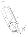
- Fig. 2 is a schematic perspective view of the feed roller 32 and its associated drive mechanism.
- a rotary unit 42 comprises the feed roller 32 and a worm wheel 44 mounted for joint rotation on a common axle 46.
- the rotary unit 42 is rotated in the direction of an arrow C, the substrate or, more exactly, the sub-portion 36b thereof, is advanced in a direction D relative to the printhead 18.
- a worm 48 is mounted to mesh with the worm wheel 44 and is driven by an electric motor 50.
- a disk-type encoder 52 is mounted on a drive shaft 54 of the motor 50 so as to detect angular increments by which the worm 48 is rotated.
- the encoder 24 may have 500 slots, so that, utilising quadrature encoding, it is possible to detect the angular increments with a resolution of 2000 per revolution.
- the worm gear formed by the worm 48 and the worm wheel 44 provides a very small transmission ratio k ⁇ 1, so that a relatively large angular displacement of the worm 48 leads only to a relatively small advance interval for the substrate.
- the encoder 52 permits to fine-control the sheet advance with very high accuracy.
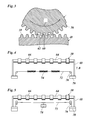
- the worm wheel 44 and the worm 48 have teeth 56 and 58, respectively, that are held in meshing engagement with one another with an inevitable amount of play.
- the position of the worm 48 does not exactly define the position of the worm wheel 44 and the feed roller 32, and, as a consequence, the position in which the substrate 16 stops on the print surface 20 (Fig. 1) is not exactly defined, neither, unless the play is eliminated.
- the additional function of the tension mechanism 38 is to eliminate this play. While the substrate sub-portion 36b is advanced in the direction of arrow D in Fig. 2, the tensioning mechanism 38 has a tendency to draw the substrate portion 36b back into the opposite direction. Since the substrate is in frictional contact with the feed roller 32, it exerts a torque on the rotary unit 42 in counterclock direction, as is symbolised by an arrow E in Fig. 3. As a result, the trailing tooth flanks 60 of the worm wheel 44 are reliably held in contact with the leading tooth flanks 62 of the worm 48, at least in a condition in which the rotary unit 42 stops.
- a pre-tensioning force is selected in the range from 1 to 100 N, or from 5 to 50 N, dependent on the media type and the mass of the feed roller 32. Under these conditions, the print position of the substrate 16 can be controlled with high accuracy.
- Fig. 4 illustrates a possible construction of the tensioning mechanism 38.
- the guide member 30 is formed by a shaft 64 carrying a number of rollers 66 supporting the substrate.
- the shaft 64 is rotatably supported between brackets 68 that are slidingly movable along guides (not shown).
- the ends 70 of the brackets 68 are interconnected by a tension rope 72 that contains a series of weak tension springs 74 and is passed over rollers 76 that are held stationary relative to the guide.
- the springs 74 create a biasing force acting upon the brackets 68 and the guide member 30 in the direction of arrow A.
- the amount of the biasing force will depend on the position of the guide member 30, i.e. it will be larger in the position shown in phantom lines in Fig. 1 and smaller in the position shown in continuous lines.
- the springs 74 are appropriately dimensioned, so that even in the position shown in continuous lines in Fig. 1, where the biasing force is smallest, the biasing force is still large enough to exert the required torque onto the worm wheel 44, as is shown in Fig. 3.
- Fig. 5 illustrates a modified embodiment in which the biasing force and hence the pre-tension of the substrate portion is position-independent.
- the direction of view is horizontal, so that the brackets 68 which extend along the axis A shown in Fig. 1, appear to be shortened.
- the tension of the tension rope 42 is created by the gravitational force of a weight member 78 suspended from the tension rope.
Landscapes
- Handling Of Sheets (AREA)
Abstract
A printer having an advance mechanism (12) for a print substrate (16), the advance mechanism comprising a feed roller (32) engaging the substrate (16) for applying a driving force thereto, a worm wheel (44) drivingly connected to the feed roller (32), a worm (48) meshing with the worm wheel, and a motor (50) for driving the worm (48), further comprising a tensioning mechanism (30,40) adapted to apply to a portion (36a,36b) of the substrate (16) adjacent to said feed roller (32) a pre-tension so adjusted that a torque applied to the feed roller (32) by said pre-tensioned substrate portion biases the worm wheel (44) relative to the worm (48), so that co-operating tooth flanks (60,62) of the worm wheel and the worm are held in contact with one another.
Description
- The invention relates to a printer having an advance mechanism for a print substrate, the advance mechanism comprising a feed roller engaging the substrate for applying a driving force thereto, a worm wheel drivingly connected to the feed roller, a worm meshing with the worm wheel, and a motor for driving the worm.
- In a scanning-type printer, a feed roller is frequently used for advancing a sheet of paper or any other print substrate in a specified direction past a printhead, so that the print substrate is scanned with the printhead. The speed or the length of the advance steps with which the sheet is moved relative to the printhead must accordingly be controlled with high accuracy, in order to obtain a good image quality. For example, in a typical set-up of an inkjet printer, a multi-nozzle printhead is mounted on a carriage which travels across the print substrate sheet in a main scanning direction normal to the direction of sheet advance, so that an image swath of several pixel lines is printed on the sheet in each pass of the printhead. Then, the sheet is advanced by the width of the swath, so that the next swath can be printed in a position precisely adjoining to the previous swath. In his case, the width of the sheet advance steps must be controlled with sufficient accuracy, so that the adjacent swaths are perfectly "stitched" together and will neither overlap nor form a gap. If the resolution of the printer is 600 dpi, for example, the width of a single pixel line is only 42µm, and the tolerances allowed for the length of the sheet advance step must even be significantly smaller than this.
- A worm-type drive mechanism has the advantage that it provides a high transmission ratio, so that the speed of revolution of the worm is much larger that that of the feed roller. As a consequence, the sheet advance increments provided by the feed roller amount only to a small fraction of the angular increments of the worm, so that a high control accuracy can be achieved by counting the worm increments.
- However, a worm-type drive mechanism, like other drive mechanisms employing toothed gears meshing with one another, has the drawback that an inevitable play between the teeth of the worm wheel and the worm may lead to positional inaccuracies. This is particularly the case for an advance mechanism of the type described above, wherein the feed roller is driven intermittently or, more generally, with a non-constant driving force. As long as the feed roller is accelerated, the leading tooth flanks of the worm will be in contact with the trailing tooth flanks of the worm wheel, so that a driving torque is transmitted onto the worm wheel, and the gear play will not have a detrimental effect. However, when the feed roller is decelerated, the moment of inertia may cause the feed roller to advance relative to the worm, so that the meshing teeth may be shifted relative to one another within their range of play. As a result, the position in which the feed roller and the print substrate come to rest may not be defined with sufficient accuracy.
- It should be observed here that gear play is not the only source of positional errors in a worm-type drive mechanism. Other errors may for example result from eccentricities of the worm wheel and/or the worm or from inaccuracies in the shape in which the teeth of the worm wheel and the worm have been machined. In contrast to the errors resulting from gear play, such machining arrows may however be compensated for by suitable calibration techniques.
- Mechanisms for eliminating gear play are generally known in the art of high precision gear transmission systems. However, such known mechanisms are relatively complex and expensive and may have other drawbacks such as an increase in frictional resistance and wear, an increased sensitiveness to machining inaccuracies and the like.
- It is therefore an object of the invention to provide a printer of the type indicated above, in which effects of a play between the teeth of the worm wheel and the worm can be eliminated in a simple and reliable way.
- According to the invention, this object is achieved by a tensioning mechanism adapted to apply to a portion of the substrate adjacent to said feed roller a pre-tension so adjusted that a torque applied to the feed roller by said pre-tensioned substrate portion biases the worm wheel relative to the worm, so that co-operating tooth flanks of the worm wheel and the worm are held in contact with one another.
- Thus, a pre-tension of the substrate is utilised for eliminating the play between the worm wheel and the worm, so that the print substrate can be positioned with high accuracy.
- The amount of pre-tension applied to the print substrate may be comparatively small. For example, when the substrate is advanced intermittently, it may be sufficient that the torque generated by the pre-tensioned substrate biases the worm wheel to such an extent that the co-operating tooth flanks are reliably held in contact with one another as soon the feed roller and the substrate have come to rest after an advance step, so that the substrate will be in the correct position when the print operation for the next swath of the image starts.
- Useful details and further developments of the invention are indicated in the dependent claims.
- When the print substrate is to be advanced unidirectionally, i.e. only in a single direction, either intermittently or continuously, the pre-tension may be applied either to the substrate portion downstream of the feed roller or to the portion upstream of the feed roller. When the tensioning mechanism is provided downstream of the feed roller, it will have the tendency to draw the substrate over the feed roller and to drive the same in advance direction, whereas the worm-type drive mechanism will have the function to retard this movement in a controlled way. Then, the pre-tension will assure that the leading tooth flanks of the worm wheel (in direction of rotation of the worm wheel) will always be held in engagement with the trailing tooth flanks of the worm. In a preferred embodiment, however, the tensioning mechanism is provided on the upstream side of the feed roller, so that the driving force of the feed roller has to overcome the pre-tension of the substrate.
- In a specific type of printer, especially a printer in which the print substrate has the form of an endless web that is drawn off from a roll, a tensioning mechanism on the upstream side of the feed roller may be provided, anyway, for other reasons, e.g. in order to provide for a certain buffer action on the web portion passing from the supply roller to the feed roller. Then, in order to practice the invention, it will be sufficient to suitably adjust the pre-tensioning force generated by the tensioning mechanism, in order to make sure that this force will be in a suitable range under all operating conditions that may occur during normal operation of the printer.
- In a preferred embodiment, the tensioning mechanism comprises a guide member which deflects the portion of the print substrate between a supply mechanism and the feed roller and is biased in a direction tending to increase the length of this substrate portion. The advance mechanism may comprise a feed unit located upstream of the feed roller and adapted to supply the substrate with a speed that, on the average, corresponds to the average speed of the feed roller but may momentarily deviate from the speed of the feed roller.
- Preferred embodiments of the invention will now be described in conjunction with the drawings, wherein:
- Fig. 1
- is a diagram of a printer according to a specific embodiment of the present invention;
- Fig. 2
- is a schematic perspective view of a feed roller and an associated worm-type drive mechanism;
- Fig. 3
- is an enlarged sectional view of parts of a worm wheel and a worm of the drive mechanism;
- Fig. 4
- is a schematic plan view of essential parts of a tensioning mechanism; and
- Fig. 5
- is a schematic perspective view of a tensioning mechanism according to a modified embodiment.
- The printer shown in Fig. 1 comprises a
supply unit 10, atransport unit 12 and aprint engine 14. Thesupply unit 10 serves for the storage and delivery of asubstrate 16 for printing. Thetransport unit 12 transports thesubstrate 16 from thesupply unit 10 to theprint engine 14 and also provides for accurate positioning of the substrate in a print zone in the print engine. In this embodiment, theprint engine 14 is a conventional ink jet engine which comprises aprinthead 18 arranged above aprint surface 20 and adapted to move back and forth across thesubstrate 16 on theprint surface 20 in a direction normal to the plane of the drawing in Fig. 1. Theprinthead 18 has only a limited printing range, so that it is necessary to print the image on the substrate in different sub-images. To this end, thesubstrate 16 is advanced intermittently, and a sub-image or swath is printed in each interval between two subsequent advance steps. The increments by which thesubstrate 16 is advanced over theprint surface 20 are precisely controlled, so that the sub-images will exactly adjoin to one another. - In the example shown, the
substrate 16 comes from aroll 22 that is rotatably supported in thesupply unit 10. Thesubstrate 16 has the form of a web having a length 150 m, for example, that is wound on theroll 22. In the example shown, the printer is a large format printer, and the width of the web corresponds to the smaller side of a document in A0 format. A pair ofdrive rollers 24 serves for drawing thesubstrate 16 off from theroll 22. The web drawn off from the roll is passed over adeflection roller 26 and is then paid out towards thetransport unit 12. - In the
transport unit 12, the web-type print substrate passes through a nip between a pair ofrollers 28 forming a first feed unit, is deflected at aguide member 30 and is then passed on towards a nip of a second feed unit comprising a drivenfeed roller 32 and apressure roller 34. The drivenfeed roller 32 controls the length of the increments with which thesubstrate 16 is advanced over theprint surface 20. - A portion of the
substrate 16 adjoining thefeed roller 32 on the upstream side is divided by theguide member 30 into twosub-portions guide member 30, which may be a roller or a stationary member, is movable along an axis A bisecting the angle between thesub-portions substrate portion movable guide member 30 and its guide and biasing mechanism serve as a tensioning mechanism 38. In Fig. 1 the elastic bias of theguide member 30 has been symbolised by acompression spring 40. - In view of the fact that, on the one hand, the
substrate 16 is advanced intermittently by thefeed roller 32 and, on the other hand, theroll 22 in thesupply unit 10 may have a considerable moment of inertia, so that large forces are required for accelerating and decelerating the same, one of the functions of the tensioning mechanism 38 in thetransport unit 12 is to provide a buffer in the feed path of the web and to protect the web against successive strains. This buffer action may for example be accomplished as follows. When thefeed roller 32 stops, theguide member 30 will be in the extended position shown in phantom lines in Fig. 1, so that the length of thesubstrate portion feed roller 32 starts to rotate with a comparatively large acceleration, whereas the roller pairs 24 and 28 accelerate the web with a smaller acceleration. As a result, a part of the length of thesubstrate portion guide member 30 is moved against the biasing force of thespring 40 towards the position shown in continuous lines in Fig. 1. Conversely, at the end of the advance step, thefeed roller 32 will be stopped relatively abruptly, whereas the roller pairs 24 and 28 will decelerate the web with a moderate deceleration. Consequently, theguide member 30 will move back towards the position shown in phantom lines, so as to eliminate a possible slack in thesubstrate portion - According to the invention, the tensioning mechanism 38 has an additional function which will now be explained in conjunction with Figs. 2 and 3. Fig. 2 is a schematic perspective view of the
feed roller 32 and its associated drive mechanism. - A
rotary unit 42 comprises thefeed roller 32 and aworm wheel 44 mounted for joint rotation on acommon axle 46. When therotary unit 42 is rotated in the direction of an arrow C, the substrate or, more exactly, the sub-portion 36b thereof, is advanced in a direction D relative to theprinthead 18. - A
worm 48 is mounted to mesh with theworm wheel 44 and is driven by anelectric motor 50. A disk-type encoder 52 is mounted on adrive shaft 54 of themotor 50 so as to detect angular increments by which theworm 48 is rotated. By way of example, theencoder 24 may have 500 slots, so that, utilising quadrature encoding, it is possible to detect the angular increments with a resolution of 2000 per revolution. - The worm gear formed by the
worm 48 and theworm wheel 44 provides a very small transmission ratio k << 1, so that a relatively large angular displacement of theworm 48 leads only to a relatively small advance interval for the substrate. Thus, in principle, theencoder 52 permits to fine-control the sheet advance with very high accuracy. - However, as is shown in Fig. 3, the
worm wheel 44 and theworm 48 haveteeth worm 48 does not exactly define the position of theworm wheel 44 and thefeed roller 32, and, as a consequence, the position in which thesubstrate 16 stops on the print surface 20 (Fig. 1) is not exactly defined, neither, unless the play is eliminated. - The additional function of the tension mechanism 38 is to eliminate this play. While the
substrate sub-portion 36b is advanced in the direction of arrow D in Fig. 2, the tensioning mechanism 38 has a tendency to draw thesubstrate portion 36b back into the opposite direction. Since the substrate is in frictional contact with thefeed roller 32, it exerts a torque on therotary unit 42 in counterclock direction, as is symbolised by an arrow E in Fig. 3. As a result, the trailing tooth flanks 60 of theworm wheel 44 are reliably held in contact with the leading tooth flanks 62 of theworm 48, at least in a condition in which therotary unit 42 stops. Thus, the pre-tension applied to thesubstrate portion rotary unit 42 and the moment of inertia of the rotary unit, so that the contacting condition of the tooth flanks 60 and 62 shown in Fig. 3 will be maintained or at least immediately restored after the rotary unit has stopped and before the next print cycle commences. In a practical embodiment, a pre-tensioning force is selected in the range from 1 to 100 N, or from 5 to 50 N, dependent on the media type and the mass of thefeed roller 32. Under these conditions, the print position of thesubstrate 16 can be controlled with high accuracy. - Fig. 4 illustrates a possible construction of the tensioning mechanism 38. The
guide member 30 is formed by ashaft 64 carrying a number ofrollers 66 supporting the substrate. Theshaft 64 is rotatably supported betweenbrackets 68 that are slidingly movable along guides (not shown). The ends 70 of thebrackets 68 are interconnected by atension rope 72 that contains a series of weak tension springs 74 and is passed overrollers 76 that are held stationary relative to the guide. Thus, thesprings 74 create a biasing force acting upon thebrackets 68 and theguide member 30 in the direction of arrow A. - In this embodiment, the amount of the biasing force will depend on the position of the
guide member 30, i.e. it will be larger in the position shown in phantom lines in Fig. 1 and smaller in the position shown in continuous lines. Thesprings 74 are appropriately dimensioned, so that even in the position shown in continuous lines in Fig. 1, where the biasing force is smallest, the biasing force is still large enough to exert the required torque onto theworm wheel 44, as is shown in Fig. 3. - Fig. 5 illustrates a modified embodiment in which the biasing force and hence the pre-tension of the substrate portion is position-independent. Here, the direction of view is horizontal, so that the
brackets 68 which extend along the axis A shown in Fig. 1, appear to be shortened. The tension of thetension rope 42 is created by the gravitational force of aweight member 78 suspended from the tension rope.
Claims (6)
- A printer having an advance mechanism (12) for a print substrate (16), the advance mechanism comprising a feed roller (32) engaging the substrate (16) for applying a driving force thereto, a worm wheel (44) drivingly connected to the feed roller (32), a worm (48) meshing with the worm wheel, and a motor (50) for driving the worm (48), characterised by a tensioning mechanism (38) adapted to apply to a portion (36a, 36b) of the substrate (16) adjacent to said feed roller (32) a pre-tension so adjusted that a torque applied to the feed roller (32) by said pre-tensioned substrate portion biases the worm wheel (44) relative to the worm (48), so that co-operating tooth flanks (60, 62) of the worm wheel and the worm are held in contact with one another.
- The printer according to claim 1, wherein the feed roller (32) is adapted to advance the substrate (16) intermittently over a print surface (20) and past a printhead (18).
- The printer according to claim 1 or 2, wherein the tensioning mechanism (38) is arranged on an upstream side of the feed roller (32).
- The printer according to claim 3, comprising a supply unit (10) in which the print substrate (16) is drawn off from a roll (22) and supplied to the advance mechanism (12) in the form of an endless web.
- The printer according to claim 3 or 4, wherein said tensioning mechanism (38) is arranged at a substrate portion (36a, 36b) formed between a first feed unit (28) and said feed roller (32), said first feed unit (28) and said feed roller (32) are adapted to be driven independently from one another, and the tension mechanism (38) is arranged to eliminate a slack in the substrate portion (38a, 38b).
- The printer according to any of the preceding claims, wherein the pre-tensioning force applied to the substrate portion (36a, 36b) by the tensioning mechanism (38) is in the range from 5 to 50 N.
Priority Applications (1)
| Application Number | Priority Date | Filing Date | Title |
|---|---|---|---|
| EP05110072A EP1780029A1 (en) | 2005-10-27 | 2005-10-27 | Printer with advance mechanism for a print substrate |
Applications Claiming Priority (1)
| Application Number | Priority Date | Filing Date | Title |
|---|---|---|---|
| EP05110072A EP1780029A1 (en) | 2005-10-27 | 2005-10-27 | Printer with advance mechanism for a print substrate |
Publications (1)
| Publication Number | Publication Date |
|---|---|
| EP1780029A1 true EP1780029A1 (en) | 2007-05-02 |
Family
ID=36441318
Family Applications (1)
| Application Number | Title | Priority Date | Filing Date |
|---|---|---|---|
| EP05110072A Withdrawn EP1780029A1 (en) | 2005-10-27 | 2005-10-27 | Printer with advance mechanism for a print substrate |
Country Status (1)
| Country | Link |
|---|---|
| EP (1) | EP1780029A1 (en) |
Cited By (10)
| Publication number | Priority date | Publication date | Assignee | Title |
|---|---|---|---|---|
| EP2110258A1 (en) * | 2008-04-10 | 2009-10-21 | Seiko Epson Corporation | Method of controlling paper transportation in a printer, and a printer using the method |
| CN102211471A (en) * | 2010-03-29 | 2011-10-12 | 精工爱普生株式会社 | Roll paper printer |
| CN102218944A (en) * | 2010-03-29 | 2011-10-19 | 精工爱普生株式会社 | Roll paper printer and method of opening and closing a roll paper printer cover |
| EP2826632A3 (en) * | 2013-07-18 | 2015-02-25 | Roland DG Corporation | Tension fluctuation alleviating device for use in fabric printing apparatus and printing apparatus |
| EP2985250A1 (en) * | 2014-08-10 | 2016-02-17 | Kornit Digital Technologies Ltd. | Tensioning mechanism for a textile feed to a stepped operation digital textile printer |
| US20170275119A1 (en) * | 2016-03-28 | 2017-09-28 | Seiko Epson Corporation | Medium feeding apparatus |
| JP2018039149A (en) * | 2016-09-06 | 2018-03-15 | 東芝テック株式会社 | Print unit and printer |
| EP3590877A1 (en) * | 2018-07-02 | 2020-01-08 | OCE Holding B.V. | Dancer suspension assembly for a roll-to-roll printer |
| EP3708527A1 (en) * | 2019-03-06 | 2020-09-16 | Ricoh Company, Ltd. | Adjustable web handling mechanism |
| US20250128902A1 (en) * | 2023-10-19 | 2025-04-24 | Kinpo Electronics, Inc. | Printing equipment and continuous feeding and cutting device thereof |
Citations (4)
| Publication number | Priority date | Publication date | Assignee | Title |
|---|---|---|---|---|
| EP0795412A1 (en) * | 1996-03-12 | 1997-09-17 | Seiko Epson Corporation | Single motor and drive shaft with several worms for a printer |
| US5825374A (en) * | 1997-03-12 | 1998-10-20 | Raster Graphics, Inc. | Apparatus and method for advancing a web |
| US6439786B1 (en) * | 1999-09-20 | 2002-08-27 | Scanvec Garment Systems, Ltd. | Synchronized motion printer with continuous paper movement |
| US6575555B1 (en) * | 1999-02-15 | 2003-06-10 | Nur Macroprinters Ltd. | Printing apparatus and substrate feeding system particularly useful therein |
-
2005
- 2005-10-27 EP EP05110072A patent/EP1780029A1/en not_active Withdrawn
Patent Citations (4)
| Publication number | Priority date | Publication date | Assignee | Title |
|---|---|---|---|---|
| EP0795412A1 (en) * | 1996-03-12 | 1997-09-17 | Seiko Epson Corporation | Single motor and drive shaft with several worms for a printer |
| US5825374A (en) * | 1997-03-12 | 1998-10-20 | Raster Graphics, Inc. | Apparatus and method for advancing a web |
| US6575555B1 (en) * | 1999-02-15 | 2003-06-10 | Nur Macroprinters Ltd. | Printing apparatus and substrate feeding system particularly useful therein |
| US6439786B1 (en) * | 1999-09-20 | 2002-08-27 | Scanvec Garment Systems, Ltd. | Synchronized motion printer with continuous paper movement |
Cited By (20)
| Publication number | Priority date | Publication date | Assignee | Title |
|---|---|---|---|---|
| EP2110258A1 (en) * | 2008-04-10 | 2009-10-21 | Seiko Epson Corporation | Method of controlling paper transportation in a printer, and a printer using the method |
| CN101554806B (en) * | 2008-04-10 | 2012-11-28 | 精工爱普生株式会社 | Paper feeding control method of printer and printer thereof |
| US8485462B2 (en) | 2008-04-10 | 2013-07-16 | Seiko Epson Corporation | Method of controlling paper transportation in an apparatus, and an apparatus using the method |
| CN102211471A (en) * | 2010-03-29 | 2011-10-12 | 精工爱普生株式会社 | Roll paper printer |
| CN102218944A (en) * | 2010-03-29 | 2011-10-19 | 精工爱普生株式会社 | Roll paper printer and method of opening and closing a roll paper printer cover |
| US8702330B2 (en) | 2010-03-29 | 2014-04-22 | Seiko Epson Corporation | Roll paper printer and method of opening and closing a roll paper printer cover |
| CN102218944B (en) * | 2010-03-29 | 2014-10-08 | 精工爱普生株式会社 | Roll paper printer and method of opening and closing a roll paper printer cover |
| CN102211471B (en) * | 2010-03-29 | 2015-01-28 | 精工爱普生株式会社 | Roll paper printer |
| EP2826632A3 (en) * | 2013-07-18 | 2015-02-25 | Roland DG Corporation | Tension fluctuation alleviating device for use in fabric printing apparatus and printing apparatus |
| US9227441B2 (en) | 2013-07-18 | 2016-01-05 | Roland Dg Corporation | Tension fluctuation alleviating device for use in fabric printing apparatus |
| EP2985250A1 (en) * | 2014-08-10 | 2016-02-17 | Kornit Digital Technologies Ltd. | Tensioning mechanism for a textile feed to a stepped operation digital textile printer |
| US9790047B2 (en) | 2014-08-10 | 2017-10-17 | Kornit Digital Technologies Ltd. | Tensioning mechanism for a textile feed to a stepped operation digital textile printer |
| US10407267B2 (en) | 2014-08-10 | 2019-09-10 | Kornit Digital Technologies Ltd. | Tensioning mechanism for a textile feed to a stepped operation digital textile printer |
| US20170275119A1 (en) * | 2016-03-28 | 2017-09-28 | Seiko Epson Corporation | Medium feeding apparatus |
| US10597248B2 (en) * | 2016-03-28 | 2020-03-24 | Seiko Epson Corporation | Medium feeding apparatus |
| JP2018039149A (en) * | 2016-09-06 | 2018-03-15 | 東芝テック株式会社 | Print unit and printer |
| EP3590877A1 (en) * | 2018-07-02 | 2020-01-08 | OCE Holding B.V. | Dancer suspension assembly for a roll-to-roll printer |
| EP3708527A1 (en) * | 2019-03-06 | 2020-09-16 | Ricoh Company, Ltd. | Adjustable web handling mechanism |
| US11535045B2 (en) | 2019-03-06 | 2022-12-27 | Ricoh Company, Ltd. | Adjustable web handling mechanism |
| US20250128902A1 (en) * | 2023-10-19 | 2025-04-24 | Kinpo Electronics, Inc. | Printing equipment and continuous feeding and cutting device thereof |
Similar Documents
| Publication | Publication Date | Title |
|---|---|---|
| US5488396A (en) | Printer print head positioning apparatus and method | |
| JP4886426B2 (en) | Recording apparatus and conveyance control method | |
| JPH06345284A (en) | Belt conveyor and intermediate transfer type ink jet recording apparatus using the same | |
| EP1129969B1 (en) | Sheet material conveying apparatus and recording apparatus | |
| JP3131103B2 (en) | Sheet transport device | |
| US6439786B1 (en) | Synchronized motion printer with continuous paper movement | |
| JP2002361958A (en) | Recording device and recording method | |
| US5050858A (en) | Sheet feed control method | |
| JP3767061B2 (en) | Printing device | |
| US7189018B2 (en) | Print media drive | |
| JP7480596B2 (en) | Image Recording Device | |
| JP2005343057A (en) | Recording device | |
| US7784892B2 (en) | Printer and method of controlling the same | |
| US6017160A (en) | Printer sheet feed device having controller | |
| JP2707228B2 (en) | Paper feed roll drive for printer | |
| US20060071390A1 (en) | Speed mode for printer media transport | |
| JP3703619B2 (en) | Printer paper feed mechanism | |
| US6851879B2 (en) | Image-recording device | |
| US20260027844A1 (en) | Advancing media trailing edges | |
| EP1780030B1 (en) | Printer with worm-driven feed roller | |
| JPH0592638A (en) | Regulating device for print head gap of printer | |
| JP2024047388A (en) | Conveying device and recording device | |
| JPH04226376A (en) | Method and device for adjusting start end position of continuous paper at tractor feed operation in printer | |
| JPS6131275A (en) | Automatic adjusting mechanism for printing head in wire dot printer | |
| US20130043646A1 (en) | Conveying apparatus and image forming apparatus |
Legal Events
| Date | Code | Title | Description |
|---|---|---|---|
| PUAI | Public reference made under article 153(3) epc to a published international application that has entered the european phase |
Free format text: ORIGINAL CODE: 0009012 |
|
| AK | Designated contracting states |
Kind code of ref document: A1 Designated state(s): AT BE BG CH CY CZ DE DK EE ES FI FR GB GR HU IE IS IT LI LT LU LV MC NL PL PT RO SE SI SK TR |
|
| AX | Request for extension of the european patent |
Extension state: AL BA HR MK YU |
|
| STAA | Information on the status of an ep patent application or granted ep patent |
Free format text: STATUS: THE APPLICATION HAS BEEN WITHDRAWN |
|
| RIN1 | Information on inventor provided before grant (corrected) |
Inventor name: GOEREE, BARRY B. Inventor name: COENEN, JEROEN J.G. |
|
| 18W | Application withdrawn |
Effective date: 20070515 |