EP1779978A1 - Staple cartridge - Google Patents
Staple cartridge Download PDFInfo
- Publication number
- EP1779978A1 EP1779978A1 EP05758350A EP05758350A EP1779978A1 EP 1779978 A1 EP1779978 A1 EP 1779978A1 EP 05758350 A EP05758350 A EP 05758350A EP 05758350 A EP05758350 A EP 05758350A EP 1779978 A1 EP1779978 A1 EP 1779978A1
- Authority
- EP
- European Patent Office
- Prior art keywords
- actuator
- staple
- refill
- main body
- staples
- Prior art date
- Legal status (The legal status is an assumption and is not a legal conclusion. Google has not performed a legal analysis and makes no representation as to the accuracy of the status listed.)
- Granted
Links
Images




Classifications
-
- B—PERFORMING OPERATIONS; TRANSPORTING
- B27—WORKING OR PRESERVING WOOD OR SIMILAR MATERIAL; NAILING OR STAPLING MACHINES IN GENERAL
- B27F—DOVETAILED WORK; TENONS; SLOTTING MACHINES FOR WOOD OR SIMILAR MATERIAL; NAILING OR STAPLING MACHINES
- B27F7/00—Nailing or stapling; Nailed or stapled work
- B27F7/17—Stapling machines
- B27F7/38—Staple feeding devices
Definitions
- the present invention relates to a staple cartridge being attached and detached to and from a containing portion of a stapler main body, including a mounting portion for attaching and detaching a refill contained with staples, and including actuators for detecting a presence/absence of the staples respectively to the refill mounting portion and a staple strike out portion.
- a staple at inside of a staple cartridge is supplied to a strike out portion and is struck out by a strike out mechanism.
- Inside of the staple cartridge is contained with connected staples connecting straight staples in a sheet-like shape or a strip-like shape.
- the sheet-like staples are contained by being laminated in multistages and the strip-like staples are contained by being wound in a roll-like shape.
- the former detecting mechanism is constituted by a structure of arranging a sensor for detecting a presence/absence of a staple at a staple guide portion formed between a staple discharge port of the staple cartridge and a strike out portion at a front end of the staple cartridge. According to the latter detecting mechanism, a hole is opened at the staple cartridge itself, and a sensor is operated by vacating the hole by passing a final staple through the hole.
- a control portion determines that the staple cartridge is mounted to the mounting portion and finishes to prepare a binding operation.
- the mechanism of striking out the staple is operated.
- the reused type staple cartridge is constituted such that a refill contained with staples at inside of the case is made to be attachable and detachable to and from a cartridge main body, when all of the staples in the refill have been consumed, only the refill is removed and a separate refill is mounted.
- One or more embodiments of the invention provide a staple cartridge particularly effective in detecting that a refill is halfly set.
- a staple cartridge is characterized by a cartridge main body attached and detached to and from a stapler main body, and a refill contained with connected staples at an inside thereof, the refill is interchangeably attached to the cartridge main body, one end side of the staple cartridge is provided with a mounting portion of the refill, a guide portion for guiding the connected staples in the refill to a strike out portion is provided between the refill mounting portion and the staple strike out portion at other end, a second actuator operated in accordance with a presence/absence of the connected staples at an inside of the refill mounting portion and a first actuator operated in accordance with a presence/absence of the connected staples at an inside of the guide portion are respectively arranged at the lower portions of the refill mounting portion and the guide portion, and the first actuator and the second actuator are interlocked.
- the second actuator is pivoted around a middle portion in accordance with the presence/absence of the connected staples at the inside of the refill mounting portion
- the first actuator is pivoted around a middle portion in accordance with the presence/absence of the connected staples at the inside of the guide portion
- the first actuator and the second actuator are aligned in series
- end portions of the first actuator and the second actuator contiguous to each other are connected to be engaged such that by pivoting one thereof, the other thereof is moved interlockingly.
- a staple cartridge is provided with a cartridge main body, a staple strike out portion, a connected staple containing portion provided on one end side, a staple strike out portion provided on the other end side, a guide portion for guiding connected staples at the inside of the connected staple containing portion to the staple strike out portion, a first actuator capable of entering and exiting to and from the guide portion, and a second actuator capable of entering and exiting to and from an inside of the connected staple containing portion.
- the first actuator and the second actuator are interlocked.
- the connected staple containing portion is contained with the refill containing the connected staples at an inside thereof and interchangeably attached to the cartridge main body, and the second actuator is made to be able to enter and exit to and from the inside of the refill.
- the cartridge main body is attached and detached to and from the stapler main body, the first actuator is operated in accordance with a presence/absence of the connected staples at an inside of the guide portion, and the second actuator is operated in accordance with a presence/absence of the connected staples at an inside of the connected staple containing portion.
- the second actuator is pivoted around a second middle portion
- the first actuator is pivoted around a first middle portion
- the first actuator and the second actuator are aligned in series
- end portions of the first actuator and the second actuator contiguous to each other are connected to be engaged such that by pivoting one thereof, the other is interlocked.
- one or more embodiments of the invention provide connected staples contained in the staple cartridge.
- one or more embodiments of the invention provide a refill contained in the staple cartridge.
- one or more embodiments of the invention provide connected staples contained in the refill.
- Fig. 1 shows a staple cartridge.
- the staple cartridge A is constituted by a cartridge main body 1 and a refill 2.
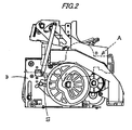
- the cartridge main body 1 is attached and detached to and from a stapler main body 3 as shown in Fig.2, a rear end portion thereof is provided with an attachment/detachment operating knob 4, a rear end side thereof is provided with the portion 5 of mounting the refill 2 (connected staples containing portion), and the guide portion 7 for guiding connected staples at inside of the refill 2 to the strike out portion 6 is provided between the refill mounting portion 5 and the staple strike out portion 6 at the other end thereof.
- the refill 2 is contained with staples (a) in a roll-like shape at inside of a refill case 2a, the refill case 2a is formed with a knob 8 on an upper side of a case main body in a cylindrical shape, and formed with a discharge port 9 (refer to Fig.3) of the staple at one end on a lower side, and the discharge port 9 is for discharging the roll staple and is formed in a shape of a flat square cylinder.
- a bottom portion of a base 1a of the cartridge main body 1 is formed with a slender opening portion 10 at one side in a width direction thereof. Further, the opening portion 10 is arranged with the first actuator 11 and the second actuator 12 to be arranged in series respectively at lower portions of the guide portion 7 and the refill mounting portion 5.
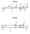
- the first actuator 11 is provided pivotably in an up and down direction around a support shaft of a middle portion (first middle portion) 13, formed with a projected portion 14 projected to a lower side at a front end (end portion on a side of the strike out portion 6) thereof, formed with a projected portion 15 in a triangular shape projected to an upper side of a portion thereof in correspondence with the guide portion 7, and formed with a shaft portion 16 at a side of a rear end portion thereof.
- the second actuator 12 is provided pivotably in the up and down direction around a support shaft of a middle portion (second middle portion) 17 and formed with an engaging groove 18 at a front end portion thereof. Further, a rear end portion thereof is formed with a bent portion 19 projected to an upper side.
- the first actuator 11 is arranged so that the projected portion 15 enters and exits to and from the guide portion 7 by being pivoted.
- a front end of the bent portion 19 is able to enter and exit to and from an inner side of the case of the refill 2 from a hole 20 (refer to Fig.3) formed at a bottom portion of the refill case 2a of the refill 2 mounted correctly to the mounting portion 5. Therefore, the second actuator 12 is operated in accordance with a presence/absence of the connected staples (a) at an inside of the refill mounting portion 5, and the first actuator 11 is constituted to operate in accordance with a presence/absence of the connected staples at an inside of the guide portion 7.
- the rear end portion of the first actuator 11 and the front end portion of the second actuator 12 are connected to engage such that the first actuator 11 and the second actuator 12 are interlocked in the same up and down direction simultaneously with each other by engaging the shaft portion 16 to the engaging groove 18. That is, when one of a free end thereof is moved upward, also a free end of the other thereof is moved upward, and when the free end of the one is moved downward, also the free end of the other is moved downward.
- the front end projected portion 14 of the first actuator 11 is attached to correspond to a sensor S (for example, relief switch, limit switch) provided at the stapler main body 3 of Fig.2.
- a sensor S for example, relief switch, limit switch
- the second actuator 12 is not operated and therefore, also the sensor S provided on the side of the stapler main body cannot detect the refill 2 and cannot detect presence of the connected staples. Therefore, the binding operation cannot be carried out and therefore, an operator notices the half set state and can correctly reset the refill 2.
- first actuator 11 and the second actuator 12 are aligned in series, end portions of the first actuator 11 and the second actuator 12 contiguous each other are connected to be engaged such that by pivoting one thereof, the other is interlocked and therefore, the sensor S in correspondence with the first actuator 11 or the second actuator 12 may be provided on the side of the stapler main body. Therefore, a number of parts is small and also a structure can be simplified.
- the staple cartridge A is mounted to the cartridge mounting portion opened at the rear portion of the stapler main body.
- the side of the cartridge main body 1 is provided with a feeding mechanism for feeding out the staple in the staple cartridge to the side of the strike out portion, a forming/striking out mechanism for forming the staple fed to the strike out portion in a C-shape and thereafter striking out the staple, a clincher mechanism of folding to bend a leg portion of the staple struck out by the striking mechanism to penetrate to a sheet on a binding base and so on, since the mechanisms are publicly known, an explanation thereof will be omitted.
- a second actuator in setting a refill to a cartridge main body, when the refill is not correctly set to a predetermined position, a second actuator is not operated and therefore, also a sensor provided on a side of the cartridge main body cannot detect the refill and cannot detect presence of a connected staple. Therefore, binding operation cannot be carried out and therefore, an operator notices a half set state and can correctly reset the refill.
- the sensor on the side of the cartridge main body may be provided to correspond to either one of the actuators and therefore, there is achieved an advantage of reducing the number of parts and simplifying the structure.
- the first actuator and the second actuator are arranged to align in series, the contiguous end portions of the first actuator and the second actuator are connected to engage such that by pivoting one thereof, the other thereof is interlocked and therefore, the sensor in correspondence with the first actuator or the second actuator may be provided on the side of the stapler main body. Therefore, the number of parts can be reduced and also the structure can be simplified.
Landscapes
- Engineering & Computer Science (AREA)
- Mechanical Engineering (AREA)
- Life Sciences & Earth Sciences (AREA)
- Forests & Forestry (AREA)
- Portable Nailing Machines And Staplers (AREA)
- Dovetailed Work, And Nailing Machines And Stapling Machines For Wood (AREA)
Abstract
Description
- The present invention relates to a staple cartridge being attached and detached to and from a containing portion of a stapler main body, including a mounting portion for attaching and detaching a refill contained with staples, and including actuators for detecting a presence/absence of the staples respectively to the refill mounting portion and a staple strike out portion.
- In an electric stapler, a staple at inside of a staple cartridge is supplied to a strike out portion and is struck out by a strike out mechanism. Inside of the staple cartridge is contained with connected staples connecting straight staples in a sheet-like shape or a strip-like shape. The sheet-like staples are contained by being laminated in multistages and the strip-like staples are contained by being wound in a roll-like shape.
- There is a mechanism of detecting whether connected staples remain in a staple cartridge at a stapler main body as a mechanism for detecting staples (
JP-A-2003-062765 JP-A-2002-079475 - When it is detected that the front end of the staple cartridge reaches a portion of mounting a cartridge main body, a control portion determines that the staple cartridge is mounted to the mounting portion and finishes to prepare a binding operation. When the instruction of the binding operation is issued under the state, the mechanism of striking out the staple is operated.
- Meanwhile, there are a staple cartridge which is disposed after consuming up staples at inside thereof and a staple cartridge which is reused. The reused type staple cartridge is constituted such that a refill contained with staples at inside of the case is made to be attachable and detachable to and from a cartridge main body, when all of the staples in the refill have been consumed, only the refill is removed and a separate refill is mounted.
- However, although a problem is not posed when the refill is normally mounted to the mounting portion of the cartridge main body in the reused type, when the refill is halfly set (incompletely mounted), the refill is not engaged with a feed claw of a mechanism of feeding out staples in the refill from a guide portion to a strike out portion and therefore, the staples are not fed even when a feed mechanism is operated. Therefore, binding is not carried out after striking out staples remaining in the guide portion.
- One or more embodiments of the invention provide a staple cartridge particularly effective in detecting that a refill is halfly set.
- A staple cartridge according to one or more embodiments of the invention is characterized by a cartridge main body attached and detached to and from a stapler main body, and a refill contained with connected staples at an inside thereof, the refill is interchangeably attached to the cartridge main body, one end side of the staple cartridge is provided with a mounting portion of the refill, a guide portion for guiding the connected staples in the refill to a strike out portion is provided between the refill mounting portion and the staple strike out portion at other end, a second actuator operated in accordance with a presence/absence of the connected staples at an inside of the refill mounting portion and a first actuator operated in accordance with a presence/absence of the connected staples at an inside of the guide portion are respectively arranged at the lower portions of the refill mounting portion and the guide portion, and the first actuator and the second actuator are interlocked.
- According to one or more embodiments of the invention, the second actuator is pivoted around a middle portion in accordance with the presence/absence of the connected staples at the inside of the refill mounting portion, the first actuator is pivoted around a middle portion in accordance with the presence/absence of the connected staples at the inside of the guide portion, the first actuator and the second actuator are aligned in series, and end portions of the first actuator and the second actuator contiguous to each other are connected to be engaged such that by pivoting one thereof, the other thereof is moved interlockingly.
- Further, according to one ormore embodiments of embodiments of the invention, a staple cartridge is provided with a cartridge main body, a staple strike out portion, a connected staple containing portion provided on one end side, a staple strike out portion provided on the other end side, a guide portion for guiding connected staples at the inside of the connected staple containing portion to the staple strike out portion, a first actuator capable of entering and exiting to and from the guide portion, and a second actuator capable of entering and exiting to and from an inside of the connected staple containing portion. The first actuator and the second actuator are interlocked.
- According to one or more embodiments of the invention, the connected staple containing portion is contained with the refill containing the connected staples at an inside thereof and interchangeably attached to the cartridge main body, and the second actuator is made to be able to enter and exit to and from the inside of the refill.
- According to one or more embodiments of the invention, the cartridge main body is attached and detached to and from the stapler main body, the first actuator is operated in accordance with a presence/absence of the connected staples at an inside of the guide portion, and the second actuator is operated in accordance with a presence/absence of the connected staples at an inside of the connected staple containing portion.
- According to one or more embodiments of the invention, the second actuator is pivoted around a second middle portion, the first actuator is pivoted around a first middle portion, the first actuator and the second actuator are aligned in series, and end portions of the first actuator and the second actuator contiguous to each other are connected to be engaged such that by pivoting one thereof, the other is interlocked.
- Further, one or more embodiments of the invention provide connected staples contained in the staple cartridge.
- Further, one or more embodiments of the invention provide a refill contained in the staple cartridge.
- Further, one or more embodiments of the invention provide connected staples contained in the refill.
- Other aspects and advantages of the invention will be apparent from the following description and the appended claims.
-
- [Fig.1]
Fig.1 is a perspective view of a staple cartridge according to one or more embodiments of the invention. - [Fig.2]
Fig.2 is a side view of a stapler mounted with a staple cartridge. - [Fig.3]
Fig.3 is a vertical sectional view of a staple cartridge. - [Fig.4]
Fig.4 is a perspective view of a base of a cartridge main body. - [Fig.5 (a)]
Fig.5 (a) is a side view showing a state of connecting a first and a second actuator. - [Fig.5 (b)]
Fig. 5 (b) is a bottom view showing the state of connecting the first and the second actuators. - [Fig.6]
Fig.6 is a vertical sectional view showing a staple cartridge in a state of normal time. - [Fig.7]
Fig.7 is a vertical sectional view of a staple cartridge showing a state in half set time. - [Fig.8]
Fig.8 is a vertical sectional view of a staple cartridge showing a state in which a remaining amount of staples is small. - [Fig.9]
Fig.9 is a vertical sectional view of a staple cartridge showing a state in which staples are consumed up. -
- a
- (connected) staples
- 1
- cartridge main body
- 2
- refill
- 5
- refill mounting portion
- 6
- strike out portion
- 7
- guide portion
- 11
- first actuator
- 12
- second actuator
- An explanation will be given of one or more embodiments of the invention in reference to the drawings as follows.
- Fig. 1 shows a staple cartridge. The staple cartridge A is constituted by a cartridge
main body 1 and arefill 2. - The cartridge
main body 1 is attached and detached to and from a staplermain body 3 as shown in Fig.2, a rear end portion thereof is provided with an attachment/detachment operating knob 4, a rear end side thereof is provided with theportion 5 of mounting the refill 2 (connected staples containing portion), and theguide portion 7 for guiding connected staples at inside of therefill 2 to the strike outportion 6 is provided between therefill mounting portion 5 and the staple strike outportion 6 at the other end thereof. - The
refill 2 is contained with staples (a) in a roll-like shape at inside of a refill case 2a, the refill case 2a is formed with aknob 8 on an upper side of a case main body in a cylindrical shape, and formed with a discharge port 9 (refer to Fig.3) of the staple at one end on a lower side, and the discharge port 9 is for discharging the roll staple and is formed in a shape of a flat square cylinder. - Next, as shown by Fig.3 and Fig.4, a bottom portion of a base 1a of the cartridge
main body 1 is formed with aslender opening portion 10 at one side in a width direction thereof. Further, the openingportion 10 is arranged with thefirst actuator 11 and thesecond actuator 12 to be arranged in series respectively at lower portions of theguide portion 7 and therefill mounting portion 5. - As shown by Fig.5 (a) and Fig.5 (b), the
first actuator 11 is provided pivotably in an up and down direction around a support shaft of a middle portion (first middle portion) 13, formed with a projectedportion 14 projected to a lower side at a front end (end portion on a side of the strike out portion 6) thereof, formed with a projectedportion 15 in a triangular shape projected to an upper side of a portion thereof in correspondence with theguide portion 7, and formed with ashaft portion 16 at a side of a rear end portion thereof. - Also the
second actuator 12 is provided pivotably in the up and down direction around a support shaft of a middle portion (second middle portion) 17 and formed with an engaginggroove 18 at a front end portion thereof. Further, a rear end portion thereof is formed with abent portion 19 projected to an upper side. - The
first actuator 11 is arranged so that the projectedportion 15 enters and exits to and from theguide portion 7 by being pivoted. By pivoting thesecond actuator 12, a front end of thebent portion 19 is able to enter and exit to and from an inner side of the case of therefill 2 from a hole 20 (refer to Fig.3) formed at a bottom portion of the refill case 2a of therefill 2 mounted correctly to the mountingportion 5. Therefore, thesecond actuator 12 is operated in accordance with a presence/absence of the connected staples (a) at an inside of therefill mounting portion 5, and thefirst actuator 11 is constituted to operate in accordance with a presence/absence of the connected staples at an inside of theguide portion 7. - Next, the rear end portion of the
first actuator 11 and the front end portion of thesecond actuator 12 are connected to engage such that thefirst actuator 11 and thesecond actuator 12 are interlocked in the same up and down direction simultaneously with each other by engaging theshaft portion 16 to the engaginggroove 18. That is, when one of a free end thereof is moved upward, also a free end of the other thereof is moved upward, and when the free end of the one is moved downward, also the free end of the other is moved downward. - When the staple cartridge A having the above-described constitution is mounted to a predetermined position of the stapler
main body 3, the front end projectedportion 14 of thefirst actuator 11 is attached to correspond to a sensor S (for example, relief switch, limit switch) provided at the staplermain body 3 of Fig.2. Thereby, when the front end projectedportion 14 of thefirst actuator 11 is moved downward, or when the rear endbent portion 19 of thesecond actuator 12 is moved downward, the sensor S is set to be ON (detect). - Hence, an explanation will be given of how the
first actuator 11 and thesecond actuator 12 are operated in accordance with the presence/absence of the staple at the inside of the staple guide and at the inside of therefill 2 when the staple cartridge A is mounted to the staplermain body 3 as follows. -
- (1) In interchanging the refill 2 (when there is not staples at insides of the
refill 2 and the guide portion 7), as shown by Fig.6, anew refill 2 is mounted to therefill mounting portion 5, the rear endbent portion 19 of thesecond actuator 12 is pushed down by the staple of thenew refill 2 to move downward. In cooperation therewith, also the front end projectedportion 14 of thefirst actuator 11 is moved downward. Therefore, the sensor S on the side of the stapler main body detects mounting of therefill 2 and preparation of the binding operation is finished. - In contrast thereto, when the
new refill 2 is set halfly and is not mounted to therefill mounting portion 5 correctly as shown by Fig. 7, therefill 2 is floated up at the predetermined mountingportion 5, the rear endbent portion 19 of thesecond actuator 12 is not pushed down by the staple of thenew refill 2 and therefore, the rear endbent portion 19 is brought into a state of staying to be moved upward, and also the front end projectedportion 14 of thefirst actuator 11 is maintained at an upper position. Therefore, the sensor S on the side of the stapler main body does not detect mounting of therefill 2, preparation of the binding operation is not finished and therefore, binding cannot be carried out. -
- (2) At normal time (when staple a is present in the
refill 2 and the guide portion 7), as shown by Fig.3, the staple (a) is present at theguide portion 7 and therefore, the projectedportion 15 of thefirst actuator 11 is pushed down, and the front end projectedportion 14 is moved downward. The rear endbent portion 19 of thesecond actuator 12 is pushed down by the staple of therefill 2 and is moved downward. In this way, the sensor S detects the state in which the staple is present not only in theguide portion 7 but also in therefill 2 and the binding operation can continuously be carried out. -
- (3) When a remaining amount of the staple is small (when the staple is not present in the
refill 2 but the staple (a) remains at the guide portion 7), as shown by Fig.8, the staple (a) is present at theguide portion 7 and therefore, the projectedportion 15 of thefirst actuator 11 is pushed down, and the front end projectedportion 14 is moved downward. The rear endbent portion 19 of thesecond actuator 12 is moved downward regardless of the staple remaining amount. In this way, the sensor S detects the state in which the staple remains at theguide portion 7 and the binding operation can continuously be carried out. -
- (4) When the staple is consumed up (when the staple does not remain not only in the
refill 2 but also in the guide portion 7), as shown by Fig.9, the front end projectedportion 14 of thefirst actuator 11 is moved upward, and also the rear endbent portion 19 of thesecond actuator 12 is moved upward. Therefore, the sensor S detects the state in which the staple does not remain not only in therefill 2 but also in theguide portion 7 and the binding operation is stopped. - As described above, when the
refill 2 is set to the cartridgemain body 1, unless therefill 2 is correctly set to the predetermined position, thesecond actuator 12 is not operated and therefore, also the sensor S provided on the side of the stapler main body cannot detect therefill 2 and cannot detect presence of the connected staples. Therefore, the binding operation cannot be carried out and therefore, an operator notices the half set state and can correctly reset therefill 2. - Further, the
first actuator 11 and thesecond actuator 12 are aligned in series, end portions of thefirst actuator 11 and thesecond actuator 12 contiguous each other are connected to be engaged such that by pivoting one thereof, the other is interlocked and therefore, the sensor S in correspondence with thefirst actuator 11 or thesecond actuator 12 may be provided on the side of the stapler main body. Therefore, a number of parts is small and also a structure can be simplified. - Further, as shown by Fig.2, the staple cartridge A is mounted to the cartridge mounting portion opened at the rear portion of the stapler main body. Although the side of the cartridge
main body 1 is provided with a feeding mechanism for feeding out the staple in the staple cartridge to the side of the strike out portion, a forming/striking out mechanism for forming the staple fed to the strike out portion in a C-shape and thereafter striking out the staple, a clincher mechanism of folding to bend a leg portion of the staple struck out by the striking mechanism to penetrate to a sheet on a binding base and so on, since the mechanisms are publicly known, an explanation thereof will be omitted. - Further, although the above-described example is an example of making the
refill 2 mounted with the roll staple attachable and detachable to and from the cartridgemain body 1, there may be constructed a constitution of attaching and detaching a refill mounted with a sheet-like staple to and from the cartridge main body.
Although the invention has been explained in details and in reference to specific embodiments, it is apparent for the skilled person that the invention can variously be changed and modified without deviating from the spirit and the range of the invention. - The application is based on Japanese Patent Application (
Japanese Patent Application No.2004-209449 - According to one or more embodiments of the invention, in setting a refill to a cartridge main body, when the refill is not correctly set to a predetermined position, a second actuator is not operated and therefore, also a sensor provided on a side of the cartridge main body cannot detect the refill and cannot detect presence of a connected staple. Therefore, binding operation cannot be carried out and therefore, an operator notices a half set state and can correctly reset the refill. Further, when a first actuator and the second actuator are connected to interlock with each other simultaneously, also the sensor on the side of the cartridge main body may be provided to correspond to either one of the actuators and therefore, there is achieved an advantage of reducing the number of parts and simplifying the structure.
- Further, according to one or more embodiments of the invention, the first actuator and the second actuator are arranged to align in series, the contiguous end portions of the first actuator and the second actuator are connected to engage such that by pivoting one thereof, the other thereof is interlocked and therefore, the sensor in correspondence with the first actuator or the second actuator may be provided on the side of the stapler main body. Therefore, the number of parts can be reduced and also the structure can be simplified.
Claims (9)
- A staple cartridge comprising:a cartridge main body;a staple strike out portion;a connected staple containing portion provided on one end side;a staple strike out portion provided on the other end side;a guide portion for guiding connected staples at inside of the connected staple containing portion to the staple strike out portion;a first actuator capable of entering and exiting to and from the guide portion; anda second actuator capable of entering and exiting to and from an inside of the connected staple containing portion;wherein the first actuator and the second actuator are interlocked.
- The staple cartridge according to Claim 1, wherein the connected staple containing portion is contained with a refill contained with the connected staples at an inside thereof and interchangeably attached to the cartridge main body, and
the second actuator is capable of entering and exiting to and from the inside of the refill. - The staple cartridge according to Claim 1, wherein the cartridge main body is attached and detached to and from the stapler main body,
the first actuator is operated in accordance with a presence/absence of the connected staples at an inside of the guide portion, and
the second actuator is operated in accordance with a presence/absence of the connected staples at the inside of the connected staple containing portion. - The staple cartridge according to Claim 2, wherein the cartridge main body is attached and detached to and from the stapler main body,
the first actuator is operated in accordance with a presence/absence of the connected staples at an inside of the guide portion, and
the second actuator is operated in accordance with a presence/absence of the connected staples at the inside of the connected staple containing portion. - The staple cartridge according to Claim 1, wherein the second actuator is pivoted around a second middle portion,
the first actuator is pivoted around a first middle portion,
the first actuator and the second actuator are aligned in series, and
respective end portions of the first actuator and the second actuator contiguous to each other are connected to be engaged such that by pivoting one thereof, the other thereof is interlocked. - The staple cartridge according to Claim 4, wherein the second actuator is pivoted around a second middle portion,
the first actuator is pivoted around a first middle portion,
the first actuator and the second actuator are aligned in series, and
respective end portions of the first actuator and the second actuator contiguous to each other are connected to be engaged such that by pivoting one thereof, the other thereof is interlocked. - Connected staples contained in the staple cartridge according to Claim 1.
- A refill contained in the staple cartridge of Claim 2.
- Connected staples contained in the refill of Claim 8.
Applications Claiming Priority (2)
| Application Number | Priority Date | Filing Date | Title |
|---|---|---|---|
| JP2004209449A JP4561210B2 (en) | 2004-07-16 | 2004-07-16 | Staple cartridge |
| PCT/JP2005/012498 WO2006008966A1 (en) | 2004-07-16 | 2005-07-06 | Staple cartridge |
Publications (3)
| Publication Number | Publication Date |
|---|---|
| EP1779978A1 true EP1779978A1 (en) | 2007-05-02 |
| EP1779978A4 EP1779978A4 (en) | 2008-12-03 |
| EP1779978B1 EP1779978B1 (en) | 2017-03-01 |
Family
ID=35785086
Family Applications (1)
| Application Number | Title | Priority Date | Filing Date |
|---|---|---|---|
| EP05758350.2A Ceased EP1779978B1 (en) | 2004-07-16 | 2005-07-06 | Staple cartridge |
Country Status (5)
| Country | Link |
|---|---|
| US (1) | US7571842B2 (en) |
| EP (1) | EP1779978B1 (en) |
| JP (1) | JP4561210B2 (en) |
| CN (1) | CN100548587C (en) |
| WO (1) | WO2006008966A1 (en) |
Cited By (1)
| Publication number | Priority date | Publication date | Assignee | Title |
|---|---|---|---|---|
| EP2111957A1 (en) * | 2008-04-25 | 2009-10-28 | Max Co., Ltd. | Staple feeding mechanism in stapler |
Families Citing this family (11)
| Publication number | Priority date | Publication date | Assignee | Title |
|---|---|---|---|---|
| JP4613602B2 (en) * | 2004-12-15 | 2011-01-19 | マックス株式会社 | Staple cartridge and staple leg cutting waste processing apparatus in stapler |
| USD593824S1 (en) * | 2007-10-31 | 2009-06-09 | Max Co., Ltd. | Staple cartridge |
| JP5282663B2 (en) * | 2009-05-28 | 2013-09-04 | マックス株式会社 | Staple cartridge and refill |
| JP5104841B2 (en) * | 2009-10-19 | 2012-12-19 | マックス株式会社 | Staple refill case and staple cartridge |
| TWD145532S (en) * | 2010-12-15 | 2012-02-21 | 美克司股份有限公司 | Staple refill |
| JP5962310B2 (en) * | 2011-10-13 | 2016-08-03 | マックス株式会社 | Staple refill |
| TWD160321S (en) * | 2012-07-27 | 2014-05-01 | 美克司股份有限公司 | Staple cartridge |
| USD694601S1 (en) * | 2012-12-27 | 2013-12-03 | Max Co., Ltd. | Staple cartridge |
| USD852597S1 (en) * | 2013-04-25 | 2019-07-02 | Tsung-Wen Huang | Staple cartridge for a tacker |
| JP6701717B2 (en) * | 2015-12-22 | 2020-05-27 | マックス株式会社 | Stapler, post-processing device and image forming system |
| CN110450108A (en) | 2018-05-08 | 2019-11-15 | 创科(澳门离岸商业服务)有限公司 | air tools |
Family Cites Families (14)
| Publication number | Priority date | Publication date | Assignee | Title |
|---|---|---|---|---|
| JPS5553506A (en) * | 1978-10-17 | 1980-04-19 | Okabe Metal Ind | Continuous seal box needle for seal box device and its seal box device |
| JPH069792B2 (en) * | 1987-12-02 | 1994-02-09 | キヤノン株式会社 | Sheet binding device |
| GB2240066B (en) * | 1990-01-18 | 1993-05-05 | Jang Chen Chiah | Stapler |
| US5779130A (en) * | 1994-08-05 | 1998-07-14 | United States Surgical Corporation | Self-contained powered surgical apparatus |
| US5421502A (en) * | 1994-08-05 | 1995-06-06 | Huang; Bao-Ruh | Stapler |
| JP3436029B2 (en) * | 1996-12-20 | 2003-08-11 | マックス株式会社 | Staple detection device for electric stapler |
| US6039230A (en) | 1997-11-19 | 2000-03-21 | Max Co., Ltd. | Roll staple and staple cartridge storing the same |
| DE29914730U1 (en) * | 1999-08-23 | 1999-11-18 | Wang, Deng-Fuw, Panchiao, Taipeh | stapler |
| JP4479078B2 (en) | 2000-09-08 | 2010-06-09 | マックス株式会社 | Electric stapler cartridge |
| US6193126B1 (en) * | 2000-07-14 | 2001-02-27 | Nailermate Enterprise Corporation | Nose assembly for a nail ejection gun |
| JP4419335B2 (en) * | 2001-03-12 | 2010-02-24 | マックス株式会社 | Staple cartridge system |
| JP4784020B2 (en) | 2001-08-23 | 2011-09-28 | マックス株式会社 | Staple detection mechanism in electric stapler |
| JP4120225B2 (en) | 2002-01-18 | 2008-07-16 | マックス株式会社 | cartridge |
| CN2557295Y (en) * | 2002-07-03 | 2003-06-25 | 甘仲光 | Automatic nail feeder |
-
2004
- 2004-07-16 JP JP2004209449A patent/JP4561210B2/en not_active Expired - Lifetime
-
2005
- 2005-07-06 WO PCT/JP2005/012498 patent/WO2006008966A1/en not_active Ceased
- 2005-07-06 CN CNB2005800240108A patent/CN100548587C/en not_active Expired - Fee Related
- 2005-07-06 EP EP05758350.2A patent/EP1779978B1/en not_active Ceased
- 2005-07-06 US US11/632,309 patent/US7571842B2/en not_active Expired - Lifetime
Cited By (2)
| Publication number | Priority date | Publication date | Assignee | Title |
|---|---|---|---|---|
| EP2111957A1 (en) * | 2008-04-25 | 2009-10-28 | Max Co., Ltd. | Staple feeding mechanism in stapler |
| US7992755B2 (en) | 2008-04-25 | 2011-08-09 | Max Co., Ltd. | Staple feeding mechanism in stapler |
Also Published As
| Publication number | Publication date |
|---|---|
| EP1779978B1 (en) | 2017-03-01 |
| EP1779978A4 (en) | 2008-12-03 |
| JP2006026805A (en) | 2006-02-02 |
| JP4561210B2 (en) | 2010-10-13 |
| CN100548587C (en) | 2009-10-14 |
| US20080135597A1 (en) | 2008-06-12 |
| US7571842B2 (en) | 2009-08-11 |
| CN1997488A (en) | 2007-07-11 |
| WO2006008966A1 (en) | 2006-01-26 |
Similar Documents
| Publication | Publication Date | Title |
|---|---|---|
| EP1779978B1 (en) | Staple cartridge | |
| EP0637487B1 (en) | Cartridge for electric stapler | |
| EP0637486B1 (en) | Electric stapler | |
| EP0995561B1 (en) | Staple leg cutting mechanism for an electric stapler | |
| EP2236257B1 (en) | Sheet processing apparatus | |
| WO2005007349A1 (en) | Stapler and connected staple assembly cassette | |
| JP5104841B2 (en) | Staple refill case and staple cartridge | |
| US6892919B2 (en) | Staple detection mechanism of electric stapler | |
| JP2009226909A (en) | Method of adjusting length of staple leg in motor-driven stapler | |
| EP1136208B1 (en) | Stapler | |
| JP3732812B2 (en) | Paper processing apparatus and image forming system | |
| US7234622B2 (en) | Stapler, cartridge for stapler, and system having the stapler and cartridge in combination | |
| JP6591218B2 (en) | Continuous screw tightening machine with washer stack supply mechanism | |
| EP1767314A1 (en) | Stapler | |
| JP3536656B2 (en) | Staple cutting mechanism in roll staple cartridge | |
| JP2006016130A (en) | Paper processing apparatus and image forming apparatus | |
| JP3811076B2 (en) | Paper processing apparatus and image forming system | |
| EP2172309B1 (en) | Stapling apparatus | |
| JPH02297493A (en) | paper processing equipment | |
| JP2005212329A (en) | Thumbtack fabricating driving tool | |
| JPH09225857A (en) | Stitching preparing mechanism in electric stapler | |
| JPH04115582U (en) | Electric stapler jam removal device | |
| JPH10118957A (en) | Staple feeding mechanism of eletromotive stapler | |
| JPH04113896A (en) | Sorter with stapling mechanism | |
| JP2005219464A (en) | Stapler |
Legal Events
| Date | Code | Title | Description |
|---|---|---|---|
| PUAI | Public reference made under article 153(3) epc to a published international application that has entered the european phase |
Free format text: ORIGINAL CODE: 0009012 |
|
| 17P | Request for examination filed |
Effective date: 20070109 |
|
| AK | Designated contracting states |
Kind code of ref document: A1 Designated state(s): DE FR GB NL SE |
|
| DAX | Request for extension of the european patent (deleted) | ||
| RBV | Designated contracting states (corrected) |
Designated state(s): DE FR GB NL SE |
|
| A4 | Supplementary search report drawn up and despatched |
Effective date: 20081103 |
|
| 17Q | First examination report despatched |
Effective date: 20090514 |
|
| GRAP | Despatch of communication of intention to grant a patent |
Free format text: ORIGINAL CODE: EPIDOSNIGR1 |
|
| INTG | Intention to grant announced |
Effective date: 20160718 |
|
| GRAJ | Information related to disapproval of communication of intention to grant by the applicant or resumption of examination proceedings by the epo deleted |
Free format text: ORIGINAL CODE: EPIDOSDIGR1 |
|
| GRAP | Despatch of communication of intention to grant a patent |
Free format text: ORIGINAL CODE: EPIDOSNIGR1 |
|
| INTC | Intention to grant announced (deleted) | ||
| GRAS | Grant fee paid |
Free format text: ORIGINAL CODE: EPIDOSNIGR3 |
|
| INTG | Intention to grant announced |
Effective date: 20170105 |
|
| GRAA | (expected) grant |
Free format text: ORIGINAL CODE: 0009210 |
|
| AK | Designated contracting states |
Kind code of ref document: B1 Designated state(s): DE FR GB NL SE |
|
| REG | Reference to a national code |
Ref country code: GB Ref legal event code: FG4D |
|
| RIN1 | Information on inventor provided before grant (corrected) |
Inventor name: KISHI, KAZUHIKO; C/O MAX CO., LTD. Inventor name: HAKOZAKI, KATSUYA; C/O MAX CO., LTD. Inventor name: HIGUCHI, KAZUO; C/O MAX CO., LTD. Inventor name: SHIMIZU, TOSHIO; C/O MAX CO., LTD. |
|
| REG | Reference to a national code |
Ref country code: DE Ref legal event code: R096 Ref document number: 602005051415 Country of ref document: DE |
|
| REG | Reference to a national code |
Ref country code: SE Ref legal event code: TRGR |
|
| REG | Reference to a national code |
Ref country code: NL Ref legal event code: FP |
|
| REG | Reference to a national code |
Ref country code: FR Ref legal event code: PLFP Year of fee payment: 13 |
|
| PGFP | Annual fee paid to national office [announced via postgrant information from national office to epo] |
Ref country code: NL Payment date: 20170707 Year of fee payment: 13 |
|
| PGFP | Annual fee paid to national office [announced via postgrant information from national office to epo] |
Ref country code: FR Payment date: 20170731 Year of fee payment: 13 Ref country code: GB Payment date: 20170705 Year of fee payment: 13 |
|
| PGFP | Annual fee paid to national office [announced via postgrant information from national office to epo] |
Ref country code: SE Payment date: 20170718 Year of fee payment: 13 |
|
| REG | Reference to a national code |
Ref country code: DE Ref legal event code: R097 Ref document number: 602005051415 Country of ref document: DE |
|
| PLBE | No opposition filed within time limit |
Free format text: ORIGINAL CODE: 0009261 |
|
| STAA | Information on the status of an ep patent application or granted ep patent |
Free format text: STATUS: NO OPPOSITION FILED WITHIN TIME LIMIT |
|
| 26N | No opposition filed |
Effective date: 20171204 |
|
| REG | Reference to a national code |
Ref country code: NL Ref legal event code: MM Effective date: 20180801 |
|
| GBPC | Gb: european patent ceased through non-payment of renewal fee |
Effective date: 20180706 |
|
| PG25 | Lapsed in a contracting state [announced via postgrant information from national office to epo] |
Ref country code: FR Free format text: LAPSE BECAUSE OF NON-PAYMENT OF DUE FEES Effective date: 20180731 Ref country code: GB Free format text: LAPSE BECAUSE OF NON-PAYMENT OF DUE FEES Effective date: 20180706 |
|
| PG25 | Lapsed in a contracting state [announced via postgrant information from national office to epo] |
Ref country code: SE Free format text: LAPSE BECAUSE OF NON-PAYMENT OF DUE FEES Effective date: 20180707 Ref country code: NL Free format text: LAPSE BECAUSE OF NON-PAYMENT OF DUE FEES Effective date: 20180801 |
|
| PGFP | Annual fee paid to national office [announced via postgrant information from national office to epo] |
Ref country code: DE Payment date: 20230531 Year of fee payment: 19 |
|
| REG | Reference to a national code |
Ref country code: DE Ref legal event code: R119 Ref document number: 602005051415 Country of ref document: DE |
|
| PG25 | Lapsed in a contracting state [announced via postgrant information from national office to epo] |
Ref country code: DE Free format text: LAPSE BECAUSE OF NON-PAYMENT OF DUE FEES Effective date: 20250201 |