EP1779292B1 - Method and system for simultaneously registering multi-dimensional topographical points - Google Patents
Method and system for simultaneously registering multi-dimensional topographical points Download PDFInfo
- Publication number
- EP1779292B1 EP1779292B1 EP05770209A EP05770209A EP1779292B1 EP 1779292 B1 EP1779292 B1 EP 1779292B1 EP 05770209 A EP05770209 A EP 05770209A EP 05770209 A EP05770209 A EP 05770209A EP 1779292 B1 EP1779292 B1 EP 1779292B1
- Authority
- EP
- European Patent Office
- Prior art keywords
- points
- ground
- frames
- frame
- point
- Prior art date
- Legal status (The legal status is an assumption and is not a legal conclusion. Google has not performed a legal analysis and makes no representation as to the accuracy of the status listed.)
- Expired - Lifetime
Links
Images


Classifications
-
- G—PHYSICS
- G01—MEASURING; TESTING
- G01S—RADIO DIRECTION-FINDING; RADIO NAVIGATION; DETERMINING DISTANCE OR VELOCITY BY USE OF RADIO WAVES; LOCATING OR PRESENCE-DETECTING BY USE OF THE REFLECTION OR RERADIATION OF RADIO WAVES; ANALOGOUS ARRANGEMENTS USING OTHER WAVES
- G01S3/00—Direction-finders for determining the direction from which infrasonic, sonic, ultrasonic or electromagnetic waves, or particle emission, not having a directional significance, are being received
- G01S3/78—Direction-finders for determining the direction from which infrasonic, sonic, ultrasonic or electromagnetic waves, or particle emission, not having a directional significance, are being received using electromagnetic waves other than radio waves
- G01S3/782—Systems for determining direction or deviation from predetermined direction
- G01S3/785—Systems for determining direction or deviation from predetermined direction using adjustment of orientation of directivity characteristics of a detector or detector system to give a desired condition of signal derived from that detector or detector system
- G01S3/786—Systems for determining direction or deviation from predetermined direction using adjustment of orientation of directivity characteristics of a detector or detector system to give a desired condition of signal derived from that detector or detector system the desired condition being maintained automatically
- G01S3/7864—T.V. type tracking systems
-
- G—PHYSICS
- G06—COMPUTING OR CALCULATING; COUNTING
- G06T—IMAGE DATA PROCESSING OR GENERATION, IN GENERAL
- G06T7/00—Image analysis
- G06T7/30—Determination of transform parameters for the alignment of images, i.e. image registration
- G06T7/35—Determination of transform parameters for the alignment of images, i.e. image registration using statistical methods
Definitions
- overlapping range images also known as frames or volumes of data points
- the frames are pieced together using a process known as registration to produce a multidimensional model of the object.
- registration the required translation and rotation of the different frames is determined.
- This process uses six parameters: ⁇ x, ⁇ y, ⁇ z, ⁇ , ⁇ k , and ⁇ , where the first three parameters relate to the translation of the respective x, y, and z coordinates and the second three parameters, each relate to rotation on each of the three respective x, y, and z axes.
- FIG. 1 there is shown an example of an airborne LIDAR system 100.
- the system 100 comprises a LIDAR instrument 102 mounted on the bottom of an aircraft 104. Below the aircraft is an area comprising a ground surface partially obscured by a canopy formed by trees and other foliage obstructing the view of the ground (earth) from an aerial view.
- the LIDAR instrument 102 emits a plurality of laser light pulses which are directed toward the ground.
- the instrument 102 comprises a sensor 103 that detects the reflections/scattering of the pulses.
- the LIDAR instrument 102 provides data including elevation versus position information from a single image. It should be noted however, that multiple frames or portions of the area from different perspectives are used to generate the image.
- the tree canopy overlying the terrain also results in significant obscuration of targets (e.g. tank 106) under the tree canopy.
- targets e.g. tank 106
- the points received by the sensor 103 of instrument 102 from the ground and the target 106 are thus sparse.
- a robust system for processing the points is required in order to generate an accurate three-dimensional image.
- an image of the ground wherein the target 106 can be perceived easily must be available quickly.
- a method for registering multi-dimensional topographical data points comprises steps of: receiving a plurality of digital elevation model points representing a plurality of overlapping frames of a geographical area; finding for each of a plurality of points in a first frame a corresponding closest point in a plurality of subsequent frames; determining a rotation and translation transformation for each frame; determining a cost for performing each rotation and translation transformation; and iterating the above process for additional frames for a number of times or until an abort criterion is reached to optimize the cost of registering the frames.
- the above-described method can also be carried out by a specialized or programmable information processing system or as a set of instructions in a computer-readable medium such as a CD ROM or DVD or the like.
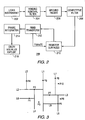
- FIG. 2 there is shown high level block diagram showing an information processing system 200 using an embodiment of the invention.
- the system 200 comprises a source 202 of topographical data points. These points are preferably a plurality of three-dimensional (3D) topographical point values provided by a LIDAR instrument 102 as discussed with respect to FIG. 1 .
- 3D three-dimensional
- the LIDAR instrument 202 creates a plurality of frames (or volumes) of images of points in a conventional manner.
- Each frame comprises the points collected by the sensor 103 over a given period of time (an exposure) as the aircraft 104 moves over a terrain. In the preferred embodiment, this time period is one-third of a second and, with current instruments, that exposure results in collection of hundreds of thousands of points by the LIDAR sensor 103.
- Each point is defined by a set of three-dimensional coordinates (x, y, z).
- One way that the present system improves on the performance of the prior art is, at least in part, by using only data points representing the ground surface and a target 106 (if present) and not the obstructions at a height greater than a predetermined threshold (such as six feet) above the ground.
- a predetermined threshold such as six feet
- the data provided by the LIDAR instrument 102 may comprise an effect known as ringing (or corona effect). Ringing is caused by scattering of the light produced by a target area that causes a false return.
- a ringing removal filter (circuitry or program logic) 204 is used for filtering the received 3D topographical points to remove the ringing. Not all topographical data includes ringing. Therefore, the filter 204 is not always required. The ringing is removed by ignoring all data beyond a selected azimuth setting, thus eliminating any false images. The selection of the azimuth is governed by statistical data or determined heuristically.
- the use of the ringing removal filter 204 in system 200 increases the signal to noise ratio at the output of the filter 204.
- the details of an example of a ringing filter are discussed in a patent application being filed concurrently herewith under the docket number GCSD-1526.
- the output provided by the ringing noise removal filter 204 is received at a ground finder 206.
- the ground finder 206 is used for finding a ground surface using the plurality of raw topographical points (e.g., from the LIDAR instrument 102) and their coordinates and providing a plurality of ground points representing a plurality of frames representing patches of the ground surface and the target 106.
- the ground finder 206 finds the ground by extracting ground points from its input and filtering out above-ground obstruction points such as those from the top of the trees.
- the number of LIDAR pulses that reach the ground through the trees and other foliage is much smaller than those emitted by the LIDAR source (or emitter). Therefore, the points of light from the ground (ground points) detected at the LIDAR sensor is commensurately smaller than the total number received from the totality of the terrain below the aircraft 104.
- the ground finder 206 thus extracts a ground surface shell (a set of points defining a three-dimensional surface) from the topographical data provided at the output of the ringing removal filter 204.
- the output of the ground finder 206 comprises a set of data representing a ground surface that includes the target 106.
- the ground points are determined by isolating them from the above-ground obstructions provided by the trees and other foliage.
- the ground finder 206 also operates to make sure that the ground is continuous so that there are no large changes in the topography. This is accomplished by creating a two-dimensional (2D) grid for the ground surface and determining the height of the ground at each grid component. Each grid component preferably represents a square part of the ground that is one meter on each side. Once this data is collected for the entire grid, the ground finder 206 eliminates points that appear to be out of place or which are based on insufficient data. The decision on which points to eliminate is based on artifacts programmed into the ground finder 206. The ground finder 206 is further programmed to ignore any points higher than a predetermined height (e.g., the height of a person, such as six feet) when calculating the contour of the ground surface. The predetermined height is determined by rule-based statistics. That is done to eliminate any structures that are not likely to be part of the ground. Thus, the output of the ground finder 206 provides a more faithful representation of the actual ground surface than systems using the treetop data.
- the output of the ground finder 206 is provided to a competitive filter 208.
- the competitive filter 208 is used to work on ground surface data (ground points) provided by the ground finder 206.
- the ground points are filtered using the competitive filter to obtain a 3D shell of digital elevation model (DEM) points.
- the competitive filter 208 filters ground surface data not tied to geospatial coordinates such as the data collected by the LIDAR instrument 202.
- the filter 208 works by performing a polynomial fit of predetermined order for each frame of points. This is done by determining which polynomial best represents the set of points in the frame.
- One example is a first order polynomial (a tilted plane) and the other is a numeric average (zero order).
- the average and the tilted plane compete for the best fit in any given frame of points.
- Other embodiments may utilize higher order polynomials.
- a method for fitting polynomials in frames is discussed in United States Patent Application, Serial Number 09/827,305 , the disclosure of which is hereby incorporated herein by reference in its entirety.
- each frame is a micro frame that covers a patch constituting a small portion of the total area produced by registration.
- the output of the competitive filter 208 is a contour comprising a plurality of (e.g., thirty) planes, one for each frame acquired.
- An optimal estimate of the ground surface allows for obscuration by the trees and foliage to produce an image of a partially obscured target.
- the output is a set of unregistered DEM surfaces.
- each surface is a ground surface; however it should be appreciated that the method and system of the invention can be used on any surface of a target object.
- the data produced by the competitive filter 208 DEM is not suitable for rendering an image that is useful to a user of the system 200.
- the registration is performed by an iterative process performed by blocks 210 (a registration engine) and 212 (a rigid transform engine).
- blocks 210 a registration engine
- 212 a rigid transform engine
- To obtain a 3D representation of the ground surface several sets of data (frames) are automatically pieced together to create an image of an entire target area or surface. Each set of data (or frame) is taken from a different perspective providing a different view of the surface features.
- Registration determines the relative positions of each of the points representing the surface as the sensor 103 moves over that surface. Thus different views of the surface area are aligned with each other by performing a translation and rotation of each frame to fit an adjacent frame or frames.
- Block 210 aligns points in adjacent frames. It does this by finding in a second frame the closest point for each of a plurality of points in a first frame. Once the closest point is found the points are aligned such that the frames make a good fit representing the registered model or image. This is known as a pair wise process. Each iteration of the process produces a better fit and the process continues until an optimum alignment is realized. This is accomplished by determining a computation cost associated with each rotation and translation of each frame to fit other frames. Using the information (matches between adjacent frames) collected in each iteration, subsequent iterations correct the alignment until an abort criterion is reached. This criterion can be the completion of a number of iterations or the accomplishment of a predetermined goal.
- Block 212 receives information on the alignment of points produced at block 210 during each iteration.
- Processor logic in block 212 uses the information provided by block 210 to determine transforms (i.e., angles and displacements) for each frame as they are fitted together.
- the output of block 212 is thus a set of angles and displacements ( ⁇ x, ⁇ y, ⁇ z, ⁇ , ⁇ , and ⁇ ) for the frames to be pieced together.
- the frame integrator block 214 receives the output of the rigid transform block 212 and integrates all of the DEM points produced by the competitive filter 208 according to the rigid transform information.
- the iterative process is repeated several (e.g., five) times to determine an optimum rotation and translation for the frames.
- Each transformation is a rigid transformation.
- a transform is said to be rigid if it preserves the distances between corresponding points.
- the frame integrator block 214 integration of the registered volumes produced by block 212 is performed and the result is cropped to a size and shape suitable for presentation and then it is visually exploited at block 216 to show the structure of the target.
- the result is a 3D model that is displayed quickly.
- a target such as the tank 106 hidden under the treetops as shown in FIG. 1 is depicted without the obscuring effect of the canopy of trees over the tank 106.
- the speed of the registration process is critical in many applications such a locating a hidden target such as a tank 106 in a combat environment.
- One way to speed up the process is to improve the speed of the search for corresponding points from frame to frame. This can be accomplished by using any of several well-known k-D tree algorithms.
- the data points from each frame are mapped into a tree structure such that the entire set of points in an adjacent frame do not have to be searched to find the closest point for a given point in a first frame.
- An example of a k-D tree algorithm is found at the web site located at http://www.rolemaker.dk/nonRoleMaker/uni/algogem/kdtree.htm.
- the region is split into two regions, each region containing half of the points. This process is repeated until each point is in its own region by itself.
- the region is split into two regions, each region containing half of the points. This process is repeated until each point is in its own region by itself.
- 8 points if one starts with 8 points and is looking for a particular point, cut it down to four points by querying which half it is located in, then down to two, and finally to one. This was just three steps, which is easier than asking all eight points. The difference is specially huge the more points there are. If there are 256 points, one can usually find a point in eight tries instead of 256.
- the registration engine 210 generates lines L1-L8. These lines are used to build the k-D tree and shown in FIG. 4 .
- the k-D tree is created by recursively dividing the points P1-P10 in x and y directions.
- each line of FIG. 3 is represented by a node (circles) and each point (rectangle) is connected to a node.
- the tree is used to reduce the searching time required to find the point closest to any given point. For example, if searching for the point closest to P10, one would traverse node L1 to L3, and then to L7 and consider only point P9 and not P1. Note that this example is 2D, but our application uses 3D points.
- FIG. 5 is a graph of a plurality of points illustrating the benefit of statistical distance versus Euclidean distance.
- Points shown as Os are from a LIDAR-produced frame A and points shown as Xs are from a LIDAR-produced frame B. Assume that these frames or volumes are overlapping. We do not know ab initio which points in frame A align with which points in frame B. We begin by comparing the coordinates for each pair of points to be aligned. For any given point in frame A we consider other points within an area in frame B. The distances between any given pair of points is represented as circles or ellipses. The circles represent Euclidean distances and the ellipses represent the Mahalanobis distances.
- the Mahalanobis distance is used to align points up and down (i.e., along the z axis). This process recognizes the observed fact that points appear farther in the z direction than they actually are. By aligning points using the elliptical areas to locate corresponding points in other frames we achieve a more accurate model than by merely using Euclidean distances represented by the circles.
Landscapes
- Physics & Mathematics (AREA)
- Engineering & Computer Science (AREA)
- General Physics & Mathematics (AREA)
- Bioinformatics & Computational Biology (AREA)
- Electromagnetism (AREA)
- Evolutionary Biology (AREA)
- Probability & Statistics with Applications (AREA)
- Computer Vision & Pattern Recognition (AREA)
- Life Sciences & Earth Sciences (AREA)
- Theoretical Computer Science (AREA)
- Bioinformatics & Cheminformatics (AREA)
- Radar, Positioning & Navigation (AREA)
- Remote Sensing (AREA)
- Image Processing (AREA)
- Image Analysis (AREA)
- Optical Radar Systems And Details Thereof (AREA)
- Processing Or Creating Images (AREA)
- Aiming, Guidance, Guns With A Light Source, Armor, Camouflage, And Targets (AREA)
Abstract
Description
- In generating a complete digital model of a multidimensional object, such as a varied geographic terrain, it is necessary to combine several overlapping range images (also known as frames or volumes of data points) taken from different perspectives. The frames are pieced together using a process known as registration to produce a multidimensional model of the object. In a registration process the required translation and rotation of the different frames is determined. This process uses six parameters: Δx, Δy, Δz, Δω , Δk , and Δφ, where the first three parameters relate to the translation of the respective x, y, and z coordinates and the second three parameters, each relate to rotation on each of the three respective x, y, and z axes. Known methods of registering frames comprising large numbers of data points from different and overlapping perspectives of an object are computationally intensive and hence time consuming. However, many applications of the registration technology require a fast response from the time that the frames are acquired. Therefore, there is a need for a faster and more robust system for registering multidimensional data points.
- Known methods of topographical point collection include imaging Laser RADAR (LIDAR) and IFSAR (Interferometric Synthetic Aperture Radar). Referring to
FIG. 1 , there is shown an example of anairborne LIDAR system 100. Thesystem 100 comprises a LIDARinstrument 102 mounted on the bottom of anaircraft 104. Below the aircraft is an area comprising a ground surface partially obscured by a canopy formed by trees and other foliage obstructing the view of the ground (earth) from an aerial view. The LIDARinstrument 102 emits a plurality of laser light pulses which are directed toward the ground. Theinstrument 102 comprises asensor 103 that detects the reflections/scattering of the pulses. The LIDARinstrument 102 provides data including elevation versus position information from a single image. It should be noted however, that multiple frames or portions of the area from different perspectives are used to generate the image. The tree canopy overlying the terrain also results in significant obscuration of targets (e.g. tank 106) under the tree canopy. The points received by thesensor 103 ofinstrument 102 from the ground and thetarget 106 are thus sparse. Hence, a robust system for processing the points is required in order to generate an accurate three-dimensional image. Moreover, to be of the most tactical and strategic value, an image of the ground wherein thetarget 106 can be perceived easily must be available quickly. - Document XP002529640, NISHINO K ET AL: "Robust simultaneous registration of multiple range images" PROCEEDINGS OF THE FIFTH ASIAN CONFERENCE ON COMPUTER VISION ASIAN FEDERATION OF COMPUTER VISION SOC CLAYTON, VIC., AUSTRALIA, discloses an approach to registration of multiple point cloud range images. The approach is based on simultaneous strategy, using points as matching units and using point-to-point distance metric. The framework disclosed therein designed not to use secondary information, such as surface metrics.
- According to an embodiment of the invention a method for registering multi-dimensional topographical data points comprises steps of: receiving a plurality of digital elevation model points representing a plurality of overlapping frames of a geographical area; finding for each of a plurality of points in a first frame a corresponding closest point in a plurality of subsequent frames; determining a rotation and translation transformation for each frame; determining a cost for performing each rotation and translation transformation; and iterating the above process for additional frames for a number of times or until an abort criterion is reached to optimize the cost of registering the frames. The above-described method can also be carried out by a specialized or programmable information processing system or as a set of instructions in a computer-readable medium such as a CD ROM or DVD or the like.
-
-
FIG. 1 is a depiction of an airborne LIDAR instrument for processing images of a tree-covered terrain concealing a target. -
FIG. 2 is a high level block diagram showing an information processing system according to an embodiment of the invention. -
FIG. 3 is a two-dimensional set of points representing a surface for one frame such as a frame of LIDAR points. -
FIG. 4 is a depiction of a k-D tree used to search for the closest points. -
FIG. 5 is a graph of a plurality of points illustrating the benefit of statistical distance versus Euclidean distance. - Referring to
FIG. 2 , there is shown high level block diagram showing aninformation processing system 200 using an embodiment of the invention. Thesystem 200 comprises asource 202 of topographical data points. These points are preferably a plurality of three-dimensional (3D) topographical point values provided by aLIDAR instrument 102 as discussed with respect toFIG. 1 . - The LIDAR
instrument 202 creates a plurality of frames (or volumes) of images of points in a conventional manner. Each frame comprises the points collected by thesensor 103 over a given period of time (an exposure) as theaircraft 104 moves over a terrain. In the preferred embodiment, this time period is one-third of a second and, with current instruments, that exposure results in collection of hundreds of thousands of points by the LIDARsensor 103. Each point is defined by a set of three-dimensional coordinates (x, y, z). - One way that the present system improves on the performance of the prior art is, at least in part, by using only data points representing the ground surface and a target 106 (if present) and not the obstructions at a height greater than a predetermined threshold (such as six feet) above the ground. Using only the ground points greatly reduces the number of points that are to be down-linked and processed and thus reduces the time required to produce a model of the terrain.
- The data provided by the LIDAR
instrument 102 may comprise an effect known as ringing (or corona effect). Ringing is caused by scattering of the light produced by a target area that causes a false return. A ringing removal filter (circuitry or program logic) 204 is used for filtering the received 3D topographical points to remove the ringing. Not all topographical data includes ringing. Therefore, thefilter 204 is not always required. The ringing is removed by ignoring all data beyond a selected azimuth setting, thus eliminating any false images. The selection of the azimuth is governed by statistical data or determined heuristically. The use of theringing removal filter 204 insystem 200 increases the signal to noise ratio at the output of thefilter 204. The details of an example of a ringing filter are discussed in a patent application being filed concurrently herewith under the docket number GCSD-1526. - The output provided by the ringing
noise removal filter 204 is received at aground finder 206. Theground finder 206 is used for finding a ground surface using the plurality of raw topographical points (e.g., from the LIDAR instrument 102) and their coordinates and providing a plurality of ground points representing a plurality of frames representing patches of the ground surface and thetarget 106. Theground finder 206 finds the ground by extracting ground points from its input and filtering out above-ground obstruction points such as those from the top of the trees. As expected, the number of LIDAR pulses that reach the ground through the trees and other foliage is much smaller than those emitted by the LIDAR source (or emitter). Therefore, the points of light from the ground (ground points) detected at the LIDAR sensor is commensurately smaller than the total number received from the totality of the terrain below theaircraft 104. - The
ground finder 206 thus extracts a ground surface shell (a set of points defining a three-dimensional surface) from the topographical data provided at the output of theringing removal filter 204. The output of theground finder 206 comprises a set of data representing a ground surface that includes thetarget 106. The ground points are determined by isolating them from the above-ground obstructions provided by the trees and other foliage. - The
ground finder 206 also operates to make sure that the ground is continuous so that there are no large changes in the topography. This is accomplished by creating a two-dimensional (2D) grid for the ground surface and determining the height of the ground at each grid component. Each grid component preferably represents a square part of the ground that is one meter on each side. Once this data is collected for the entire grid, theground finder 206 eliminates points that appear to be out of place or which are based on insufficient data. The decision on which points to eliminate is based on artifacts programmed into theground finder 206. Theground finder 206 is further programmed to ignore any points higher than a predetermined height (e.g., the height of a person, such as six feet) when calculating the contour of the ground surface. The predetermined height is determined by rule-based statistics. That is done to eliminate any structures that are not likely to be part of the ground. Thus, the output of theground finder 206 provides a more faithful representation of the actual ground surface than systems using the treetop data. - The output of the
ground finder 206 is provided to acompetitive filter 208. Thecompetitive filter 208 is used to work on ground surface data (ground points) provided by theground finder 206. The ground points are filtered using the competitive filter to obtain a 3D shell of digital elevation model (DEM) points. Thecompetitive filter 208 filters ground surface data not tied to geospatial coordinates such as the data collected by theLIDAR instrument 202. Thefilter 208 works by performing a polynomial fit of predetermined order for each frame of points. This is done by determining which polynomial best represents the set of points in the frame. One example is a first order polynomial (a tilted plane) and the other is a numeric average (zero order). In the preferred embodiment, the average and the tilted plane (respectively, zero and first order polynomials) compete for the best fit in any given frame of points. Other embodiments may utilize higher order polynomials. A method for fitting polynomials in frames is discussed in United States Patent Application, Serial Number09/827,305 - Thus, for every frame of points the
filter 208 determines a tilted plane that fits the points in that frame. Each frame is a micro frame that covers a patch constituting a small portion of the total area produced by registration. The output of thecompetitive filter 208 is a contour comprising a plurality of (e.g., thirty) planes, one for each frame acquired. An optimal estimate of the ground surface allows for obscuration by the trees and foliage to produce an image of a partially obscured target. Once each frame is processed by thefilter 208 the output is a set of unregistered DEM surfaces. In this embodiment each surface is a ground surface; however it should be appreciated that the method and system of the invention can be used on any surface of a target object. - The data produced by the
competitive filter 208 DEM is not suitable for rendering an image that is useful to a user of thesystem 200. To produce a viewable image we must first complete a registration process. In the preferred embodiment the registration is performed by an iterative process performed by blocks 210 (a registration engine) and 212 (a rigid transform engine). In this embodiment, to obtain a 3D representation of the ground surface, several sets of data (frames) are automatically pieced together to create an image of an entire target area or surface. Each set of data (or frame) is taken from a different perspective providing a different view of the surface features. Registration determines the relative positions of each of the points representing the surface as thesensor 103 moves over that surface. Thus different views of the surface area are aligned with each other by performing a translation and rotation of each frame to fit an adjacent frame or frames. -
Block 210 aligns points in adjacent frames. It does this by finding in a second frame the closest point for each of a plurality of points in a first frame. Once the closest point is found the points are aligned such that the frames make a good fit representing the registered model or image. This is known as a pair wise process. Each iteration of the process produces a better fit and the process continues until an optimum alignment is realized. This is accomplished by determining a computation cost associated with each rotation and translation of each frame to fit other frames. Using the information (matches between adjacent frames) collected in each iteration, subsequent iterations correct the alignment until an abort criterion is reached. This criterion can be the completion of a number of iterations or the accomplishment of a predetermined goal. In this embodiment, we perform the closest point search for each point in a first frame to locate closest points in more than one other frame by entering observations from each iteration into a matrix and then solving the matrix at once so that all transformations are performed substantially simultaneously (i.e., an n-wise process). -
Block 212 receives information on the alignment of points produced atblock 210 during each iteration. Processor logic inblock 212 uses the information provided byblock 210 to determine transforms (i.e., angles and displacements) for each frame as they are fitted together. The output ofblock 212 is thus a set of angles and displacements (Δx, Δy, Δz, Δω , Δκ , and Δφ) for the frames to be pieced together. - The
frame integrator block 214 receives the output of therigid transform block 212 and integrates all of the DEM points produced by thecompetitive filter 208 according to the rigid transform information. - In the preferred embodiment the iterative process is repeated several (e.g., five) times to determine an optimum rotation and translation for the frames. We preferably use the algorithm presented in J.A. Williams and M. Bennamoun, "Simultaneous Registration of Multiple Point Sets Using Orthonormal Matrices" Proc. IEEE Int. Conf. on Acoustics, Speech and Signal Processing (ICASSP Jun. 2000) at pp. 2199 - 2202, the disclosure of which is hereby incorporated herein by reference.
- The iterated transformations discussed above are performed at
block 212. Each transformation is a rigid transformation. A transform is said to be rigid if it preserves the distances between corresponding points. - In the
frame integrator block 214, integration of the registered volumes produced byblock 212 is performed and the result is cropped to a size and shape suitable for presentation and then it is visually exploited atblock 216 to show the structure of the target. The result is a 3D model that is displayed quickly. In the embodiment discussed herein a target such as thetank 106 hidden under the treetops as shown inFIG. 1 is depicted without the obscuring effect of the canopy of trees over thetank 106. - As discussed above, the speed of the registration process is critical in many applications such a locating a hidden target such as a
tank 106 in a combat environment. One way to speed up the process is to improve the speed of the search for corresponding points from frame to frame. This can be accomplished by using any of several well-known k-D tree algorithms. Thus, the data points from each frame are mapped into a tree structure such that the entire set of points in an adjacent frame do not have to be searched to find the closest point for a given point in a first frame. An example of a k-D tree algorithm is found at the web site located at http://www.rolemaker.dk/nonRoleMaker/uni/algogem/kdtree.htm. - Referring to
FIG. 3 , there is shown a set of points (P1 - P10) representing a surface for one frame such as a frame of LIDAR points. At each step, the region is split into two regions, each region containing half of the points. This process is repeated until each point is in its own region by itself. As an example, if one starts with 8 points and is looking for a particular point, cut it down to four points by querying which half it is located in, then down to two, and finally to one. This was just three steps, which is easier than asking all eight points. The difference is specially huge the more points there are. If there are 256 points, one can usually find a point in eight tries instead of 256. - The
registration engine 210 generates lines L1-L8. These lines are used to build the k-D tree and shown inFIG. 4 . The k-D tree is created by recursively dividing the points P1-P10 in x and y directions. In the k-D tree each line ofFIG. 3 is represented by a node (circles) and each point (rectangle) is connected to a node. The tree is used to reduce the searching time required to find the point closest to any given point. For example, if searching for the point closest to P10, one would traverse node L1 to L3, and then to L7 and consider only point P9 and not P1. Note that this example is 2D, but our application uses 3D points. -
FIG. 5 is a graph of a plurality of points illustrating the benefit of statistical distance versus Euclidean distance. Points shown as Os are from a LIDAR-produced frame A and points shown as Xs are from a LIDAR-produced frame B. Assume that these frames or volumes are overlapping. We do not know ab initio which points in frame A align with which points in frame B. We begin by comparing the coordinates for each pair of points to be aligned. For any given point in frame A we consider other points within an area in frame B. The distances between any given pair of points is represented as circles or ellipses. The circles represent Euclidean distances and the ellipses represent the Mahalanobis distances. The quantity r in theequation 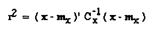
Claims (5)
- A system (200) for registering a set of frames of 3-dimensional digital elevation model points which include both ground points representing a 3-dimensional surface and obstruction points which represent an obstruction lying above the 3-dimensional surface and are positionally interspersed among the ground points, the system comprising:a ground finder (206) for isolating the obstruction points from the ground points;a competitive filter (208) for obtaining a ground surface shell from a plurality of ground points provided by said ground finder, said ground surface shell including a representation of each respective one of said frames;a registration engine coupled to said competitive filter for finding for each point in a first frame a corresponding closest point in each of a plurality of subsequent frames of said ground surface shell;a processor for determining a rotation and translation transformation for each of the plurality of subsequent frames and for determining a cost for performing each rotation and translation transformation; anda logic routine for repeating the determinations of rotation and translation and cost of additional frames until an abort criterion is reached.
- The system (200) of claim 1, further comprising logic for applying a rigid transform to the frames using cost determined by the processor.
- The system (200) of claim 1, further comprising a k-D tree representing the points of each frame for searching in the subsequent frames for the point closest to each of the points in the first frame.
- The system (200) of claim 1, further comprising a frame integrator (214) for integrating the frames to provide an integrated surface representing the multi dimensional object.
- The system (200) of claim 1, further comprising a display for displaying the multi dimensional object.
Applications Claiming Priority (2)
| Application Number | Priority Date | Filing Date | Title |
|---|---|---|---|
| US10/892,047 US7567731B2 (en) | 2004-07-15 | 2004-07-15 | Method and system for simultaneously registering multi-dimensional topographical points |
| PCT/US2005/024117 WO2006019597A2 (en) | 2004-07-15 | 2005-07-07 | Method and system for simultaneously registering multi-dimensional topographical points |
Publications (3)
| Publication Number | Publication Date |
|---|---|
| EP1779292A2 EP1779292A2 (en) | 2007-05-02 |
| EP1779292A4 EP1779292A4 (en) | 2009-07-15 |
| EP1779292B1 true EP1779292B1 (en) | 2010-11-24 |
Family
ID=35599467
Family Applications (1)
| Application Number | Title | Priority Date | Filing Date |
|---|---|---|---|
| EP05770209A Expired - Lifetime EP1779292B1 (en) | 2004-07-15 | 2005-07-07 | Method and system for simultaneously registering multi-dimensional topographical points |
Country Status (10)
| Country | Link |
|---|---|
| US (1) | US7567731B2 (en) |
| EP (1) | EP1779292B1 (en) |
| JP (1) | JP2008506136A (en) |
| KR (1) | KR100922903B1 (en) |
| CN (1) | CN100568261C (en) |
| BR (1) | BRPI0513355A (en) |
| CA (1) | CA2573153C (en) |
| DE (1) | DE602005024972D1 (en) |
| TW (1) | TWI315497B (en) |
| WO (1) | WO2006019597A2 (en) |
Families Citing this family (21)
| Publication number | Priority date | Publication date | Assignee | Title |
|---|---|---|---|---|
| US8958654B1 (en) * | 2001-04-25 | 2015-02-17 | Lockheed Martin Corporation | Method and apparatus for enhancing three-dimensional imagery data |
| US7616828B2 (en) * | 2006-07-20 | 2009-11-10 | Harris Corporation | Geospatial modeling system providing geospatial model data target point filtering based upon radial line segments and related methods |
| US7764810B2 (en) * | 2006-07-20 | 2010-07-27 | Harris Corporation | Geospatial modeling system providing non-linear inpainting for voids in geospatial model terrain data and related methods |
| US7752018B2 (en) * | 2006-07-20 | 2010-07-06 | Harris Corporation | Geospatial modeling system providing building roof type identification features and related methods |
| US7760913B2 (en) | 2006-07-20 | 2010-07-20 | Harris Corporation | Geospatial modeling system providing non-linear in painting for voids in geospatial model frequency domain data and related methods |
| US7750902B2 (en) * | 2006-07-20 | 2010-07-06 | Harris Corporation | Geospatial modeling system providing non-linear inpainting for voids in geospatial model cultural feature data and related methods |
| US7456779B2 (en) * | 2006-08-31 | 2008-11-25 | Sierra Nevada Corporation | System and method for 3D radar image rendering |
| US7881913B2 (en) * | 2007-02-12 | 2011-02-01 | Harris Corporation | Exemplar/PDE-based technique to fill null regions and corresponding accuracy assessment |
| KR100836196B1 (en) | 2007-03-22 | 2008-06-09 | 인하대학교 산학협력단 | LIDARR Terrain Information Extraction Method Using Vegetation Transmission Characteristics |
| US8139863B1 (en) * | 2008-04-25 | 2012-03-20 | Hsu Shin-Yi | System for capturing, characterizing and visualizing lidar and generic image data |
| US8427505B2 (en) | 2008-11-11 | 2013-04-23 | Harris Corporation | Geospatial modeling system for images and related methods |
| US8471915B2 (en) | 2009-04-16 | 2013-06-25 | Raytheon Company | Self-correcting adaptive long-stare electro-optical system |
| FR2969802A1 (en) * | 2010-12-23 | 2012-06-29 | Thales Sa | METHOD FOR DETERMINING LOCATION ERROR IN A GEOREFERENCED IMAGE AND ASSOCIATED DEVICE |
| US11567201B2 (en) | 2016-03-11 | 2023-01-31 | Kaarta, Inc. | Laser scanner with real-time, online ego-motion estimation |
| US11573325B2 (en) | 2016-03-11 | 2023-02-07 | Kaarta, Inc. | Systems and methods for improvements in scanning and mapping |
| CN109313024B (en) | 2016-03-11 | 2022-06-17 | 卡尔塔股份有限公司 | Laser scanner with real-time online self-motion estimation |
| US10989542B2 (en) | 2016-03-11 | 2021-04-27 | Kaarta, Inc. | Aligning measured signal data with slam localization data and uses thereof |
| US10341565B2 (en) | 2016-05-10 | 2019-07-02 | Raytheon Company | Self correcting adaptive low light optical payload |
| WO2019099605A1 (en) | 2017-11-17 | 2019-05-23 | Kaarta, Inc. | Methods and systems for geo-referencing mapping systems |
| WO2019195270A1 (en) | 2018-04-03 | 2019-10-10 | Kaarta, Inc. | Methods and systems for real or near real-time point cloud map data confidence evaluation |
| WO2020009826A1 (en) | 2018-07-05 | 2020-01-09 | Kaarta, Inc. | Methods and systems for auto-leveling of point clouds and 3d models |
Family Cites Families (36)
| Publication number | Priority date | Publication date | Assignee | Title |
|---|---|---|---|---|
| JPH02211584A (en) * | 1989-02-13 | 1990-08-22 | Toshiba Corp | Graphic information processing system |
| US6400996B1 (en) | 1999-02-01 | 2002-06-04 | Steven M. Hoffberg | Adaptive pattern recognition based control system and method |
| US6081750A (en) | 1991-12-23 | 2000-06-27 | Hoffberg; Steven Mark | Ergonomic man-machine interface incorporating adaptive pattern recognition based control system |
| US6418424B1 (en) | 1991-12-23 | 2002-07-09 | Steven M. Hoffberg | Ergonomic man-machine interface incorporating adaptive pattern recognition based control system |
| US5901246A (en) | 1995-06-06 | 1999-05-04 | Hoffberg; Steven M. | Ergonomic man-machine interface incorporating adaptive pattern recognition based control system |
| US5875108A (en) | 1991-12-23 | 1999-02-23 | Hoffberg; Steven M. | Ergonomic man-machine interface incorporating adaptive pattern recognition based control system |
| US5670935A (en) * | 1993-02-26 | 1997-09-23 | Donnelly Corporation | Rearview vision system for vehicle including panoramic view |
| JPH06313715A (en) * | 1993-04-30 | 1994-11-08 | Chubu Electric Power Co Inc | Method and apparatus for measuring profile and separation of section on ground |
| US5649032A (en) | 1994-11-14 | 1997-07-15 | David Sarnoff Research Center, Inc. | System for automatically aligning images to form a mosaic image |
| EP0721286A3 (en) | 1995-01-09 | 2000-07-26 | Matsushita Electric Industrial Co., Ltd. | Video signal decoding apparatus with artifact reduction |
| US5644386A (en) * | 1995-01-11 | 1997-07-01 | Loral Vought Systems Corp. | Visual recognition system for LADAR sensors |
| US6405132B1 (en) | 1997-10-22 | 2002-06-11 | Intelligent Technologies International, Inc. | Accident avoidance system |
| US6526352B1 (en) | 2001-07-19 | 2003-02-25 | Intelligent Technologies International, Inc. | Method and arrangement for mapping a road |
| US5751838A (en) | 1996-01-26 | 1998-05-12 | Nec Research Institute, Inc. | Correction of camera motion between two image frames |
| US5988862A (en) | 1996-04-24 | 1999-11-23 | Cyra Technologies, Inc. | Integrated system for quickly and accurately imaging and modeling three dimensional objects |
| US5870105A (en) * | 1996-05-31 | 1999-02-09 | Hewlett-Packard Company | System and method for local storage of image data during object to image mapping |
| US6173087B1 (en) * | 1996-11-13 | 2001-01-09 | Sarnoff Corporation | Multi-view image registration with application to mosaicing and lens distortion correction |
| US6420698B1 (en) | 1997-04-24 | 2002-07-16 | Cyra Technologies, Inc. | Integrated system for quickly and accurately imaging and modeling three-dimensional objects |
| US6512857B1 (en) * | 1997-05-09 | 2003-01-28 | Sarnoff Corporation | Method and apparatus for performing geo-spatial registration |
| JPH10318743A (en) * | 1997-05-19 | 1998-12-04 | Nakanihon Koku Kk | Method and apparatus for surveying by using flying object |
| JP3515678B2 (en) * | 1997-06-30 | 2004-04-05 | 朝日航洋株式会社 | Measurement system and method and airborne laser measurement device |
| JPH11248443A (en) * | 1997-12-12 | 1999-09-17 | Nec Corp | Tree height measuring system |
| JP2000215317A (en) * | 1998-11-16 | 2000-08-04 | Sony Corp | Image processing method and image processor |
| JP2000180100A (en) * | 1998-12-17 | 2000-06-30 | Nec Corp | Nighttime unmanned reconnaissance device |
| US6711293B1 (en) | 1999-03-08 | 2004-03-23 | The University Of British Columbia | Method and apparatus for identifying scale invariant features in an image and use of same for locating an object in an image |
| US6587601B1 (en) | 1999-06-29 | 2003-07-01 | Sarnoff Corporation | Method and apparatus for performing geo-spatial registration using a Euclidean representation |
| US7019777B2 (en) * | 2000-04-21 | 2006-03-28 | Flight Landata, Inc. | Multispectral imaging system with spatial resolution enhancement |
| US6738532B1 (en) * | 2000-08-30 | 2004-05-18 | The Boeing Company | Image registration using reduced resolution transform space |
| US6654690B2 (en) | 2001-04-05 | 2003-11-25 | Harris Corporation | Automated method for making a topographical model and related system |
| JP2002341031A (en) * | 2001-05-11 | 2002-11-27 | Daiei Dream Kk | Forming method of three-dimensional model and three- dimensional scanner system using laser radar |
| WO2003067276A2 (en) * | 2002-02-04 | 2003-08-14 | Bae Systems Information And Electronic Systems Integration Inc. | Reentry vehicle interceptor with ir and variable fov laser radar |
| JP4177634B2 (en) * | 2002-10-21 | 2008-11-05 | 株式会社パスコ | Laser data edge matching method |
| US6864828B1 (en) * | 2003-02-18 | 2005-03-08 | Lockheed Martin Corporation | Method and apparatus for collection and processing of interferometric synthetic aperture radar data |
| US7242460B2 (en) * | 2003-04-18 | 2007-07-10 | Sarnoff Corporation | Method and apparatus for automatic registration and visualization of occluded targets using ladar data |
| US20050089213A1 (en) * | 2003-10-23 | 2005-04-28 | Geng Z. J. | Method and apparatus for three-dimensional modeling via an image mosaic system |
| US8175412B2 (en) * | 2004-02-17 | 2012-05-08 | Yeda Research & Development Co. Ltd. | Method and apparatus for matching portions of input images |
-
2004
- 2004-07-15 US US10/892,047 patent/US7567731B2/en active Active
-
2005
- 2005-07-07 KR KR1020077001035A patent/KR100922903B1/en not_active Expired - Fee Related
- 2005-07-07 CA CA2573153A patent/CA2573153C/en not_active Expired - Fee Related
- 2005-07-07 EP EP05770209A patent/EP1779292B1/en not_active Expired - Lifetime
- 2005-07-07 DE DE602005024972T patent/DE602005024972D1/en not_active Expired - Lifetime
- 2005-07-07 BR BRPI0513355-6A patent/BRPI0513355A/en not_active IP Right Cessation
- 2005-07-07 CN CNB2005800238945A patent/CN100568261C/en not_active Expired - Fee Related
- 2005-07-07 WO PCT/US2005/024117 patent/WO2006019597A2/en not_active Ceased
- 2005-07-07 JP JP2007521507A patent/JP2008506136A/en active Pending
- 2005-07-15 TW TW094124186A patent/TWI315497B/en not_active IP Right Cessation
Also Published As
| Publication number | Publication date |
|---|---|
| CA2573153A1 (en) | 2006-02-23 |
| TWI315497B (en) | 2009-10-01 |
| EP1779292A4 (en) | 2009-07-15 |
| US20060013443A1 (en) | 2006-01-19 |
| EP1779292A2 (en) | 2007-05-02 |
| CA2573153C (en) | 2011-09-06 |
| KR20070037618A (en) | 2007-04-05 |
| US7567731B2 (en) | 2009-07-28 |
| JP2008506136A (en) | 2008-02-28 |
| BRPI0513355A (en) | 2008-05-06 |
| CN100568261C (en) | 2009-12-09 |
| WO2006019597A3 (en) | 2006-05-04 |
| KR100922903B1 (en) | 2009-10-22 |
| WO2006019597A2 (en) | 2006-02-23 |
| CN1985264A (en) | 2007-06-20 |
| TW200620138A (en) | 2006-06-16 |
| DE602005024972D1 (en) | 2011-01-05 |
Similar Documents
| Publication | Publication Date | Title |
|---|---|---|
| US7298891B2 (en) | Bare earth digital elevation model extraction for three-dimensional registration from topographical points | |
| US7567731B2 (en) | Method and system for simultaneously registering multi-dimensional topographical points | |
| Persson et al. | Visualization and analysis of full-waveform airborne laser scanner data | |
| JP4926281B2 (en) | A method of recording multiple frames of a cloud-like 3D data point cloud for a target. | |
| Hebert | Outdoor scene analysis using range data | |
| US8483425B2 (en) | Geospatial information creating system and geospatial information creating method | |
| US20090232355A1 (en) | Registration of 3d point cloud data using eigenanalysis | |
| AU2018212700A1 (en) | Apparatus, method, and system for alignment of 3D datasets | |
| CN111209828B (en) | Method and system for extracting building roof vertex from airborne laser radar point cloud | |
| JP7820316B2 (en) | Systems and methods for air-to-ground alignment | |
| CN109492606A (en) | Multispectral vector picture capturing method and system, three dimensional monolithic method and system | |
| Awad | Toward robust segmentation results based on fusion methods for very high resolution optical image and lidar data | |
| US7571081B2 (en) | System and method for efficient visualization and comparison of LADAR point data to detailed CAD models of targets | |
| KR20220061734A (en) | Terrain scanning device using lidar device | |
| Sihvo et al. | Tree detection around forest harvester based on onboard LiDAR measurements | |
| Douillard et al. | Fft-based terrain segmentation for underwater mapping | |
| RU2778076C1 (en) | Method for building a digital surface model based on data from space stereo imaging | |
| Beumier et al. | Building change detection by histogram classification | |
| Sun | Evaluating the quality of ground surfaces generated from Terrestrial Laser Scanning (TLS) data | |
| de Oliveira et al. | Using hyperspectral frame images from unmanned airborne vehicle for detailed measurement of boreal forest 3D structure | |
| Dold et al. | Analysis of score functions for the automatic registration of terrestrial laser scans | |
| Oliveira et al. | Using Hyperspectral Frame Images from Unmanned Airborne Vehicle for Detailed Measurement of Boreal Forest 3D Structure | |
| Swirski et al. | Detection and delineation of buildings from airborne ladar measurements |
Legal Events
| Date | Code | Title | Description |
|---|---|---|---|
| PUAI | Public reference made under article 153(3) epc to a published international application that has entered the european phase |
Free format text: ORIGINAL CODE: 0009012 |
|
| 17P | Request for examination filed |
Effective date: 20070207 |
|
| AK | Designated contracting states |
Kind code of ref document: A2 Designated state(s): DE FR GB |
|
| RBV | Designated contracting states (corrected) |
Designated state(s): DE FR GB |
|
| DAX | Request for extension of the european patent (deleted) | ||
| A4 | Supplementary search report drawn up and despatched |
Effective date: 20090615 |
|
| GRAP | Despatch of communication of intention to grant a patent |
Free format text: ORIGINAL CODE: EPIDOSNIGR1 |
|
| GRAS | Grant fee paid |
Free format text: ORIGINAL CODE: EPIDOSNIGR3 |
|
| GRAA | (expected) grant |
Free format text: ORIGINAL CODE: 0009210 |
|
| AK | Designated contracting states |
Kind code of ref document: B1 Designated state(s): DE FR GB |
|
| REG | Reference to a national code |
Ref country code: GB Ref legal event code: FG4D |
|
| REF | Corresponds to: |
Ref document number: 602005024972 Country of ref document: DE Date of ref document: 20110105 Kind code of ref document: P |
|
| PLBE | No opposition filed within time limit |
Free format text: ORIGINAL CODE: 0009261 |
|
| STAA | Information on the status of an ep patent application or granted ep patent |
Free format text: STATUS: NO OPPOSITION FILED WITHIN TIME LIMIT |
|
| 26N | No opposition filed |
Effective date: 20110825 |
|
| REG | Reference to a national code |
Ref country code: DE Ref legal event code: R097 Ref document number: 602005024972 Country of ref document: DE Effective date: 20110825 |
|
| PGFP | Annual fee paid to national office [announced via postgrant information from national office to epo] |
Ref country code: GB Payment date: 20120725 Year of fee payment: 8 |
|
| PGFP | Annual fee paid to national office [announced via postgrant information from national office to epo] |
Ref country code: FR Payment date: 20120731 Year of fee payment: 8 Ref country code: DE Payment date: 20120727 Year of fee payment: 8 |
|
| GBPC | Gb: european patent ceased through non-payment of renewal fee |
Effective date: 20130707 |
|
| REG | Reference to a national code |
Ref country code: DE Ref legal event code: R119 Ref document number: 602005024972 Country of ref document: DE Effective date: 20140201 |
|
| REG | Reference to a national code |
Ref country code: FR Ref legal event code: ST Effective date: 20140331 |
|
| PG25 | Lapsed in a contracting state [announced via postgrant information from national office to epo] |
Ref country code: GB Free format text: LAPSE BECAUSE OF NON-PAYMENT OF DUE FEES Effective date: 20130707 Ref country code: DE Free format text: LAPSE BECAUSE OF NON-PAYMENT OF DUE FEES Effective date: 20140201 |
|
| PG25 | Lapsed in a contracting state [announced via postgrant information from national office to epo] |
Ref country code: FR Free format text: LAPSE BECAUSE OF NON-PAYMENT OF DUE FEES Effective date: 20130731 |