EP1777724A1 - Electric junction box - Google Patents
Electric junction box Download PDFInfo
- Publication number
- EP1777724A1 EP1777724A1 EP06021844A EP06021844A EP1777724A1 EP 1777724 A1 EP1777724 A1 EP 1777724A1 EP 06021844 A EP06021844 A EP 06021844A EP 06021844 A EP06021844 A EP 06021844A EP 1777724 A1 EP1777724 A1 EP 1777724A1
- Authority
- EP
- European Patent Office
- Prior art keywords
- input
- bus bar
- output
- case
- fuse
- Prior art date
- Legal status (The legal status is an assumption and is not a legal conclusion. Google has not performed a legal analysis and makes no representation as to the accuracy of the status listed.)
- Granted
Links
Images

Classifications
-
- H—ELECTRICITY
- H01—ELECTRIC ELEMENTS
- H01H—ELECTRIC SWITCHES; RELAYS; SELECTORS; EMERGENCY PROTECTIVE DEVICES
- H01H85/00—Protective devices in which the current flows through a part of fusible material and this current is interrupted by displacement of the fusible material when this current becomes excessive
- H01H85/02—Details
- H01H85/04—Fuses, i.e. expendable parts of the protective device, e.g. cartridges
- H01H85/041—Fuses, i.e. expendable parts of the protective device, e.g. cartridges characterised by the type
- H01H85/044—General constructions or structure of low voltage fuses, i.e. below 1000 V, or of fuses where the applicable voltage is not specified
-
- H—ELECTRICITY
- H01—ELECTRIC ELEMENTS
- H01H—ELECTRIC SWITCHES; RELAYS; SELECTORS; EMERGENCY PROTECTIVE DEVICES
- H01H85/00—Protective devices in which the current flows through a part of fusible material and this current is interrupted by displacement of the fusible material when this current becomes excessive
- H01H85/02—Details
- H01H85/20—Bases for supporting the fuse; Separate parts thereof
- H01H85/205—Electric connections to contacts on the base
-
- H—ELECTRICITY
- H01—ELECTRIC ELEMENTS
- H01H—ELECTRIC SWITCHES; RELAYS; SELECTORS; EMERGENCY PROTECTIVE DEVICES
- H01H85/00—Protective devices in which the current flows through a part of fusible material and this current is interrupted by displacement of the fusible material when this current becomes excessive
- H01H85/02—Details
- H01H85/0241—Structural association of a fuse and another component or apparatus
- H01H2085/025—Structural association with a binding post of a storage battery
-
- H—ELECTRICITY
- H01—ELECTRIC ELEMENTS
- H01H—ELECTRIC SWITCHES; RELAYS; SELECTORS; EMERGENCY PROTECTIVE DEVICES
- H01H85/00—Protective devices in which the current flows through a part of fusible material and this current is interrupted by displacement of the fusible material when this current becomes excessive
- H01H85/02—Details
- H01H85/20—Bases for supporting the fuse; Separate parts thereof
- H01H85/205—Electric connections to contacts on the base
- H01H2085/2055—Connections to bus bars in an installation with screw in type fuses or knife blade fuses
-
- H—ELECTRICITY
- H01—ELECTRIC ELEMENTS
- H01H—ELECTRIC SWITCHES; RELAYS; SELECTORS; EMERGENCY PROTECTIVE DEVICES
- H01H85/00—Protective devices in which the current flows through a part of fusible material and this current is interrupted by displacement of the fusible material when this current becomes excessive
- H01H85/02—Details
- H01H85/20—Bases for supporting the fuse; Separate parts thereof
- H01H85/205—Electric connections to contacts on the base
- H01H2085/206—Electric connections to contacts on the base being tappable, e.g. terminals on the fuse or base being arranged so as to permit an additional connector to be engaged therewith
-
- H—ELECTRICITY
- H01—ELECTRIC ELEMENTS
- H01H—ELECTRIC SWITCHES; RELAYS; SELECTORS; EMERGENCY PROTECTIVE DEVICES
- H01H85/00—Protective devices in which the current flows through a part of fusible material and this current is interrupted by displacement of the fusible material when this current becomes excessive
- H01H85/02—Details
- H01H85/20—Bases for supporting the fuse; Separate parts thereof
- H01H2085/2075—Junction box, having holders integrated with several other holders in a particular wiring layout
- H01H2085/208—Junction box, having holders integrated with several other holders in a particular wiring layout specially adapted for vehicles
-
- H—ELECTRICITY
- H01—ELECTRIC ELEMENTS
- H01H—ELECTRIC SWITCHES; RELAYS; SELECTORS; EMERGENCY PROTECTIVE DEVICES
- H01H85/00—Protective devices in which the current flows through a part of fusible material and this current is interrupted by displacement of the fusible material when this current becomes excessive
- H01H85/48—Protective devices wherein the fuse is carried or held directly by the base
- H01H85/52—Protective devices wherein the fuse is carried or held directly by the base the fuse being adapted for screwing into the base
-
- Y—GENERAL TAGGING OF NEW TECHNOLOGICAL DEVELOPMENTS; GENERAL TAGGING OF CROSS-SECTIONAL TECHNOLOGIES SPANNING OVER SEVERAL SECTIONS OF THE IPC; TECHNICAL SUBJECTS COVERED BY FORMER USPC CROSS-REFERENCE ART COLLECTIONS [XRACs] AND DIGESTS
- Y10—TECHNICAL SUBJECTS COVERED BY FORMER USPC
- Y10S—TECHNICAL SUBJECTS COVERED BY FORMER USPC CROSS-REFERENCE ART COLLECTIONS [XRACs] AND DIGESTS
- Y10S439/00—Electrical connectors
- Y10S439/908—Contact having two contact surfaces for electrical connection on opposite sides of insulative body
Definitions
- the present invention relates to an electric junction box which functions to distribute a power supply and protect a circuit.
- An electric junction box is installed on a vehicle such a motor vehicle for distribution of a power supply and protection of a circuit.
- a conventional electric junction box there has been known an electric junction box as shown in Fig. 5 (for example, refer to JP-A-2004-47189 ).
- an electric junction box disclosed in JP-A-2004-47189 is a fuse box in which a battery fuse 110 and an input bus bar 115 and an output bus bar 116 which are connected to terminals of the battery fuse 110 are accommodated in an interior of a case which is made up of a lower cover 112, an upper cover 113 and a case main body 114.
- An input terminal 110b of the battery fuse 110 is laid to overlap a distal end of the input bus bar 115 with a threaded portion 115a provided at a distal end portion of the input bus bar 115 in such a manner as to project therefrom passed through a through hole provided in the input terminal 110b, so as to be fastened in place with a nut N.
- an output terminal 110c of the battery fuse 110 is laid to overlap a distal end of the output bus bar 116 with a threaded portion 116a provided at a distal end portion of the output bus bar 116 in such a manner as to project therefrom passed through a through hole provided in the output terminal 110c, so as to be fastened in place with a nut N.
- a battery terminal 120 connected under pressure to a distal end of an electric wire W1 of a power supply circuit has a pair of fastening pieces 122, 123 which fit on a battery post 102 which is provided on an upper surface of a battery box 101 in such a manner as to project therefrom, and distal end portions of these fastening pieces 122, 123 are overlapped on a connecting piece 115b provided at a proximal end portion of the input bus bar 115, so as to be fastened with a bolt and a nut.
- a terminal 125 of an electric wire W2 which connects to a relay box is laid to overlap a proximal end portion of the output bus bar 116 with a threaded portion 116b provided on the proximal end portion of the output bus bar 116 in such a manner as to project therefrom passed through a through hole provided in the terminal 125, so as to be fastened with a nut N.
- the bolt and the nut N are provided as a fastening member for electrically connecting the battery terminal 120 of the electric wire W1 of the power supply circuit to the input bus bar 115.
- the bolt and the nut N are provided as a fastening member for electrically connecting the terminal 125 of the electric wire W2 which connects to the relay box to the output bus bar 116.
- the exclusive fastening members are necessary to electrically connect the input terminal 110b and the output terminal 110c of the battery fuse 110, as well as the battery terminal 120 of the electric wire W1 and the terminal 125 of the electric wire W2 to the input bus bar 115 and the output bus bar 116, respectively, and the number of manhours necessary to fasten the fastening members is increased, these having constituted a root cause for an increase in the production costs of the electric junction box 111.
- the invention was made in view of the situations described above, and an object thereof is to provide an electric junction box which can realize a reduction in production costs and an increase in the number of electric components that can be accommodated therein.
- the object is to be achieved by an electric junction box which will be described below under (1).
- the input terminal of the fuse and the connecting terminal of the input electric wire are electrically connected to the input bus bar by the common input-side fastening member
- the output terminal of the fuse and the connecting terminal of the output electric wire are electrically connected to the output bus bar by the common output-side fastening member, whereby not only the number of fastening members can be reduced so as to realize a reduction in the production costs of the electric junction box but also the number of electric components that can be accommodated in the electric junction box can be increased.
- the input-side fastening member which fastens together the input terminal of the fuse and the input bus bar in the overlapping fashion within the case is passed through the case, and the connecting terminal of the input electric wire is fastened to the case at the distal end portion of the input-side fastening member which is exposed to the outside of the case.
- the output-side fastening member which fastens together the output terminal of the fuse and the output bus bar in the overlapping fashion within the case is passed through the case, and the connecting terminal of the output electric wire is fastened to the case at the distal end portion of the output-side fastening member which is exposed to the outside of the case.
- the production costs of the electric junction box can be reduced, and furthermore, the number of electric components that can be accommodated within the electric junction box can be increased.
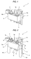
- Fig. 1 is a perspective view of a main part of an embodiment of an electric junction box of the invention
- Fig. 2 is a perspective view showing a state in which an input electric wire and an output electric wire are attached to the electric junction box shown in Fig. 1
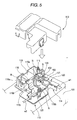
- Fig. 3 is a perspective view of the electric junction box as seen in a direction indicated by an arrow III in Fig. 2
- Fig. 4 is a sectional view taken along the line IV-IV in Fig. 2 and seen in a direction indicated by arrows attached to the line.
- an electric junction box 1 of this embodiment is installed on a vehicle such as a motor vehicle and is made up of a case 2 which is assembled to a vehicle body, an input bus bar 3 and an output bus bar 4, and a fuse 5.
- the case 2 is formed from, for example, an insulating resin material, and a box-shaped fuse mounting portion 10 which is made to open downward is provided on part of a side wall thereof.
- the fuse 5 is inserted into an interior of the fuse mounting portion 10 from below, so as to be accommodated in place within the fuse mounting portion 10.
- the input bus bar 3 and the output bus bar 4 are stamped out from a metallic plate and bent into a predetermined shape and are inserted into bus bar laying out paths 11, 12, respectively, which are provided within the case 2, so as to be accommodated within the case 2.
- the bus bar laying out paths 11, 12 reach the fuse mounting portion 10, and the input bus bar 3 and the output bus bar 4 project into the fuse mounting portion 10 at their distal end portions 3a, 4a.
- various types of electric components accommodated within the case such as relays are connected properly to the input bus bar 3 and the output bus bar 4 so as to form a predetermined circuit.
- the fuse 5 is a so-called flat plate-type fuse, and a flat plate-shaped input terminal 21 is provided on one side edge of a fusible portion 20 which is formed into a substantially rectangular shape as seen from the top thereof, while a flat plate-shaped output terminal 22 is provided on the other side edge of the fusible portion 20 which is paired with the one side edge.
- the fuse 5 is disposed within the fuse mounting portion 10 in such a manner as to cause the fusible portion 20, the input terminal 21 and the output terminal 22 to extend along an inner surface of an upper wall of the fuse mounting portion 10.
- the distal end portion 3a of the input bus bar 3 which projects into the fuse mounting portion 10 is disposed in such a manner as to overlap the input terminal 21 of the fuse 5, and similarly, the distal end portion 4a of the output bus bar 4 which projects into the fuse mounting portion 10 is disposed in such a manner as to overlap the output terminal 22 of the fuse 5.
- the fuse 5 is provided in such a manner as to bridge the distal end portion 3a of the input bus bar 3 and the distal end portion 4a of the output bus bar 4.
- a through hole is pierced in the input terminal 21 of the fuse 5 in such a manner as to penetrate therethrough in a thickness direction, and a through hole is pierced in the distal end portion 3a of the input bus bar 3 in such a manner as to penetrate therethrough in a thickness direction so as to continue to the thorough hole in the input terminal 21 in such a state that the distal end portion 3a overlaps the input terminal 21.
- a through hole 10a is pierced in the upper wall of the fuse mounting portion 10 in such a manner as to penetrate therethrough so as to continue to the through holes provided in the input terminal 21 of the fuse 5 and the distal end portion 3a of the input bus bar 3.
- a through hole is pierced in the output terminal 22 of the fuse 5 in such a manner as to penetrate therethrough in a thickness direction
- a through hole is pierced in the distal end portion 4a of the output bus bar 4 in such a manner as to penetrate therethrough in a thickness direction so as to continue to the thorough hole in the output terminal 22 in such a state that the distal end portion 4a overlaps the output terminal 22.
- a through hole 10b is pierced in the upper wall of the fuse mounting portion 10 in such a manner as to penetrate therethrough so as to continue to the through holes provided in the output terminal 22 of the fuse 5 and the distal end portion 4a of the output bus bar 3.
- the bolts 6, 8 are press fitted in the through holes 10a, 10b or screwed into nuts embedded in the through holes 10a, 10b, respectively, so as to be fixed to the upper wall of the fuse mounting portion 10.
- a proximal end portion of the bolt 6 which projects into the fuse mounting portion 10 is passed through the through holes in the distal end portion 3a of the input side bus bar 3 and the input terminal 21 of the fuse 5, and a nut 7a, which constitutes a constituent element of the input-side fastening member, is screwed on to the proximal end portion of the bolt 6, whereby the distal end portion 3a of the input bus bar 3 and the input terminal 21 of the fuse 5 are fastened to the upper wall of the fuse mounting portion 10 in such a state that the distal end portion 3a and the input terminal 21 overlap each other.
- a proximal end portion of the bolt 8 which projects into the fuse mounting portion 10 is passed through the through holes in the distal end portion 4a of the output side bus bar 4 and the output terminal 22 of the fuse 5, and a nut 9a, which constitutes a constituent element of the input-side fastening member, is screwed on to the proximal end portion of the bolt 8, whereby the distal end portion 4a of the output bus bar 4 and the output terminal 22 of the fuse 5 are fastened to the upper wall of the fuse mounting portion 10 in such a state that the distal end portion 4a and the output terminal 22 overlap each other.
- a through hole 10c is pierced in a portion of the upper wall of the fuse mounting portion 10 which lies right above the fusible portion 20 of the fuse 5, that is, a portion which lies between the through holes 10a, 10b through which the bolts 6, 8 are passed, in such a manner as to penetrate through the upper wall. It is designed that the state of the fusible portion 20 of the fuse 5 (that is, whether or not the fusible portion 20 is fused) can be confirmed through this through hole 10c from the outside.
- an electric wire W1 connected to a battery installed on the vehicle and, for example, an electric wire W2 connected to an alternator installed on the vehicle are attached to the electric junction box after the fabrication thereof.
- Connecting terminals T1, T2 are crimped to terminal ends of the electric wires W1, W2, respectively.
- the terminal end of the electric wire W1 is disposed on the outside of the fuse mounting portion 10 along a side wall of the fuse mounting portion 10 which lies closer to the bolt 6, and the connecting terminal T1 which is crimped to this terminal end is bent substantially at right angles at a distal end thereof which is formed into a flat plate shape, a through hole being pierced in this distal end portion T1a in such a manner as to penetrate therethrough in a thickness direction.
- the distal end portion T1a is placed on the upper wall of the fuse mounting portion 10 while a distal end portion of the bolt 6 which is exposed to the outside from the upper wall of the fuse mounting portion 10 is being passed through the through hole provided in the distal end portion T1a, and a nut 7b, which constitutes a constituent element of the input-side fastening member, is screwed on to the distal end portion of the bolt 6, whereby the connecting terminal T1 is fastened to the upper wall of the fuse mounting portion 10.
- the terminal end of the electric wire W2 is disposed on the outside of the fuse mounting portion 10 along a side wall of the fuse mounting portion 10 which lies closer to the bolt 8, and the connecting terminal T2 which is crimped to this terminal end is bent substantially at right angles at a distal end thereof which is formed into a flat plate shape, a through hole being pierced in this distal end portion T2a in such a manner as to penetrate therethrough in a thickness direction.
- the distal end portion T2a is placed on the upper wall of the fuse mounting portion 10 while a distal end portion of the bolt 8 which is exposed to the outside from the upper wall of the fuse mounting portion 10 is being passed through the through hole provided in the distal end portion T2a, and a nut 9b, which constitutes a constituent element of the input-side fastening member, is screwed on to the distal end portion of the bolt 8, whereby the connecting terminal T2 is fastened to the upper wall of the fuse mounting portion 10.
- the bolt 6 and nuts 7a, 7b and the bolt 8 and the nuts 9a, 9b are made of a metal, for example, and they are all conductive. Then, the input terminal 21 of the fuse 5 and the distal end portion 3a of the input bus bar 3 are made to overlap each other so as to be electrically connected to each other, and the input terminal 21 of the fuse 5 and the distal end portion 3a of the input bus bar 3, and the connecting terminal T1 of the electric wire W1 are electrical connected to each other via the conductive bolt 6 and nuts 7a, 7b.
- the output terminal 22 of the fuse and the distal end portion 4a of the output bus bar 4 are made to overlap each other so as to be electrically connected to each other, and the output terminal 22 of the fuse 5 and the distal end portion 4a of the output bus bar 4, and the connecting terminal T2 of the electric wire W2 are electrically connected to each other via the conductive bolt 8 and nuts 9a, 9b.
- the input terminal 21 of the fuse 5 and the connecting terminal T1 of the input electric wire W1 are electrically connected to the input bus bar 3 by the common input-side fastening members 6, 7a, 7b, and the output terminal 22 of the fuse 5 and the connecting terminal T2 of the output electric wire W2 are electrically connected to the output bus bar 4 by the common output-side fastening members 8, 9a, 9b, whereby not only the number of fastening members can be reduced so as to realize a reduction in the production costs of the electric junction box 1 but also the number of electric components that can be accommodated in the electric junction box 1 can be increased.
- the input-side fastening member 6 which fastens together the input terminal 21 of the fuse 5 and the input bus bar 3 in the overlapping fashion within the case 2 is passed through the case 2, and the connecting terminal T1 of the input electric wire W1 is fastened to the case 2 at the distal end portion of the input-side fastening member 6 which is exposed to the outside of the case 2.
- the output-side fastening member 8 which fastens together the output terminal 22 of the fuse 5 and the output bus bar 4 in the overlapping fashion within the case 2 is passed through the case 2, and the connecting terminal T2 of the output electric wire W2 is fastened to the case 2 at the distal end portion of the output-side fastening member 8 which is exposed to the outside of the case 2.
Landscapes
- Connection Or Junction Boxes (AREA)
- Fuses (AREA)
Abstract
Description
- The present invention relates to an electric junction box which functions to distribute a power supply and protect a circuit.
- An electric junction box is installed on a vehicle such a motor vehicle for distribution of a power supply and protection of a circuit. As a conventional electric junction box, there has been known an electric junction box as shown in Fig. 5 (for example, refer to
JP-A-2004-47189 - As is shown in Fig. 5, an electric junction box disclosed in
JP-A-2004-47189 battery fuse 110 and aninput bus bar 115 and anoutput bus bar 116 which are connected to terminals of thebattery fuse 110 are accommodated in an interior of a case which is made up of alower cover 112, anupper cover 113 and a casemain body 114. - An
input terminal 110b of thebattery fuse 110 is laid to overlap a distal end of theinput bus bar 115 with a threadedportion 115a provided at a distal end portion of theinput bus bar 115 in such a manner as to project therefrom passed through a through hole provided in theinput terminal 110b, so as to be fastened in place with a nut N. Similarly, anoutput terminal 110c of thebattery fuse 110 is laid to overlap a distal end of theoutput bus bar 116 with a threadedportion 116a provided at a distal end portion of theoutput bus bar 116 in such a manner as to project therefrom passed through a through hole provided in theoutput terminal 110c, so as to be fastened in place with a nut N. - Then, a
battery terminal 120 connected under pressure to a distal end of an electric wire W1 of a power supply circuit has a pair offastening pieces battery post 102 which is provided on an upper surface of abattery box 101 in such a manner as to project therefrom, and distal end portions of thesefastening pieces input bus bar 115, so as to be fastened with a bolt and a nut. In addition, aterminal 125 of an electric wire W2 which connects to a relay box is laid to overlap a proximal end portion of theoutput bus bar 116 with a threadedportion 116b provided on the proximal end portion of theoutput bus bar 116 in such a manner as to project therefrom passed through a through hole provided in theterminal 125, so as to be fastened with a nut N. - Note that conventionally, there have been known various types of fuses which are adapted to be fastened to bus bars or the like with bolts and nuts (for example, refer to
JP-A-2001-110297 JP-A-2000-113803 JP-A-11-312454 JP-A-11-213853 JP-A-8-7743 - In the electric junction box disclosed in
JP-A-2004-47189 portion 115a and the nut N which function as a fastening member for electrically connecting theinput terminal 110b of thebattery fuse 110 to theinput bus bar 115, the bolt and the nut N are provided as a fastening member for electrically connecting thebattery terminal 120 of the electric wire W1 of the power supply circuit to theinput bus bar 115. Similarly, in addition to the threadedportion 116a and the nut N which function as a fastening member for electrically connecting theoutput terminal 110c of thebattery fuse 110 to theoutput bus bar 116, the bolt and the nut N are provided as a fastening member for electrically connecting theterminal 125 of the electric wire W2 which connects to the relay box to theoutput bus bar 116. - Thus, in the electric junction box disclosed in
JP-A-2004-47189 input terminal 110b and theoutput terminal 110c of thebattery fuse 110, as well as thebattery terminal 120 of the electric wire W1 and theterminal 125 of the electric wire W2 to theinput bus bar 115 and theoutput bus bar 116, respectively, and the number of manhours necessary to fasten the fastening members is increased, these having constituted a root cause for an increase in the production costs of the electric junction box 111. - In addition, in the electric junction box disclosed in
JP-A-2004-47189 - The invention was made in view of the situations described above, and an object thereof is to provide an electric junction box which can realize a reduction in production costs and an increase in the number of electric components that can be accommodated therein.
- The object is to be achieved by an electric junction box which will be described below under (1).
- (1) An electric junction box including a case, an input bus bar and an output bus bar which are accommodated within the case and a fuse accommodated within the case in such a manner as to bridge the input bus bar and the output bus bar, wherein an input electric wire and an output electric wire are electrically connected to the input bus bar and the output bus bar, respectively, the electric junction box further including an input-side fastening member which fastens an input terminal of the fuse and the input bus bar to the case in such a state that the input terminal is laid to overlap the input bus bar, and an output-side fastening member which fastens an output terminal of the fuse and the output bus bar to the case in such a state that the output terminal is laid to overlap the output bus bar, wherein the input-side fastening member and the output-side fastening member are conductive and are passed through the case, and a connecting terminal of the input electric wire is fastened to the case at a distal end portion of the input-side fastening member which is exposed from the case, and a connecting terminal of the output electric wire is fastened to the case at a distal end portion of the output-side fastening member which is exposed from the case.
- According to the electric junction box which is configured as described under (1) above, the input terminal of the fuse and the connecting terminal of the input electric wire are electrically connected to the input bus bar by the common input-side fastening member, and the output terminal of the fuse and the connecting terminal of the output electric wire are electrically connected to the output bus bar by the common output-side fastening member, whereby not only the number of fastening members can be reduced so as to realize a reduction in the production costs of the electric junction box but also the number of electric components that can be accommodated in the electric junction box can be increased. Furthermore, according to the electric junction box configured according to the invention, the input-side fastening member which fastens together the input terminal of the fuse and the input bus bar in the overlapping fashion within the case is passed through the case, and the connecting terminal of the input electric wire is fastened to the case at the distal end portion of the input-side fastening member which is exposed to the outside of the case. In addition, the output-side fastening member which fastens together the output terminal of the fuse and the output bus bar in the overlapping fashion within the case is passed through the case, and the connecting terminal of the output electric wire is fastened to the case at the distal end portion of the output-side fastening member which is exposed to the outside of the case. By adopting this configuration, when so fastening to the case the connecting terminals of the input electric wire and the output electric wire which are to be attached to the electric junction box after the fabrication thereof, since the fastening of the input terminal of the fuse to the input bus bar and the output terminal of the fuse to the output bus bar does not have to be released and hence, not only a superior workability is provided but also the input terminal of the fuse and the input bus bar, and the output terminal of the fuse and the output bus bar can be kept fastened together strongly and rigidly, thereby making it possible to prevent the dislodgement of the fuse, input bus bar and output bus bar from the case.
- In this way, according to the invention, the production costs of the electric junction box can be reduced, and furthermore, the number of electric components that can be accommodated within the electric junction box can be increased.
-
- Fig. 1 is a perspective of a main part of an embodiment of an electric junction box of the invention.
- Fig. 2 is a perspective view showing a state in which an input electric wire and an output electric wire are attached to the electric junction box shown in Fig. 1.
- Fig. 3 is a perspective view of the electric junction box as seen in a direction indicated by an arrow III in Fig. 2.
- Fig. 4 is a sectional view taken along the line IV-IV in Fig. 2 and seen in a direction indicated by arrows attached to the line.
- Fig. 5 is an exploded perspective view of a conventional electric junction box.
- Hereinafter, a preferred embodiment of an electric junction box of the invention will be described in detail based on the drawings.
- Fig. 1 is a perspective view of a main part of an embodiment of an electric junction box of the invention, Fig. 2 is a perspective view showing a state in which an input electric wire and an output electric wire are attached to the electric junction box shown in Fig. 1, Fig. 3 is a perspective view of the electric junction box as seen in a direction indicated by an arrow III in Fig. 2, and Fig. 4 is a sectional view taken along the line IV-IV in Fig. 2 and seen in a direction indicated by arrows attached to the line.
- As is shown in Figs. 1 to 3, an electric junction box 1 of this embodiment is installed on a vehicle such as a motor vehicle and is made up of a
case 2 which is assembled to a vehicle body, aninput bus bar 3 and anoutput bus bar 4, and afuse 5. - The
case 2 is formed from, for example, an insulating resin material, and a box-shapedfuse mounting portion 10 which is made to open downward is provided on part of a side wall thereof. Thefuse 5 is inserted into an interior of thefuse mounting portion 10 from below, so as to be accommodated in place within thefuse mounting portion 10. - The
input bus bar 3 and theoutput bus bar 4 are stamped out from a metallic plate and bent into a predetermined shape and are inserted into bus bar laying outpaths case 2, so as to be accommodated within thecase 2. The bus bar laying outpaths fuse mounting portion 10, and theinput bus bar 3 and theoutput bus bar 4 project into thefuse mounting portion 10 at theirdistal end portions input bus bar 3 and theoutput bus bar 4 so as to form a predetermined circuit. - The
fuse 5 is a so-called flat plate-type fuse, and a flat plate-shaped input terminal 21 is provided on one side edge of afusible portion 20 which is formed into a substantially rectangular shape as seen from the top thereof, while a flat plate-shaped output terminal 22 is provided on the other side edge of thefusible portion 20 which is paired with the one side edge. Thefuse 5 is disposed within thefuse mounting portion 10 in such a manner as to cause thefusible portion 20, theinput terminal 21 and theoutput terminal 22 to extend along an inner surface of an upper wall of thefuse mounting portion 10. - The
distal end portion 3a of theinput bus bar 3 which projects into thefuse mounting portion 10 is disposed in such a manner as to overlap theinput terminal 21 of thefuse 5, and similarly, thedistal end portion 4a of theoutput bus bar 4 which projects into thefuse mounting portion 10 is disposed in such a manner as to overlap theoutput terminal 22 of thefuse 5. Namely, thefuse 5 is provided in such a manner as to bridge thedistal end portion 3a of theinput bus bar 3 and thedistal end portion 4a of theoutput bus bar 4. - A through hole is pierced in the
input terminal 21 of thefuse 5 in such a manner as to penetrate therethrough in a thickness direction, and a through hole is pierced in thedistal end portion 3a of theinput bus bar 3 in such a manner as to penetrate therethrough in a thickness direction so as to continue to the thorough hole in theinput terminal 21 in such a state that thedistal end portion 3a overlaps theinput terminal 21. In addition, athrough hole 10a is pierced in the upper wall of thefuse mounting portion 10 in such a manner as to penetrate therethrough so as to continue to the through holes provided in theinput terminal 21 of thefuse 5 and thedistal end portion 3a of theinput bus bar 3. - Similarly, a through hole is pierced in the
output terminal 22 of thefuse 5 in such a manner as to penetrate therethrough in a thickness direction, and a through hole is pierced in thedistal end portion 4a of theoutput bus bar 4 in such a manner as to penetrate therethrough in a thickness direction so as to continue to the thorough hole in theoutput terminal 22 in such a state that thedistal end portion 4a overlaps theoutput terminal 22. In addition, athrough hole 10b is pierced in the upper wall of thefuse mounting portion 10 in such a manner as to penetrate therethrough so as to continue to the through holes provided in theoutput terminal 22 of thefuse 5 and thedistal end portion 4a of theoutput bus bar 3. - A
bolt 6, which constitutes a constituent element of an input-side fastening member, is passed through the throughhole 10a provided in the upper wall of thefuse mounting portion 10, while abolt 8, which constitutes a constituent element of an output-side fastening member, is passed through the throughhole 10b. Thebolts holes holes fuse mounting portion 10. - A proximal end portion of the
bolt 6 which projects into thefuse mounting portion 10 is passed through the through holes in thedistal end portion 3a of the inputside bus bar 3 and theinput terminal 21 of thefuse 5, and anut 7a, which constitutes a constituent element of the input-side fastening member, is screwed on to the proximal end portion of thebolt 6, whereby thedistal end portion 3a of theinput bus bar 3 and theinput terminal 21 of thefuse 5 are fastened to the upper wall of thefuse mounting portion 10 in such a state that thedistal end portion 3a and theinput terminal 21 overlap each other. - Similarly, a proximal end portion of the
bolt 8 which projects into thefuse mounting portion 10 is passed through the through holes in thedistal end portion 4a of the outputside bus bar 4 and theoutput terminal 22 of thefuse 5, and anut 9a, which constitutes a constituent element of the input-side fastening member, is screwed on to the proximal end portion of thebolt 8, whereby thedistal end portion 4a of theoutput bus bar 4 and theoutput terminal 22 of thefuse 5 are fastened to the upper wall of thefuse mounting portion 10 in such a state that thedistal end portion 4a and theoutput terminal 22 overlap each other. - Here, a
through hole 10c is pierced in a portion of the upper wall of thefuse mounting portion 10 which lies right above thefusible portion 20 of thefuse 5, that is, a portion which lies between the throughholes bolts fusible portion 20 of the fuse 5 (that is, whether or not thefusible portion 20 is fused) can be confirmed through this throughhole 10c from the outside. - In addition, for example, an electric wire W1 connected to a battery installed on the vehicle and, for example, an electric wire W2 connected to an alternator installed on the vehicle are attached to the electric junction box after the fabrication thereof. Connecting terminals T1, T2 are crimped to terminal ends of the electric wires W1, W2, respectively.
- The terminal end of the electric wire W1 is disposed on the outside of the
fuse mounting portion 10 along a side wall of thefuse mounting portion 10 which lies closer to thebolt 6, and the connecting terminal T1 which is crimped to this terminal end is bent substantially at right angles at a distal end thereof which is formed into a flat plate shape, a through hole being pierced in this distal end portion T1a in such a manner as to penetrate therethrough in a thickness direction. Then, the distal end portion T1a is placed on the upper wall of thefuse mounting portion 10 while a distal end portion of thebolt 6 which is exposed to the outside from the upper wall of thefuse mounting portion 10 is being passed through the through hole provided in the distal end portion T1a, and anut 7b, which constitutes a constituent element of the input-side fastening member, is screwed on to the distal end portion of thebolt 6, whereby the connecting terminal T1 is fastened to the upper wall of thefuse mounting portion 10. - Similarly, the terminal end of the electric wire W2 is disposed on the outside of the
fuse mounting portion 10 along a side wall of thefuse mounting portion 10 which lies closer to thebolt 8, and the connecting terminal T2 which is crimped to this terminal end is bent substantially at right angles at a distal end thereof which is formed into a flat plate shape, a through hole being pierced in this distal end portion T2a in such a manner as to penetrate therethrough in a thickness direction. Then, the distal end portion T2a is placed on the upper wall of thefuse mounting portion 10 while a distal end portion of thebolt 8 which is exposed to the outside from the upper wall of thefuse mounting portion 10 is being passed through the through hole provided in the distal end portion T2a, and anut 9b, which constitutes a constituent element of the input-side fastening member, is screwed on to the distal end portion of thebolt 8, whereby the connecting terminal T2 is fastened to the upper wall of thefuse mounting portion 10. - The
bolt 6 andnuts bolt 8 and thenuts input terminal 21 of thefuse 5 and thedistal end portion 3a of theinput bus bar 3 are made to overlap each other so as to be electrically connected to each other, and theinput terminal 21 of thefuse 5 and thedistal end portion 3a of theinput bus bar 3, and the connecting terminal T1 of the electric wire W1 are electrical connected to each other via theconductive bolt 6 andnuts output terminal 22 of the fuse and thedistal end portion 4a of theoutput bus bar 4 are made to overlap each other so as to be electrically connected to each other, and theoutput terminal 22 of thefuse 5 and thedistal end portion 4a of theoutput bus bar 4, and the connecting terminal T2 of the electric wire W2 are electrically connected to each other via theconductive bolt 8 andnuts - As has been described heretofore, according to the electric junction box 1 of the embodiment, the
input terminal 21 of thefuse 5 and the connecting terminal T1 of the input electric wire W1 are electrically connected to theinput bus bar 3 by the common input-side fastening members output terminal 22 of thefuse 5 and the connecting terminal T2 of the output electric wire W2 are electrically connected to theoutput bus bar 4 by the common output-side fastening members - Furthermore, according to the electric junction box 1 of the embodiment, the input-
side fastening member 6 which fastens together theinput terminal 21 of thefuse 5 and theinput bus bar 3 in the overlapping fashion within thecase 2 is passed through thecase 2, and the connecting terminal T1 of the input electric wire W1 is fastened to thecase 2 at the distal end portion of the input-side fastening member 6 which is exposed to the outside of thecase 2. In addition, the output-side fastening member 8 which fastens together theoutput terminal 22 of thefuse 5 and theoutput bus bar 4 in the overlapping fashion within thecase 2 is passed through thecase 2, and the connecting terminal T2 of the output electric wire W2 is fastened to thecase 2 at the distal end portion of the output-side fastening member 8 which is exposed to the outside of thecase 2. By adopting this configuration, when so fastening to thecase 2 the connecting terminals T1, T2 of the input electric wire W1 and the output electric wire W2 which are to be attached to the electric junction box 1 after the fabrication thereof, since the fastening of theinput terminal 21 of thefuse 5 to theinput bus bar 3 and theoutput terminal 22 of thefuse 5 to theoutput bus bar 4 does not have to be released and hence, not only a superior workability is provided but also theinput terminal 21 of thefuse 5 and theinput bus bar 3, and theoutput terminal 22 of thefuse 5 and theoutput bus bar 4 can be kept fastened together strongly and rigidly, thereby making it possible to prevent the dislodgement of thefuse 5,input bus bar 3 andoutput bus bar 4 from thecase 2. - Note that the invention is not limited to the embodiment that has been described heretofore and can be modified and improved properly.
Claims (1)
- An electric junction box comprising:a case;an input bus bar and an output bus bar which are accommodated within the case; anda fuse accommodated within the case such as to bridge the input bus bar and the output bus bar, wherein an input electric wire and an output electric wire are electrically connected to the input bus bar and the output bus bar, respectively;an input-side fastening member which fastens an input terminal of the fuse and the input bus bar to the case such that the input terminal is laid to overlap the input bus bar; andan output-side fastening member which fastens an output terminal of the fuse and the output bus bar to the case such that the output terminal is laid to overlap the output bus bar,wherein the input-side fastening member and the output-side fastening member are conductive and are passed through the case, and
a connecting terminal of the input electric wire is fastened to the case at a distal end portion of the input-side fastening member which is exposed from the case, and a connecting terminal of the output electric wire is fastened to the case at a distal end portion of the output-side fastening member which is exposed from the case.
Applications Claiming Priority (1)
| Application Number | Priority Date | Filing Date | Title |
|---|---|---|---|
| JP2005307179A JP4527042B2 (en) | 2005-10-21 | 2005-10-21 | Electrical junction box |
Publications (2)
| Publication Number | Publication Date |
|---|---|
| EP1777724A1 true EP1777724A1 (en) | 2007-04-25 |
| EP1777724B1 EP1777724B1 (en) | 2008-05-21 |
Family
ID=37614683
Family Applications (1)
| Application Number | Title | Priority Date | Filing Date |
|---|---|---|---|
| EP06021844A Active EP1777724B1 (en) | 2005-10-21 | 2006-10-18 | Electric junction box |
Country Status (4)
| Country | Link |
|---|---|
| US (1) | US7347733B2 (en) |
| EP (1) | EP1777724B1 (en) |
| JP (1) | JP4527042B2 (en) |
| DE (1) | DE602006001283D1 (en) |
Cited By (3)
| Publication number | Priority date | Publication date | Assignee | Title |
|---|---|---|---|---|
| EP2131381A1 (en) * | 2008-06-04 | 2009-12-09 | Valeo Etudes Electroniques | Fuse block with reduced dimensions |
| CN103490184A (en) * | 2012-06-08 | 2014-01-01 | 李尔公司 | Electrical junction box connections |
| CN108701979A (en) * | 2016-03-22 | 2018-10-23 | 住友电装株式会社 | Electric connection box |
Families Citing this family (18)
| Publication number | Priority date | Publication date | Assignee | Title |
|---|---|---|---|---|
| US7591653B2 (en) * | 2006-09-08 | 2009-09-22 | Aees, Inc. | Modular power distribution center |
| JP5074744B2 (en) * | 2006-11-15 | 2012-11-14 | 矢崎総業株式会社 | Electrical junction box |
| US7663466B1 (en) * | 2007-09-21 | 2010-02-16 | Yazaki North America, Inc. | Corner-mounted battery fuse |
| JP5249636B2 (en) * | 2008-05-29 | 2013-07-31 | 矢崎総業株式会社 | Direct battery fuse |
| JP5157765B2 (en) * | 2008-09-03 | 2013-03-06 | 住友電装株式会社 | Electrical junction box |
| US8269596B2 (en) * | 2009-12-23 | 2012-09-18 | Cooper Technologies Company | Universal dual stud modular fuse holder assembly for bussed and non-bussed power connections |
| JP5836811B2 (en) * | 2012-01-13 | 2015-12-24 | 矢崎総業株式会社 | Screw tightening block connection structure |
| JP6026243B2 (en) * | 2012-11-22 | 2016-11-16 | 矢崎総業株式会社 | Electrical junction box |
| DE102013212233A1 (en) * | 2013-06-26 | 2014-12-31 | Zf Friedrichshafen Ag | Device for the mechanical and electrical connection of cable cores of a cable with cable connections of an electrical assembly |
| USD734269S1 (en) | 2013-11-21 | 2015-07-14 | Thomas & Betts International, Llc | Double junction |
| US9947497B2 (en) * | 2014-09-30 | 2018-04-17 | Johnson Controls Technology Company | Integrated connector having sense and switching conductors for a relay used in a battery module |
| US10211610B2 (en) * | 2014-11-13 | 2019-02-19 | Solarcity Corporation | Systems for backfeeding photovoltaic arrays through main breaker boxes |
| US9543104B2 (en) * | 2015-04-17 | 2017-01-10 | Hamilton Sundstrand Corporation | Fuse assemblies |
| DE102015209279A1 (en) * | 2015-05-21 | 2016-11-24 | Robert Bosch Gmbh | Electrical contact arrangement |
| DE202015106368U1 (en) * | 2015-11-23 | 2017-02-24 | Phoenix Contatct GmbH & Co. KG | Distribution system with an electronic fuse terminal and at least a first terminal block |
| JP6569121B2 (en) * | 2016-10-13 | 2019-09-04 | 住友電装株式会社 | Electrical junction box |
| US10283917B1 (en) * | 2017-10-23 | 2019-05-07 | Lear Corporation | Electrical unit |
| US20190123522A1 (en) * | 2017-10-23 | 2019-04-25 | Lear Corporation | Electrical unit |
Citations (5)
| Publication number | Priority date | Publication date | Assignee | Title |
|---|---|---|---|---|
| US5088940A (en) * | 1989-10-24 | 1992-02-18 | Yazaki Corporation | Electrical junction device |
| JPH10247450A (en) * | 1997-03-05 | 1998-09-14 | Yazaki Corp | Wire connection structure to fusible link and wire connection method |
| EP1103998A2 (en) * | 1999-11-25 | 2001-05-30 | Yazaki Corporation | Connecting structure of a fuse link and external terminals |
| US6333846B1 (en) * | 1999-04-27 | 2001-12-25 | Yazaki Corporation | Power supply shut-off apparatus |
| EP1646063A2 (en) * | 2004-10-06 | 2006-04-12 | Yazaki Corporation | Fuse block |
Family Cites Families (13)
| Publication number | Priority date | Publication date | Assignee | Title |
|---|---|---|---|---|
| JPH087743A (en) | 1994-06-15 | 1996-01-12 | Yazaki Corp | Fusible link and assembling method thereof |
| JPH0950836A (en) * | 1995-08-07 | 1997-02-18 | Fujikura Ltd | Fuse connection structure |
| US5645448A (en) * | 1995-10-16 | 1997-07-08 | Yazaki Corporation | Battery connecting module with fuse mounting |
| JPH10255642A (en) * | 1997-03-11 | 1998-09-25 | Yazaki Corp | Fuse holder |
| JP3719475B2 (en) | 1998-01-20 | 2005-11-24 | 矢崎総業株式会社 | High current fuse |
| JPH11312454A (en) | 1998-04-28 | 1999-11-09 | Yazaki Corp | High current fuse for automobile |
| JP2000113803A (en) | 1998-10-01 | 2000-04-21 | Yazaki Corp | High current fuse for automobile |
| JP2001110297A (en) | 1999-10-05 | 2001-04-20 | Yazaki Corp | High current fuse |
| EP1531521B1 (en) * | 2000-03-07 | 2008-04-30 | Sumitomo Wiring Systems, Ltd. | A construction for preventing erroneous assembling of battery terminals, a battery and a set of terminals |
| US6517390B2 (en) * | 2001-01-12 | 2003-02-11 | Hwan-Chang Kim | Connecting terminal for storage battery |
| JP2003125517A (en) * | 2001-10-11 | 2003-04-25 | Sumitomo Wiring Syst Ltd | Electrical junction box with fusible link heat radiating structure |
| JP4023238B2 (en) | 2002-07-09 | 2007-12-19 | 住友電装株式会社 | Fuse box |
| JP4023237B2 (en) * | 2002-07-09 | 2007-12-19 | 住友電装株式会社 | Fuse box fixing structure |
-
2005
- 2005-10-21 JP JP2005307179A patent/JP4527042B2/en not_active Expired - Fee Related
-
2006
- 2006-10-18 DE DE602006001283T patent/DE602006001283D1/en active Active
- 2006-10-18 EP EP06021844A patent/EP1777724B1/en active Active
- 2006-10-19 US US11/582,961 patent/US7347733B2/en active Active
Patent Citations (5)
| Publication number | Priority date | Publication date | Assignee | Title |
|---|---|---|---|---|
| US5088940A (en) * | 1989-10-24 | 1992-02-18 | Yazaki Corporation | Electrical junction device |
| JPH10247450A (en) * | 1997-03-05 | 1998-09-14 | Yazaki Corp | Wire connection structure to fusible link and wire connection method |
| US6333846B1 (en) * | 1999-04-27 | 2001-12-25 | Yazaki Corporation | Power supply shut-off apparatus |
| EP1103998A2 (en) * | 1999-11-25 | 2001-05-30 | Yazaki Corporation | Connecting structure of a fuse link and external terminals |
| EP1646063A2 (en) * | 2004-10-06 | 2006-04-12 | Yazaki Corporation | Fuse block |
Cited By (6)
| Publication number | Priority date | Publication date | Assignee | Title |
|---|---|---|---|---|
| EP2131381A1 (en) * | 2008-06-04 | 2009-12-09 | Valeo Etudes Electroniques | Fuse block with reduced dimensions |
| FR2932312A1 (en) * | 2008-06-04 | 2009-12-11 | Valeo Etudes Electroniques | FUSE HOUSING WITH LOW DIMENSIONS |
| CN103490184A (en) * | 2012-06-08 | 2014-01-01 | 李尔公司 | Electrical junction box connections |
| CN103490184B (en) * | 2012-06-08 | 2016-05-18 | 李尔公司 | Electrical connection box assembly connects |
| CN108701979A (en) * | 2016-03-22 | 2018-10-23 | 住友电装株式会社 | Electric connection box |
| CN108701979B (en) * | 2016-03-22 | 2020-10-16 | 住友电装株式会社 | Electrical connection box |
Also Published As
| Publication number | Publication date |
|---|---|
| EP1777724B1 (en) | 2008-05-21 |
| US20070091547A1 (en) | 2007-04-26 |
| US7347733B2 (en) | 2008-03-25 |
| JP4527042B2 (en) | 2010-08-18 |
| DE602006001283D1 (en) | 2008-07-03 |
| JP2007115580A (en) | 2007-05-10 |
Similar Documents
| Publication | Publication Date | Title |
|---|---|---|
| EP1777724B1 (en) | Electric junction box | |
| US7592892B2 (en) | Fusible link unit accommodated in in-vehicle electrical connection box | |
| US8721367B2 (en) | Fuse unit | |
| KR101461300B1 (en) | Fuse unit | |
| US6325640B1 (en) | Electrical junction box having a bus bar | |
| US10269524B2 (en) | Multiple fuse device | |
| EP2124239A1 (en) | Multiple fuse device for vehicle | |
| JP4211589B2 (en) | Fusible link and battery fuse unit containing fusible link | |
| JP2005190735A (en) | Fusible link unit | |
| JP6183701B2 (en) | Directly attached battery fusible link | |
| US20130120101A1 (en) | Fuse block device | |
| JP5147614B2 (en) | Battery terminal mounting fuse unit | |
| JP5441260B2 (en) | Fusible link unit | |
| JP7568518B2 (en) | Fuse Unit | |
| JP2005168178A (en) | Electrical junction box | |
| JP4687552B2 (en) | Integrated fuse | |
| KR102755709B1 (en) | Multi-link fuse, and method for manufacturing the multi-link fuse | |
| JP3498658B2 (en) | Fuse box unit | |
| JP6424065B2 (en) | Switch box | |
| JP2011258487A (en) | Battery cover | |
| JP2020126766A (en) | Clip connection structure, electrical connection box, and wire harness | |
| JP5531565B2 (en) | Electrical junction box and method of manufacturing electrical junction box | |
| JP2024027390A (en) | Fuse unit and fuse unit assembly method | |
| JP2022080937A (en) | Terminal part insulation structure and electric connection box | |
| JP4177247B2 (en) | Busbar fuse connection structure and electrical connection box including the same |
Legal Events
| Date | Code | Title | Description |
|---|---|---|---|
| PUAI | Public reference made under article 153(3) epc to a published international application that has entered the european phase |
Free format text: ORIGINAL CODE: 0009012 |
|
| AK | Designated contracting states |
Kind code of ref document: A1 Designated state(s): AT BE BG CH CY CZ DE DK EE ES FI FR GB GR HU IE IS IT LI LT LU LV MC NL PL PT RO SE SI SK TR |
|
| AX | Request for extension of the european patent |
Extension state: AL BA HR MK YU |
|
| RAP1 | Party data changed (applicant data changed or rights of an application transferred) |
Owner name: YAZAKI CORPORATION |
|
| 17P | Request for examination filed |
Effective date: 20070803 |
|
| GRAP | Despatch of communication of intention to grant a patent |
Free format text: ORIGINAL CODE: EPIDOSNIGR1 |
|
| RIN1 | Information on inventor provided before grant (corrected) |
Inventor name: MURAKAMI, TOMOYASU |
|
| AKX | Designation fees paid |
Designated state(s): DE FR GB |
|
| GRAS | Grant fee paid |
Free format text: ORIGINAL CODE: EPIDOSNIGR3 |
|
| GRAA | (expected) grant |
Free format text: ORIGINAL CODE: 0009210 |
|
| AK | Designated contracting states |
Kind code of ref document: B1 Designated state(s): DE FR GB |
|
| REG | Reference to a national code |
Ref country code: GB Ref legal event code: FG4D |
|
| REF | Corresponds to: |
Ref document number: 602006001283 Country of ref document: DE Date of ref document: 20080703 Kind code of ref document: P |
|
| PLBE | No opposition filed within time limit |
Free format text: ORIGINAL CODE: 0009261 |
|
| STAA | Information on the status of an ep patent application or granted ep patent |
Free format text: STATUS: NO OPPOSITION FILED WITHIN TIME LIMIT |
|
| 26N | No opposition filed |
Effective date: 20090224 |
|
| REG | Reference to a national code |
Ref country code: FR Ref legal event code: PLFP Year of fee payment: 11 |
|
| REG | Reference to a national code |
Ref country code: FR Ref legal event code: PLFP Year of fee payment: 12 |
|
| REG | Reference to a national code |
Ref country code: FR Ref legal event code: PLFP Year of fee payment: 13 |
|
| PGFP | Annual fee paid to national office [announced via postgrant information from national office to epo] |
Ref country code: GB Payment date: 20250828 Year of fee payment: 20 |
|
| PGFP | Annual fee paid to national office [announced via postgrant information from national office to epo] |
Ref country code: FR Payment date: 20250908 Year of fee payment: 20 |
|
| PGFP | Annual fee paid to national office [announced via postgrant information from national office to epo] |
Ref country code: DE Payment date: 20250902 Year of fee payment: 20 |