EP1777514A1 - Method and apparatus for non-destructive testing of components of gas turbine engines made of monocrystalline materials - Google Patents
Method and apparatus for non-destructive testing of components of gas turbine engines made of monocrystalline materials Download PDFInfo
- Publication number
- EP1777514A1 EP1777514A1 EP05109851A EP05109851A EP1777514A1 EP 1777514 A1 EP1777514 A1 EP 1777514A1 EP 05109851 A EP05109851 A EP 05109851A EP 05109851 A EP05109851 A EP 05109851A EP 1777514 A1 EP1777514 A1 EP 1777514A1
- Authority
- EP
- European Patent Office
- Prior art keywords
- ultrasonic waves
- component
- components
- positioning
- area
- Prior art date
- Legal status (The legal status is an assumption and is not a legal conclusion. Google has not performed a legal analysis and makes no representation as to the accuracy of the status listed.)
- Granted
Links
Images


Classifications
-
- G—PHYSICS
- G01—MEASURING; TESTING
- G01N—INVESTIGATING OR ANALYSING MATERIALS BY DETERMINING THEIR CHEMICAL OR PHYSICAL PROPERTIES
- G01N29/00—Investigating or analysing materials by the use of ultrasonic, sonic or infrasonic waves; Visualisation of the interior of objects by transmitting ultrasonic or sonic waves through the object
- G01N29/22—Details, e.g. general constructional or apparatus details
- G01N29/28—Details, e.g. general constructional or apparatus details providing acoustic coupling, e.g. water
-
- G—PHYSICS
- G01—MEASURING; TESTING
- G01N—INVESTIGATING OR ANALYSING MATERIALS BY DETERMINING THEIR CHEMICAL OR PHYSICAL PROPERTIES
- G01N29/00—Investigating or analysing materials by the use of ultrasonic, sonic or infrasonic waves; Visualisation of the interior of objects by transmitting ultrasonic or sonic waves through the object
- G01N29/04—Analysing solids
- G01N29/043—Analysing solids in the interior, e.g. by shear waves
-
- G—PHYSICS
- G01—MEASURING; TESTING
- G01N—INVESTIGATING OR ANALYSING MATERIALS BY DETERMINING THEIR CHEMICAL OR PHYSICAL PROPERTIES
- G01N29/00—Investigating or analysing materials by the use of ultrasonic, sonic or infrasonic waves; Visualisation of the interior of objects by transmitting ultrasonic or sonic waves through the object
- G01N29/22—Details, e.g. general constructional or apparatus details
- G01N29/225—Supports, positioning or alignment in moving situation
-
- G—PHYSICS
- G01—MEASURING; TESTING
- G01N—INVESTIGATING OR ANALYSING MATERIALS BY DETERMINING THEIR CHEMICAL OR PHYSICAL PROPERTIES
- G01N2291/00—Indexing codes associated with group G01N29/00
- G01N2291/04—Wave modes and trajectories
- G01N2291/042—Wave modes
- G01N2291/0421—Longitudinal waves
-
- G—PHYSICS
- G01—MEASURING; TESTING
- G01N—INVESTIGATING OR ANALYSING MATERIALS BY DETERMINING THEIR CHEMICAL OR PHYSICAL PROPERTIES
- G01N2291/00—Indexing codes associated with group G01N29/00
- G01N2291/04—Wave modes and trajectories
- G01N2291/042—Wave modes
- G01N2291/0422—Shear waves, transverse waves, horizontally polarised waves
-
- G—PHYSICS
- G01—MEASURING; TESTING
- G01N—INVESTIGATING OR ANALYSING MATERIALS BY DETERMINING THEIR CHEMICAL OR PHYSICAL PROPERTIES
- G01N2291/00—Indexing codes associated with group G01N29/00
- G01N2291/04—Wave modes and trajectories
- G01N2291/044—Internal reflections (echoes), e.g. on walls or defects
-
- G—PHYSICS
- G01—MEASURING; TESTING
- G01N—INVESTIGATING OR ANALYSING MATERIALS BY DETERMINING THEIR CHEMICAL OR PHYSICAL PROPERTIES
- G01N2291/00—Indexing codes associated with group G01N29/00
- G01N2291/26—Scanned objects
- G01N2291/269—Various geometry objects
- G01N2291/2693—Rotor or turbine parts
-
- G—PHYSICS
- G01—MEASURING; TESTING
- G01N—INVESTIGATING OR ANALYSING MATERIALS BY DETERMINING THEIR CHEMICAL OR PHYSICAL PROPERTIES
- G01N2291/00—Indexing codes associated with group G01N29/00
- G01N2291/26—Scanned objects
- G01N2291/269—Various geometry objects
- G01N2291/2694—Wings or other aircraft parts
Definitions
- This invention relates to a method for non-destructive testing of components of gas turbine engines made of monocrystalline materials for the presence of cracks in a certain, critical component area upon expiry of a specific operating time, in particular for the inspection of turbine blades. Moreover, this invention relates to an apparatus for the performance of said method.
- Non-destructive material testing using ultrasound for the detection of shrinkage, cracks and other flaws in the inner of a component has been known for quite a long time.
- the ultrasonic waves produced by the quartz oscillator of an ultrasonic probe positioned on the workpiece surface are transmitted into the component via a couplant. While - on a flawless component - the ultrasonic waves are reflected at the opposite bottom surface, return to the quartz oscillator now acting as receiver and produce a bottom echo, reflection at a discontinuity in the component results in a flaw signal which differs from the bottom echo.
- the shape of the flaw echo displayed on a screen enables the size, depth and type of the defect to be determined by comparing it with the bottom echo.
- the present invention in a broad aspect, provides an inspection method and an inspection apparatus for components made of monocrystalline materials, in particular for crack inspection of turbine blades of gas turbine engines, which ensure a meaningful, safe inspection of the components with minimum time investment.
- An essential inventive feature is that the inspection of components made of monocrystalline materials by longitudinal ultrasonic waves is performed within the engine, i.e. in the installed state of the components. It was found that it is possible to obtain reliable, sufficiently intense, disturbance-free reflection signals on monocrystals, despite the different crystal orientation in the respective components.
- precise positioning of the probe transmitting the ultrasonic waves and receiving the reflected signals, an operation which is extremely difficult to be performed within the engine is accomplished under camera-visual control, with the outer contours of the probe conforming exactly to the outer contour of the component in the area in which the inspection is to be performed so that the probe is virtually form-fitted to the respective area of the component and pre-positioned at least roughly.
- the method according to the present invention enables a great variety of components, for example the blades of the high-pressure turbine, to be quickly and safely inspected at short intervals with minimum assembly effort and cost investment.
- Essential feature of the apparatus for the performance of the method according to the present invention is a specially designed positioning probe for the positionally correct emission of the longitudinal ultrasonic waves for the detection of cracks in a certain - critical - area of the components.
- the probe is provided with an outer contour which conforms to the component in the area to be inspected, enabling the probe to be readily form-fitted at a certain position on the component.
- a further quartz oscillator element for provisioning of a reference or positioning signal is arranged at a defined distance to the quartz oscillator element for the generation of the ultrasonic waves for crack detection, this reference signal being reflected at an inner contour present in the component at a defined distance to the critical area.
- a miniature camera is allocated to the positioning probe to provide visual control of probe manipulation, with the miniature camera and the probe being connected to a flexible manipulation element (manipulator) at whose outer end located outside of the engine are arranged a control unit for moving the probe or the miniature camera, respectively, and, in the one case, a signal indicator unit with change-over switch for displaying the reference signal or, if applicable, a generated flaw signal and, in the other case, a screen for monitoring the probe manipulation movements.
- a flexible manipulation element manipulator
- a supply line is attached to the flexible manipulator for the miniature camera to apply couplant to that area of the component at which the ultrasonic waves are transmitted into the monocrystalline material.
- the supply line enters a metering container filled with couplant with a metering piston that can be actuated by a screw spindle.
- the couplant can be metered manually under visual control and applied positionally correct - also for marking defective components.
- Fig. 1 shows, in longitudinal sectional view, the bottom part of a turbine blade 1 with an airfoil 2, a platform 3 and a blade root 4.
- a cooling air duct 5 provided in the blade root 4 leads from a so-called trombone edge 6 (edge of a trombone duct) to the cooling ducts 7 provided in the airfoil 2.
- trombone edge 6 edge of a trombone duct
- a crack-susceptible - critical - area 8 exists on the left-hand side of the trombone edge 6 in which a crack 9 is schematically shown.
- FIG. 2 The partial view of a gas-turbine engine in Fig. 2 shows, at the exit of the combustion chamber 10, the stator vanes 11 followed by the above-mentioned high-pressure turbine blades 1 to be inspected. All turbine blades 1 on the rotor shall be inspected in the installed state within the engine in the above-mentioned crack-susceptible area using the ultrasonic inspection apparatus described in the following.
- the ultrasonic inspection apparatus For installation of the ultrasonic inspection apparatus, one of the several burners (not shown) is removed from the combustion chamber outer casing 12, enabling the measuring elements required for ultrasonic inspection to be fed through the opening 13 so created in the combustion chamber outer casing 12 and through the burner sleeve 14 up to the respective turbine blade 1.
- the rotor disk, to which the turbine blades 1 are attached, can be gradually advanced by means of a driving device (not shown), this enabling the individual turbine blades 1 on the rotor disk to be inspected one after the other without removing the ultrasonic inspection apparatus.
- a first essential element of the ultrasonic inspection apparatus (also refer to Figs 3 to 6) is a borescope, i.e. a miniature camera 16 attached to the forward end of a flexible first manipulator 15 which is moveable by means of a first control unit 17 in four degrees of freedom, this control unit 17 being connected to the rearward end of the manipulator 15, and provides a pictorial representation of the area of the respective turbine blade 1 to be investigated on a screen 18 provided on the first control unit 17.
- a borescope i.e. a miniature camera 16 attached to the forward end of a flexible first manipulator 15 which is moveable by means of a first control unit 17 in four degrees of freedom, this control unit 17 being connected to the rearward end of the manipulator 15, and provides a pictorial representation of the area of the respective turbine blade 1 to be investigated on a screen 18 provided on the first control unit 17.
- a second essential element of the ultrasonic inspection apparatus is a couplant supply line 19 fitted to the first manipulator 15.
- the forward end of the supply line 19 which - like the miniature camera - is moveable by means of the control unit 17 protrudes beyond the free end face of the miniature camera 16, while the rearward end of the supply line 19 issues into a metering container 20 holding the couplant.
- a manually moveable metering piston 21 - here adjustable via a screw spindle by rotation - for finely dosed application of the couplant 22 in the area of inspection on the respective turbine blade 1 is provided.
- a third essential element of the ultrasonic inspection apparatus is a positioning probe 24 fitted to the forward end of the second manipulator 23.
- a second control unit 25 Connected to the rearward end of the second manipulator 23 located outside of the combustion chamber 10 is a second control unit 25 by which the positioning probe 24 can be moved in any desired direction and - via a change-over switch 26 - a signal indicator 27 (crack detector) for representation of the signals received from the positioning probe 24.
- two - first and second - quartz oscillator elements 28 and 29 acting as transmitter and receiver are arranged on the bottom of the positioning probe 24.
- the quartz oscillator elements 28, 29 are designed for the generation of longitudinal ultrasonic waves.
- the positioning probe 24 is designed such that the longitudinal ultrasonic waves for detection of cracks are emitted precisely into that area of the blade root 4 in which cracking is expected and which, therefore, is to be inspected.
- the probe has a side face 24a which fully fits around the leading edge 2a of the airfoil 2 and the pressure side 2b of the airfoil 2 and a bottom face 24b whose surface contour is completely identical with the surface contour of platform 3 of the turbine blade 2.
- the positioning probe 24 can be form-fitted to the airfoil 2 and the platform 3 in a specific position.
- the two quartz oscillator elements 28, 29 are arranged specific to the blade, on the basis of this blade-specific contour.
- the first quartz oscillator element 28 is arranged such that a positioning (or reference) signal effected by a certain blade geometry - here the trombone edge 6 of the trombone duct - is generated by which the correct position of the positioning probe 24 on the turbine blade 2 is recorded.
- the second quartz oscillator element 29 is arranged at a distance to the first quartz oscillator element 28 adjusted to the blade geometry such that the longitudinal ultrasonic waves generated by it precisely cover the area of the blade root 4 in which cracks are likely to occur and which is to be inspected for crack formation.
- the measuring apparatus proper consisting of the positioning probe 24 and the signal indicator 27 connected to this probe via a change-over switch 26, was calibrated prior to the performance of the inspection.
- a temperature measurement is performed after cooling the high-pressure turbine module.
- a temperature sensor (not shown) is fitted to the manipulator 15 with the miniature camera 16 which slightly protrudes beyond the camera.
- the manipulator 15 with the miniature camera 16 and the temperature sensor are fed through the combustion chamber 10 and between two stator vanes to the turbine blades 1 of the first high-pressure turbine stage.
- the temperature sensed there on a platform 3 is shown outside of the engine on a display unit (not shown) connected to the temperature sensor. If necessary, the engine must be cooled down further and the temperature measurement repeated.
- the supply line 19 connected to the container 20 is attached to the flexible first manipulator 15 fitted to the miniature camera 16. Subsequently, the first manipulator 15 so prepared and the second manipulator 23 with the positioning probe 24 fitted to its end are moved to the first high-pressure turbine stage by manually operating the associated control units 17 or 25, respectively, watching the screen 18.
- the tip of the supply line 19 protruding beyond the miniature camera 16 is placed on that part of the surface of the platform 3 of the respective turbine blade 1 on which the positioning probe 24 is later to be positioned to apply couplant 22 to the platform 3 in a locally and quantitatively controlled manner by operating the metering piston 21 of the metering container 20, and watching the operation with the miniature camera 16.
- the miniature camera 16 is then retracted slightly and the positioning probe 24 positioned on the leading edge 2a and the pressure side 2b of the airfoil 2 with its contoured side face 24a and on the platform 3 with its contoured bottom face 24b.
- the correct position of the positioning probe 24 is only reached if, in the switch position "T" of the change-over switch 26, a reference signal (positioning signal S P ) reflected by the trombone edge 6 of the trombone duct (trombone) is received by the first quartz oscillator element 28 and shown on the display 30 of the signal indicator unit 27 (crack detector).
- the positioning signal S P is shown in a certain zone of the graph in Fig. 7a.
- the longitudinal ultrasonic waves generated by the second quartz oscillator element 29 now cover precisely the area of the blade root 4 in which cracks are likely to occur. If such a crack 9 exists, the longitudinal ultrasonic waves reflected by it will be received by the quartz oscillator element 29 and, after switching the change-over switch 26 to switch position "N", shown on the display 30 as flaw signal S F . In the zone of the graph shown in Fig. 7c in which the positioning signal S P appeared before in switch position "T", a flaw signal S F will now be visible indicating a crack 9 in the blade root 4 of the turbine blade 1 under inspection. In this case, the free end of the supply line 19 attached to the first manipulator 15 is again moved close to the turbine blade 1 and the concave side (pressure side 2b) of the turbine blade 1 marked with couplant.
Landscapes
- Physics & Mathematics (AREA)
- Health & Medical Sciences (AREA)
- Life Sciences & Earth Sciences (AREA)
- Chemical & Material Sciences (AREA)
- Analytical Chemistry (AREA)
- Biochemistry (AREA)
- General Health & Medical Sciences (AREA)
- General Physics & Mathematics (AREA)
- Immunology (AREA)
- Pathology (AREA)
- Acoustics & Sound (AREA)
- Investigating Or Analyzing Materials By The Use Of Ultrasonic Waves (AREA)
Abstract
Description
- This invention relates to a method for non-destructive testing of components of gas turbine engines made of monocrystalline materials for the presence of cracks in a certain, critical component area upon expiry of a specific operating time, in particular for the inspection of turbine blades. Moreover, this invention relates to an apparatus for the performance of said method.
- Non-destructive material testing using ultrasound for the detection of shrinkage, cracks and other flaws in the inner of a component has been known for quite a long time. The ultrasonic waves produced by the quartz oscillator of an ultrasonic probe positioned on the workpiece surface are transmitted into the component via a couplant. While - on a flawless component - the ultrasonic waves are reflected at the opposite bottom surface, return to the quartz oscillator now acting as receiver and produce a bottom echo, reflection at a discontinuity in the component results in a flaw signal which differs from the bottom echo. The shape of the flaw echo displayed on a screen enables the size, depth and type of the defect to be determined by comparing it with the bottom echo.
- Inspection of components made of monocrystalline materials is, however, problematic since transverse ultrasonic waves are reflected differently on monocrystals, depending on the respective crystallographic orientation, as a result of which the signal reflected by a crack actually present in the component will not be reliably received and the discontinuity not safely detected.
- In addition, ultrasonic inspection of monocrystalline components is difficult if the particular geometry of a component area to be flaw-tested leads to disturbance signals, as a result of which the reliability of the inspection is not ensured. Flaw detection is particularly problematic and costly if the components to be inspected are installed in a fixture and have to be removed for non-destructive testing and re-installed afterwards.
- It is known of the blades of gas turbine engines, for example, that they may develop cracks in a certain area of the blade root. At certain intervals, it is therefore advisable to crack-inspect all turbine blades in question in a test laboratory by non-destructive methods. Apart from the high disassembly and assembly effort, the known methods and apparatuses are not capable of detecting, or excluding, crack formation in the inner of the blades in certain critical areas in a quick, safe and simple way. The sensitivity of X-rays used for this purpose is not sufficient to detect cracks in the inner of the turbine blades. Fluorescent inspection, as another well-known inspection method is, however, only suitable for the detection of superficial cracks.
- The present invention, in a broad aspect, provides an inspection method and an inspection apparatus for components made of monocrystalline materials, in particular for crack inspection of turbine blades of gas turbine engines, which ensure a meaningful, safe inspection of the components with minimum time investment.
- It is a particular object of the present invention to provide solution to the above problematics by a method in accordance with the features of
Claim 1 and by an inspection apparatus designed in accordance with the features of Claim 7. Further features and advantageous embodiments of the present invention become apparent from the sub-claims. - An essential inventive feature is that the inspection of components made of monocrystalline materials by longitudinal ultrasonic waves is performed within the engine, i.e. in the installed state of the components. It was found that it is possible to obtain reliable, sufficiently intense, disturbance-free reflection signals on monocrystals, despite the different crystal orientation in the respective components. In accordance with another important feature of the present invention, precise positioning of the probe transmitting the ultrasonic waves and receiving the reflected signals, an operation which is extremely difficult to be performed within the engine, is accomplished under camera-visual control, with the outer contours of the probe conforming exactly to the outer contour of the component in the area in which the inspection is to be performed so that the probe is virtually form-fitted to the respective area of the component and pre-positioned at least roughly. Since a reliable, disturbance-free reflection signal from a crack (flaw signal) is only obtainable if the longitudinal ultrasonic waves are emitted to the critical inspection area from a specific position and direction, additional ultrasonic waves for precise positioning of the probe are emitted at a local distance to the ultrasonic waves for crack detection, i.e. for precise orientation of the latter. These additional ultrasonic waves for fine-positioning of the probe are emitted at a place which corresponds to a contour which, at a defined distance to the critical area, is present within the component. Only a reference signal (for example a trombone signal) reflected by this component-specific contour ensures that the inspection waves are emitted from the correct position into the correct direction and an existing crack is actually detected.
- The method according to the present invention enables a great variety of components, for example the blades of the high-pressure turbine, to be quickly and safely inspected at short intervals with minimum assembly effort and cost investment.
- Essential feature of the apparatus for the performance of the method according to the present invention is a specially designed positioning probe for the positionally correct emission of the longitudinal ultrasonic waves for the detection of cracks in a certain - critical - area of the components. For rough-positioning, the probe is provided with an outer contour which conforms to the component in the area to be inspected, enabling the probe to be readily form-fitted at a certain position on the component. For fine-positioning, a further quartz oscillator element for provisioning of a reference or positioning signal is arranged at a defined distance to the quartz oscillator element for the generation of the ultrasonic waves for crack detection, this reference signal being reflected at an inner contour present in the component at a defined distance to the critical area.
- In accordance with a further important feature of the present invention, a miniature camera is allocated to the positioning probe to provide visual control of probe manipulation, with the miniature camera and the probe being connected to a flexible manipulation element (manipulator) at whose outer end located outside of the engine are arranged a control unit for moving the probe or the miniature camera, respectively, and, in the one case, a signal indicator unit with change-over switch for displaying the reference signal or, if applicable, a generated flaw signal and, in the other case, a screen for monitoring the probe manipulation movements.
- In accordance with another important feature of the present invention, a supply line is attached to the flexible manipulator for the miniature camera to apply couplant to that area of the component at which the ultrasonic waves are transmitted into the monocrystalline material. Outside of the engine, the supply line enters a metering container filled with couplant with a metering piston that can be actuated by a screw spindle. Thus, the couplant can be metered manually under visual control and applied positionally correct - also for marking defective components.
- The present invention is more fully described in the light of the accompanying drawing showing a preferred embodiment. On the drawing,
- Fig. 1
- is a sectional view in the area of the platform and the root of a turbine blade,
- Fig. 2
- is a partial view of the engine and of the inspection apparatus arranged in the area of the combustion chamber and the high-pressure turbine,
- Fig. 3
- is a view of the components of the inspection apparatus that are located outside of the engine,
- Fig. 4
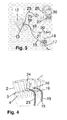
- is an enlarged representation of the inspection apparatus in the area of the turbine blades to be inspected,
- Fig. 5
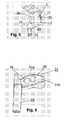
- is a view of a turbine blade with a positioning probe attached to it for the performance of the inspection,
- Fig. 6
- is an underside view of the probe with the two quartz oscillator elements, and
- Figs 7a to c
- show three ultrasonic measuring graphs, in which a) the reference signal, b) no crack signal and c) a crack signal can be recognized.
- Fig. 1 shows, in longitudinal sectional view, the bottom part of a
turbine blade 1 with anairfoil 2, aplatform 3 and ablade root 4. Acooling air duct 5 provided in theblade root 4 leads from a so-called trombone edge 6 (edge of a trombone duct) to the cooling ducts 7 provided in theairfoil 2. In the drawing of Fig. 1, a crack-susceptible - critical -area 8 exists on the left-hand side of thetrombone edge 6 in which acrack 9 is schematically shown. - The partial view of a gas-turbine engine in Fig. 2 shows, at the exit of the
combustion chamber 10, thestator vanes 11 followed by the above-mentioned high-pressure turbine blades 1 to be inspected. Allturbine blades 1 on the rotor shall be inspected in the installed state within the engine in the above-mentioned crack-susceptible area using the ultrasonic inspection apparatus described in the following. For installation of the ultrasonic inspection apparatus, one of the several burners (not shown) is removed from the combustion chamberouter casing 12, enabling the measuring elements required for ultrasonic inspection to be fed through theopening 13 so created in the combustion chamberouter casing 12 and through theburner sleeve 14 up to therespective turbine blade 1. The rotor disk, to which theturbine blades 1 are attached, can be gradually advanced by means of a driving device (not shown), this enabling theindividual turbine blades 1 on the rotor disk to be inspected one after the other without removing the ultrasonic inspection apparatus. - A first essential element of the ultrasonic inspection apparatus (also refer to Figs 3 to 6) is a borescope, i.e. a
miniature camera 16 attached to the forward end of a flexiblefirst manipulator 15 which is moveable by means of afirst control unit 17 in four degrees of freedom, thiscontrol unit 17 being connected to the rearward end of themanipulator 15, and provides a pictorial representation of the area of therespective turbine blade 1 to be investigated on ascreen 18 provided on thefirst control unit 17. - A second essential element of the ultrasonic inspection apparatus is a
couplant supply line 19 fitted to thefirst manipulator 15. The forward end of thesupply line 19 which - like the miniature camera - is moveable by means of thecontrol unit 17 protrudes beyond the free end face of theminiature camera 16, while the rearward end of thesupply line 19 issues into ametering container 20 holding the couplant. In themetering container 20, a manually moveable metering piston 21 - here adjustable via a screw spindle by rotation - for finely dosed application of thecouplant 22 in the area of inspection on therespective turbine blade 1 is provided. - A third essential element of the ultrasonic inspection apparatus is a
positioning probe 24 fitted to the forward end of thesecond manipulator 23. Connected to the rearward end of thesecond manipulator 23 located outside of thecombustion chamber 10 is asecond control unit 25 by which thepositioning probe 24 can be moved in any desired direction and - via a change-over switch 26 - a signal indicator 27 (crack detector) for representation of the signals received from thepositioning probe 24. - As shown in Fig. 6, two - first and second -
quartz oscillator elements positioning probe 24. Thequartz oscillator elements positioning probe 24 is designed such that the longitudinal ultrasonic waves for detection of cracks are emitted precisely into that area of theblade root 4 in which cracking is expected and which, therefore, is to be inspected. The probe has aside face 24a which fully fits around the leadingedge 2a of theairfoil 2 and thepressure side 2b of theairfoil 2 and abottom face 24b whose surface contour is completely identical with the surface contour ofplatform 3 of theturbine blade 2. Thus, thepositioning probe 24 can be form-fitted to theairfoil 2 and theplatform 3 in a specific position. Also, the twoquartz oscillator elements quartz oscillator element 28 is arranged such that a positioning (or reference) signal effected by a certain blade geometry - here thetrombone edge 6 of the trombone duct - is generated by which the correct position of thepositioning probe 24 on theturbine blade 2 is recorded. The secondquartz oscillator element 29 is arranged at a distance to the firstquartz oscillator element 28 adjusted to the blade geometry such that the longitudinal ultrasonic waves generated by it precisely cover the area of theblade root 4 in which cracks are likely to occur and which is to be inspected for crack formation. - In the following, a typical ultrasonic inspection of the turbine blades installed in a gas turbine engine using the above apparatus is described. The measuring apparatus proper, consisting of the
positioning probe 24 and thesignal indicator 27 connected to this probe via a change-over switch 26, was calibrated prior to the performance of the inspection. - In preparation of the inspection, access to the fuel nozzles is first gained on the engine casing and then, upon removal of one fuel nozzle, to the
turbine blades 1 via thecombustion chamber 10. In addition, a rotating device (not shown) is fitted to the engine, enabling the rotor disk with theturbine blades 1 arranged on its circumference to be advanced and one turbine blade after the other to be inspected. - For performance of the ultrasonic inspection, it must also be ensured that the temperature in the area of the high-pressure turbine does not exceed 50°C. Therefore, a temperature measurement is performed after cooling the high-pressure turbine module. For this purpose, a temperature sensor (not shown) is fitted to the
manipulator 15 with theminiature camera 16 which slightly protrudes beyond the camera. - Watching the pictorial representation on the
screen 18, themanipulator 15 with theminiature camera 16 and the temperature sensor are fed through thecombustion chamber 10 and between two stator vanes to theturbine blades 1 of the first high-pressure turbine stage. The temperature sensed there on aplatform 3 is shown outside of the engine on a display unit (not shown) connected to the temperature sensor. If necessary, the engine must be cooled down further and the temperature measurement repeated. - For the inspection, the
supply line 19 connected to thecontainer 20 is attached to the flexiblefirst manipulator 15 fitted to theminiature camera 16. Subsequently, thefirst manipulator 15 so prepared and thesecond manipulator 23 with thepositioning probe 24 fitted to its end are moved to the first high-pressure turbine stage by manually operating the associatedcontrol units screen 18. The tip of thesupply line 19 protruding beyond theminiature camera 16 is placed on that part of the surface of theplatform 3 of therespective turbine blade 1 on which thepositioning probe 24 is later to be positioned to applycouplant 22 to theplatform 3 in a locally and quantitatively controlled manner by operating themetering piston 21 of themetering container 20, and watching the operation with theminiature camera 16. Theminiature camera 16 is then retracted slightly and thepositioning probe 24 positioned on theleading edge 2a and thepressure side 2b of theairfoil 2 with itscontoured side face 24a and on theplatform 3 with its contouredbottom face 24b. However, the correct position of thepositioning probe 24 is only reached if, in the switch position "T" of the change-over switch 26, a reference signal (positioning signal SP) reflected by thetrombone edge 6 of the trombone duct (trombone) is received by the firstquartz oscillator element 28 and shown on thedisplay 30 of the signal indicator unit 27 (crack detector). The positioning signal SP is shown in a certain zone of the graph in Fig. 7a. The longitudinal ultrasonic waves generated by the secondquartz oscillator element 29 now cover precisely the area of theblade root 4 in which cracks are likely to occur. If such acrack 9 exists, the longitudinal ultrasonic waves reflected by it will be received by thequartz oscillator element 29 and, after switching the change-over switch 26 to switch position "N", shown on thedisplay 30 as flaw signal SF. In the zone of the graph shown in Fig. 7c in which the positioning signal SP appeared before in switch position "T", a flaw signal SF will now be visible indicating acrack 9 in theblade root 4 of theturbine blade 1 under inspection. In this case, the free end of thesupply line 19 attached to thefirst manipulator 15 is again moved close to theturbine blade 1 and the concave side (pressure side 2b) of theturbine blade 1 marked with couplant. - In the manner described in the above, all
other turbine blades 1 fitted to the circumference of the rotor disk are now inspected for the presence of possible discontinuities in theblade root 4. Upon retraction of themanipulator 23 withpositioning probe 24 and themanipulator 15 withminiature camera 16 andsupply line 17 for the couplant, the rotor disk is advanced by means of the above-mentioned drive unit such that the next turbine blade can be inspected. If aturbine blade 1 is flawless in the respective crack-susceptible area 8, no crack signal will, as shown in Fig. 7b, be displayed in switch position "N" if a positioning signal SP according to Fig. 7a was generated before in switch position "T". -
- 1
- Turbine blade, component
- 2
- Airfoil
- 2a
- Leading edge
- 2b
- Pressure side
- 3
- Platform
- 4
- Blade root
- 5
- Cooling air duct
- 6
- Trombone edge, geometrical contour
- 7
- Cooling duct in 2
- 8
- Crack-susceptible/critical area of 4
- 9
- Crack in 8
- 10
- Combustion chamber
- 11
- Stator vanes
- 12
- Combustion chamber outer casing
- 13
- Opening in 12
- 14
- Burner sleeve in 10
- 15
- Flexible first manipulator
- 16
- Miniature camera
- 17
- First control unit
- 18
- Screen
- 19
- Supply line
- 20
- Metering container
- 21
- Metering piston
- 22
- Couplant
- 23
- Second manipulator
- 24
- Positioning probe
- 24a
- Side face of 24
- 24b
- Bottom face of 24
- 25
- Second control unit
- 26
- Change-over switch
- 27
- Signal indicator unit, crack detector
- 28
- First quartz oscillator element for reference signal
- 29
- Second quartz oscillator element for flaw signal
- 30
- Display of 27
Claims (10)
- Method for non-destructive testing of components of gas turbine engines made of monocrystalline materials for the presence of cracks in a certain, critical component area upon expiry of a specific operating time, in particular for the inspection of turbine blades, characterized in that a reference signal (SP) is generated, in the installed state of the components in the engine, on a component-specific geometrical contour adjacent to the critical area by means of first longitudinal ultrasonic waves for the purpose of fine-positioning and, upon availability of the reference signal, second longitudinal ultrasonic waves are emitted positionally correct at a local distance from the first ultrasonic waves, corresponding to the location of the critical area to cover the critical area and produce a flaw signal (SF) in the event of crack formation, with the first and second ultrasonic waves being rough-positioned before by means of an ultrasonic probe form-fitted to the outer contour of the components under camera-visual control.
- Method in accordance with Claim 1, characterized in that defective components are marked immediately upon detection of discontinuities.
- Method in accordance with Claim 2, characterized in that the couplant used for transmission of the ultrasonic waves into the component is used for marking.
- Method in accordance with Claim 1 or 2, characterized in that access to the components and rough-positioning and marking within the engine are performed under visual control using a miniature camera.
- Method in accordance with Claim 1, characterized in that the ultrasonic inspection is performed at a component temperature below 50°C.
- Method in accordance with Claim 5, characterized in that the temperature of the components is measured in the engine and the components are cooled, if necessary.
- Apparatus for performance of the method according to Claim 1, characterized by a positioning probe (24)- with a contour of its side and/or bottom faces form-fitted to the surface contour of the area (8) of the components (1) to be inspected for rough-positioning of the first and second ultrasonic waves,- and with a first quartz oscillator element (28) arranged relative to a geometrical contour (6) in or on the respective component (1) for generation of longitudinal ultrasonic waves and for reception of a reference signal (SP) reflected by the contour (6) for fine-positioning of the positioning probe (24),- and with a second quartz oscillator element (29) arranged at a certain distance from the first quartz oscillator element (28) for generation of longitudinal ultrasonic waves in the critical area (8) of the respective component to be inspected and for reception of a flaw signal (SF) reflected by a crack (9) existing in the respective area (8), where- the positioning probe (24) is connected to a flexible manipulator (23) whose free end located outside of the engine is connected to a control unit (25) for moving the manipulator (23) and the positioning probe (24) in various directions and to a signal indicator unit (27) with a display (30) and a change-over switch (26) for indication of either the reference signal (SP) or the flaw signal (SF) reflected on a crack (9), and- a miniature camera (16) attached to a further flexible manipulator (15) is allocated to the positioning probe (24), with a control unit (17) for movement control of the manipulator (15) and the miniature camera (16) as well as a screen (18) being attached to the end of the manipulator (15) located outside of the engine, and- the manipulator (15) being connected, along its length, to a supply line (19) for a couplant (22) whose end located outside of the engine is connected to a metering container (20) for the couplant.
- Apparatus in accordance with Claim 7,
characterized in that the metering container (20) is provided with a metering piston (21) which is adjustable by means of a screw spindle. - Apparatus in accordance with Claim 7,
characterized in that the free end of the supply line (19) protrudes beyond the miniature camera (16) to allow the application of the couplant (22) to the component (1) to be watched without restriction. - Apparatus in accordance with Claim 7,
characterized in that a temperature sensor is connected to the manipulator (15) along its length whose free end protrudes beyond the miniature camera (16) and whose end located outside of the engine is connected to a temperature measuring unit.
Priority Applications (3)
| Application Number | Priority Date | Filing Date | Title |
|---|---|---|---|
| DE602005006574T DE602005006574D1 (en) | 2005-10-21 | 2005-10-21 | Method and apparatus for nondestructive testing of gas turbine engine components from single crystal materials |
| EP05109851A EP1777514B1 (en) | 2005-10-21 | 2005-10-21 | Method and apparatus for non-destructive testing of components of gas turbine engines made of monocrystalline materials |
| US11/584,763 US7543500B2 (en) | 2005-10-21 | 2006-10-23 | Method and apparatus for non-destructive testing of components of gas turbine engines made of monocrystalline materials |
Applications Claiming Priority (1)
| Application Number | Priority Date | Filing Date | Title |
|---|---|---|---|
| EP05109851A EP1777514B1 (en) | 2005-10-21 | 2005-10-21 | Method and apparatus for non-destructive testing of components of gas turbine engines made of monocrystalline materials |
Publications (2)
| Publication Number | Publication Date |
|---|---|
| EP1777514A1 true EP1777514A1 (en) | 2007-04-25 |
| EP1777514B1 EP1777514B1 (en) | 2008-05-07 |
Family
ID=36035740
Family Applications (1)
| Application Number | Title | Priority Date | Filing Date |
|---|---|---|---|
| EP05109851A Expired - Lifetime EP1777514B1 (en) | 2005-10-21 | 2005-10-21 | Method and apparatus for non-destructive testing of components of gas turbine engines made of monocrystalline materials |
Country Status (3)
| Country | Link |
|---|---|
| US (1) | US7543500B2 (en) |
| EP (1) | EP1777514B1 (en) |
| DE (1) | DE602005006574D1 (en) |
Families Citing this family (36)
| Publication number | Priority date | Publication date | Assignee | Title |
|---|---|---|---|---|
| EP1835150A1 (en) * | 2006-03-17 | 2007-09-19 | Siemens Aktiengesellschaft | Method for inspecting a turbine plant and device therefor |
| US8169476B2 (en) * | 2006-11-02 | 2012-05-01 | GM Global Technology Operations LLC | In-cylinder imaging system using high-speed imaging device and high intensity light source for capturing images in combustion chamber |
| US7654144B2 (en) * | 2007-12-13 | 2010-02-02 | Korea Electric Power Corporation | Nondestructive testing apparatus for blade root of steam turbine of power plant |
| WO2011159403A1 (en) | 2010-06-16 | 2011-12-22 | Mueller International, Llc | Infrastructure monitoring devices, systems, and methods |
| US9291520B2 (en) | 2011-08-12 | 2016-03-22 | Mueller International, Llc | Fire hydrant leak detector |
| US10281712B2 (en) | 2012-01-31 | 2019-05-07 | Siemens Energy, Inc. | Single-axis inspection scope with bendable knuckle and method for internal inspection of power generation machinery |
| US8922640B2 (en) * | 2012-01-31 | 2014-12-30 | Siemens Energy, Inc. | System and method for automated optical inspection of industrial gas turbines and other power generation machinery with articulated multi-axis inspection scope |
| US9948835B2 (en) | 2012-01-31 | 2018-04-17 | Siemens Energy, Inc. | Single-axis inspection scope with spherical camera and method for internal inspection of power generation machinery |
| US10274718B2 (en) | 2012-01-31 | 2019-04-30 | Siemens Energy, Inc. | Single-axis inspection scope with anti-rotation extension and method for internal inspection of power generation machinery |
| US9057710B2 (en) | 2012-01-31 | 2015-06-16 | Siemens Energy, Inc. | System and method for automated optical inspection of industrial gas turbines and other power generation machinery |
| US9778141B2 (en) | 2012-01-31 | 2017-10-03 | Siemens Energy, Inc. | Video inspection system with deformable, self-supporting deployment tether |
| US9154743B2 (en) * | 2012-01-31 | 2015-10-06 | Siemens Energy, Inc. | System and method for optical inspection of off-line industrial gas turbines and other power generation machinery while in turning gear mode |
| US9116071B2 (en) * | 2012-01-31 | 2015-08-25 | Siemens Energy, Inc. | System and method for visual inspection and 3D white light scanning of off-line industrial gas turbines and other power generation machinery |
| US9709463B2 (en) | 2012-01-31 | 2017-07-18 | Siemens Energy, Inc. | Method and system for surface profile inspection of off-line industrial gas turbines and other power generation machinery |
| US8713999B2 (en) * | 2012-01-31 | 2014-05-06 | Siemens Energy, Inc. | System and method for automated optical inspection of industrial gas turbines and other power generation machinery with multi-axis inspection scope |
| US9534499B2 (en) * | 2012-04-13 | 2017-01-03 | Caterpillar Inc. | Method of extending the service life of used turbocharger compressor wheels |
| SG11201503041SA (en) | 2012-10-26 | 2015-05-28 | Mueller Int Llc | Detecting leaks in a fluid distribution system |
| US9116098B2 (en) * | 2013-02-12 | 2015-08-25 | General Electric Company | Ultrasonic detection method and system |
| US9599537B2 (en) * | 2013-08-21 | 2017-03-21 | Siemens Energy, Inc. | Internal inspection of machinery by stitched surface imaging |
| GB201401111D0 (en) * | 2014-01-23 | 2014-03-12 | Rolls Royce Plc | A method of inspecting the fan track liner of a gas turbine engine |
| US9681107B2 (en) | 2014-05-22 | 2017-06-13 | Siemens Energy, Inc. | Flexible tether position tracking camera inspection system for visual inspection of off line industrial gas turbines and other power generation machinery |
| US9528903B2 (en) | 2014-10-01 | 2016-12-27 | Mueller International, Llc | Piezoelectric vibration sensor for fluid leak detection |
| US10305178B2 (en) | 2016-02-12 | 2019-05-28 | Mueller International, Llc | Nozzle cap multi-band antenna assembly |
| US10283857B2 (en) | 2016-02-12 | 2019-05-07 | Mueller International, Llc | Nozzle cap multi-band antenna assembly |
| US10738616B2 (en) * | 2016-10-11 | 2020-08-11 | General Electric Company | System and method for maintenance of a turbine assembly |
| CN109580785A (en) * | 2017-09-29 | 2019-04-05 | 上海金艺检测技术有限公司 | Scanning tooling and method for turbine blade root defect |
| US10859462B2 (en) | 2018-09-04 | 2020-12-08 | Mueller International, Llc | Hydrant cap leak detector with oriented sensor |
| US11342656B2 (en) | 2018-12-28 | 2022-05-24 | Mueller International, Llc | Nozzle cap encapsulated antenna system |
| US11473993B2 (en) | 2019-05-31 | 2022-10-18 | Mueller International, Llc | Hydrant nozzle cap |
| US11702953B2 (en) * | 2020-02-03 | 2023-07-18 | General Electric Company | Engine inspection and maintenance tool |
| US11542690B2 (en) | 2020-05-14 | 2023-01-03 | Mueller International, Llc | Hydrant nozzle cap adapter |
| CN111678704B (en) * | 2020-05-29 | 2022-01-04 | 中国航发南方工业有限公司 | Turbofan engine overall performance adjusting method |
| GB202112995D0 (en) * | 2021-09-13 | 2021-10-27 | Rolls Royce Plc | System and method for testing of monocrystalline components |
| US12578245B2 (en) | 2022-10-28 | 2026-03-17 | Mueller International, Llc | Self-leveling sensor assembly |
| US20250341496A1 (en) * | 2024-05-06 | 2025-11-06 | Rtx Corporation | Inspecting internal powerplant component using adhered inspection device(s) |
| US20250347662A1 (en) * | 2024-05-13 | 2025-11-13 | Rtx Corporation | Method for inspecting a powerplant component using an inspection scope |
Citations (2)
| Publication number | Priority date | Publication date | Assignee | Title |
|---|---|---|---|---|
| GB2285129A (en) * | 1991-04-19 | 1995-06-28 | Kawasaki Heavy Ind Ltd | Ultrasonic defect testing |
| US5696324A (en) * | 1995-05-11 | 1997-12-09 | Iwatsu Electric Co., Ltd. | Method and apparatus for predicting the life of an object to be measured using longitudinal waves |
Family Cites Families (4)
| Publication number | Priority date | Publication date | Assignee | Title |
|---|---|---|---|---|
| US5275052A (en) * | 1992-03-06 | 1994-01-04 | New York Institute Of Technology | Tenon inspection systems and methods |
| US5942690A (en) * | 1997-11-25 | 1999-08-24 | Shvetsky; Arkady | Apparatus and method for ultrasonic inspection of rotating machinery while the machinery is in operation |
| US6082198A (en) * | 1998-12-30 | 2000-07-04 | Electric Power Research Institute Inc. | Method of ultrasonically inspecting turbine blade attachments |
| US6487909B2 (en) * | 2001-02-05 | 2002-12-03 | Siemens Westinghouse Power Corporation | Acoustic waveguide sensing the condition of components within gas turbines |
-
2005
- 2005-10-21 DE DE602005006574T patent/DE602005006574D1/en not_active Expired - Lifetime
- 2005-10-21 EP EP05109851A patent/EP1777514B1/en not_active Expired - Lifetime
-
2006
- 2006-10-23 US US11/584,763 patent/US7543500B2/en not_active Expired - Fee Related
Patent Citations (2)
| Publication number | Priority date | Publication date | Assignee | Title |
|---|---|---|---|---|
| GB2285129A (en) * | 1991-04-19 | 1995-06-28 | Kawasaki Heavy Ind Ltd | Ultrasonic defect testing |
| US5696324A (en) * | 1995-05-11 | 1997-12-09 | Iwatsu Electric Co., Ltd. | Method and apparatus for predicting the life of an object to be measured using longitudinal waves |
Non-Patent Citations (2)
| Title |
|---|
| A. MINACHI; P.D. PANETTA; S. NAKAHAMA: "TURBINE BLADES INSPECTION USING HIGH FREQUENCY ULTRASONIC TECHNIQUE", AIP CONFERENCE PROCEEDINGS 2001, vol. 557, 2001, pages 1634 - 1641, XP002373816 * |
| H.D. MAIR; P. CIORAU; D. OWEN; T. HAZELTON; G. DUNNING: "ULTRASONIC SIMULATION- IMAGINE3D AND SIMSCAN: TOOLS TO SOLVE THE INVERSE PROBLEM FOR COMPLEX TURBINE COMPONENTS", AIP CONFERENCE PROCEEDINGS 2000, vol. 509, 2000, pages 911 - 917, XP002373817 * |
Also Published As
| Publication number | Publication date |
|---|---|
| US7543500B2 (en) | 2009-06-09 |
| DE602005006574D1 (en) | 2008-06-19 |
| EP1777514B1 (en) | 2008-05-07 |
| US20070157733A1 (en) | 2007-07-12 |
Similar Documents
| Publication | Publication Date | Title |
|---|---|---|
| US7543500B2 (en) | Method and apparatus for non-destructive testing of components of gas turbine engines made of monocrystalline materials | |
| US9976967B2 (en) | System for detecting defects on an object | |
| US7010982B2 (en) | Method of ultrasonically inspecting airfoils | |
| US7174788B2 (en) | Methods and apparatus for rotary machinery inspection | |
| US5445027A (en) | Method and apparatus for detecting and locating defects in a component of a turbine | |
| US7757558B2 (en) | Method and apparatus for inspecting a workpiece with angularly offset ultrasonic signals | |
| CN101027552B (en) | Method and apparatus for determining defects in turbine blades | |
| US8914244B2 (en) | Apparatus and method for inspecting laminated structure | |
| CN101135673B (en) | Method for the nondestructive material testing of highly pure polycrystalline silicon | |
| EP3287778B1 (en) | System and method for nondestructive evaluation of a test object using acoustic thermography | |
| US20140067185A1 (en) | In-situ robotic inspection of components | |
| KR20130048795A (en) | Phased array ultrasonic inspection system for turbine and generator rotor bore | |
| CA2595886C (en) | Method and device for determining defects on a constructional element of a turbine | |
| EP3190406A2 (en) | Eddy current probe rotator | |
| US20190064119A1 (en) | Laser ultrasonic thermography inspection | |
| EP3372794A1 (en) | Wear indicator for gas turbine engine | |
| KR20230055242A (en) | Inspection apparatus for pressure vessel | |
| JP2008145298A (en) | 3D inspection system for water turbine structures | |
| US4167121A (en) | Precision ultrasonic evaluation and recording system | |
| SE1551214A1 (en) | Method and system for inspecting plate-like structures usingultrasound | |
| US20260092899A1 (en) | Ultrasonic inspection system utilizing acoustic coupling media | |
| JP2002148243A (en) | Ultrasonic flaw detector and method | |
| Technologies | Aircraft wheel inspection system | |
| Fahr et al. | Inspection of compressor discs by ultrasonic leaky waves using an automated C-scan system | |
| GB2356048A (en) | Acoustic on-line condition monitoring of a machine part |
Legal Events
| Date | Code | Title | Description |
|---|---|---|---|
| PUAI | Public reference made under article 153(3) epc to a published international application that has entered the european phase |
Free format text: ORIGINAL CODE: 0009012 |
|
| 17P | Request for examination filed |
Effective date: 20061018 |
|
| AK | Designated contracting states |
Kind code of ref document: A1 Designated state(s): AT BE BG CH CY CZ DE DK EE ES FI FR GB GR HU IE IS IT LI LT LU LV MC NL PL PT RO SE SI SK TR |
|
| AX | Request for extension of the european patent |
Extension state: AL BA HR MK YU |
|
| 17Q | First examination report despatched |
Effective date: 20070801 |
|
| GRAP | Despatch of communication of intention to grant a patent |
Free format text: ORIGINAL CODE: EPIDOSNIGR1 |
|
| AKX | Designation fees paid |
Designated state(s): DE FR GB |
|
| GRAS | Grant fee paid |
Free format text: ORIGINAL CODE: EPIDOSNIGR3 |
|
| GRAA | (expected) grant |
Free format text: ORIGINAL CODE: 0009210 |
|
| AK | Designated contracting states |
Kind code of ref document: B1 Designated state(s): DE FR GB |
|
| REG | Reference to a national code |
Ref country code: GB Ref legal event code: FG4D |
|
| REF | Corresponds to: |
Ref document number: 602005006574 Country of ref document: DE Date of ref document: 20080619 Kind code of ref document: P |
|
| PLBE | No opposition filed within time limit |
Free format text: ORIGINAL CODE: 0009261 |
|
| STAA | Information on the status of an ep patent application or granted ep patent |
Free format text: STATUS: NO OPPOSITION FILED WITHIN TIME LIMIT |
|
| 26N | No opposition filed |
Effective date: 20090210 |
|
| REG | Reference to a national code |
Ref country code: DE Ref legal event code: R082 Ref document number: 602005006574 Country of ref document: DE |
|
| REG | Reference to a national code |
Ref country code: FR Ref legal event code: PLFP Year of fee payment: 11 |
|
| REG | Reference to a national code |
Ref country code: FR Ref legal event code: PLFP Year of fee payment: 12 |
|
| REG | Reference to a national code |
Ref country code: FR Ref legal event code: PLFP Year of fee payment: 13 |
|
| REG | Reference to a national code |
Ref country code: FR Ref legal event code: PLFP Year of fee payment: 14 |
|
| P01 | Opt-out of the competence of the unified patent court (upc) registered |
Effective date: 20230528 |
|
| PGFP | Annual fee paid to national office [announced via postgrant information from national office to epo] |
Ref country code: DE Payment date: 20241029 Year of fee payment: 20 |
|
| PGFP | Annual fee paid to national office [announced via postgrant information from national office to epo] |
Ref country code: GB Payment date: 20241022 Year of fee payment: 20 |
|
| PGFP | Annual fee paid to national office [announced via postgrant information from national office to epo] |
Ref country code: FR Payment date: 20241025 Year of fee payment: 20 |
|
| REG | Reference to a national code |
Ref country code: DE Ref legal event code: R071 Ref document number: 602005006574 Country of ref document: DE |
|
| REG | Reference to a national code |
Ref country code: GB Ref legal event code: PE20 Expiry date: 20251020 |