EP1777507A2 - Gas turbine engine simulator - Google Patents
Gas turbine engine simulator Download PDFInfo
- Publication number
- EP1777507A2 EP1777507A2 EP06255168A EP06255168A EP1777507A2 EP 1777507 A2 EP1777507 A2 EP 1777507A2 EP 06255168 A EP06255168 A EP 06255168A EP 06255168 A EP06255168 A EP 06255168A EP 1777507 A2 EP1777507 A2 EP 1777507A2
- Authority
- EP
- European Patent Office
- Prior art keywords
- simulator
- rotor
- disc
- rotor disc
- cavity
- Prior art date
- Legal status (The legal status is an assumption and is not a legal conclusion. Google has not performed a legal analysis and makes no representation as to the accuracy of the status listed.)
- Granted
Links
- 239000000463 material Substances 0.000 claims abstract description 21
- 239000002826 coolant Substances 0.000 claims abstract description 19
- 239000012530 fluid Substances 0.000 claims abstract description 15
- 238000004891 communication Methods 0.000 claims abstract description 5
- 238000005259 measurement Methods 0.000 claims abstract description 4
- 239000007789 gas Substances 0.000 claims description 13
- XKRFYHLGVUSROY-UHFFFAOYSA-N Argon Chemical compound [Ar] XKRFYHLGVUSROY-UHFFFAOYSA-N 0.000 claims description 6
- CURLTUGMZLYLDI-UHFFFAOYSA-N Carbon dioxide Chemical compound O=C=O CURLTUGMZLYLDI-UHFFFAOYSA-N 0.000 claims description 6
- 229910052786 argon Inorganic materials 0.000 claims description 3
- 229910002092 carbon dioxide Inorganic materials 0.000 claims description 3
- 239000001569 carbon dioxide Substances 0.000 claims description 3
- 239000002184 metal Substances 0.000 description 7
- 238000012546 transfer Methods 0.000 description 6
- 238000002474 experimental method Methods 0.000 description 3
- 238000004088 simulation Methods 0.000 description 3
- 239000007787 solid Substances 0.000 description 2
- 230000001133 acceleration Effects 0.000 description 1
- 238000004364 calculation method Methods 0.000 description 1
- 238000002485 combustion reaction Methods 0.000 description 1
- 238000001816 cooling Methods 0.000 description 1
- 238000012937 correction Methods 0.000 description 1
- 230000006378 damage Effects 0.000 description 1
- 238000013461 design Methods 0.000 description 1
- 238000011161 development Methods 0.000 description 1
- 230000000694 effects Effects 0.000 description 1
- 238000005187 foaming Methods 0.000 description 1
- 231100001261 hazardous Toxicity 0.000 description 1
- 230000000977 initiatory effect Effects 0.000 description 1
- 238000004519 manufacturing process Methods 0.000 description 1
- 238000010606 normalization Methods 0.000 description 1
- 230000009528 severe injury Effects 0.000 description 1
- 238000012360 testing method Methods 0.000 description 1
Images


Classifications
-
- G—PHYSICS
- G01—MEASURING; TESTING
- G01M—TESTING STATIC OR DYNAMIC BALANCE OF MACHINES OR STRUCTURES; TESTING OF STRUCTURES OR APPARATUS, NOT OTHERWISE PROVIDED FOR
- G01M15/00—Testing of engines
- G01M15/14—Testing gas-turbine engines or jet-propulsion engines
-
- F—MECHANICAL ENGINEERING; LIGHTING; HEATING; WEAPONS; BLASTING
- F05—INDEXING SCHEMES RELATING TO ENGINES OR PUMPS IN VARIOUS SUBCLASSES OF CLASSES F01-F04
- F05B—INDEXING SCHEME RELATING TO WIND, SPRING, WEIGHT, INERTIA OR LIKE MOTORS, TO MACHINES OR ENGINES FOR LIQUIDS COVERED BY SUBCLASSES F03B, F03D AND F03G
- F05B2230/00—Manufacture
- F05B2230/50—Building or constructing in particular ways
-
- F—MECHANICAL ENGINEERING; LIGHTING; HEATING; WEAPONS; BLASTING
- F05—INDEXING SCHEMES RELATING TO ENGINES OR PUMPS IN VARIOUS SUBCLASSES OF CLASSES F01-F04
- F05B—INDEXING SCHEME RELATING TO WIND, SPRING, WEIGHT, INERTIA OR LIKE MOTORS, TO MACHINES OR ENGINES FOR LIQUIDS COVERED BY SUBCLASSES F03B, F03D AND F03G
- F05B2260/00—Function
- F05B2260/80—Diagnostics
Definitions
- the invention concerns a gas turbine engine simulator.
- compressor or turbine rotor discs can be instrumented and run at a rotational speed significantly lower than operational speeds to obviate the need for containment, but the results obtained will need correcting to scale them to operational conditions. Such scaling calculations inherently introduce errors into the derived results.
- a gas turbine engine simulator comprising a simulator rotor disc which has substantially the same maximum external dimensions as a rotor disc and is manufactured from a material which has a density of less than 220 kg/m 3 .
- the present invention overcomes problems with the prior art by providing a simulator which more closely mimics the operation of a rotor disc whilst avoiding the need for substantial disc failure containment measures.
- a simulator rotor disc By manufacturing the rotor disc from a material of low density to produce a simulator rotor disc having a mass significantly lower than that of the rotor disc being simulated, the inertia and stresses of the simulated disc will be low and hence disc failure containment measures need only be minimal.
- a rotor disc for a gas turbine engine has a density of about 9,000 kg/m 3 , resulting in a mass of about 80 kg.
- a simulator disc having a significantly lower density will have a significantly lower mass, and will be much safer to work with.
- a simulator rotor disc according to the present invention is easier to balance, mount and operate than a rotor disc.
- the simulator rotor disc substantially comprises a plastic material.
- Plastic is generally of considerably lower density than metal and has high resistance to stress.
- the simulator rotor disc comprises a foamed plastic material. Foaming a material further reduces it density, hence a simulator of a given size made from a foamed plastic will be lighter than a simulator rotor disc made from a solid plastic.
- the foamed plastic material is provided as a closed cell structure.
- a closed cell structure is more robust than an open cell structure since it contains less flaws and failure initiation points, thereby increasing its resistance to failure when rotated a high speeds.
- the simulator rotor disc is provided with a cavity in flow communication with a source of simulator coolant fluid, at least one flow outlet, at least one heater unit and at least one thermocouple mounted within said cavity for the measurement of simulator coolant fluid temperature within said cavity.
- a source of simulator coolant fluid at least one flow outlet, at least one heater unit and at least one thermocouple mounted within said cavity for the measurement of simulator coolant fluid temperature within said cavity.
- the simulator coolant fluid is chosen from a group comprising carbon dioxide and argon.
- the simulator coolant fluid can be any fluid which has a density at rig operating conditions (ie substantially ambient atmospheric temperature and pressure) such that flow fields of an operational engine can be reproduced.
- the simulator has a maximum rotational speed in the range of about 3,000 revolutions per minute to about 10,000 revolutions per minute. That is to say, the simulator rotor can be rotated at speeds substantially the same as the rotor.
- FIG. 1 A diagrammatic representation of a typical gas turbine engine 10 is presented in Figure 1 (PRIOR ART).
- the engine 10 comprises a compressor section 12, a combustion section 14 and a turbine section 16.
- the compressor 12 and turbine 14 contain rotor blades 18,20 attached to rotor discs 22,24.
- air is fed through the turbine rotor disc 24 to the rotor blade 20 through passages 26 to cool the rotor disc 24 and rotor blades 26.
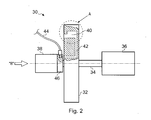
- FIG. 2 Shown in Figure 2 is a gas turbine engine simulator 30 according to the present invention.
- the specific embodiment shown is a simulator configuration for the simulation of gas turbine engine rotor discs.
- the simulator 30 comprises a simulator rotor disc 32 mounted on a shaft 34 which extends through the disc 32.
- the shaft 34 is driven by a motor 36 at one end and supported by a bearing 38 at the other end.
- the simulator rotor disc 32 is provided with a cavity 40 at a position radially outward of the rotational axis of the disc 32.
- a passage 42 provides flow communication between the cavity 40 and a source of simulator coolant fluid, indicated diagrammatically by a pipeline 44 which ducts coolant flow by some suitable means from a non rotatable collar 46 provided around the shaft 34, to an inlet end of the passage 42.
- a source of simulator coolant fluid indicated diagrammatically by a pipeline 44 which ducts coolant flow by some suitable means from a non rotatable collar 46 provided around the shaft 34, to an inlet end of the passage 42.
- the means by which flow is communicated from the collar 46 to the inlet end of the passage 42 will not be described in detail here and is not central to understanding the present invention.
- the simulator rotor disc 32 has substantially the same maximum external dimensions as the rotor disc 22,24 in the engine 10 being simulated. Unlike an engine rotor disc, the simulator rotor disc 32 is manufactured from a material which has a density of less than 220kg/m 3 . Preferably the rotor 32 is made from material which has a density in the range of 20kg/m 3 to 220kg/m 3 . Typically the rotor 32 is made from a material which has a density of about 110kg/m 3 . In the present example the simulator rotor disc is primarily made from a foamed plastic material to optimise density, although it may also be made from a solid plastic material. The foamed plastic material has a closed cell structure.
- the cavity 40 is of rectangular form provided at a single location radially outward of the axis of rotation of the simulator 32.
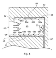
- FIG. 4 An enlarged view of the region of the simulator 32 in which the cavity 40 is provided, as indicated by the dotted circle "A" in Figure 2 and as viewed at the cross-section location C-C in Figure 3, is presented in Figure 4.
- the passage 42 provides flow communication between cavity 40 and a source of simulator coolant fluid, and a flow outlet 50 permits simulator coolant flow delivered by the passage 42 to be exhausted from the cavity 40, as shown by arrows 52.
- the cavity 40 is provided as a rectangular chamber having a roof 54 radially outward of a floor 56. Heater units 58,60 are provided in the roof 54 and floor 56 respectively. Thermally conductive plates 62,64 are fixed over the top of the heater units 58,60 respectively.
- Thermocouples 66a-e,68a-f are mounted on the thermally conductive plates 62,64 respectively, spacing the heater units 58,60 apart from the thermocouples 66a-e, 68a-f.
- the means by which power is supplied to operate the heater units 58,60 or the means by which outputs are received from the thermocouple 66a-e,68a-f is by some suitable means not discussed here and which is not central to the understanding of the invention.
- the motor 36 drives the simulator rotor 32 at a variety of rotational speeds.
- One of the advantages of the present invention is that because of the low weight of the simulator rotor 32, the rotor 30 can be driven at rotational speeds substantially the same as the operational rotational speeds of the rotors 22,24 in the engine without becoming hazardous.
- a simulator rotor 32 the size of a typical rotor disc 22,24 for a gas turbine engine has sufficient structural integrity to withstand centrifugal forces without failing at speed in the range of about 3000 revolutions per minute to about 10,000 revolutions per minute.
- the simulated rotor has a maximum rotational speed of about 7000 revolutions per minute.
- the ratio of maximum rotational disc speed to maximum simulator rotational speed is not less than 1 but no greater than about 4.
- the maximum rotational speed achievable before the simulator disc 32 may fail is hence in the range of speeds up to the speed of a rotor 22,24 but not less than a quarter of the maximum rotational speed of the rotor 22,24.
- a ratio of maximum rotor 22,24 rotational disc speed to maximum simulator 32 rotational speed of about 1.6. is achievable without risking failure of the simulator disc 32.
- the embodiment presented in Figures 2 to 4 relates specifically to a simulator 32 for measuring heat transfer rates between coolant air at junction between a rotor disc 22,24 and the rotor blades 18,20.
- simulator coolant fluid is supplied to the cavity 40 via the passage 42.
- Heater units 58,60 raise the temperature of the thermally conductive plates 62,64 and the temperature is measured by thermocouples 60a-d and 68a-f. Heat will be transferred between the simulator coolant flow 52 passing over the thermocouples 66,68 and thermally conductive plates 62,64 causing a change in temperature along the thermally conductive plates 62,64, which is recorded by the thermocouples 66,68.
- the simulation is conducted at any desired rotor speed, acceleration or deceleration.
- the simulator gas fed into the cavity 40 via passage 42 is chosen from a group of fluids which has a density at rig operating conditions (ie substantially ambient atmospheric temperature and pressure) such that flow fields of an operational engine can be reproduced.
- a density at rig operating conditions ie substantially ambient atmospheric temperature and pressure
- carbon dioxide and argon are suitable for use as a simulator coolant fluid.
- plastic rotor disc 32 is safer to work with, and is considerably quicker and easier to balance than a metal disc.
- metal discs are subject to significant thermal conduction hence will affect the accuracy of the recorded heat transfer data, a problem which is exaggerated by running the simulation at close to ambient conditions rather than at engine running temperatures. That is to say heat loss from a metal simulator at low temperatures will cause large errors, but heat loss from a plastic rotor disc will be minor.
- the spatial resolution of the results taken from a metal disc will be less than that for a plastic disc because of heat conduction away from the heater unit through the disc material. That is to say, thermal conduction in directions parallel to the surface will effect the thermocouple readings, thereby reducing accuracy of the recorded temperature at a given location.
- the present invention could be easily modified to measure cooling of any rotatable component including rotor blades. Additionally it could be employed to calibrate instrumentation for rotatable components where it is required to calibrate the instrumentation under controlled conditions.
Landscapes
- Chemical & Material Sciences (AREA)
- Engineering & Computer Science (AREA)
- Combustion & Propulsion (AREA)
- Physics & Mathematics (AREA)
- General Physics & Mathematics (AREA)
- Management, Administration, Business Operations System, And Electronic Commerce (AREA)
- Turbine Rotor Nozzle Sealing (AREA)
- Structures Of Non-Positive Displacement Pumps (AREA)
Abstract
Description
- The invention concerns a gas turbine engine simulator.
- In particular it relates to a gas turbine engine simulator which includes a simulator rotor disc.
- The development of machinery with components which, in operation, rotate at high speeds frequently requires the use of test equipment to validate an engineering design. For example in the case of a compressor or turbine rotor disc for a gas turbine engine it may be required to simulate operational heat transfer rates at different locations on and within the disc. These can be measured using a scale model and correcting the results obtained to allow for physical differences between the model and the actual disc. Alternatively an instrumented compressor or turbine rotor disc can be employed, but this will require adequate containment to prevent harm to equipment and personnel in case the disc should fail. High speed rotating rotor discs can cause severe damage if they fail, and so experiment rigs are usually installed in heavily shielded rooms or pits. Alternatively compressor or turbine rotor discs can be instrumented and run at a rotational speed significantly lower than operational speeds to obviate the need for containment, but the results obtained will need correcting to scale them to operational conditions. Such scaling calculations inherently introduce errors into the derived results.
- According to the present invention there is provided a gas turbine engine simulator comprising a simulator rotor disc which has substantially the same maximum external dimensions as a rotor disc and is manufactured from a material which has a density of less than 220 kg/m3.
- The present invention overcomes problems with the prior art by providing a simulator which more closely mimics the operation of a rotor disc whilst avoiding the need for substantial disc failure containment measures. By manufacturing the rotor disc from a material of low density to produce a simulator rotor disc having a mass significantly lower than that of the rotor disc being simulated, the inertia and stresses of the simulated disc will be low and hence disc failure containment measures need only be minimal. Typically a rotor disc for a gas turbine engine has a density of about 9,000 kg/m3, resulting in a mass of about 80 kg. Hence a simulator disc having a significantly lower density will have a significantly lower mass, and will be much safer to work with. In addition, the forces generated by lack of balance of the rotating disk are similarly reduced by the use of a low mass disc, hence a simulator rotor disc according to the present invention is easier to balance, mount and operate than a rotor disc. By making the simulator rotor disc to substantially the same size and geometry as the rotor disc being simulated aerodynamic differences between the simulated and operational conditions are minimised.
- Preferably the simulator rotor disc substantially comprises a plastic material. Plastic is generally of considerably lower density than metal and has high resistance to stress.
- Preferably the simulator rotor disc comprises a foamed plastic material. Foaming a material further reduces it density, hence a simulator of a given size made from a foamed plastic will be lighter than a simulator rotor disc made from a solid plastic.
- Preferably the foamed plastic material is provided as a closed cell structure. A closed cell structure is more robust than an open cell structure since it contains less flaws and failure initiation points, thereby increasing its resistance to failure when rotated a high speeds.
- Preferably the simulator rotor disc is provided with a cavity in flow communication with a source of simulator coolant fluid, at least one flow outlet, at least one heater unit and at least one thermocouple mounted within said cavity for the measurement of simulator coolant fluid temperature within said cavity. This enables the measurement of heat transfer characteristics of a turbine disc at a given location. In particular it allows for estimation of the heat transfer between a rotor disc and coolant air and heat transfer between rotor blades and coolant air in the region where they are attached to the rotor disc.
- Preferably the simulator coolant fluid is chosen from a group comprising carbon dioxide and argon. The simulator coolant fluid can be any fluid which has a density at rig operating conditions (ie substantially ambient atmospheric temperature and pressure) such that flow fields of an operational engine can be reproduced.
- Preferably the simulator has a maximum rotational speed in the range of about 3,000 revolutions per minute to about 10,000 revolutions per minute. That is to say, the simulator rotor can be rotated at speeds substantially the same as the rotor.
- The present invention will now be described, by way of example only, with reference to the accompanying figures in which:
- Figure 1 shows a diagrammatic representation of a gas turbine engine (PRIOR ART);
- Figure 2 shows a side view of a gas turbine simulator according to the present invention;
- Figure 3 shows an end view of the simulator as seen from direction indicated by arrow B in Figure 2; and
- Figure 4 shows an enlarged view of the section A circled in Figure 2, and the cross-sectional view C-C indicated in Figure 3.
- A diagrammatic representation of a typical
gas turbine engine 10 is presented in Figure 1 (PRIOR ART). Theengine 10 comprises acompressor section 12, acombustion section 14 and aturbine section 16. Thecompressor 12 andturbine 14 containrotor blades rotor discs turbine rotor disc 24 to therotor blade 20 throughpassages 26 to cool therotor disc 24 androtor blades 26. - Shown in Figure 2 is a gas
turbine engine simulator 30 according to the present invention. The specific embodiment shown is a simulator configuration for the simulation of gas turbine engine rotor discs. Thesimulator 30 comprises asimulator rotor disc 32 mounted on ashaft 34 which extends through thedisc 32. Theshaft 34 is driven by amotor 36 at one end and supported by abearing 38 at the other end. Thesimulator rotor disc 32 is provided with acavity 40 at a position radially outward of the rotational axis of thedisc 32. Apassage 42 provides flow communication between thecavity 40 and a source of simulator coolant fluid, indicated diagrammatically by apipeline 44 which ducts coolant flow by some suitable means from a nonrotatable collar 46 provided around theshaft 34, to an inlet end of thepassage 42. The means by which flow is communicated from thecollar 46 to the inlet end of thepassage 42 will not be described in detail here and is not central to understanding the present invention. - The
simulator rotor disc 32 has substantially the same maximum external dimensions as therotor disc engine 10 being simulated. Unlike an engine rotor disc, thesimulator rotor disc 32 is manufactured from a material which has a density of less than 220kg/m3. Preferably therotor 32 is made from material which has a density in the range of 20kg/m3 to 220kg/m3. Typically therotor 32 is made from a material which has a density of about 110kg/m3. In the present example the simulator rotor disc is primarily made from a foamed plastic material to optimise density, although it may also be made from a solid plastic material. The foamed plastic material has a closed cell structure. - As shown in Figure 3, in this embodiment the
cavity 40 is of rectangular form provided at a single location radially outward of the axis of rotation of thesimulator 32. - An enlarged view of the region of the
simulator 32 in which thecavity 40 is provided, as indicated by the dotted circle "A" in Figure 2 and as viewed at the cross-section location C-C in Figure 3, is presented in Figure 4. Thepassage 42 provides flow communication betweencavity 40 and a source of simulator coolant fluid, and aflow outlet 50 permits simulator coolant flow delivered by thepassage 42 to be exhausted from thecavity 40, as shown byarrows 52. Thecavity 40 is provided as a rectangular chamber having aroof 54 radially outward of afloor 56.Heater units roof 54 andfloor 56 respectively. Thermallyconductive plates heater units Thermocouples 66a-e,68a-f are mounted on the thermallyconductive plates heater units thermocouples 66a-e, 68a-f. The means by which power is supplied to operate theheater units thermocouple 66a-e,68a-f is by some suitable means not discussed here and which is not central to the understanding of the invention. - In operation the
motor 36 drives thesimulator rotor 32 at a variety of rotational speeds. One of the advantages of the present invention is that because of the low weight of thesimulator rotor 32, therotor 30 can be driven at rotational speeds substantially the same as the operational rotational speeds of therotors simulator rotor 32 the size of atypical rotor disc - Hence the ratio of maximum rotational disc speed to maximum simulator rotational speed is not less than 1 but no greater than about 4. The maximum rotational speed achievable before the
simulator disc 32 may fail is hence in the range of speeds up to the speed of arotor rotor maximum rotor maximum simulator 32 rotational speed of about 1.6. is achievable without risking failure of thesimulator disc 32. - The embodiment presented in Figures 2 to 4 relates specifically to a
simulator 32 for measuring heat transfer rates between coolant air at junction between arotor disc rotor blades simulator 32 is rotating) simulator coolant fluid is supplied to thecavity 40 via thepassage 42.Heater units conductive plates simulator coolant flow 52 passing over the thermocouples 66,68 and thermallyconductive plates conductive plates - The simulator gas fed into the
cavity 40 viapassage 42 is chosen from a group of fluids which has a density at rig operating conditions (ie substantially ambient atmospheric temperature and pressure) such that flow fields of an operational engine can be reproduced. Experiments have shown that carbon dioxide and argon are suitable for use as a simulator coolant fluid. - The advantage of such a simulator is that details of operational characteristics of rotor discs can be determined cheaply and quickly (ie without having to use original engine parts or provide containment for a metal rotor disc). Additionally there will be fewer errors in the derived results because the data is recorded from a component of similar size and running at similar speeds and hence require only minor correction and/or normalisation.
- Further advantages of using a
plastic rotor disc 32 over ametal rotor disc - The present invention could be easily modified to measure cooling of any rotatable component including rotor blades. Additionally it could be employed to calibrate instrumentation for rotatable components where it is required to calibrate the instrumentation under controlled conditions.
Claims (14)
- A gas turbine engine simulator (30) comprises a simulator rotor disc (32) which has substantially the same maximum external dimensions as a rotor disc (22,24) and is manufactured from a material which has a density of less than 220 kg/m3.
- A simulator (30) as claimed in claim 1 wherein the simulator rotor disc (32) is manufactured from a material which has a density in the range of about 20 kg/m3 to about 220 kg/m3.
- A simulator (30) as claimed in claim 1 or claim 2 wherein the simulator rotor disc (32) is manufactured from a material which has a density of about 110 kg/m3.
- A simulator (30) as claimed in any one of claims 1 to 3 wherein the simulator rotor disc (32) substantially comprises a plastic material.
- A simulator (30) as claimed in claim 4 wherein the simulator rotor disc comprises a foamed plastic material.
- A simulator (30) as claimed in claim 5 wherein the foamed plastic material is provided as a closed cell structure.
- A simulator (30) as claimed in any one of the preceding claims wherein the simulator rotor disc (32) is provided with a cavity (40) in flow communication with a source of simulator coolant fluid, at least one flow outlet (50), at least one heater unit (58,60) and at least one thermocouple (68) mounted within said cavity (40) for the measurement of simulator coolant fluid temperature within said cavity (40).
- A simulator (30) as claimed in claim 7 wherein the at least one heater unit (58,60) and the at least one thermocouple (68) are spaced apart from one another by a thermally conductive plate (62,64) provided within said cavity (40).
- A simulator (30) as claimed in claim 7 or claim 8 wherein the at least one heater unit (58,60) is mounted on the roof (54) and/or the floor (56) of the cavity, the at least one thermocouple (68) is mounted on the thermally conductive plate (62,64) and spaced apart from the heater unit (58,60) by the thermally conductive plate (62,64).
- A simulator (30) as claimed in any one of claims 7 to 9 wherein the simulator coolant fluid is chosen from a group comprising carbon dioxide and argon.
- A simulator (30) as claimed in any one of the preceding claims wherein the simulator rotor (32) has a maximum rotational speed in the range of about 3,000 revolutions per minute to about 10,000 revolutions per minute.
- A simulator (30) as claimed in any one of the preceding claims wherein the simulated rotor (32) has a maximum rotational speed of about 7,000 revolutions per minute.
- A simulator (30) as claimed in any one of the preceding claims wherein a ratio of maximum rotor rotational disc (22,24) speed to maximum simulator (30) rotational speed is no less than about 1 but no greater than about 4.
- A simulator (30) as claimed in claim 13 wherein the ratio of maximum rotor rotational disc (22,24) speed to maximum simulator (30) rotational speed is about 1.6.
Applications Claiming Priority (1)
| Application Number | Priority Date | Filing Date | Title |
|---|---|---|---|
| GB0521215A GB2432426B8 (en) | 2005-10-19 | 2005-10-19 | Gas turbine engine simulator |
Publications (3)
| Publication Number | Publication Date |
|---|---|
| EP1777507A2 true EP1777507A2 (en) | 2007-04-25 |
| EP1777507A3 EP1777507A3 (en) | 2008-07-16 |
| EP1777507B1 EP1777507B1 (en) | 2017-03-15 |
Family
ID=35451990
Family Applications (1)
| Application Number | Title | Priority Date | Filing Date |
|---|---|---|---|
| EP06255168.4A Ceased EP1777507B1 (en) | 2005-10-19 | 2006-10-06 | Gas turbine engine simulator |
Country Status (3)
| Country | Link |
|---|---|
| US (1) | US7717668B2 (en) |
| EP (1) | EP1777507B1 (en) |
| GB (1) | GB2432426B8 (en) |
Cited By (1)
| Publication number | Priority date | Publication date | Assignee | Title |
|---|---|---|---|---|
| CN106404406A (en) * | 2016-10-17 | 2017-02-15 | 西安福赛斯机电科技有限公司 | Aero-engine environment simulation device |
Families Citing this family (3)
| Publication number | Priority date | Publication date | Assignee | Title |
|---|---|---|---|---|
| CN105300695B (en) * | 2015-09-22 | 2018-04-13 | 中国航空工业集团公司沈阳发动机设计研究所 | A kind of turbine inside rotating disc cavities fluid interchange formula correction factor determines method |
| US20180216466A1 (en) * | 2016-10-14 | 2018-08-02 | Pw Power Systems, Inc. | Methods and systems for rotating component balancing |
| US11319880B2 (en) | 2018-10-26 | 2022-05-03 | Rolls-Royce North American Technologies, Inc. | Electrical controller for engine-driven electric machine |
Citations (1)
| Publication number | Priority date | Publication date | Assignee | Title |
|---|---|---|---|---|
| US2929755A (en) | 1958-07-24 | 1960-03-22 | Orenda Engines Ltd | Plastic blades for gas turbine engines |
Family Cites Families (10)
| Publication number | Priority date | Publication date | Assignee | Title |
|---|---|---|---|---|
| US3611601A (en) * | 1970-02-17 | 1971-10-12 | Product Design And Mfg Corp | Rotating wheel tire display |
| US3695778A (en) * | 1970-09-18 | 1972-10-03 | Trw Inc | Turbine blade |
| US5080496A (en) * | 1990-06-25 | 1992-01-14 | General Electric Company | Method and apparatus for compensated temperature prediction |
| US5191711A (en) * | 1991-12-23 | 1993-03-09 | Allied-Signal Inc. | Compressor or turbine blade manufacture |
| JP3002139U (en) * | 1994-03-18 | 1994-09-20 | 株式会社トイボックス | Disc launch toy |
| US5996564A (en) * | 1998-08-12 | 1999-12-07 | Kids Only | Disc discharging device |
| US6901810B1 (en) * | 2002-08-08 | 2005-06-07 | Williams International Co. L.L.C. | Method of cyclic testing |
| US6749394B2 (en) * | 2002-09-25 | 2004-06-15 | Bruce E. Boatner | Rotating display apparatus |
| US7108576B2 (en) * | 2004-02-13 | 2006-09-19 | Poof Products, Inc. | Foam projectile exhibiting an illuminating element |
| US7004813B2 (en) * | 2004-04-01 | 2006-02-28 | Cyi, Inc. | Toy gun with glowing projectiles and method of providing glowing projectiles to a toy gun |
-
2005
- 2005-10-19 GB GB0521215A patent/GB2432426B8/en not_active Expired - Fee Related
-
2006
- 2006-10-06 EP EP06255168.4A patent/EP1777507B1/en not_active Ceased
- 2006-10-19 US US11/583,068 patent/US7717668B2/en not_active Expired - Fee Related
Patent Citations (1)
| Publication number | Priority date | Publication date | Assignee | Title |
|---|---|---|---|---|
| US2929755A (en) | 1958-07-24 | 1960-03-22 | Orenda Engines Ltd | Plastic blades for gas turbine engines |
Cited By (1)
| Publication number | Priority date | Publication date | Assignee | Title |
|---|---|---|---|---|
| CN106404406A (en) * | 2016-10-17 | 2017-02-15 | 西安福赛斯机电科技有限公司 | Aero-engine environment simulation device |
Also Published As
| Publication number | Publication date |
|---|---|
| GB2432426B (en) | 2007-09-26 |
| EP1777507B1 (en) | 2017-03-15 |
| EP1777507A3 (en) | 2008-07-16 |
| GB2432426B8 (en) | 2007-11-20 |
| GB0521215D0 (en) | 2005-11-23 |
| US20070207039A1 (en) | 2007-09-06 |
| GB2432426A8 (en) | 2007-10-10 |
| US7717668B2 (en) | 2010-05-18 |
| GB2432426A (en) | 2007-05-23 |
Similar Documents
| Publication | Publication Date | Title |
|---|---|---|
| US8419270B2 (en) | Systems and methods for producing thermal mechanical fatigue on gas turbine rotors in a spin test environment | |
| JP7012428B2 (en) | Passive flow modulation of cooling flow using telemetry | |
| JP2017155744A (en) | Method and system for piping failure detection | |
| Epstein et al. | The MIT blowdown turbine facility | |
| EP1777507B1 (en) | Gas turbine engine simulator | |
| Barabas et al. | Experimental and numerical determination of pressure and velocity distribution inside a rotor-stator cavity at very high circumferential Reynolds numbers | |
| Hubinka et al. | Design and construction of a two shaft test turbine for investigation of mid turbine frame flows | |
| Pernak et al. | Flow and heat transfer in rotating compressor cavities with inverted shroud-throughflow temperature differences | |
| CN113358386B (en) | A variable temperature field loading and detection system for rotating machinery | |
| Haldeman et al. | Fully cooled single stage HP transonic turbine—Part I: Influence of cooling mass flow variations and inlet temperature profiles on blade internal and external aerodynamics | |
| Shirley | An experimental investigation of a low Reynolds number, high Mach number centrifugal compressor | |
| Childs et al. | Internal air systems experimental rig best practice | |
| Millward et al. | Experimental investigation into the effects of rotating and static bolts on both windage heating and local heat transfer coefficients in a rotor/stator cavity | |
| Němec et al. | Adaptable test rig for two-stage axial turbine | |
| Cui et al. | Numerical and experimental investigation of heat transfer in a low flow single stage centrifugal compressor | |
| CN203259437U (en) | High-speed rotating skiving testing machine | |
| CN203629597U (en) | Fixing and protecting device for installing transmitting circuit in high-speed rotating machine | |
| CN115638989A (en) | A feeding device and method for high-speed rotary scraping test of aeroengine grate-bush structure | |
| US20150003965A1 (en) | Turbomachine for generating power having a temperature measurement device in a region of the rotor | |
| CN101813574B (en) | Mechanical tripping operation function verification device in fluid environment | |
| Payne et al. | Experimental investigation on the effect of varying purge flow in a newly commissioned single stage turbine test facility | |
| Selvam et al. | Transient thermal analysis of gas turbine shut down physics: Normal and forced cooling | |
| Rudolph et al. | Innovative design features of the SGT5-8000h turbine And secondary air system | |
| RU2556304C1 (en) | Stand for testing gas-dynamic bearings | |
| Kool et al. | Advanced seal test rig validation and operation |
Legal Events
| Date | Code | Title | Description |
|---|---|---|---|
| PUAI | Public reference made under article 153(3) epc to a published international application that has entered the european phase |
Free format text: ORIGINAL CODE: 0009012 |
|
| AK | Designated contracting states |
Kind code of ref document: A2 Designated state(s): AT BE BG CH CY CZ DE DK EE ES FI FR GB GR HU IE IS IT LI LT LU LV MC NL PL PT RO SE SI SK TR |
|
| AX | Request for extension of the european patent |
Extension state: AL BA HR MK YU |
|
| PUAL | Search report despatched |
Free format text: ORIGINAL CODE: 0009013 |
|
| AK | Designated contracting states |
Kind code of ref document: A3 Designated state(s): AT BE BG CH CY CZ DE DK EE ES FI FR GB GR HU IE IS IT LI LT LU LV MC NL PL PT RO SE SI SK TR |
|
| AX | Request for extension of the european patent |
Extension state: AL BA HR MK RS |
|
| 17P | Request for examination filed |
Effective date: 20081202 |
|
| AKX | Designation fees paid |
Designated state(s): DE FR GB |
|
| 17Q | First examination report despatched |
Effective date: 20090309 |
|
| RAP1 | Party data changed (applicant data changed or rights of an application transferred) |
Owner name: ROLLS-ROYCE PLC |
|
| GRAP | Despatch of communication of intention to grant a patent |
Free format text: ORIGINAL CODE: EPIDOSNIGR1 |
|
| STAA | Information on the status of an ep patent application or granted ep patent |
Free format text: STATUS: GRANT OF PATENT IS INTENDED |
|
| INTG | Intention to grant announced |
Effective date: 20161220 |
|
| GRAS | Grant fee paid |
Free format text: ORIGINAL CODE: EPIDOSNIGR3 |
|
| GRAA | (expected) grant |
Free format text: ORIGINAL CODE: 0009210 |
|
| STAA | Information on the status of an ep patent application or granted ep patent |
Free format text: STATUS: THE PATENT HAS BEEN GRANTED |
|
| AK | Designated contracting states |
Kind code of ref document: B1 Designated state(s): DE FR GB |
|
| REG | Reference to a national code |
Ref country code: GB Ref legal event code: FG4D |
|
| REG | Reference to a national code |
Ref country code: DE Ref legal event code: R096 Ref document number: 602006051960 Country of ref document: DE |
|
| REG | Reference to a national code |
Ref country code: FR Ref legal event code: PLFP Year of fee payment: 12 |
|
| REG | Reference to a national code |
Ref country code: DE Ref legal event code: R097 Ref document number: 602006051960 Country of ref document: DE |
|
| PLBE | No opposition filed within time limit |
Free format text: ORIGINAL CODE: 0009261 |
|
| STAA | Information on the status of an ep patent application or granted ep patent |
Free format text: STATUS: NO OPPOSITION FILED WITHIN TIME LIMIT |
|
| 26N | No opposition filed |
Effective date: 20171218 |
|
| REG | Reference to a national code |
Ref country code: FR Ref legal event code: PLFP Year of fee payment: 13 |
|
| PGFP | Annual fee paid to national office [announced via postgrant information from national office to epo] |
Ref country code: GB Payment date: 20201027 Year of fee payment: 15 Ref country code: FR Payment date: 20201027 Year of fee payment: 15 |
|
| PGFP | Annual fee paid to national office [announced via postgrant information from national office to epo] |
Ref country code: DE Payment date: 20201228 Year of fee payment: 15 |
|
| REG | Reference to a national code |
Ref country code: DE Ref legal event code: R119 Ref document number: 602006051960 Country of ref document: DE |
|
| GBPC | Gb: european patent ceased through non-payment of renewal fee |
Effective date: 20211006 |
|
| PG25 | Lapsed in a contracting state [announced via postgrant information from national office to epo] |
Ref country code: GB Free format text: LAPSE BECAUSE OF NON-PAYMENT OF DUE FEES Effective date: 20211006 Ref country code: DE Free format text: LAPSE BECAUSE OF NON-PAYMENT OF DUE FEES Effective date: 20220503 |
|
| PG25 | Lapsed in a contracting state [announced via postgrant information from national office to epo] |
Ref country code: FR Free format text: LAPSE BECAUSE OF NON-PAYMENT OF DUE FEES Effective date: 20211031 |