EP1777412A1 - Capacity control valve for variable displacement swash plate type compressor - Google Patents
Capacity control valve for variable displacement swash plate type compressor Download PDFInfo
- Publication number
- EP1777412A1 EP1777412A1 EP05758312A EP05758312A EP1777412A1 EP 1777412 A1 EP1777412 A1 EP 1777412A1 EP 05758312 A EP05758312 A EP 05758312A EP 05758312 A EP05758312 A EP 05758312A EP 1777412 A1 EP1777412 A1 EP 1777412A1
- Authority
- EP
- European Patent Office
- Prior art keywords
- valve
- hole
- control valve
- displacement control
- chamber
- Prior art date
- Legal status (The legal status is an assumption and is not a legal conclusion. Google has not performed a legal analysis and makes no representation as to the accuracy of the status listed.)
- Granted
Links
- 238000006073 displacement reaction Methods 0.000 title claims abstract description 91
- 238000004891 communication Methods 0.000 claims description 35
- 239000000463 material Substances 0.000 claims description 13
- 229910000838 Al alloy Inorganic materials 0.000 claims description 5
- 239000011347 resin Substances 0.000 claims description 5
- 229920005989 resin Polymers 0.000 claims description 5
- 238000005192 partition Methods 0.000 description 10
- 230000007423 decrease Effects 0.000 description 7
- 238000005299 abrasion Methods 0.000 description 6
- 238000004378 air conditioning Methods 0.000 description 4
- 230000004048 modification Effects 0.000 description 4
- 238000012986 modification Methods 0.000 description 4
- 239000003507 refrigerant Substances 0.000 description 4
- 238000005057 refrigeration Methods 0.000 description 4
- 230000000694 effects Effects 0.000 description 1
- 230000005284 excitation Effects 0.000 description 1
- 238000003780 insertion Methods 0.000 description 1
- 230000037431 insertion Effects 0.000 description 1
- 238000007789 sealing Methods 0.000 description 1
Images



Classifications
-
- F—MECHANICAL ENGINEERING; LIGHTING; HEATING; WEAPONS; BLASTING
- F04—POSITIVE - DISPLACEMENT MACHINES FOR LIQUIDS; PUMPS FOR LIQUIDS OR ELASTIC FLUIDS
- F04B—POSITIVE-DISPLACEMENT MACHINES FOR LIQUIDS; PUMPS
- F04B27/00—Multi-cylinder pumps specially adapted for elastic fluids and characterised by number or arrangement of cylinders
- F04B27/08—Multi-cylinder pumps specially adapted for elastic fluids and characterised by number or arrangement of cylinders having cylinders coaxial with, or parallel or inclined to, main shaft axis
- F04B27/14—Control
- F04B27/16—Control of pumps with stationary cylinders
- F04B27/18—Control of pumps with stationary cylinders by varying the relative positions of a swash plate and a cylinder block
- F04B27/1804—Controlled by crankcase pressure
-
- F—MECHANICAL ENGINEERING; LIGHTING; HEATING; WEAPONS; BLASTING
- F04—POSITIVE - DISPLACEMENT MACHINES FOR LIQUIDS; PUMPS FOR LIQUIDS OR ELASTIC FLUIDS
- F04B—POSITIVE-DISPLACEMENT MACHINES FOR LIQUIDS; PUMPS
- F04B27/00—Multi-cylinder pumps specially adapted for elastic fluids and characterised by number or arrangement of cylinders
- F04B27/08—Multi-cylinder pumps specially adapted for elastic fluids and characterised by number or arrangement of cylinders having cylinders coaxial with, or parallel or inclined to, main shaft axis
- F04B27/14—Control
- F04B27/16—Control of pumps with stationary cylinders
- F04B27/18—Control of pumps with stationary cylinders by varying the relative positions of a swash plate and a cylinder block
- F04B27/1804—Controlled by crankcase pressure
- F04B2027/1822—Valve-controlled fluid connection
- F04B2027/1827—Valve-controlled fluid connection between crankcase and discharge chamber
-
- F—MECHANICAL ENGINEERING; LIGHTING; HEATING; WEAPONS; BLASTING
- F04—POSITIVE - DISPLACEMENT MACHINES FOR LIQUIDS; PUMPS FOR LIQUIDS OR ELASTIC FLUIDS
- F04B—POSITIVE-DISPLACEMENT MACHINES FOR LIQUIDS; PUMPS
- F04B27/00—Multi-cylinder pumps specially adapted for elastic fluids and characterised by number or arrangement of cylinders
- F04B27/08—Multi-cylinder pumps specially adapted for elastic fluids and characterised by number or arrangement of cylinders having cylinders coaxial with, or parallel or inclined to, main shaft axis
- F04B27/14—Control
- F04B27/16—Control of pumps with stationary cylinders
- F04B27/18—Control of pumps with stationary cylinders by varying the relative positions of a swash plate and a cylinder block
- F04B27/1804—Controlled by crankcase pressure
- F04B2027/184—Valve controlling parameter
- F04B2027/1854—External parameters
Definitions
- the present invention relates to a displacement control valve of a variable displacement inclined plate-type compressor, and specifically, relates to a displacement control valve incorporated into a variable displacement inclined plate-type compressor which is suitable for use in a refrigeration cycle of an air conditioning system for vehicles.
- Patent Document 1 discloses a displacement control valve of a variable displacement inclined plate-type compressor for controlling a discharge displacement of the compressor by opening and closing a valve hole formed in a communication path between a discharge chamber and a crank chamber of the compressor, the displacement control valve including the valve hole always communicating with the crank chamber, a valve body for opening and closing the valve hole, and an electromagnetic solenoid for driving the valve body.
- a force applied to the valve body at the time of valve closing is represented by the following equation (1).
- the following equation (1) stands on the premise that the crank chamber pressure decreases down to a pressure almost equal to a suction pressure at the time of valve closing.
- F f 1 - fs + Pd - Ps ⁇ Sv + fs ⁇
- an object of the present invention is to provide a displacement control valve of a variable displacement inclined plate-type compressor, which can be made smaller than that disclosed in Patent Document 1.
- a displacement control valve of a variable displacement inclined plate-type compressor is provided as a displacement control valve for controlling a discharge displacement of the compressor by opening and closing a communication path between a discharge chamber and a crank chamber of the compressor.
- the displacement control valve comprises a valve hole formed in the communication path and always communicating with the discharge chamber, a valve body for opening and closing the valve hole, a support hole provided coaxially with the valve hole, a support rod slidably inserted into the support hole and connected to the valve body, an electromagnetic solenoid for driving the valve body, and a pressure sensing chamber for introducing a suction pressure or crank chamber pressure of the compressor into an end section of the support rod which is on a side opposite to a side of the valve body.
- a force F applied to the valve body at the time of valve closing is represented by the following equation (2).
- the following equation (2) stands on the premise that the crank chamber pressure decreases down to a pressure almost equal to a suction pressure at the time of valve closing.
- F f 1 - fs ⁇ Pd - Ps ⁇ Sv - Sr
- the force fs of the releasing spring of the electromagnetic solenoid may be set at (Pd-Ps)x(Sv-Sr) or more.
- This spring force (Pd-Ps)x(Sv-Sr) is clearly smaller than the spring force (Pd-Ps)Sv+fs' required for the displacement control valve in the aforementioned Patent Document 1. Therefore, the displacement control valve according to the present invention can be made smaller than the displacement control valve of Patent Document 1.
- a cross-sectional area of the valve hole is set nearly equal to but greater than a cross-sectional area of the support rod.
- a contact part of the valve hole with the valve body is made of a hard material.
- valve hole and the support hole are integrally formed by a hard material.
- abrasion of the valve seat due to repeated contact of the valve body and abrasion of the support hole due to repeated slide of the support rod may be suppressed.
- the structure of the displacement control valve may be simplified as compared with a case where both are formed separately.
- a valve housing formed with the valve hole and the support hole and containing the valve body and the support rod is made from a resin or an aluminum alloy.
- the weight of the displacement control valve may be reduced.
- the force of the releasing spring of the electromagnetic solenoid required for forcibly opening the valve body can be made smaller than the force of the releasing spring required in the displacement control valve of Patent Document 1. Therefore, the displacement control valve according to the present invention can be made smaller than the displacement control valve of Patent Document 1.
- Figs. 1 and 2 depict a variable displacement inclined plate-type compressor having a displacement control valve according to a first embodiment of the present invention.
- a variable displacement inclined plate-type compressor 1 has a main shaft 10, a rotor 11 fixed to main shaft 10, and an inclined plate 12 supported by main shaft 10 at a condition capable of changing its inclination angle.
- Inclined plate 12 is connected to rotor 11 via a link mechanism 13 allowing the change of the inclination angle of inclined plate 12, and rotates synchronously with rotor 11 and main shaft 10.
- Piston 15 is engaged with inclined plate 12 via a pair of shoes 14 sliding on the periphery of inclined plate 12.
- Piston 15 is inserted into a cylinder bore 16a formed in a cylinder block 16.
- a plurality of pistons 15 are disposed around main shaft 10 at an interval with each other in the circumferential direction.
- a crank chamber 17 containing main shaft 10, rotor 11 and inclined plate 12 is formed by cylinder block 16 and front housing 18.
- Main shaft 10 extends to outside through front housing 18.
- a shaft seal member 19 is disposed for sealing the through portion of main shaft 10 in front housing 18.
- a pulley 20 is fixed at a tip portion of main shaft 10.
- pulley 20 is connected, for example, to an engine (not shown) via a belt (not shown).
- a cylinder head 23 forming a suction chamber 21 and a discharge chamber 22 is disposed at a position on a side of cylinder block 16 opposite to the side of front housing 18.
- Suction chamber 21 is connected to an evaporator (not shown), which is provided in an external circuit, for example, a refrigeration cycle of an air conditioning system for vehicles, via a suction port (not shown).
- Discharge chamber 22 is connected to a condenser (not shown), which is provided in an external circuit, for example, a refrigeration cycle of an air conditioning system for vehicles, via a discharge port (not shown).
- a valve plate 24 formed with suction hole 21a and discharge hole 22a communicating with cylinder bore 16a is provided between cylinder block 16 and cylinder head 23.
- a discharge valve and a suction valve (not shown) are attached to the valve plate 24.
- Crank chamber 17 and suction chamber 21 are communicated with each other via an orifice hole 24a formed on valve plate 24.
- Front housing 18, cylinder block 16, valve plate 24 and cylinder head 23 are integrally fastened by a plurality of through bolts 25 disposed at intervals along the circumference with a center of main shaft 10.
- a displacement control valve 2 for controlling the discharge displacement of variable displacement inclined plate-type compressor 1 is fitted into and fixed in a concave portion 26 which is formed in cylinder head 23 at a position adjacent to discharge chamber 22.
- displacement control valve 2 has a valve part 100 and an electromagnetic solenoid 120 connected to valve part 100.
- Valve part 100 has a cylindrical valve housing 101.
- Three closed spaces 27a, 27b and 27c are defined around valve housing 101 by two O-rings 101a and 101b tightly fitted onto the periphery of valve housing 101 and one O-ring 120a tightly fitted onto the periphery of the case of electromagnetic solenoid 120.
- a lateral partition wall 104 is formed for dividing the inside space of valve housing 101 into a pressure sensing chamber 102 on one end side and a valve chamber 103 on the other end side.
- a support hole 105 communicating with pressure sensing chamber 102 and a valve hole 106 communicating with valve chamber 103 are formed on lateral partition wall 104.
- Support hole 105 and valve hole 106 are disposed on the same axis and communicated with each other.
- a communication hole 107 extending in the radial direction through lateral partition wall 104 is formed in lateral partition wall 104 passing through the communicating portion between support hole 105 and valve hole 106.
- Pressure sensing chamber 102 communicates with suction chamber 21 via closed space 27a and a communication path 23a formed in cylinder head 23.
- Communication hole 107 always communicates with discharge chamber 22 via closed space 27b and a communication path 23b formed in cylinder head 23.
- Valve hole 106 communicating with communication hole 107 always communicates with discharge chamber 22.
- Valve chamber 103 communicates with crank chamber 17 via a communication hole 108 formed in valve housing 101, closed space 27c, a communication path 23c formed in cylinder head 23 and communication path 16b formed in cylinder block 16.
- valve body 109 for opening and closing valve hole 106 is disposed in valve chamber 103.
- a small-diameter rod 110 extending from valve body 109 is inserted into valve hole 106 at a movable condition with a gap.
- a support rod 111 integrally formed with the end portion of small-diameter rod 110 is slidably inserted into support hole 105.
- Valve part 100 is formed by a series of structures from valve housing 101 to support rod 111.
- Electromagnetic solenoid 120 has a case 121.
- the end portion of valve chamber 103 side of valve housing 101 is press fitted into one end of case 121.
- O-ring 120a for forming closed space 27c is fitted onto the periphery of the one end portion of case 121.
- Electromagnetic solenoid 120 has a fixed core 122 disposed in case 121, a movable core 123 disposed facing its one end to one end of fixed core 122, a releasing spring 124 for urging movable core 123 in a direction apart from the fixed core, an electromagnetic coil 125 surrounding fixed core 122 and movable core 123, and a rod 126 extending from movable core 123 through fixed core 122 at a condition capable of being floated.
- This rod 126 is formed integrally with valve body 109.
- the rod insertion hole formed in fixed core 122 and a space for containing movable core 123 are communicated with valve chamber 103, and is in a condition of the same pressure as that in valve chamber 103.
- crank chamber pressure gradually decreases.
- the crank chamber pressure decreases, the inclination angle of the inclined plate increases, and the discharge displacement of variable displacement inclined plate-type compressor 1 increases.
- valve body 109 opens valve hole 106.
- the high-pressure refrigerant gas in discharge chamber 22 is supplied into crank chamber 17 through the communication path formed by communication path 23b, closed space 27b, communication hole 107, valve hole 106, valve chamber 103, communication hole 108, closed space 27c, communication path 23c and communication path 16b.
- variable displacement inclined plate-type compressor 1 is controlled to be changed by the excitation and the degaussing of electromagnetic coil 125.
- a force F applied to valve body 109 at the time of valve closing is represented by the following equation (2).
- the following equation (2) stands on the premise that the pressure in crank chamber 17 decreases down to a pressure almost equal to a suction pressure at the time of valve closing and the pressure in valve chamber 103 is applied to the portion around movable core 123.
- F f 1 - fs ⁇ Pd - Ps ⁇ Sv - Sr
- the force fs of releasing spring 124 of the electromagnetic solenoid may be set at (Pd-Ps)x(Sv-Sr) or more.
- This spring force (Pd-Ps)x(Sv-Sr) is clearly smaller than the spring force (Pd-Ps)Sv+fs' required for the displacement control valve in the aforementioned Patent Document 1. Therefore, by using a small and weak releasing spring 124, displacement control valve 2 can be made smaller than the displacement control valve of Patent Document 1.
- pressure sensing chamber 102 may be communicated with crank chamber 17 instead of suction chamber 21.
- the cross-sectional area Sv of the valve hole is set nearly equal to but greater than the cross-sectional area Sr of the support rod.
- a structure may be employed wherein a ring member 112 made of a stainless-group material as a hard material is press fitted into lateral partition wall 104, and a contact part of valve hole 106 with valve body 109 is formed by the ring member 112.
- valve hole 106 and support hole 105 are integrally formed.
- valve hole 106 and support hole 105 from the stainless-group material which is a hard material, abrasion of the valve seat due to repeated contact of valve body 109 and abrasion of support hole 105 due to repeated slide of support rod 111 may be suppressed.
- the structure of displacement control valve 2 may be simplified as compared with a case where both are formed separately.
- valve housing 101 may be made from a resin or an aluminum alloy. By making valve housing 101 from a resin or an aluminum alloy, the weight of displacement control valve 2 may be reduced.
- Fig. 5 shows a displacement control valve of a variable displacement inclined plate-type compressor according to a second embodiment of the present invention.
- a displacement control valve 3 comprises a valve part 200 and an electromagnetic solenoid 220 connected to valve part 200.
- Valve part 200 has a cylindrical valve housing 201.
- Three closed spaces 27d, 27e and 27f are defined around valve housing 201 by two O-rings 201a and 201b tightly fitted onto the periphery of valve housing 201 and one O-ring 220a tightly fitted onto the periphery of the case of electromagnetic solenoid 220.
- a lateral partition wall 204 is formed for dividing the inside space of valve housing 201 into a valve chamber 202 on one end side and a pressure sensing chamber 203 on the other end side.
- a valve hole 205 communicating with valve chamber 202 and a support hole 206 communicating with pressure sensing chamber 203 are formed on lateral partition wall 204.
- Valve hole 205 and support hole 206 are disposed on the same axis and communicated with each other.
- a communication hole 207 extending in the radial direction through lateral partition wall 204 is formed in lateral partition wall 204 passing through the communicating portion between valve hole 205 and support hole 206.
- Pressure sensing chamber 203 communicates with suction chamber 21 or crank chamber 17 via a communication hole formed in valve housing 201, closed space 27d and a communication path (not shown) formed in cylinder head 23.
- Communication hole 207 communicates with discharge chamber 22 via closed space 27e and communication path 23b formed in cylinder head 23.
- Valve hole 205 communicating with communication hole 207 always communicates with discharge chamber 22.
- Valve chamber 202 communicates with crank chamber 17 via closed space 27f, a communication path (not shown) formed in cylinder head 23, and a communication path (not shown) formed in cylinder block 16.
- valve body 209 for opening and closing valve hole 205 is disposed in valve chamber 202.
- a small-diameter rod 210 extending from valve body 209 is inserted into valve hole 205 at a movable condition with a gap.
- a support rod 211 integrally formed with the end portion of small-diameter rod 210 is slidably inserted into support hole 206.
- Valve part 200 is formed by a series of structures from valve housing 201 to support rod 211.
- Electromagnetic solenoid 220 has a case 221.
- the end portion of pressure sensing chamber 203 side of valve housing 201 is press fitted into one end of case 221.
- O-ring 220a for forming closed space 27d is fitted onto the periphery of the one end portion of case 221.
- Electromagnetic solenoid 220 has a fixed core 222 disposed in case 221, a movable core 223 disposed facing its one end to one end of fixed core 222, a releasing spring 224 for urging movable core 223 in a direction apart from the fixed core, an electromagnetic coil 225 surrounding fixed core 222 and movable core 223, and a rod 226 extending from movable core 223.
- This rod 226 is formed integrally with support rod 211.
- the space forming the end portion of support rod 211 at the side apart from valve body 206 via rod 226 and containing movable core 223 is communicated with pressure sensing chamber 203. Therefore, the pressure in pressure sensing chamber 203, namely, the suction pressure or the crank chamber pressure is applied to movable core 223.
- displacement control valve 3 a force F applied to valve body 209 at the time of valve closing is same as the force F applied to valve body 109 at the time of valve closing in displacement control valve 2 of the first embodiment. Therefore, by using a small and weak releasing spring 224, displacement control valve 3 can be made smaller than the displacement control valve of the aforementioned Patent Document 1.
- the present invention can be applied broadly for displacement control valves of variable displacement inclined plate-type compressors.
Landscapes
- Engineering & Computer Science (AREA)
- Mechanical Engineering (AREA)
- General Engineering & Computer Science (AREA)
- Compressors, Vaccum Pumps And Other Relevant Systems (AREA)
- Control Of Positive-Displacement Pumps (AREA)
Abstract
Description
- The present invention relates to a displacement control valve of a variable displacement inclined plate-type compressor, and specifically, relates to a displacement control valve incorporated into a variable displacement inclined plate-type compressor which is suitable for use in a refrigeration cycle of an air conditioning system for vehicles.
- Patent Document 1 discloses a displacement control valve of a variable displacement inclined plate-type compressor for controlling a discharge displacement of the compressor by opening and closing a valve hole formed in a communication path between a discharge chamber and a crank chamber of the compressor, the displacement control valve including the valve hole always communicating with the crank chamber, a valve body for opening and closing the valve hole, and an electromagnetic solenoid for driving the valve body. In the displacement control valve disclosed in this Patent Document 1, a force applied to the valve body at the time of valve closing is represented by the following equation (1). The following equation (1) stands on the premise that the crank chamber pressure decreases down to a pressure almost equal to a suction pressure at the time of valve closing.

Where, - f(1) : electromagnetic force of the electromagnetic solenoid
- fs : urging force of a releasing spring of the electromagnetic solenoid
- Pd : discharge pressure
- Ps : suction pressure
- Sv : cross-sectional area of the valve hole
- fs' : urging force of a spring for pressing the valve body
- Patent Document 1:
JP-A-7-286581 - However, there are the following problems in the displacement control valve disclosed in the above-described Patent Document 1.
When the valve body is closed, because a pressure difference between the discharge pressure Pd and the suction pressure Ps urges the valve body in a direction of valve closing, in order to forcibly open the valve body by degaussing of the electromagnetic solenoid, it is necessary to set the urging force fs of the releasing spring of the electromagnetic solenoid at a value of (Pd-Ps)Sv+fs' or more. In order to forcibly open the valve body in a region with a high discharge pressure Pd, it is necessary to use a releasing spring with a great spring force fs, and it is necessary to generate a great electromagnetic force for exciting the electromagnetic solenoid and attracting a movable core against the spring force Fs of the releasing spring, and whereby, the electromagnetic solenoid becomes large. - Paying attention to the above-described problems, an object of the present invention is to provide a displacement control valve of a variable displacement inclined plate-type compressor, which can be made smaller than that disclosed in Patent Document 1.
- To achieve the above-described object, a displacement control valve of a variable displacement inclined plate-type compressor according to the present invention is provided as a displacement control valve for controlling a discharge displacement of the compressor by opening and closing a communication path between a discharge chamber and a crank chamber of the compressor. The displacement control valve comprises a valve hole formed in the communication path and always communicating with the discharge chamber, a valve body for opening and closing the valve hole, a support hole provided coaxially with the valve hole, a support rod slidably inserted into the support hole and connected to the valve body, an electromagnetic solenoid for driving the valve body, and a pressure sensing chamber for introducing a suction pressure or crank chamber pressure of the compressor into an end section of the support rod which is on a side opposite to a side of the valve body.
- In this displacement control valve, a force F applied to the valve body at the time of valve closing is represented by the following equation (2). The following equation (2) stands on the premise that the crank chamber pressure decreases down to a pressure almost equal to a suction pressure at the time of valve closing.

Where, - f(1) : electromagnetic force of the electromagnetic solenoid
- fs : urging force of a releasing spring of the electromagnetic solenoid
- Pd : discharge pressure
- Ps : suction pressure
- Sv : cross-sectional area of the valve hole
- Sr : cross-sectional area of the support rod
- In such a displacement control valve according to the present invention, in order to forcibly open the valve body by degaussing of the electromagnetic solenoid, the force fs of the releasing spring of the electromagnetic solenoid may be set at (Pd-Ps)x(Sv-Sr) or more. This spring force (Pd-Ps)x(Sv-Sr) is clearly smaller than the spring force (Pd-Ps)Sv+fs' required for the displacement control valve in the aforementioned Patent Document 1. Therefore, the displacement control valve according to the present invention can be made smaller than the displacement control valve of Patent Document 1.
- In the displacement control valve according to the present invention, it is preferred that a cross-sectional area of the valve hole is set nearly equal to but greater than a cross-sectional area of the support rod. Thus, if the cross-sectional area of the valve hole is set nearly equal to but greater than the cross-sectional area of the support rod, the discharge pressure operates in a valve opening direction at the time of valve closing. Therefore, by degaussing of the electromagnetic solenoid, the valve body is surely opened by the urging force of the releasing spring.
- Further, in the displacement control valve according to the present invention, it is preferred that a contact part of the valve hole with the valve body is made of a hard material. By making the contact part of the valve hole with the valve body, that is, the valve seat, from a hard material, abrasion of the valve seat due to repeated contact of the valve body may be suppressed.
- Further, in the displacement control valve according to the present invention, it is preferred that the valve hole and the support hole are integrally formed by a hard material. By forming the valve hole and the support hole from a hard material, abrasion of the valve seat due to repeated contact of the valve body and abrasion of the support hole due to repeated slide of the support rod may be suppressed. By forming the valve hole and the support hole integrally, the structure of the displacement control valve may be simplified as compared with a case where both are formed separately.
- Moreover, in the displacement control valve according to the present invention, it is preferred that a valve housing formed with the valve hole and the support hole and containing the valve body and the support rod is made from a resin or an aluminum alloy. Thus, by making the valve housing from a resin or an aluminum alloy, the weight of the displacement control valve may be reduced.
- In the displacement control valve of a variable displacement inclined plate-type compressor according to the present invention, the force of the releasing spring of the electromagnetic solenoid required for forcibly opening the valve body can be made smaller than the force of the releasing spring required in the displacement control valve of Patent Document 1. Therefore, the displacement control valve according to the present invention can be made smaller than the displacement control valve of Patent Document 1.
-
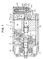
- [Fig. 1] Fig. 1 is a vertical sectional view of a variable displacement inclined plate-type compressor having a displacement control valve according to a first embodiment of the present invention.
- [Fig. 2] Figs. 2A and 2B are vertical sectional views of the displacement control valve according to the first embodiment, Fig. 2A shows a valve closing condition, and Fig. 2B shows a valve opening condition.
- [Fig. 3] Fig. 3A is a vertical sectional view of a displacement control valve according to a modification of the first embodiment, and Fig. 3B is an enlarged, partial, vertical sectional view thereof.
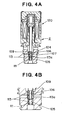
- [Fig. 4] Fig. 4A is a vertical sectional view of a displacement control valve according to another modification of the first embodiment, and Fig. 4B is an enlarged, partial, vertical sectional view thereof.
- [Fig. 5] Figs. 5A and 5B are vertical sectional views of a displacement control valve according to a second embodiment of the present invention, Fig. 5A shows a valve closing condition, and Fig. 5B shows a valve opening condition.
-
- 1: variable displacement inclined plate-type compressor
- 2, 3: displacement control valve
- 17: crank chamber
- 21: suction chamber
- 22: discharge chamber
- 26: concave portion
- 100, 200: valve part
- 101, 201: valve housing
- 102, 203: pressure sensing chamber
- 103, 202: valve chamber
- 105, 206: support hole
- 106, 205: valve hole
- 109, 209: valve body
- 111, 211: support rod
- 120, 220: electromagnetic solenoid
- Hereinafter, desirable embodiments of a displacement control valve of a variable displacement inclined plate-type compressor according to the present invention will be explained referring to figures.
- Figs. 1 and 2 depict a variable displacement inclined plate-type compressor having a displacement control valve according to a first embodiment of the present invention. As depicted in Fig. 1, a variable displacement inclined plate-type compressor 1 has a
main shaft 10, a rotor 11 fixed tomain shaft 10, and aninclined plate 12 supported bymain shaft 10 at a condition capable of changing its inclination angle.Inclined plate 12 is connected to rotor 11 via alink mechanism 13 allowing the change of the inclination angle ofinclined plate 12, and rotates synchronously with rotor 11 andmain shaft 10.Piston 15 is engaged withinclined plate 12 via a pair ofshoes 14 sliding on the periphery ofinclined plate 12.Piston 15 is inserted into a cylinder bore 16a formed in acylinder block 16. A plurality ofpistons 15 are disposed aroundmain shaft 10 at an interval with each other in the circumferential direction. - A crank chamber 17 containing
main shaft 10, rotor 11 andinclined plate 12 is formed bycylinder block 16 andfront housing 18.Main shaft 10 extends to outside throughfront housing 18. Ashaft seal member 19 is disposed for sealing the through portion ofmain shaft 10 infront housing 18. Apulley 20 is fixed at a tip portion ofmain shaft 10. In a case where variable displacement inclined plate-type compressor 1 is a compressor used for a refrigeration cycle of an air conditioning system for vehicles,pulley 20 is connected, for example, to an engine (not shown) via a belt (not shown). - A
cylinder head 23 forming asuction chamber 21 and adischarge chamber 22 is disposed at a position on a side ofcylinder block 16 opposite to the side offront housing 18.Suction chamber 21 is connected to an evaporator (not shown), which is provided in an external circuit, for example, a refrigeration cycle of an air conditioning system for vehicles, via a suction port (not shown).Discharge chamber 22 is connected to a condenser (not shown), which is provided in an external circuit, for example, a refrigeration cycle of an air conditioning system for vehicles, via a discharge port (not shown). - A
valve plate 24 formed withsuction hole 21a and discharge hole 22a communicating with cylinder bore 16a is provided betweencylinder block 16 andcylinder head 23. A discharge valve and a suction valve (not shown) are attached to thevalve plate 24. Crank chamber 17 andsuction chamber 21 are communicated with each other via anorifice hole 24a formed onvalve plate 24. -
Front housing 18,cylinder block 16,valve plate 24 andcylinder head 23 are integrally fastened by a plurality of throughbolts 25 disposed at intervals along the circumference with a center ofmain shaft 10. - A
displacement control valve 2 for controlling the discharge displacement of variable displacement inclined plate-type compressor 1 is fitted into and fixed in aconcave portion 26 which is formed incylinder head 23 at a position adjacent to dischargechamber 22. As shown in Figs. 1 and 2,displacement control valve 2 has avalve part 100 and anelectromagnetic solenoid 120 connected tovalve part 100. -
Valve part 100 has acylindrical valve housing 101. Threeclosed spaces valve housing 101 by two O-rings valve housing 101 and one O-ring 120a tightly fitted onto the periphery of the case ofelectromagnetic solenoid 120. - In
valve housing 101, alateral partition wall 104 is formed for dividing the inside space ofvalve housing 101 into apressure sensing chamber 102 on one end side and avalve chamber 103 on the other end side. Onlateral partition wall 104, asupport hole 105 communicating withpressure sensing chamber 102 and avalve hole 106 communicating withvalve chamber 103 are formed.Support hole 105 andvalve hole 106 are disposed on the same axis and communicated with each other. Acommunication hole 107 extending in the radial direction throughlateral partition wall 104 is formed inlateral partition wall 104 passing through the communicating portion betweensupport hole 105 andvalve hole 106. -
Pressure sensing chamber 102 communicates withsuction chamber 21 viaclosed space 27a and a communication path 23a formed incylinder head 23.Communication hole 107 always communicates withdischarge chamber 22 viaclosed space 27b and acommunication path 23b formed incylinder head 23.Valve hole 106 communicating withcommunication hole 107 always communicates withdischarge chamber 22.Valve chamber 103 communicates with crank chamber 17 via acommunication hole 108 formed invalve housing 101,closed space 27c, acommunication path 23c formed incylinder head 23 andcommunication path 16b formed incylinder block 16. - A
valve body 109 for opening and closingvalve hole 106 is disposed invalve chamber 103. A small-diameter rod 110 extending fromvalve body 109 is inserted intovalve hole 106 at a movable condition with a gap. Asupport rod 111 integrally formed with the end portion of small-diameter rod 110 is slidably inserted intosupport hole 105.Valve part 100 is formed by a series of structures fromvalve housing 101 to supportrod 111. -
Electromagnetic solenoid 120 has acase 121. The end portion ofvalve chamber 103 side ofvalve housing 101 is press fitted into one end ofcase 121. As aforementioned, O-ring 120a for formingclosed space 27c is fitted onto the periphery of the one end portion ofcase 121. -
Electromagnetic solenoid 120 has a fixedcore 122 disposed incase 121, amovable core 123 disposed facing its one end to one end of fixedcore 122, a releasingspring 124 for urgingmovable core 123 in a direction apart from the fixed core, anelectromagnetic coil 125 surrounding fixedcore 122 andmovable core 123, and arod 126 extending frommovable core 123 through fixedcore 122 at a condition capable of being floated. Thisrod 126 is formed integrally withvalve body 109. The rod insertion hole formed in fixedcore 122 and a space for containingmovable core 123 are communicated withvalve chamber 103, and is in a condition of the same pressure as that invalve chamber 103. - Next, the operation of
displacement control valve 2 will be explained.
As shown in Fig. 2A, whenelectromagnetic coil 125 is excited,movable core 123 is moved toward fixedcore 122 against the urging force of releasingspring 124, andvalve body 109 closesvalve hole 106. By this closing, the communication path betweendischarge chamber 22 and crank chamber 17, which is formed bycommunication path 23b,closed space 27b,communication hole 107,valve hole 106,valve chamber 103,communication hole 108,closed space 27c,communication path 23c andcommunication path 16b, is closed. Therefore, the high-pressure refrigerant gas indischarge chamber 22 is not supplied into crank chamber 17. Sinceorifice path 24a has an area enough to exhaust blow-by gas, which leaks from cylinder bore 16a to crank chamber 17 whenpiston 15 compresses refrigerant gas in cylinder bore 16a, intosuction chamber 21, the crank chamber pressure gradually decreases. When the crank chamber pressure decreases, the inclination angle of the inclined plate increases, and the discharge displacement of variable displacement inclined plate-type compressor 1 increases. - When
electromagnetic coil 125 is degaussed, as shown in Fig. 2B,movable core 123 moves in a direction apart from fixedcore 122 by the urging force of releasingspring 124, andvalve body 109 opensvalve hole 106. By this opening, the high-pressure refrigerant gas indischarge chamber 22 is supplied into crank chamber 17 through the communication path formed bycommunication path 23b,closed space 27b,communication hole 107,valve hole 106,valve chamber 103,communication hole 108,closed space 27c,communication path 23c andcommunication path 16b. By this supply of the high-pressure refrigerant gas, the crank chamber pressure elevates, the inclination angle of the inclined plate decreases, and the discharge displacement of variable displacement inclined plate-type compressor 1 decreases. - Thus, the discharge displacement of variable displacement inclined plate-type compressor 1 is controlled to be changed by the excitation and the degaussing of
electromagnetic coil 125. - In
displacement control valve 2, a force F applied tovalve body 109 at the time of valve closing is represented by the following equation (2). The following equation (2) stands on the premise that the pressure in crank chamber 17 decreases down to a pressure almost equal to a suction pressure at the time of valve closing and the pressure invalve chamber 103 is applied to the portion aroundmovable core 123.
Where, - f(1) : electromagnetic force of the electromagnetic solenoid
- fs : urging force of the releasing spring of the electromagnetic solenoid
- Pd : discharge pressure
- Ps : suction pressure
- Sv : cross-sectional area of the valve hole
- Sr : cross-sectional area of the support rod
- In such a
displacement control valve 2, in order to forciblyopen valve body 109 by degaussing ofelectromagnetic solenoid 120, the force fs of releasingspring 124 of the electromagnetic solenoid may be set at (Pd-Ps)x(Sv-Sr) or more. This spring force (Pd-Ps)x(Sv-Sr) is clearly smaller than the spring force (Pd-Ps)Sv+fs' required for the displacement control valve in the aforementioned Patent Document 1. Therefore, by using a small and weak releasingspring 124,displacement control valve 2 can be made smaller than the displacement control valve of Patent Document 1. - Where,
pressure sensing chamber 102 may be communicated with crank chamber 17 instead ofsuction chamber 21. - In the above-described
displacement control valve 2, it is preferred that the cross-sectional area Sv of the valve hole is set nearly equal to but greater than the cross-sectional area Sr of the support rod. By setting the cross-sectional area Sv of the valve hole nearly equal to but greater than the cross-sectional area Sr of the support rod, the discharge pressure Pd operates in a valve opening direction at the time of valve closing. Therefore, by degaussing of theelectromagnetic solenoid 120,valve body 109 is surely opened by the urging force of releasingspring 124. - As shown in a modification depicted in Fig. 3, in the above-described
displacement control valve 2, a structure may be employed wherein aring member 112 made of a stainless-group material as a hard material is press fitted intolateral partition wall 104, and a contact part ofvalve hole 106 withvalve body 109 is formed by thering member 112. By forming the contact part ofvalve hole 106 withvalve body 109, that is, the valve seat, from the stainless-group material which is a hard material, abrasion of the valve seat due to repeated contact ofvalve body 109 may be suppressed. - Further, as shown in another modification depicted in Fig. 4, a structure may be employed wherein a
ring member 113 of a stainless-group material, formed on its wall with a throughhole 113a communication withcommunication hole 107, is press fitted intolateral partition wall 104, andvalve hole 106 andsupport hole 105 are integrally formed. By formingvalve hole 106 andsupport hole 105 from the stainless-group material which is a hard material, abrasion of the valve seat due to repeated contact ofvalve body 109 and abrasion ofsupport hole 105 due to repeated slide ofsupport rod 111 may be suppressed. By integrally formingvalve hole 106 andsupport hole 105 byring member 113, the structure ofdisplacement control valve 2 may be simplified as compared with a case where both are formed separately. - Moreover,
valve housing 101 may be made from a resin or an aluminum alloy. By makingvalve housing 101 from a resin or an aluminum alloy, the weight ofdisplacement control valve 2 may be reduced. - Fig. 5 shows a displacement control valve of a variable displacement inclined plate-type compressor according to a second embodiment of the present invention. As shown in Fig. 5, a
displacement control valve 3 comprises avalve part 200 and anelectromagnetic solenoid 220 connected tovalve part 200. -
Valve part 200 has acylindrical valve housing 201. Threeclosed spaces valve housing 201 by two O-rings 201a and 201b tightly fitted onto the periphery ofvalve housing 201 and one O-ring 220a tightly fitted onto the periphery of the case ofelectromagnetic solenoid 220. - In
valve housing 201, alateral partition wall 204 is formed for dividing the inside space ofvalve housing 201 into avalve chamber 202 on one end side and apressure sensing chamber 203 on the other end side. Onlateral partition wall 204, avalve hole 205 communicating withvalve chamber 202 and asupport hole 206 communicating withpressure sensing chamber 203 are formed.Valve hole 205 andsupport hole 206 are disposed on the same axis and communicated with each other. Acommunication hole 207 extending in the radial direction throughlateral partition wall 204 is formed inlateral partition wall 204 passing through the communicating portion betweenvalve hole 205 andsupport hole 206. -
Pressure sensing chamber 203 communicates withsuction chamber 21 or crank chamber 17 via a communication hole formed invalve housing 201,closed space 27d and a communication path (not shown) formed incylinder head 23.Communication hole 207 communicates withdischarge chamber 22 viaclosed space 27e andcommunication path 23b formed incylinder head 23.Valve hole 205 communicating withcommunication hole 207 always communicates withdischarge chamber 22.Valve chamber 202 communicates with crank chamber 17 viaclosed space 27f, a communication path (not shown) formed incylinder head 23, and a communication path (not shown) formed incylinder block 16. - A
valve body 209 for opening and closingvalve hole 205 is disposed invalve chamber 202. A small-diameter rod 210 extending fromvalve body 209 is inserted intovalve hole 205 at a movable condition with a gap. Asupport rod 211 integrally formed with the end portion of small-diameter rod 210 is slidably inserted intosupport hole 206.Valve part 200 is formed by a series of structures fromvalve housing 201 to supportrod 211. -
Electromagnetic solenoid 220 has acase 221. The end portion ofpressure sensing chamber 203 side ofvalve housing 201 is press fitted into one end ofcase 221. As aforementioned, O-ring 220a for formingclosed space 27d is fitted onto the periphery of the one end portion ofcase 221. -
Electromagnetic solenoid 220 has a fixedcore 222 disposed incase 221, amovable core 223 disposed facing its one end to one end of fixedcore 222, a releasingspring 224 for urgingmovable core 223 in a direction apart from the fixed core, anelectromagnetic coil 225 surrounding fixedcore 222 andmovable core 223, and arod 226 extending frommovable core 223. Thisrod 226 is formed integrally withsupport rod 211. The space forming the end portion ofsupport rod 211 at the side apart fromvalve body 206 viarod 226 and containingmovable core 223 is communicated withpressure sensing chamber 203. Therefore, the pressure inpressure sensing chamber 203, namely, the suction pressure or the crank chamber pressure is applied tomovable core 223. - In
displacement control valve 3, a force F applied tovalve body 209 at the time of valve closing is same as the force F applied tovalve body 109 at the time of valve closing indisplacement control valve 2 of the first embodiment. Therefore, by using a small and weak releasingspring 224,displacement control valve 3 can be made smaller than the displacement control valve of the aforementioned Patent Document 1. - The present invention can be applied broadly for displacement control valves of variable displacement inclined plate-type compressors.
Claims (5)
- A displacement control valve of a variable displacement inclined plate-type compressor for controlling a discharge displacement of said compressor by opening and closing a communication path between a discharge chamber and a crank chamber of said compressor, said displacement control valve comprising:a valve hole formed in said communication path and always communicating with said discharge chamber;a valve body for opening and closing said valve hole;a support hole provided coaxially with said valve hole;a support rod slidably inserted into said support hole and connected to said valve body;an electromagnetic solenoid for driving said valve body; anda pressure sensing chamber for introducing a suction pressure or crank chamber pressure of said compressor into an end section of said support rod which is on a side opposite to a side of said valve body.
- The displacement control valve of a variable displacement inclined plate-type compressor according to claim 1, wherein a cross-sectional area of said valve hole is set nearly equal to but greater than a cross-sectional area of said support rod.
- The displacement control valve of a variable displacement inclined plate-type compressor according to claim 1 or 2, wherein a contact part of said valve hole with said valve body is made of a hard material.
- The displacement control valve of a variable displacement inclined plate-type compressor according to any of claims 1 to 3, wherein said valve hole and said support hole are integrally formed by a hard material.
- The displacement control valve of a variable displacement inclined plate-type compressor according to any of claims 1 to 4, wherein a valve housing formed with said valve hole and said support hole and containing said valve body and said support rod is made from a resin or an aluminum alloy.
Applications Claiming Priority (2)
| Application Number | Priority Date | Filing Date | Title |
|---|---|---|---|
| JP2004206351A JP2006029144A (en) | 2004-07-13 | 2004-07-13 | Displacement control valve of variable displacement swash plate type compressor |
| PCT/JP2005/012658 WO2006006523A1 (en) | 2004-07-13 | 2005-07-08 | Capacity control valve for variable displacement swash plate type compressor |
Publications (3)
| Publication Number | Publication Date |
|---|---|
| EP1777412A1 true EP1777412A1 (en) | 2007-04-25 |
| EP1777412A4 EP1777412A4 (en) | 2007-12-26 |
| EP1777412B1 EP1777412B1 (en) | 2013-06-19 |
Family
ID=35783866
Family Applications (1)
| Application Number | Title | Priority Date | Filing Date |
|---|---|---|---|
| EP05758312.2A Expired - Fee Related EP1777412B1 (en) | 2004-07-13 | 2005-07-08 | Capacity control valve for variable displacement swash plate type compressor |
Country Status (4)
| Country | Link |
|---|---|
| US (1) | US20070280835A1 (en) |
| EP (1) | EP1777412B1 (en) |
| JP (1) | JP2006029144A (en) |
| WO (1) | WO2006006523A1 (en) |
Cited By (3)
| Publication number | Priority date | Publication date | Assignee | Title |
|---|---|---|---|---|
| WO2009106267A1 (en) * | 2008-02-27 | 2009-09-03 | Ixetic Mac Gmbh | Coolant compressor |
| DE102014206952A1 (en) | 2014-04-10 | 2015-10-15 | Magna Powertrain Bad Homburg GmbH | Compressor with electrical control and additional mechanical valve |
| EP2963293A1 (en) * | 2014-06-19 | 2016-01-06 | TGK CO., Ltd. | Control valve for variable displacement compressor |
Families Citing this family (4)
| Publication number | Priority date | Publication date | Assignee | Title |
|---|---|---|---|---|
| JP2006083837A (en) * | 2004-08-19 | 2006-03-30 | Tgk Co Ltd | Variable displacement compressor control valve |
| JP4606352B2 (en) * | 2006-03-10 | 2011-01-05 | サンデン株式会社 | Manufacturing method of discharge capacity control valve for variable capacity compressor |
| JP2008038856A (en) * | 2006-08-10 | 2008-02-21 | Toyota Industries Corp | Control valve for variable displacement compressor |
| JP6141930B2 (en) * | 2015-09-16 | 2017-06-07 | 株式会社豊田自動織機 | Capacity control valve |
Family Cites Families (17)
| Publication number | Priority date | Publication date | Assignee | Title |
|---|---|---|---|---|
| JPS59167973U (en) * | 1983-04-27 | 1984-11-10 | 株式会社豊田自動織機製作所 | Discharge passage opening/closing mechanism in variable displacement swash plate compressor |
| JP2000257552A (en) * | 1999-03-04 | 2000-09-19 | Toyota Autom Loom Works Ltd | Mounting structure of control valve in variable displacement compressor |
| US6352416B1 (en) * | 1999-03-15 | 2002-03-05 | Kabushiki Kaisha Toyoda Jidoshokki Seisakusho | Device and method for controlling displacement of variable displacement compressor |
| JP2000265948A (en) * | 1999-03-15 | 2000-09-26 | Toyota Autom Loom Works Ltd | Variable capacity compressor |
| JP2000346219A (en) * | 1999-06-07 | 2000-12-15 | Toyota Autom Loom Works Ltd | Check valve and manufacture thereof |
| JP3963619B2 (en) * | 1999-11-05 | 2007-08-22 | 株式会社テージーケー | Compression capacity controller for refrigeration cycle |
| JP2001132632A (en) * | 1999-11-10 | 2001-05-18 | Toyota Autom Loom Works Ltd | Control valve of variable displacement compressor |
| JP2001165055A (en) * | 1999-12-09 | 2001-06-19 | Toyota Autom Loom Works Ltd | Control valve and displacement variable compressor |
| JP2002021720A (en) * | 2000-07-06 | 2002-01-23 | Toyota Industries Corp | Control valve for variable displacement compressor |
| JP2002054561A (en) * | 2000-08-08 | 2002-02-20 | Toyota Industries Corp | Control valve of variable displacement compressor, and variable displacement compressor |
| JP2002327686A (en) * | 2001-04-27 | 2002-11-15 | Toyota Industries Corp | Air conditioning device for vehicle and idle rotation speed control device of internal combustion engine |
| JP3943871B2 (en) * | 2001-07-25 | 2007-07-11 | 株式会社テージーケー | Variable capacity compressor and capacity control valve for variable capacity compressor |
| JP4246975B2 (en) * | 2002-02-04 | 2009-04-02 | イーグル工業株式会社 | Capacity control valve |
| DE10318626A1 (en) * | 2002-04-25 | 2003-11-13 | Sanden Corp | Variable capacity compressor |
| JP4195633B2 (en) * | 2002-04-25 | 2008-12-10 | サンデン株式会社 | Variable displacement compressor with displacement control valve |
| JP4242624B2 (en) * | 2002-09-26 | 2009-03-25 | イーグル工業株式会社 | Capacity control valve and control method thereof |
| JP2004162640A (en) * | 2002-11-14 | 2004-06-10 | Toyota Industries Corp | Control valve for variable displacement compressor |
-
2004
- 2004-07-13 JP JP2004206351A patent/JP2006029144A/en active Pending
-
2005
- 2005-07-08 EP EP05758312.2A patent/EP1777412B1/en not_active Expired - Fee Related
- 2005-07-08 WO PCT/JP2005/012658 patent/WO2006006523A1/en not_active Ceased
- 2005-07-08 US US11/571,885 patent/US20070280835A1/en not_active Abandoned
Cited By (5)
| Publication number | Priority date | Publication date | Assignee | Title |
|---|---|---|---|---|
| WO2009106267A1 (en) * | 2008-02-27 | 2009-09-03 | Ixetic Mac Gmbh | Coolant compressor |
| DE102014206952A1 (en) | 2014-04-10 | 2015-10-15 | Magna Powertrain Bad Homburg GmbH | Compressor with electrical control and additional mechanical valve |
| WO2015154772A2 (en) | 2014-04-10 | 2015-10-15 | Magna Powertrain Bad Homburg GmbH | Compressor having electrical control and having a mechanical additional valve |
| WO2015154772A3 (en) * | 2014-04-10 | 2015-12-17 | Magna Powertrain Bad Homburg GmbH | Compressor having electrical control and having a mechanical additional valve |
| EP2963293A1 (en) * | 2014-06-19 | 2016-01-06 | TGK CO., Ltd. | Control valve for variable displacement compressor |
Also Published As
| Publication number | Publication date |
|---|---|
| US20070280835A1 (en) | 2007-12-06 |
| EP1777412A4 (en) | 2007-12-26 |
| EP1777412B1 (en) | 2013-06-19 |
| JP2006029144A (en) | 2006-02-02 |
| WO2006006523A1 (en) | 2006-01-19 |
Similar Documents
| Publication | Publication Date | Title |
|---|---|---|
| EP3744978B1 (en) | Capacity control valve | |
| EP1852606B1 (en) | Capacity control valve | |
| EP2565452B1 (en) | Capacity control valve | |
| EP0848164B1 (en) | Control valve in variable displacement compressor | |
| EP0953766B1 (en) | Control valve | |
| EP1895162B1 (en) | Capacity control valve | |
| EP1612420A2 (en) | Displacement control valve for variable displacement compressor | |
| EP3754190B1 (en) | Capacity control valve | |
| JPWO2020110925A1 (en) | Capacity control valve | |
| US5094589A (en) | Slant plate type compressor with variable displacement mechanism | |
| US7077380B2 (en) | Capacity control drive | |
| EP1777412B1 (en) | Capacity control valve for variable displacement swash plate type compressor | |
| EP1717444B1 (en) | Displacement control valve for clutchless type variable displacement compressor | |
| EP1775470B1 (en) | Capacity control valve for clutchless variable displacement swash plate-type compressor | |
| JP2000257552A (en) | Mounting structure of control valve in variable displacement compressor | |
| EP4219994B1 (en) | Valve | |
| US11841010B2 (en) | Variable displacement compressor | |
| EP3998403B1 (en) | Capacity control valve | |
| EP3604806B1 (en) | Capacity control valve | |
| JP4642505B2 (en) | Capacity control valve for variable capacity swash plate compressor | |
| JP2006242002A (en) | Capacity control valve for variable displacement swash plate compressor |
Legal Events
| Date | Code | Title | Description |
|---|---|---|---|
| PUAI | Public reference made under article 153(3) epc to a published international application that has entered the european phase |
Free format text: ORIGINAL CODE: 0009012 |
|
| 17P | Request for examination filed |
Effective date: 20070110 |
|
| AK | Designated contracting states |
Kind code of ref document: A1 Designated state(s): DE FR |
|
| RBV | Designated contracting states (corrected) |
Designated state(s): DE FR |
|
| DAX | Request for extension of the european patent (deleted) | ||
| A4 | Supplementary search report drawn up and despatched |
Effective date: 20071126 |
|
| 17Q | First examination report despatched |
Effective date: 20080227 |
|
| GRAP | Despatch of communication of intention to grant a patent |
Free format text: ORIGINAL CODE: EPIDOSNIGR1 |
|
| RIN1 | Information on inventor provided before grant (corrected) |
Inventor name: TAGUCHI, YUKIHIKO, C/O SANDEN CORPORATION |
|
| GRAS | Grant fee paid |
Free format text: ORIGINAL CODE: EPIDOSNIGR3 |
|
| GRAA | (expected) grant |
Free format text: ORIGINAL CODE: 0009210 |
|
| AK | Designated contracting states |
Kind code of ref document: B1 Designated state(s): DE FR |
|
| REG | Reference to a national code |
Ref country code: DE Ref legal event code: R096 Ref document number: 602005040064 Country of ref document: DE Effective date: 20130808 |
|
| PGFP | Annual fee paid to national office [announced via postgrant information from national office to epo] |
Ref country code: DE Payment date: 20130628 Year of fee payment: 9 |
|
| PLBE | No opposition filed within time limit |
Free format text: ORIGINAL CODE: 0009261 |
|
| REG | Reference to a national code |
Ref country code: FR Ref legal event code: ST Effective date: 20140331 |
|
| STAA | Information on the status of an ep patent application or granted ep patent |
Free format text: STATUS: NO OPPOSITION FILED WITHIN TIME LIMIT |
|
| 26N | No opposition filed |
Effective date: 20140320 |
|
| PG25 | Lapsed in a contracting state [announced via postgrant information from national office to epo] |
Ref country code: FR Free format text: LAPSE BECAUSE OF NON-PAYMENT OF DUE FEES Effective date: 20130819 |
|
| REG | Reference to a national code |
Ref country code: DE Ref legal event code: R097 Ref document number: 602005040064 Country of ref document: DE Effective date: 20140320 |
|
| REG | Reference to a national code |
Ref country code: DE Ref legal event code: R119 Ref document number: 602005040064 Country of ref document: DE |
|
| PG25 | Lapsed in a contracting state [announced via postgrant information from national office to epo] |
Ref country code: DE Free format text: LAPSE BECAUSE OF NON-PAYMENT OF DUE FEES Effective date: 20150203 |
|
| REG | Reference to a national code |
Ref country code: DE Ref legal event code: R119 Ref document number: 602005040064 Country of ref document: DE Effective date: 20150203 |