EP1777322A1 - Apparatus for cathodic protection of steel reinforced concrete structures and method - Google Patents
Apparatus for cathodic protection of steel reinforced concrete structures and method Download PDFInfo
- Publication number
- EP1777322A1 EP1777322A1 EP05077395A EP05077395A EP1777322A1 EP 1777322 A1 EP1777322 A1 EP 1777322A1 EP 05077395 A EP05077395 A EP 05077395A EP 05077395 A EP05077395 A EP 05077395A EP 1777322 A1 EP1777322 A1 EP 1777322A1
- Authority
- EP
- European Patent Office
- Prior art keywords
- current
- concrete
- steel
- cathodic protection
- approximately
- Prior art date
- Legal status (The legal status is an assumption and is not a legal conclusion. Google has not performed a legal analysis and makes no representation as to the accuracy of the status listed.)
- Withdrawn
Links
- 229910000831 Steel Inorganic materials 0.000 title claims abstract description 37
- 239000010959 steel Substances 0.000 title claims abstract description 37
- 238000004210 cathodic protection Methods 0.000 title claims abstract description 25
- 239000011150 reinforced concrete Substances 0.000 title claims abstract description 18
- 238000000034 method Methods 0.000 title claims description 20
- 239000004567 concrete Substances 0.000 claims abstract description 34
- 230000000737 periodic effect Effects 0.000 claims description 4
- 238000005260 corrosion Methods 0.000 description 15
- 230000007797 corrosion Effects 0.000 description 15
- 230000000694 effects Effects 0.000 description 11
- 150000002500 ions Chemical class 0.000 description 10
- 230000007704 transition Effects 0.000 description 7
- 238000006243 chemical reaction Methods 0.000 description 6
- 239000011148 porous material Substances 0.000 description 6
- XEEYBQQBJWHFJM-UHFFFAOYSA-N Iron Chemical compound [Fe] XEEYBQQBJWHFJM-UHFFFAOYSA-N 0.000 description 5
- VYPSYNLAJGMNEJ-UHFFFAOYSA-N Silicium dioxide Chemical compound O=[Si]=O VYPSYNLAJGMNEJ-UHFFFAOYSA-N 0.000 description 5
- 230000008569 process Effects 0.000 description 5
- VEXZGXHMUGYJMC-UHFFFAOYSA-M Chloride anion Chemical compound [Cl-] VEXZGXHMUGYJMC-UHFFFAOYSA-M 0.000 description 4
- UFHFLCQGNIYNRP-UHFFFAOYSA-N Hydrogen Chemical compound [H][H] UFHFLCQGNIYNRP-UHFFFAOYSA-N 0.000 description 4
- 239000003513 alkali Substances 0.000 description 4
- 238000013459 approach Methods 0.000 description 4
- 229910052739 hydrogen Inorganic materials 0.000 description 4
- 239000001257 hydrogen Substances 0.000 description 4
- 230000015556 catabolic process Effects 0.000 description 3
- 238000010349 cathodic reaction Methods 0.000 description 3
- 238000005336 cracking Methods 0.000 description 3
- 238000006731 degradation reaction Methods 0.000 description 3
- 230000001627 detrimental effect Effects 0.000 description 3
- 238000009826 distribution Methods 0.000 description 3
- 230000002349 favourable effect Effects 0.000 description 3
- 229910052742 iron Inorganic materials 0.000 description 3
- 229910052751 metal Inorganic materials 0.000 description 3
- 239000002184 metal Substances 0.000 description 3
- 238000013508 migration Methods 0.000 description 3
- 230000005012 migration Effects 0.000 description 3
- 230000010287 polarization Effects 0.000 description 3
- 230000002787 reinforcement Effects 0.000 description 3
- RTAQQCXQSZGOHL-UHFFFAOYSA-N Titanium Chemical compound [Ti] RTAQQCXQSZGOHL-UHFFFAOYSA-N 0.000 description 2
- HCHKCACWOHOZIP-UHFFFAOYSA-N Zinc Chemical compound [Zn] HCHKCACWOHOZIP-UHFFFAOYSA-N 0.000 description 2
- 239000002253 acid Substances 0.000 description 2
- 230000004075 alteration Effects 0.000 description 2
- QVGXLLKOCUKJST-UHFFFAOYSA-N atomic oxygen Chemical compound [O] QVGXLLKOCUKJST-UHFFFAOYSA-N 0.000 description 2
- 230000009286 beneficial effect Effects 0.000 description 2
- 150000001768 cations Chemical class 0.000 description 2
- 239000004568 cement Substances 0.000 description 2
- 238000005536 corrosion prevention Methods 0.000 description 2
- 238000009792 diffusion process Methods 0.000 description 2
- XLYOFNOQVPJJNP-ZSJDYOACSA-N heavy water Substances [2H]O[2H] XLYOFNOQVPJJNP-ZSJDYOACSA-N 0.000 description 2
- YPLPZEKZDGQOOQ-UHFFFAOYSA-M iron oxychloride Chemical class [O][Fe]Cl YPLPZEKZDGQOOQ-UHFFFAOYSA-M 0.000 description 2
- 230000007246 mechanism Effects 0.000 description 2
- 229910052760 oxygen Inorganic materials 0.000 description 2
- 239000001301 oxygen Substances 0.000 description 2
- 239000011513 prestressed concrete Substances 0.000 description 2
- 238000001878 scanning electron micrograph Methods 0.000 description 2
- 239000000377 silicon dioxide Substances 0.000 description 2
- 239000000126 substance Substances 0.000 description 2
- 229910052725 zinc Inorganic materials 0.000 description 2
- 239000011701 zinc Substances 0.000 description 2
- OKTJSMMVPCPJKN-UHFFFAOYSA-N Carbon Chemical compound [C] OKTJSMMVPCPJKN-UHFFFAOYSA-N 0.000 description 1
- 235000009161 Espostoa lanata Nutrition 0.000 description 1
- 240000001624 Espostoa lanata Species 0.000 description 1
- 238000009825 accumulation Methods 0.000 description 1
- 230000001464 adherent effect Effects 0.000 description 1
- 238000004458 analytical method Methods 0.000 description 1
- 150000001450 anions Chemical class 0.000 description 1
- 229910052799 carbon Inorganic materials 0.000 description 1
- 239000004020 conductor Substances 0.000 description 1
- 238000010276 construction Methods 0.000 description 1
- 230000001351 cycling effect Effects 0.000 description 1
- ZOMNIUBKTOKEHS-UHFFFAOYSA-L dimercury dichloride Chemical class Cl[Hg][Hg]Cl ZOMNIUBKTOKEHS-UHFFFAOYSA-L 0.000 description 1
- 238000002149 energy-dispersive X-ray emission spectroscopy Methods 0.000 description 1
- 230000002708 enhancing effect Effects 0.000 description 1
- 229910052598 goethite Inorganic materials 0.000 description 1
- 229910052595 hematite Inorganic materials 0.000 description 1
- 239000011019 hematite Substances 0.000 description 1
- 230000036571 hydration Effects 0.000 description 1
- 238000006703 hydration reaction Methods 0.000 description 1
- 125000002887 hydroxy group Chemical group [H]O* 0.000 description 1
- AEIXRCIKZIZYPM-UHFFFAOYSA-M hydroxy(oxo)iron Chemical compound [O][Fe]O AEIXRCIKZIZYPM-UHFFFAOYSA-M 0.000 description 1
- 238000010191 image analysis Methods 0.000 description 1
- 230000001976 improved effect Effects 0.000 description 1
- 230000001939 inductive effect Effects 0.000 description 1
- 238000011835 investigation Methods 0.000 description 1
- -1 iron ions Chemical class 0.000 description 1
- UQSXHKLRYXJYBZ-UHFFFAOYSA-N iron oxide Inorganic materials [Fe]=O UQSXHKLRYXJYBZ-UHFFFAOYSA-N 0.000 description 1
- 235000013980 iron oxide Nutrition 0.000 description 1
- VBMVTYDPPZVILR-UHFFFAOYSA-N iron(2+);oxygen(2-) Chemical class [O-2].[Fe+2] VBMVTYDPPZVILR-UHFFFAOYSA-N 0.000 description 1
- LIKBJVNGSGBSGK-UHFFFAOYSA-N iron(3+);oxygen(2-) Chemical compound [O-2].[O-2].[O-2].[Fe+3].[Fe+3] LIKBJVNGSGBSGK-UHFFFAOYSA-N 0.000 description 1
- SZVJSHCCFOBDDC-UHFFFAOYSA-N iron(II,III) oxide Inorganic materials O=[Fe]O[Fe]O[Fe]=O SZVJSHCCFOBDDC-UHFFFAOYSA-N 0.000 description 1
- JEIPFZHSYJVQDO-UHFFFAOYSA-N iron(III) oxide Inorganic materials O=[Fe]O[Fe]=O JEIPFZHSYJVQDO-UHFFFAOYSA-N 0.000 description 1
- 238000012423 maintenance Methods 0.000 description 1
- 239000000463 material Substances 0.000 description 1
- 238000005259 measurement Methods 0.000 description 1
- 239000000203 mixture Substances 0.000 description 1
- 230000000877 morphologic effect Effects 0.000 description 1
- 239000004570 mortar (masonry) Substances 0.000 description 1
- 238000009828 non-uniform distribution Methods 0.000 description 1
- 230000002265 prevention Effects 0.000 description 1
- 239000011241 protective layer Substances 0.000 description 1
- 230000008439 repair process Effects 0.000 description 1
- 238000011160 research Methods 0.000 description 1
- 239000004576 sand Substances 0.000 description 1
- 239000004575 stone Substances 0.000 description 1
- 239000000758 substrate Substances 0.000 description 1
- 230000008093 supporting effect Effects 0.000 description 1
- 239000010936 titanium Substances 0.000 description 1
- 229910052719 titanium Inorganic materials 0.000 description 1
- XLYOFNOQVPJJNP-UHFFFAOYSA-N water Substances O XLYOFNOQVPJJNP-UHFFFAOYSA-N 0.000 description 1
- 235000015041 whisky Nutrition 0.000 description 1
Images

Classifications
-
- C—CHEMISTRY; METALLURGY
- C23—COATING METALLIC MATERIAL; COATING MATERIAL WITH METALLIC MATERIAL; CHEMICAL SURFACE TREATMENT; DIFFUSION TREATMENT OF METALLIC MATERIAL; COATING BY VACUUM EVAPORATION, BY SPUTTERING, BY ION IMPLANTATION OR BY CHEMICAL VAPOUR DEPOSITION, IN GENERAL; INHIBITING CORROSION OF METALLIC MATERIAL OR INCRUSTATION IN GENERAL
- C23F—NON-MECHANICAL REMOVAL OF METALLIC MATERIAL FROM SURFACE; INHIBITING CORROSION OF METALLIC MATERIAL OR INCRUSTATION IN GENERAL; MULTI-STEP PROCESSES FOR SURFACE TREATMENT OF METALLIC MATERIAL INVOLVING AT LEAST ONE PROCESS PROVIDED FOR IN CLASS C23 AND AT LEAST ONE PROCESS COVERED BY SUBCLASS C21D OR C22F OR CLASS C25
- C23F13/00—Inhibiting corrosion of metals by anodic or cathodic protection
- C23F13/02—Inhibiting corrosion of metals by anodic or cathodic protection cathodic; Selection of conditions, parameters or procedures for cathodic protection, e.g. of electrical conditions
- C23F13/04—Controlling or regulating desired parameters
-
- C—CHEMISTRY; METALLURGY
- C23—COATING METALLIC MATERIAL; COATING MATERIAL WITH METALLIC MATERIAL; CHEMICAL SURFACE TREATMENT; DIFFUSION TREATMENT OF METALLIC MATERIAL; COATING BY VACUUM EVAPORATION, BY SPUTTERING, BY ION IMPLANTATION OR BY CHEMICAL VAPOUR DEPOSITION, IN GENERAL; INHIBITING CORROSION OF METALLIC MATERIAL OR INCRUSTATION IN GENERAL
- C23F—NON-MECHANICAL REMOVAL OF METALLIC MATERIAL FROM SURFACE; INHIBITING CORROSION OF METALLIC MATERIAL OR INCRUSTATION IN GENERAL; MULTI-STEP PROCESSES FOR SURFACE TREATMENT OF METALLIC MATERIAL INVOLVING AT LEAST ONE PROCESS PROVIDED FOR IN CLASS C23 AND AT LEAST ONE PROCESS COVERED BY SUBCLASS C21D OR C22F OR CLASS C25
- C23F2201/00—Type of materials to be protected by cathodic protection
- C23F2201/02—Concrete, e.g. reinforced
Definitions
- the invention relates to an apparatus for cathodic protection of steel reinforced concrete structures, comprising an electrical source for generating an electrical signal, wherein the electrical source is provided with a first output terminal for connection with a cathode structure for contacting a steel segment of the reinforced concrete structure and with a second output terminal for connection with an anode structure for contacting a concrete surface of the concrete structure.
- Corrosion prevention and protection techniques have been a focus of interest for decades in the field of civil engineering.
- the corrosion of steel in concrete is essentially an electrochemical process, where at the anode iron is oxidized to iron ions that pass into the pore solution and at the cathode oxygen is reduced to hydroxyl (OH-) ions.
- Anode and cathode form a short-circuited corrosion cell, with the flow of electrons in the steel and of ions in the pore solution of concrete.
- Cathodic protection has been found to be a proven method and working technique to stop corrosion in reinforced concrete structures.
- the polarization of the steel reinforcement is achieved by supplying impressed direct current to the steel embedded in concrete structures.
- the repulsion of aggressive anions (e.g. chloride) which takes place along with the protection itself is a beneficial one as far as the corrosion risk of the steel is concerned.
- cathodic protection is to artificially shift the potential of a metal so that it becomes either immune or passive.
- a galvanic cell is set up by connecting the steel to a more reactive metal, usually zinc. The zinc then undergoes the anodic reaction and corrodes whilst the steel is rendered entirely unreactive because the whole surface undergoes the cathodic reaction and that the iron no longer dissolves.
- the heterogeneities and instabilities inherent in the concrete material may lead to non-uniform distribution of the cathodic protection current and thus result in localized overprotected areas.
- the overprotection current will result in alkali ions accumulation on the steel/rebar interface, thus causing softening of the C-S-H gel, possible alkali silica reaction (ASR) and loss of bond strength.
- ASR alkali silica reaction
- overprotection current will cause increased hydrogen evolution reactions on the steel surface and lead to hydrogen embrittlement in case of prestressed steel reinforcement.
- ordinary impressed cathodic protection has been seldom applied to prestressed concrete structures.
- cathodic protection current is found to induce structural deformations in the bulk concrete, inducing micro-cracking and unfavorable pore structure alterations.
- main negative effects of cathodic protection comprise bond strength degradation, i.e. loss of adhesion at the steel/concrete interface, coarsening the pore structure and particularly in the interfacial transition zone (ITZ), thus yielding micro-cracks due to the current flow, alkali silica reaction (ASR) or hydrogen embrittlement of pre-stressed steel in concrete structures.
- the invention aims at obtaining an apparatus for cathodic protection of steel reinforced concrete structures, wherein corrosion processes are counteracted while overprotection is avoided.
- the electrical signal is a pulse shaped current and the electrical source is directly current controlled.
- the above-mentioned sides effects of cathodic protection techniques are even further reduced, especially if the rise time of the pulsed current is larger than approximately 100 A/m 2 s.
- the rise time of the pulsed electrical current is approximately 1000 A/ m 2 s.
- other values are also applicable, such as 10.000 A/ m 2 s.
- the negative side effects on the concrete bulk microstructure and/or on the steel/paste interface are lowered, thus reducing the extent of bond strength degradation that normally accompanies cathodic protection applications.
- negative side effects on the concrete microstructure in terms of less detrimental effects on microstructural properties as porosity, pore size distribution and properties of the interfacial transition zone between paste and aggregate are lowered, the last being of significant importance for the electrolytic path in the system and for the manner of current distribution.
- the research reveals higher effectiveness for the pulse cathodic protection in enhancing the aggressive (chloride) ion migration towards the anode (MMO titanium mesh used) and in reducing the aggressive ion concentration around the cathode (i.e. the steel bar under protection).
- the pulse technique achieves sufficient steel polarization ( ⁇ -900 mV versus saturated calomel electrode (SCE) for the reinforced concrete) and initial terminal voltage with the same time constant (for the plain concrete) as the steady direct current approach.
- SCE saturated calomel electrode
- the use of a pulsed electrical signal is found to be less detrimental to the bulk concrete microstructure with respect to porosity, pore connectivity and micro-cracking.
- an American patent publication US 5 324 405 discloses an apparatus for protecting metal structures such as pipelines or well casings in a conductive medium such as the ground.
- a driving circuit provides a pulsed signal which is voltage controlled.
- the apparatus according to the invention can be employed not only in the context of maintenance and/or repair of steel reinforced concrete structures, but also in the case of corrosion prevention of such structures.
- the pulse cathodic protection can be applied in a more economic and less detrimental method compared to conventional impressed direct current techniques.
- the apparatus according to the invention reduces side effects of cathodic protection techniques, it is also applicable to pre-stressed concrete. Further, it also addresses prevention, improved protection and better performance of reinforced concrete systems in terms of service life and durability issues.
- the electrical pulsed current is periodic and has a duty cycle in the range between approximately 1% and approximately 50%.
- the duty cycle is less than 25%, e.g. 12%.
- a decrease of the duty cycle with 50% is compensated by doubling the current, so that the product of the pulse amplitude and the pulse duration remains approximately constant.
- the invention relates to a method.
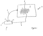
- Figure 1 shows a schematic view of an apparatus 1 for cathodic protection of steel reinforced concrete structures according to the invention.
- the apparatus comprises an electrical source 2, which can be implemented as a voltage or current source.
- the electrical source 2 is provided with at least two output terminals, viz. a first, negative output terminal 3 which is connected with a cathode structure 4 and a second, positive output terminal 5 which is connected with an anode structure 6.
- Figure 1 shows schematically a reinforced concrete structure 7, such as a part of a bridge or another civil engineering construction.
- the structure 7 comprises steel rebars 8 which are at least partially embedded in concrete 9.
- rebars 8 also other steel structures could be used, such as meshes.
- the cathode structure 4 electrically contacts a steel rebar 8, while the anode structure 6 electrically contacts a concrete surface of the reinforced structure 7.
- the electric source 2 During operation, the electric source 2 generates a pulsed electrical current which is fed to the output terminals 3, 5. As a consequence, the pulsed electrical current is impressed to the reinforced concrete structure 7 for protection purposes against corrosion effects.
- the anode structure 4 connected to the positive terminal of the power supply, is chosen to be a relative non-reactive conductor such as carbon or titanium so that its corrosion rate is low.
- the anode reaction then generates oxygen and acid (H + ) as follows: H 2 O ⁇ O 2 + 4H + + 4e -
- the current densities normally encountered in cathode protection systems are sufficiently low for the amount of acid generated to be safely taken up by the normal alkalinity of the concrete.
- the dominant corrosion products in the concrete structure protected by pulse cathodic protection are cotton-ball like goethite, as well as whiskey and delicate iron oxychlorides with a linear dimension of less than 5 ⁇ m.
- a relatively compact and dense substrate composed of high-valent iron oxides hematite, maghemite and magnetite
- iron oxychlorides of lamellar type are formed at 20 ⁇ m scale in the freely corroding concrete, which tend to induce cracking and promote the diffusion of chloride ions.
- the favorable morphology e.g.
- the electrical source is directly current controlled.
- the current is adjusted to a predetermined current curve in dependence of a current measurement of the current that is generated by the electrical source 2.
- the current generated by the electrical source 2 is substantially a periodic block signal with a rise time of approximately 10 mA/10 ⁇ s, or 1000 A/s. It is noted that the driving circuit disclosed in US '405 generates a current pulse with a much lower rise time, as the circuit is voltage controlled. As a consequence, the system disclosed in US '405 does not lead to the combination of counteracted corrosion processes while overprotection is avoided, anyway not in the extend of the apparatus according to the invention.
- the frequency of the block signal is approximately 1 kHz. However, other frequencies could also be applied, e.g. in a range between approximately 100 Hz and approximately 100 kHz, such as 10 kHz. As indicated above, the quality of the rise time of the block signal is important for the desired effect of the apparatus according to the invention.
- Figure 2 shows a graph with current pulse patterns as a function of time which are generated by the current controlled electrical source 2. All pulse patterns shown in Figure 2 are periodic having a frequency of (t 4 - t 0 ) -1 .
- the pattern having a bold line 20 is a pulsed signal with a duty cycle of approximately 50%.
- the pattern having a normal line 21 is a pulsed signal with a duty cycle of approximately 25%.
- the amplitude of the latter signal is approximately twice the amplitude of the first signal, so that the delivered electrical energy per cycle remains substantially the same.
- the pattern having a broken line 22 is a pulsed signal with a duty cycle of approximately 12.5%. Again, the latter signal has an amplitude which is approximately twice the amplitude of the second signal.
- other duty cycles can be employed.
- microstructural investigations have revealed favorable chemical composition and morphologies of the corrosion products and better concrete performance in the case of pulse regime.
- the crystallinity, morphological aspects and spatial distribution of the corrosion and hydration products (characterized by quantitative image analysis on microlevel) provided supporting experimental evidences.
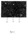
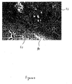
- Figures 3 and 4 shows the difference of the conventional direct current approach ( Figure 3) and the pulsed current approach (Figure 4).
- Figure 3 an interfacial transition zone under prior art conditions is shown as a SEM image with a magnification of 1000 x.
- an enlarged gap, the interfacial transition zone 32 is visible between aggregate 30, such as sand or stone, and cement paste 31.
- the enlarged gap is a side effect of the direct current applied to the concrete structure.
- Figure 4 is also a SEM image with a magnification of 1000 x showing an interfacial transition zone.
- the gap 42 between aggregate 40 and cement paste 43 belongs to a concrete structure that is treated with an apparatus according to the invention. The gap 42 is smaller, thus indicating that the method according to the invention has less side effects than the prior art method.
- anode structure might contact the concrete structure by means of an external electrode e.g. as shown in Figure 1, or by means of an electrode embedded in the concrete structure.
Landscapes
- Chemical & Material Sciences (AREA)
- Engineering & Computer Science (AREA)
- Materials Engineering (AREA)
- Mechanical Engineering (AREA)
- Metallurgy (AREA)
- Organic Chemistry (AREA)
- Prevention Of Electric Corrosion (AREA)
Abstract
Description
- The invention relates to an apparatus for cathodic protection of steel reinforced concrete structures, comprising an electrical source for generating an electrical signal, wherein the electrical source is provided with a first output terminal for connection with a cathode structure for contacting a steel segment of the reinforced concrete structure and with a second output terminal for connection with an anode structure for contacting a concrete surface of the concrete structure.
- Corrosion prevention and protection techniques have been a focus of interest for decades in the field of civil engineering. The corrosion of steel in concrete is essentially an electrochemical process, where at the anode iron is oxidized to iron ions that pass into the pore solution and at the cathode oxygen is reduced to hydroxyl (OH-) ions. Anode and cathode form a short-circuited corrosion cell, with the flow of electrons in the steel and of ions in the pore solution of concrete.
- Cathodic protection has been found to be a proven method and working technique to stop corrosion in reinforced concrete structures. The polarization of the steel reinforcement is achieved by supplying impressed direct current to the steel embedded in concrete structures. The repulsion of aggressive anions (e.g. chloride) which takes place along with the protection itself is a beneficial one as far as the corrosion risk of the steel is concerned.
- The idea of cathodic protection is to artificially shift the potential of a metal so that it becomes either immune or passive. In sacrificial cathode protection, a galvanic cell is set up by connecting the steel to a more reactive metal, usually zinc. The zinc then undergoes the anodic reaction and corrodes whilst the steel is rendered entirely unreactive because the whole surface undergoes the cathodic reaction and that the iron no longer dissolves.
- With impressed direct current cathodic protection, the steel is connected to the negative terminal of an electrical power supply, forcing it to undergo a cathodic reaction. If the potential of the steel is negative enough to make it immune, the cathodic reaction becomes a process whereby water is broken down and hydrogen is liberated as follows:
2H2O + 2e- → H2 + 2OH-
This situation would normally be avoided in concrete since the pH is high and it is possible to re-establish passivity by applying a somewhat less negative potential. This consumes considerably less current and so reduces the cost. The cathode reaction is then
2H2O + O2 + 4e- → 4OH-
and OH- help to maintain the conditions necessary for passivity. - However, the concentrations of alkali ions in the vicinity of the reinforcement will increase as cations will migrate towards the negatively charged steel surface, leading to a variety of side effects. For example, the increased cation concentrations (K+, Ca2+, Mg2+) at the steel-paste interface are reported to cause bond degradation between steel and concrete. So, caution should be bestowed on current densities and protection regimes.
- Moreover, along with ion migration and diffusion due to the cathodic protection current, the heterogeneities and instabilities inherent in the concrete material may lead to non-uniform distribution of the cathodic protection current and thus result in localized overprotected areas. The overprotection current will result in alkali ions accumulation on the steel/rebar interface, thus causing softening of the C-S-H gel, possible alkali silica reaction (ASR) and loss of bond strength. On the other hand, overprotection current will cause increased hydrogen evolution reactions on the steel surface and lead to hydrogen embrittlement in case of prestressed steel reinforcement. Thus, ordinary impressed cathodic protection has been seldom applied to prestressed concrete structures. In addition, cathodic protection current is found to induce structural deformations in the bulk concrete, inducing micro-cracking and unfavorable pore structure alterations.
- In short, main negative effects of cathodic protection comprise bond strength degradation, i.e. loss of adhesion at the steel/concrete interface, coarsening the pore structure and particularly in the interfacial transition zone (ITZ), thus yielding micro-cracks due to the current flow, alkali silica reaction (ASR) or hydrogen embrittlement of pre-stressed steel in concrete structures.
- It is an object of the invention to provide an apparatus for cathodic protection of steel reinforced concrete structures, wherein the disadvantages identified above are reduced. In particular, the invention aims at obtaining an apparatus for cathodic protection of steel reinforced concrete structures, wherein corrosion processes are counteracted while overprotection is avoided. Thereto, according to the invention, the electrical signal is a pulse shaped current and the electrical source is directly current controlled.
- By applying an electrical pulse shaped current, it has surprisingly been found that sufficient polarization of the steel surface is obtained, thus providing conditions in which corrosion is thermodynamically impossible to occur. By delivering roughly 50% of the electrical energy compared with the conventional direct current technique, a substantially equal corrosion protection is obtained, thereby reducing power supply costs. Moreover, the pulse regime achieves sufficient protection while overprotection is avoided and negative side effects are lowered.
- By directly controlling the current of the electrical signal the above-mentioned sides effects of cathodic protection techniques are even further reduced, especially if the rise time of the pulsed current is larger than approximately 100 A/m2s. Preferably, the rise time of the pulsed electrical current is approximately 1000 A/ m2s. However, other values are also applicable, such as 10.000 A/ m2s.
- As an example, the negative side effects on the concrete bulk microstructure and/or on the steel/paste interface are lowered, thus reducing the extent of bond strength degradation that normally accompanies cathodic protection applications. Also negative side effects on the concrete microstructure in terms of less detrimental effects on microstructural properties as porosity, pore size distribution and properties of the interfacial transition zone between paste and aggregate are lowered, the last being of significant importance for the electrolytic path in the system and for the manner of current distribution.
- The research reveals higher effectiveness for the pulse cathodic protection in enhancing the aggressive (chloride) ion migration towards the anode (MMO titanium mesh used) and in reducing the aggressive ion concentration around the cathode (i.e. the steel bar under protection). The pulse technique achieves sufficient steel polarization (≤ -900 mV versus saturated calomel electrode (SCE) for the reinforced concrete) and initial terminal voltage with the same time constant (for the plain concrete) as the steady direct current approach. Moreover, the use of a pulsed electrical signal is found to be less detrimental to the bulk concrete microstructure with respect to porosity, pore connectivity and micro-cracking.
- It is noted that an
American patent publication US 5 324 405 discloses an apparatus for protecting metal structures such as pipelines or well casings in a conductive medium such as the ground. A driving circuit provides a pulsed signal which is voltage controlled. - Further, it is noted that the apparatus according to the invention can be employed not only in the context of maintenance and/or repair of steel reinforced concrete structures, but also in the case of corrosion prevention of such structures. In the latter case, the pulse cathodic protection can be applied in a more economic and less detrimental method compared to conventional impressed direct current techniques.
- As the apparatus according to the invention reduces side effects of cathodic protection techniques, it is also applicable to pre-stressed concrete. Further, it also addresses prevention, improved protection and better performance of reinforced concrete systems in terms of service life and durability issues.
- Advantageously, the electrical pulsed current is periodic and has a duty cycle in the range between approximately 1% and approximately 50%. Preferably, the duty cycle is less than 25%, e.g. 12%. To maintain the desired electrical energy, a decrease of the duty cycle with 50% is compensated by doubling the current, so that the product of the pulse amplitude and the pulse duration remains approximately constant.
- Further, the invention relates to a method.
- Other advantageous embodiments according to the invention are described in the following claims.
- By way of example only, an embodiment of the present invention will now be described with reference to the accompanying figures in which
- Fig. 1 shows a schematic view of an apparatus according to the invention;
- Fig. 2 shows a graph with current pulse patterns;
- Fig. 3 shows a view of an interfacial transition zone under prior art conditions; and
- Fig. 4 shows a view of an interfacial transition zone using the apparatus of Fig. 1.
- The figures are merely schematic views of preferred embodiments according to the invention. In the figures, the same reference numbers refer to equal or corresponding parts.
- Figure 1 shows a schematic view of an
apparatus 1 for cathodic protection of steel reinforced concrete structures according to the invention. The apparatus comprises anelectrical source 2, which can be implemented as a voltage or current source. Theelectrical source 2 is provided with at least two output terminals, viz. a first,negative output terminal 3 which is connected with a cathode structure 4 and a second, positive output terminal 5 which is connected with an anode structure 6. - Further, Figure 1 shows schematically a reinforced
concrete structure 7, such as a part of a bridge or another civil engineering construction. Thestructure 7 comprisessteel rebars 8 which are at least partially embedded inconcrete 9. In stead ofrebars 8 also other steel structures could be used, such as meshes. - The cathode structure 4 electrically contacts a
steel rebar 8, while the anode structure 6 electrically contacts a concrete surface of the reinforcedstructure 7. - During operation, the
electric source 2 generates a pulsed electrical current which is fed to theoutput terminals 3, 5. As a consequence, the pulsed electrical current is impressed to the reinforcedconcrete structure 7 for protection purposes against corrosion effects. - Preferably, the anode structure 4, connected to the positive terminal of the power supply, is chosen to be a relative non-reactive conductor such as carbon or titanium so that its corrosion rate is low. The anode reaction then generates oxygen and acid (H+) as follows:
H2O → O2 + 4H+ + 4e-
The current densities normally encountered in cathode protection systems are sufficiently low for the amount of acid generated to be safely taken up by the normal alkalinity of the concrete. - The dominant corrosion products in the concrete structure protected by pulse cathodic protection are cotton-ball like goethite, as well as whiskey and delicate iron oxychlorides with a linear dimension of less than 5 µm. In addition, a relatively compact and dense substrate composed of high-valent iron oxides (hematite, maghemite and magnetite) are formed in the case of cathodic protection, leading to a more adherent and efficiently protective layer on the steel surface. In contrast, iron oxychlorides of lamellar type are formed at 20 µm scale in the freely corroding concrete, which tend to induce cracking and promote the diffusion of chloride ions. The favorable morphology (e.g. lower crystallinity) of corrosion products in the pulse protected mortars can be attributed to the relatively high pH value and lower salinity (i.e., lower concentration of chloride ions) in the concrete subjected to pulse cathodic protection. The beneficial microstructural alterations result in better corrosion resistance of the protected concretes, and turn out to be the mechanisms underlying the efficiency of pulse cathodic protection techniques.
- Further, the electrical source is directly current controlled. In this process, the current is adjusted to a predetermined current curve in dependence of a current measurement of the current that is generated by the
electrical source 2. By employing an electrical pulsed current there is a favourable charge-discharge cycling, so that ions do not accumulate. This might be a physical cause in favour of the ease of ion migration mechanisms, providing a relatively better performance of the pulse regime with respect to the direct current approach. - The current generated by the
electrical source 2 is substantially a periodic block signal with a rise time of approximately 10 mA/10µs, or 1000 A/s. It is noted that the driving circuit disclosed in US '405 generates a current pulse with a much lower rise time, as the circuit is voltage controlled. As a consequence, the system disclosed in US '405 does not lead to the combination of counteracted corrosion processes while overprotection is avoided, anyway not in the extend of the apparatus according to the invention. Preferably, the frequency of the block signal is approximately 1 kHz. However, other frequencies could also be applied, e.g. in a range between approximately 100 Hz and approximately 100 kHz, such as 10 kHz. As indicated above, the quality of the rise time of the block signal is important for the desired effect of the apparatus according to the invention. - Figure 2 shows a graph with current pulse patterns as a function of time which are generated by the current controlled
electrical source 2. All pulse patterns shown in Figure 2 are periodic having a frequency of (t4 - t0)-1. The pattern having abold line 20 is a pulsed signal with a duty cycle of approximately 50%. Further, the pattern having anormal line 21 is a pulsed signal with a duty cycle of approximately 25%. The amplitude of the latter signal is approximately twice the amplitude of the first signal, so that the delivered electrical energy per cycle remains substantially the same. Then, the pattern having abroken line 22 is a pulsed signal with a duty cycle of approximately 12.5%. Again, the latter signal has an amplitude which is approximately twice the amplitude of the second signal. Obviously, also other duty cycles can be employed. - Moreover, microstructural investigations (SEM, EDAX, XRD) have revealed favorable chemical composition and morphologies of the corrosion products and better concrete performance in the case of pulse regime. The crystallinity, morphological aspects and spatial distribution of the corrosion and hydration products (characterized by quantitative image analysis on microlevel) provided supporting experimental evidences. Chemical analysis, performed for plain and reinforced concrete under various technical conditions, proved the much higher efficiency of the pulse regime in terms of lowering the aggressive ion concentrations in the vicinity of the rebars.
- As an example, Figures 3 and 4 shows the difference of the conventional direct current approach (Figure 3) and the pulsed current approach (Figure 4). In Figure 3 an interfacial transition zone under prior art conditions is shown as a SEM image with a magnification of 1000 x. Obviously, an enlarged gap, the
interfacial transition zone 32, is visible betweenaggregate 30, such as sand or stone, andcement paste 31. The enlarged gap is a side effect of the direct current applied to the concrete structure. Figure 4 is also a SEM image with a magnification of 1000 x showing an interfacial transition zone. However the zone shown in Figure 4, thegap 42 between aggregate 40 andcement paste 43, belongs to a concrete structure that is treated with an apparatus according to the invention. Thegap 42 is smaller, thus indicating that the method according to the invention has less side effects than the prior art method. - The invention is not restricted to the embodiments described herein. It will be understood that many variants are possible. Instead of employing a single pair of electrodes, also a multiple set of electrodes of either the cathode structure or the anode structure, or both, could be used.
- Further, the anode structure might contact the concrete structure by means of an external electrode e.g. as shown in Figure 1, or by means of an electrode embedded in the concrete structure.
- Other such variants will be obvious for the person skilled in the art and are considered to lie within the scope of the invention as formulated in the following claims.
Claims (6)
- An apparatus for cathodic protection of steel reinforced concrete structures, comprising an electrical source for generating an electrical signal, wherein the electrical source is provided with a first output terminal for connection with a cathode structure for contacting a steel segment of the reinforced concrete structure and with a second output terminal for connection with an anode structure for contacting a concrete surface of the concrete structure, wherein the electrical signal is a pulse shaped current and wherein the electrical source is directly current controlled.
- An apparatus according to claim 1, wherein the rise time of the pulsed current is larger than approximately 100 A/m2s.
- An apparatus according to claim 1 or 2, wherein the pulsed current is substantially a periodic block signal.
- An apparatus according to any previous claim, wherein the frequency of the pulsed current is in a range between approximately 100 Hz and approximately 100 kHz.
- An apparatus according to any previous claim, wherein the duty cycle of the pulsed current is in the range between approximately 1% and approximately 50%.
- A method for cathodic protection of steel reinforced concrete structures, comprising the steps of:- contacting a steel segment of the concrete structure by means of a cathode structure;- contacting a concrete surface of the concrete structure by means of an anode structure;- connecting the cathode structure and the anode structure with a first and a second output terminal, respectively, of an electrical source for generating an electrical signal;- driving the electrical source to generate a pulsed electrical signal; and- directly controlling the current of the electrical signal.
Priority Applications (1)
| Application Number | Priority Date | Filing Date | Title |
|---|---|---|---|
| EP05077395A EP1777322A1 (en) | 2005-10-18 | 2005-10-18 | Apparatus for cathodic protection of steel reinforced concrete structures and method |
Applications Claiming Priority (1)
| Application Number | Priority Date | Filing Date | Title |
|---|---|---|---|
| EP05077395A EP1777322A1 (en) | 2005-10-18 | 2005-10-18 | Apparatus for cathodic protection of steel reinforced concrete structures and method |
Publications (1)
| Publication Number | Publication Date |
|---|---|
| EP1777322A1 true EP1777322A1 (en) | 2007-04-25 |
Family
ID=35945135
Family Applications (1)
| Application Number | Title | Priority Date | Filing Date |
|---|---|---|---|
| EP05077395A Withdrawn EP1777322A1 (en) | 2005-10-18 | 2005-10-18 | Apparatus for cathodic protection of steel reinforced concrete structures and method |
Country Status (1)
| Country | Link |
|---|---|
| EP (1) | EP1777322A1 (en) |
Cited By (4)
| Publication number | Priority date | Publication date | Assignee | Title |
|---|---|---|---|---|
| US9353446B2 (en) | 2013-04-29 | 2016-05-31 | Transistor Devices, Inc. | Systems and methods for impressed current cathodic protection |
| CN110333316A (en) * | 2019-07-16 | 2019-10-15 | 吴云 | One kind is for judging gather materials containing the slate active concrete microtrabeculae test specimen of alkali_silica reaction and its preparation and application |
| CN110376328A (en) * | 2019-07-16 | 2019-10-25 | 吴云 | It is a kind of to judge the active method of alkali_silica reaction of gathering materials containing slate |
| CN117805156A (en) * | 2024-02-27 | 2024-04-02 | 太原理工大学 | Test method for the degree of hydration in the interface transition zone between the repair material and the substrate |
Citations (8)
| Publication number | Priority date | Publication date | Assignee | Title |
|---|---|---|---|---|
| US3242064A (en) * | 1960-02-29 | 1966-03-22 | Engelhard Ind Inc | Cathodic protection system |
| EP0448963A1 (en) * | 1990-02-26 | 1991-10-02 | Nuova Polmet Cathodic Protection S.R.L. | Control and automatic regulation device for cathodic protection systems in reinforced concrete structures |
| WO1992011399A1 (en) * | 1990-12-18 | 1992-07-09 | Coating A.S. | Method of repairing building constructions with metal parts embedded in them |
| US5324405A (en) * | 1991-09-09 | 1994-06-28 | Doniguian Thaddeus M | Pulse cathodic protection system |
| EP1063321A2 (en) * | 1999-06-17 | 2000-12-27 | Gronvold & Karnov AS | Improvements in cathodic protection for concrete and masonry structures |
| DE10001706A1 (en) * | 2000-01-18 | 2001-08-02 | Citec Gmbh | Combination electrode for the restoration of corrosion-damaged reinforced concrete includes an electrode, a reusable electrolyte reservoir, a reference electrode, a humidifier and a measuring system |
| EP1241280A1 (en) * | 2001-03-12 | 2002-09-18 | Cebelcor A.S.B.L. | Process and apparatus for the cathodic protection of a metal structure |
| US20030173231A1 (en) * | 1999-09-15 | 2003-09-18 | Ulrich Schneck | Combination electrode for electrochemical restoration of corrosion-damaged reinforced concrete and method of controlling same |
-
2005
- 2005-10-18 EP EP05077395A patent/EP1777322A1/en not_active Withdrawn
Patent Citations (8)
| Publication number | Priority date | Publication date | Assignee | Title |
|---|---|---|---|---|
| US3242064A (en) * | 1960-02-29 | 1966-03-22 | Engelhard Ind Inc | Cathodic protection system |
| EP0448963A1 (en) * | 1990-02-26 | 1991-10-02 | Nuova Polmet Cathodic Protection S.R.L. | Control and automatic regulation device for cathodic protection systems in reinforced concrete structures |
| WO1992011399A1 (en) * | 1990-12-18 | 1992-07-09 | Coating A.S. | Method of repairing building constructions with metal parts embedded in them |
| US5324405A (en) * | 1991-09-09 | 1994-06-28 | Doniguian Thaddeus M | Pulse cathodic protection system |
| EP1063321A2 (en) * | 1999-06-17 | 2000-12-27 | Gronvold & Karnov AS | Improvements in cathodic protection for concrete and masonry structures |
| US20030173231A1 (en) * | 1999-09-15 | 2003-09-18 | Ulrich Schneck | Combination electrode for electrochemical restoration of corrosion-damaged reinforced concrete and method of controlling same |
| DE10001706A1 (en) * | 2000-01-18 | 2001-08-02 | Citec Gmbh | Combination electrode for the restoration of corrosion-damaged reinforced concrete includes an electrode, a reusable electrolyte reservoir, a reference electrode, a humidifier and a measuring system |
| EP1241280A1 (en) * | 2001-03-12 | 2002-09-18 | Cebelcor A.S.B.L. | Process and apparatus for the cathodic protection of a metal structure |
Cited By (5)
| Publication number | Priority date | Publication date | Assignee | Title |
|---|---|---|---|---|
| US9353446B2 (en) | 2013-04-29 | 2016-05-31 | Transistor Devices, Inc. | Systems and methods for impressed current cathodic protection |
| CN110333316A (en) * | 2019-07-16 | 2019-10-15 | 吴云 | One kind is for judging gather materials containing the slate active concrete microtrabeculae test specimen of alkali_silica reaction and its preparation and application |
| CN110376328A (en) * | 2019-07-16 | 2019-10-25 | 吴云 | It is a kind of to judge the active method of alkali_silica reaction of gathering materials containing slate |
| CN117805156A (en) * | 2024-02-27 | 2024-04-02 | 太原理工大学 | Test method for the degree of hydration in the interface transition zone between the repair material and the substrate |
| CN117805156B (en) * | 2024-02-27 | 2024-05-10 | 太原理工大学 | Method for testing hydration degree of interface transition zone between repair material and base material |
Similar Documents
| Publication | Publication Date | Title |
|---|---|---|
| CN101142341B (en) | Concrete Treatment Methods | |
| CZ20031118A3 (en) | Concrete structure with double protected reinforcing elements | |
| SK5692003A3 (en) | Cathodic protection of steel in reinforced concrete with electroosmotic treatment | |
| US5366670A (en) | Method of imparting corrosion resistance to reinforcing steel in concrete structures | |
| EP1777322A1 (en) | Apparatus for cathodic protection of steel reinforced concrete structures and method | |
| KR101081991B1 (en) | Artificial crack healing method for concrete using electrochemical deposition | |
| DK2722418T3 (en) | TREATMENT PROCESS FOR CONCRETE | |
| IL104837A (en) | Method for electrochemical treatment of reinforcing steel in concrete having embedded steel reinforcement | |
| US6322691B1 (en) | Method for passivating steel in large structures formed of steel-reinforced concrete | |
| EA004161B1 (en) | Cathodic protection of reinforced concrete with impregnated corrosion inhibitor | |
| Benito et al. | Corrosion damage measurement on reinforced concrete by impressed voltage technique and gravimetric method | |
| KR102088847B1 (en) | Method of reducing scale of cathode for electrolysis of ballast water | |
| KR20130045484A (en) | Intermittent cathodic protection method for concrete structure, intermittent cathodic protection system for concrete structure and intermittent cathodic protection system for nuclear structure | |
| JP2649090B2 (en) | Desalination method for RC / SRC structure | |
| JP2649089B2 (en) | Desalination method for RC / SRC structure | |
| JP2003064489A (en) | Corrosion protection method for reinforced concrete | |
| CN103821382B (en) | A kind of electric osmose of rehabilitating concrete structure chlorine salt corrosion substitutes hole solution method | |
| Costa | Corrosion of steel reinforcing in concrete and masonry structures | |
| JP3906110B2 (en) | Electrolysis equipment | |
| KR100290641B1 (en) | Apparatus for removing iron oxide layer on surface of hot rolled steel sheet using unidirectional pulsed electrolysis | |
| JP2024007856A (en) | ASR suppression method for existing reinforced concrete structures | |
| HK1169841B (en) | Treatment process for concrete | |
| AU6509694A (en) | Method for treating reinforced concrete and/or the reinforcement thereof | |
| HK1110100B (en) | Treatment process for concrete | |
| Taylor | ELECTROCHEMICAL SYSTEMS FOR REPAIR OF REINFORCED CONCRETE STRUCTURES |
Legal Events
| Date | Code | Title | Description |
|---|---|---|---|
| PUAI | Public reference made under article 153(3) epc to a published international application that has entered the european phase |
Free format text: ORIGINAL CODE: 0009012 |
|
| AK | Designated contracting states |
Kind code of ref document: A1 Designated state(s): AT BE BG CH CY CZ DE DK EE ES FI FR GB GR HU IE IS IT LI LT LU LV MC NL PL PT RO SE SI SK TR |
|
| AX | Request for extension of the european patent |
Extension state: AL BA HR MK YU |
|
| 17P | Request for examination filed |
Effective date: 20071016 |
|
| AKX | Designation fees paid |
Designated state(s): AT BE BG CH CY CZ DE DK EE ES FI FR GB GR HU IE IS IT LI LT LU LV MC NL PL PT RO SE SI SK TR |
|
| 17Q | First examination report despatched |
Effective date: 20071227 |
|
| RAP1 | Party data changed (applicant data changed or rights of an application transferred) |
Owner name: VAN DER HEIDE CATHODIC PROTECTION & CORROSION ENGI |
|
| STAA | Information on the status of an ep patent application or granted ep patent |
Free format text: STATUS: THE APPLICATION IS DEEMED TO BE WITHDRAWN |
|
| 18D | Application deemed to be withdrawn |
Effective date: 20110127 |