EP1777084B1 - Multi function coupling - Google Patents
Multi function coupling Download PDFInfo
- Publication number
- EP1777084B1 EP1777084B1 EP05109361A EP05109361A EP1777084B1 EP 1777084 B1 EP1777084 B1 EP 1777084B1 EP 05109361 A EP05109361 A EP 05109361A EP 05109361 A EP05109361 A EP 05109361A EP 1777084 B1 EP1777084 B1 EP 1777084B1
- Authority
- EP
- European Patent Office
- Prior art keywords
- coupling
- trailer
- end part
- locking
- coupling end
- Prior art date
- Legal status (The legal status is an assumption and is not a legal conclusion. Google has not performed a legal analysis and makes no representation as to the accuracy of the status listed.)
- Expired - Lifetime
Links
Images



Classifications
-
- B—PERFORMING OPERATIONS; TRANSPORTING
- B60—VEHICLES IN GENERAL
- B60D—VEHICLE CONNECTIONS
- B60D1/00—Traction couplings; Hitches; Draw-gear; Towing devices
-
- B—PERFORMING OPERATIONS; TRANSPORTING
- B60—VEHICLES IN GENERAL
- B60P—VEHICLES ADAPTED FOR LOAD TRANSPORTATION OR TO TRANSPORT, TO CARRY, OR TO COMPRISE SPECIAL LOADS OR OBJECTS
- B60P1/00—Vehicles predominantly for transporting loads and modified to facilitate loading, consolidating the load, or unloading
- B60P1/36—Vehicles predominantly for transporting loads and modified to facilitate loading, consolidating the load, or unloading using endless chains or belts thereon
- B60P1/365—Vehicles predominantly for transporting loads and modified to facilitate loading, consolidating the load, or unloading using endless chains or belts thereon the chains or belts being fixed to a rigid pusher plate
Definitions
- the present invention relates to a trailer coupling for connecting a traction vehicle to a trailer, to be pulled in a pulling direction by said vehicle.
- the trailer coupling comprises a coupling part mounted at the back of the vehicle being adapted to receive a coupling end part of a drawbar fixed to the trailer by relative movement of the coupling part and the coupling end part in a receiving direction.
- the coupling end part is connected to the drawbar via a joint.
- a vehicle is connected manually to a trailer. This connection is carried out after the vehicle has been positioned in relation to the trailer.
- the drawbar of the trailer is provided with a hole, in which a cylinder from the coupling part is mounted for mechanical connection.
- such handling is time-consuming and detrimental to the operator.
- EP-A-1 398185 discloses a tow coupling with a coupling jaw and a clutch body, which may be inserted into the coupling jaw.
- the clutch body is provided with a coupling cone with a circumferential breech nut for insertion or retraction of the radially adjustable locking segments surrounding the coupling cone.
- One object of the present invention is to provide an automatic coupling for a vehicle and a trailer, that in relation to prior art coupling systems, provides a coupling with improved characteristics.
- Another object of the present invention is to provide a coupling which is easy to handle and provides a safe connection for the trailer.
- Further object of the present invention is to provide increased personal safety, hence the driver does not need to leave the truck and enter the roadway during connection.
- a trailer coupling for connecting a traction vehicle to a trailer, to be pulled in a pulling direction by said vehicle.
- the coupling comprises a coupling part mounted at the back of the vehicle being adapted to receive a coupling end part of a drawbar fixed to the trailer by relative movement of the coupling part and the coupling end part in a receiving direction.
- the coupling end part is connected to the drawbar via a joint.
- a locking part is arranged to engage with the outer geometry of said coupling end part, so as to secure the mechanical connection of the vehicle to the trailer. It is advantageous to engage the locking part at the geometry/perimeter of the coupling end part from a construction point of view.
- the locking part has a wedge surface formed to force the coupling end part further into the coupling part during activation of said locking part.
- a wedge can maintain the locking function independent of wear to surfaces and remain slack free. It is further possible to provide a gear ratio to increase the engaging force due to the angle of the wedge surface. The use of wedge surfaces make it possible to compensate for wear, and it is possible to achieve less play.
- the coupling end part is provided with a recess in the outer geometry having a wedge surface for interaction with said wedge surface of the locking part.
- a recess is that it does not have any protruding parts that could interfere during the engagement between the coupling part and the coupling end part.
- the recess can further be performed with large contact surfaces for the wedge surface which is advantageous from a wear point of view.
- the locking part is movable mainly in a direction normal/perpendicular to said pulling direction for locking of said coupling end part.
- a locking movement in the normal direction to the pulling direction will provide an effective locking of the coupling.
- the wedges can operate vertical as well as horizontal or in an inclined direction. It is possible to use one locking part or more, if two wedges are used they can operate either in the same direction or in opposite directions.
- Preferably two locking parts are symmetrically located for locking of the coupling end part. It is further advantageous to provide two, from each other independent, locking parts since a redundant system is achieved.
- an operable blocking means as an safety lock pin, is provided for blocking the locking parts in locked position.
- a blocking means can be used to block the wedge in locked position, by moving the safety lock pin perpendicular to the movement of the wedge.
- the coupling end part is tapered, in the receiving direction, for guiding said coupling end part both in horizontal and vertical direction during connection.
- a tapered geometry increases the possibility to guide the coupling during connection.
- an openable cover means is provided for covering an engagement opening of said coupling part to reduce the risk of dirt and moisture to penetrate through said opening. Further the cover means, in open position, provides a surface for guiding the coupling end part to engagement with said coupling part.
- the guiding surface of the cover means, in open position, is sloping in direction towards the opening of said coupling part.
- the trailer coupling 1 comprises a coupling part 2 which is adapted to be attached to a drawbeam of a traction vehicle (not shown), and a coupling end part 3 which has a main tapered portion and a rear portion, which is arranged via a joint 7 in a drawbar of a trailer (not shown).
- the rear portion of the coupling end part 3 is turnable in the joint 7, and the entire drawbar being pivotally arranged at the trailer, the coupling end part 3 is positionable in an arbitrary position.
- the coupling part 2 has a catching mouth with a receiving space which is adapted to receive the coupling end part 3.
- the main portion of the coupling end part 3 is wedge-shaped in the horizontal plane.
- wedge-shape is in the first place meant an essentially triangular shape of the kind as shown in the figures, but it should be noted that the main portion could also be of any other tapered shape.
- the main portion is preferably at least partially hollow.
- the coupling end part 3 is further provided with a recess on each side in the front outer geometry/perimeter.
- the recess forms a wedge surface for locking and pulling of the coupling end part 3 into connection with the coupling part 2.
- the wedge surface has an orientation with the normal direction essentially in the pulling direction to provide a proper connection force for the coupling.
- Fig 2a-b shows how the cover means 6 is operated between a closed position ( fig 2a ), preventing dirt and moisture from penetrating into the inner portion of the coupling part.
- the cover means 6 is operated to an open position by an power source.
- the cover means will, in the open position, function as a guide for the coupling end part when entering into the coupling part, since it is sloping in direction towards the opening of said coupling part 2.
- the coupling part Before a connection between vehicle and trailer is started the coupling part is prepared for connection. As shown in fig 3a the cover means is opened and the locking wedges 4 are in an open position, ready to receive the coupling end part.
- Fig 3b shows how he coupling end part 3 is inserted into the catching mouth of the coupling part 2, the locking wedges 4 are engaging the coupling end part and the wedge surface 9 of the locking wedge 4 comes in sliding contact with the wedge surface of the recess in the coupling end part.
- the locking wedges are operated by a power source for example an electric motor, pneumatic or hydraulic cylinder.
- Fig 3c shows how the coupling end part 3 is forced into tight contact with the coupling part by moving the locking wedges 4 downwards to engagement between the wedge surfaces.
- the sliding interaction provides a gear ratio for the locking wedges 4 during connection of the coupling. Consequently the trailer is mechanically secured to the traction vehicle. If there is tolerances or mechanical wear associated with the components for the locking wedge it is possible, with the design according to the invention, to avoid play since the wedge can be moved further until a tight connection of the coupling is achieved.
- the angle between the operational movement of the locking wedge 4 and the contact wedge surfaces provides a gear ratio for amplification of the operation force to a connecting force.
- the safety blocking means 5 shown in fig 3d can be used to block the locking wedges 4 in the locked position if the locking wedge 4 is not self-locking.
- the blocking means 5 will prevent the coupling from unintentional loosening of the locking wedge 4, for example by vibrations or rattle.
- To provide a safe operation of the blocking means 5 it is performed as a safety lock pin, which is spring loaded towards the blocking position and has to be actively maneuvered, e.g. by pneumatic or hydraulic acting actuators, for release from the blocking position. It is of course possible to use other kind of components for the operation of the blocking means 5.
Landscapes
- Engineering & Computer Science (AREA)
- Transportation (AREA)
- Mechanical Engineering (AREA)
- Mechanical Operated Clutches (AREA)
- Connection Of Plates (AREA)
- Mutual Connection Of Rods And Tubes (AREA)
- Nitrogen Condensed Heterocyclic Rings (AREA)
- Optical Communication System (AREA)
- Graft Or Block Polymers (AREA)
- Vehicle Cleaning, Maintenance, Repair, Refitting, And Outriggers (AREA)
Abstract
Description
- The present invention relates to a trailer coupling for connecting a traction vehicle to a trailer, to be pulled in a pulling direction by said vehicle. The trailer coupling comprises a coupling part mounted at the back of the vehicle being adapted to receive a coupling end part of a drawbar fixed to the trailer by relative movement of the coupling part and the coupling end part in a receiving direction. The coupling end part is connected to the drawbar via a joint.
- Traditionally, a vehicle is connected manually to a trailer. This connection is carried out after the vehicle has been positioned in relation to the trailer. Usually, the drawbar of the trailer is provided with a hole, in which a cylinder from the coupling part is mounted for mechanical connection. However, such handling is time-consuming and detrimental to the operator.
- Drawbacks with prior art couplings are that they are not user friendly positioned regarding to mechanical, hydraulic, pneumatic and electrical couplings, there is also the risk for wrong handling due to the human factor. Further there is ergonomic problems and personal injury.
-
EP-A-1 398185 discloses a tow coupling with a coupling jaw and a clutch body, which may be inserted into the coupling jaw. The clutch body is provided with a coupling cone with a circumferential breech nut for insertion or retraction of the radially adjustable locking segments surrounding the coupling cone. - One object of the present invention is to provide an automatic coupling for a vehicle and a trailer, that in relation to prior art coupling systems, provides a coupling with improved characteristics.
- Another object of the present invention is to provide a coupling which is easy to handle and provides a safe connection for the trailer.
- Further object of the present invention is to provide increased personal safety, hence the driver does not need to leave the truck and enter the roadway during connection.
- At least one of the above mentioned object is achieved by a trailer coupling for connecting a traction vehicle to a trailer, to be pulled in a pulling direction by said vehicle. The coupling comprises a coupling part mounted at the back of the vehicle being adapted to receive a coupling end part of a drawbar fixed to the trailer by relative movement of the coupling part and the coupling end part in a receiving direction. The coupling end part is connected to the drawbar via a joint. A locking part is arranged to engage with the outer geometry of said coupling end part, so as to secure the mechanical connection of the vehicle to the trailer. It is advantageous to engage the locking part at the geometry/perimeter of the coupling end part from a construction point of view.
- The locking part has a wedge surface formed to force the coupling end part further into the coupling part during activation of said locking part. A wedge can maintain the locking function independent of wear to surfaces and remain slack free. It is further possible to provide a gear ratio to increase the engaging force due to the angle of the wedge surface. The use of wedge surfaces make it possible to compensate for wear, and it is possible to achieve less play.
- The coupling end part is provided with a recess in the outer geometry having a wedge surface for interaction with said wedge surface of the locking part. One advantage with a recess is that it does not have any protruding parts that could interfere during the engagement between the coupling part and the coupling end part. The recess can further be performed with large contact surfaces for the wedge surface which is advantageous from a wear point of view.
- Advantageously the locking part is movable mainly in a direction normal/perpendicular to said pulling direction for locking of said coupling end part. A locking movement in the normal direction to the pulling direction will provide an effective locking of the coupling. The wedges can operate vertical as well as horizontal or in an inclined direction. It is possible to use one locking part or more, if two wedges are used they can operate either in the same direction or in opposite directions. Preferably two locking parts are symmetrically located for locking of the coupling end part. It is further advantageous to provide two, from each other independent, locking parts since a redundant system is achieved.
- Advantageously an operable blocking means, as an safety lock pin, is provided for blocking the locking parts in locked position. To provide a reliable and safe connection between vehicle and trailer a blocking means can be used to block the wedge in locked position, by moving the safety lock pin perpendicular to the movement of the wedge.
- According to the inventive concept the coupling end part is tapered, in the receiving direction, for guiding said coupling end part both in horizontal and vertical direction during connection. A tapered geometry increases the possibility to guide the coupling during connection.
- Preferably an openable cover means is provided for covering an engagement opening of said coupling part to reduce the risk of dirt and moisture to penetrate through said opening. Further the cover means, in open position, provides a surface for guiding the coupling end part to engagement with said coupling part.
- Advantageously the guiding surface of the cover means, in open position, is sloping in direction towards the opening of said coupling part.
- By way of example, embodiments of the present invention will now be described with reference to the accompanying figures of drawings in which;
-
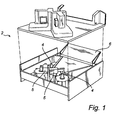
Fig 1 is a perspective view of partly exploded coupling part. -
Fig 2a shows in a side view the cover means in closed position. -
Fig 2b shows in a side view how the cover means is opened. -
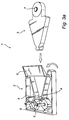
Fig 3a is a perspective view showing the coupling end part being connected with the coupling part. -
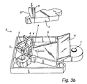
Fig 3b is a perspective view of the coupling part connected with the coupling end part in detail. -
Fig 3c is a perspective view of the coupling showing the engagement of the locking wedge. -
Fig 3d is a perspective view of the coupling showing the activation of the blocking means. - One embodiment of the trailer coupling, according to the invention, will now be described in relation to the figures. The trailer coupling 1 according to the present invention comprises a
coupling part 2 which is adapted to be attached to a drawbeam of a traction vehicle (not shown), and acoupling end part 3 which has a main tapered portion and a rear portion, which is arranged via ajoint 7 in a drawbar of a trailer (not shown). The rear portion of thecoupling end part 3 is turnable in thejoint 7, and the entire drawbar being pivotally arranged at the trailer, thecoupling end part 3 is positionable in an arbitrary position. Thecoupling part 2 has a catching mouth with a receiving space which is adapted to receive thecoupling end part 3. - The main portion of the
coupling end part 3 is wedge-shaped in the horizontal plane. By wedge-shape is in the first place meant an essentially triangular shape of the kind as shown in the figures, but it should be noted that the main portion could also be of any other tapered shape. The main portion is preferably at least partially hollow. Thecoupling end part 3 is further provided with a recess on each side in the front outer geometry/perimeter. The recess forms a wedge surface for locking and pulling of thecoupling end part 3 into connection with thecoupling part 2. The wedge surface has an orientation with the normal direction essentially in the pulling direction to provide a proper connection force for the coupling. -
Fig 2a-b shows how the cover means 6 is operated between a closed position (fig 2a ), preventing dirt and moisture from penetrating into the inner portion of the coupling part. Infig 2b the cover means 6 is operated to an open position by an power source. The cover means will, in the open position, function as a guide for the coupling end part when entering into the coupling part, since it is sloping in direction towards the opening of saidcoupling part 2. - Before a connection between vehicle and trailer is started the coupling part is prepared for connection. As shown in
fig 3a the cover means is opened and the lockingwedges 4 are in an open position, ready to receive the coupling end part.Fig 3b shows how he couplingend part 3 is inserted into the catching mouth of thecoupling part 2, the lockingwedges 4 are engaging the coupling end part and the wedge surface 9 of the lockingwedge 4 comes in sliding contact with the wedge surface of the recess in the coupling end part. The locking wedges are operated by a power source for example an electric motor, pneumatic or hydraulic cylinder.Fig 3c shows how thecoupling end part 3 is forced into tight contact with the coupling part by moving the lockingwedges 4 downwards to engagement between the wedge surfaces. The sliding interaction provides a gear ratio for the lockingwedges 4 during connection of the coupling. Consequently the trailer is mechanically secured to the traction vehicle. If there is tolerances or mechanical wear associated with the components for the locking wedge it is possible, with the design according to the invention, to avoid play since the wedge can be moved further until a tight connection of the coupling is achieved. - The angle between the operational movement of the locking
wedge 4 and the contact wedge surfaces provides a gear ratio for amplification of the operation force to a connecting force. The safety blocking means 5 shown infig 3d can be used to block the lockingwedges 4 in the locked position if the lockingwedge 4 is not self-locking. The blocking means 5 will prevent the coupling from unintentional loosening of the lockingwedge 4, for example by vibrations or rattle. To provide a safe operation of the blocking means 5 it is performed as a safety lock pin, which is spring loaded towards the blocking position and has to be actively maneuvered, e.g. by pneumatic or hydraulic acting actuators, for release from the blocking position. It is of course possible to use other kind of components for the operation of the blocking means 5. - In this manner it is possible to achieve a proper and safe connection of the trailer.
- It will be appreciated that the embodiment described above can be modified and varied by a person skilled in the art without departing from the inventive concept defined in the claims. For example the coupling can be designed in a different way, as long as the locking wedge engages in the outer geometry.
Claims (10)
- A trailer coupling (1) for connecting a traction vehicle to a trailer, to be pulled in a pulling direction by said vehicle, comprising a coupling part (2) mounted at the back of the vehicle being adapted to receive a coupling end part (3) of a drawbar fixed to the trailer by relative movement of the coupling part (2) and the coupling end part (3) in a receiving direction, said coupling end part (3) being connected to the drawbar via a joint (7) wherein
the coupling end part is wedge-shaped in the horizontal plane, and is provided with a recess in its outer geometry, said recess having a wedge surface, and
wherein
the coupling further comprises a locking part (4) arranged to engage with said recess, so as to secure the mechanical connection of the vehicle to the trailer
characterized in that said locking part (4) having a wedge surface formed to interact with said wedge surface of said recess to force the coupling end part (3) further into the coupling part (2) during activation of said locking part. - A trailer coupling (1) according to claim 1, wherein said locking part (4) is movable mainly in a direction normal to said pulling direction for locking of said coupling end part (3).
- A trailer coupling (1) according to any of the preceding claims, wherein an operable blocking means (5) is provided for blocking the locking part (4) in locked position.
- A trailer coupling (1) according to any of the preceding claims, wherein two locking parts (4) are symmetrically located for locking of the coupling end part (3).
- A trailer coupling according to claim 4, wherein said locking parts (4) are arranged on either side of a central axis of said coupling end.
- A trailer coupling according to claim 4, wherein said locking parts are movable along parallel displaced paths.
- A trailer coupling (1) according to any of the preceding claims, wherein the coupling end part is tapered, in the receiving direction, for guiding said coupling end part both in horizontal and vertical direction during connection.
- A trailer coupling (1) according to any of the preceding claims, wherein an openable cover means (6) is provided for covering an engagement opening of said coupling part (2) to reduce the risk of dirt and moisture to penetrate through said opening.
- A trailer coupling (1) according to claim 8, wherein said cover means (6), in open position, provides a surface for guiding the coupling end part (3) to engagement with said coupling part (2).
- A trailer coupling (1) according to claim 9, wherein said guiding surface of the cover means (6), in open position, is sloping in direction towards the opening of said coupling part (2).
Priority Applications (5)
| Application Number | Priority Date | Filing Date | Title |
|---|---|---|---|
| EP05109361A EP1777084B1 (en) | 2005-10-07 | 2005-10-07 | Multi function coupling |
| DE602005011300T DE602005011300D1 (en) | 2005-10-07 | 2005-10-07 | Multifunction coupling |
| AT05109361T ATE415297T1 (en) | 2005-10-07 | 2005-10-07 | MULTIFUNCTIONAL CLUTCH |
| ES05109361T ES2317156T3 (en) | 2005-10-07 | 2005-10-07 | MULTIFUNCTIONAL COUPLING. |
| DK05109361T DK1777084T3 (en) | 2005-10-07 | 2005-10-07 | multifunction Clutch |
Applications Claiming Priority (1)
| Application Number | Priority Date | Filing Date | Title |
|---|---|---|---|
| EP05109361A EP1777084B1 (en) | 2005-10-07 | 2005-10-07 | Multi function coupling |
Publications (2)
| Publication Number | Publication Date |
|---|---|
| EP1777084A1 EP1777084A1 (en) | 2007-04-25 |
| EP1777084B1 true EP1777084B1 (en) | 2008-11-26 |
Family
ID=35759241
Family Applications (1)
| Application Number | Title | Priority Date | Filing Date |
|---|---|---|---|
| EP05109361A Expired - Lifetime EP1777084B1 (en) | 2005-10-07 | 2005-10-07 | Multi function coupling |
Country Status (5)
| Country | Link |
|---|---|
| EP (1) | EP1777084B1 (en) |
| AT (1) | ATE415297T1 (en) |
| DE (1) | DE602005011300D1 (en) |
| DK (1) | DK1777084T3 (en) |
| ES (1) | ES2317156T3 (en) |
Families Citing this family (2)
| Publication number | Priority date | Publication date | Assignee | Title |
|---|---|---|---|---|
| US8505949B2 (en) | 2009-04-10 | 2013-08-13 | Saf-Holland, Inc. | Automatic pneumatic/electrical coupler system for tractor-trailer combination vehicles |
| FR2951404B1 (en) * | 2009-10-20 | 2012-10-12 | New York Finance Et Innovation N Y F I | DEVICE FOR AUTOMATICALLY HANGING AND LOCKING A HITCH BETWEEN A TRACTOR VEHICLE AND A TRACT ROAD VEHICLE |
Family Cites Families (8)
| Publication number | Priority date | Publication date | Assignee | Title |
|---|---|---|---|---|
| US1379874A (en) * | 1921-04-13 | 1921-05-31 | John K Miller | Tractor-hitch |
| FR605009A (en) * | 1925-10-24 | 1926-05-18 | Gustave Carde & Fils Sa | Device for automatic coupling of vehicles to a tractor |
| GB1434093A (en) * | 1972-05-05 | 1976-04-28 | Maschf Augsburg Nuernberg Ag | Couplings |
| US4349211A (en) * | 1979-01-22 | 1982-09-14 | Cooper George N | Bumper hitch |
| DE9409992U1 (en) * | 1993-08-07 | 1994-10-27 | Scharfenbergkupplung Gmbh, 38239 Salzgitter | Automatic rod coupling |
| US6908096B2 (en) * | 2002-09-06 | 2005-06-21 | Uara Services, Inc. | Cover, including hinged door, for trailer hitch receivers of multiple sizes and methods |
| EP1398185B1 (en) | 2002-09-10 | 2006-11-15 | GKN Walterscheid Cramer GmbH | Trailer coupling |
| DE10258065A1 (en) * | 2002-12-11 | 2004-06-24 | Cramer Kupplung Gmbh & Co. Kg | Trailer coupling for tractor-trailer vehicle combination has supply line couplings closed upon assembly of cone coupling and coupling seat |
-
2005
- 2005-10-07 DE DE602005011300T patent/DE602005011300D1/en not_active Expired - Lifetime
- 2005-10-07 EP EP05109361A patent/EP1777084B1/en not_active Expired - Lifetime
- 2005-10-07 ES ES05109361T patent/ES2317156T3/en not_active Expired - Lifetime
- 2005-10-07 AT AT05109361T patent/ATE415297T1/en not_active IP Right Cessation
- 2005-10-07 DK DK05109361T patent/DK1777084T3/en active
Also Published As
| Publication number | Publication date |
|---|---|
| DK1777084T3 (en) | 2009-03-23 |
| ATE415297T1 (en) | 2008-12-15 |
| EP1777084A1 (en) | 2007-04-25 |
| ES2317156T3 (en) | 2009-04-16 |
| DE602005011300D1 (en) | 2009-01-08 |
Similar Documents
| Publication | Publication Date | Title |
|---|---|---|
| CA2779368C (en) | A quick hitch coupler | |
| CA2413766C (en) | New and improved trailer coupler | |
| US5906387A (en) | Retractable hitch for a gooseneck trailer | |
| CA2796370C (en) | Trailer tongue connection unit | |
| US6193261B1 (en) | Quick release hitch pin | |
| US7722073B2 (en) | Trailer coupler | |
| US5303790A (en) | Quick attaching power take off | |
| AU2001271752A1 (en) | New and improved trailer coupler | |
| US20190225036A1 (en) | Pivotal tow bar assembly | |
| US4738126A (en) | Releasable locking device | |
| KR102911356B1 (en) | A device for joining two shafts, and a hitching device provided with the joining device | |
| EP1777084A1 (en) | Multi function coupling | |
| JPH0555349B2 (en) | ||
| US4258930A (en) | Hitching device with safety lock | |
| EP3533690B1 (en) | Retractable pull handle assemblies for fifth wheels | |
| US7461856B2 (en) | Trailer coupler | |
| US20080211216A1 (en) | Coupler for a Vehicle Accessory | |
| DE102022123784B4 (en) | Trailer coupling, trailer system, motor vehicle and communication system | |
| US20200361260A1 (en) | Automatically locking hitch | |
| WO2007047082A2 (en) | System and method for loading or maneuvering a boat onto a boat trailer | |
| EP0242041A1 (en) | Draw bar | |
| WO1995024321A1 (en) | Guide-and-locking unit for use in two-coupling vehicles | |
| JPH09315118A (en) | Traction device | |
| JPS6361615A (en) | Joining device for pulled vehicle | |
| IES85897Y1 (en) | A quick hitch coupler |
Legal Events
| Date | Code | Title | Description |
|---|---|---|---|
| PUAI | Public reference made under article 153(3) epc to a published international application that has entered the european phase |
Free format text: ORIGINAL CODE: 0009012 |
|
| AK | Designated contracting states |
Kind code of ref document: A1 Designated state(s): AT BE BG CH CY CZ DE DK EE ES FI FR GB GR HU IE IS IT LI LT LU LV MC NL PL PT RO SE SI SK TR |
|
| AX | Request for extension of the european patent |
Extension state: AL BA HR MK YU |
|
| 17P | Request for examination filed |
Effective date: 20071012 |
|
| AKX | Designation fees paid |
Designated state(s): AT BE BG CH CY CZ DE DK EE ES FI FR GB GR HU IE IS IT LI LT LU LV MC NL PL PT RO SE SI SK TR |
|
| 17Q | First examination report despatched |
Effective date: 20071214 |
|
| GRAP | Despatch of communication of intention to grant a patent |
Free format text: ORIGINAL CODE: EPIDOSNIGR1 |
|
| RAP1 | Party data changed (applicant data changed or rights of an application transferred) |
Owner name: VBG GROUP AB (PUBL) |
|
| GRAS | Grant fee paid |
Free format text: ORIGINAL CODE: EPIDOSNIGR3 |
|
| GRAA | (expected) grant |
Free format text: ORIGINAL CODE: 0009210 |
|
| AK | Designated contracting states |
Kind code of ref document: B1 Designated state(s): AT BE BG CH CY CZ DE DK EE ES FI FR GB GR HU IE IS IT LI LT LU LV MC NL PL PT RO SE SI SK TR |
|
| REG | Reference to a national code |
Ref country code: GB Ref legal event code: FG4D |
|
| REG | Reference to a national code |
Ref country code: CH Ref legal event code: EP |
|
| REG | Reference to a national code |
Ref country code: IE Ref legal event code: FG4D |
|
| REF | Corresponds to: |
Ref document number: 602005011300 Country of ref document: DE Date of ref document: 20090108 Kind code of ref document: P |
|
| REG | Reference to a national code |
Ref country code: SE Ref legal event code: TRGR |
|
| REG | Reference to a national code |
Ref country code: DK Ref legal event code: T3 |
|
| REG | Reference to a national code |
Ref country code: ES Ref legal event code: FG2A Ref document number: 2317156 Country of ref document: ES Kind code of ref document: T3 |
|
| PG25 | Lapsed in a contracting state [announced via postgrant information from national office to epo] |
Ref country code: AT Free format text: LAPSE BECAUSE OF FAILURE TO SUBMIT A TRANSLATION OF THE DESCRIPTION OR TO PAY THE FEE WITHIN THE PRESCRIBED TIME-LIMIT Effective date: 20081126 Ref country code: LT Free format text: LAPSE BECAUSE OF FAILURE TO SUBMIT A TRANSLATION OF THE DESCRIPTION OR TO PAY THE FEE WITHIN THE PRESCRIBED TIME-LIMIT Effective date: 20081126 |
|
| PG25 | Lapsed in a contracting state [announced via postgrant information from national office to epo] |
Ref country code: PL Free format text: LAPSE BECAUSE OF FAILURE TO SUBMIT A TRANSLATION OF THE DESCRIPTION OR TO PAY THE FEE WITHIN THE PRESCRIBED TIME-LIMIT Effective date: 20081126 Ref country code: IS Free format text: LAPSE BECAUSE OF FAILURE TO SUBMIT A TRANSLATION OF THE DESCRIPTION OR TO PAY THE FEE WITHIN THE PRESCRIBED TIME-LIMIT Effective date: 20090326 Ref country code: LV Free format text: LAPSE BECAUSE OF FAILURE TO SUBMIT A TRANSLATION OF THE DESCRIPTION OR TO PAY THE FEE WITHIN THE PRESCRIBED TIME-LIMIT Effective date: 20081126 Ref country code: SI Free format text: LAPSE BECAUSE OF FAILURE TO SUBMIT A TRANSLATION OF THE DESCRIPTION OR TO PAY THE FEE WITHIN THE PRESCRIBED TIME-LIMIT Effective date: 20081126 |
|
| PG25 | Lapsed in a contracting state [announced via postgrant information from national office to epo] |
Ref country code: EE Free format text: LAPSE BECAUSE OF FAILURE TO SUBMIT A TRANSLATION OF THE DESCRIPTION OR TO PAY THE FEE WITHIN THE PRESCRIBED TIME-LIMIT Effective date: 20081126 Ref country code: BG Free format text: LAPSE BECAUSE OF FAILURE TO SUBMIT A TRANSLATION OF THE DESCRIPTION OR TO PAY THE FEE WITHIN THE PRESCRIBED TIME-LIMIT Effective date: 20090226 Ref country code: RO Free format text: LAPSE BECAUSE OF FAILURE TO SUBMIT A TRANSLATION OF THE DESCRIPTION OR TO PAY THE FEE WITHIN THE PRESCRIBED TIME-LIMIT Effective date: 20081126 Ref country code: BE Free format text: LAPSE BECAUSE OF FAILURE TO SUBMIT A TRANSLATION OF THE DESCRIPTION OR TO PAY THE FEE WITHIN THE PRESCRIBED TIME-LIMIT Effective date: 20081126 |
|
| PG25 | Lapsed in a contracting state [announced via postgrant information from national office to epo] |
Ref country code: CZ Free format text: LAPSE BECAUSE OF FAILURE TO SUBMIT A TRANSLATION OF THE DESCRIPTION OR TO PAY THE FEE WITHIN THE PRESCRIBED TIME-LIMIT Effective date: 20081126 Ref country code: PT Free format text: LAPSE BECAUSE OF FAILURE TO SUBMIT A TRANSLATION OF THE DESCRIPTION OR TO PAY THE FEE WITHIN THE PRESCRIBED TIME-LIMIT Effective date: 20090427 |
|
| PG25 | Lapsed in a contracting state [announced via postgrant information from national office to epo] |
Ref country code: SK Free format text: LAPSE BECAUSE OF FAILURE TO SUBMIT A TRANSLATION OF THE DESCRIPTION OR TO PAY THE FEE WITHIN THE PRESCRIBED TIME-LIMIT Effective date: 20081126 |
|
| PLBE | No opposition filed within time limit |
Free format text: ORIGINAL CODE: 0009261 |
|
| STAA | Information on the status of an ep patent application or granted ep patent |
Free format text: STATUS: NO OPPOSITION FILED WITHIN TIME LIMIT |
|
| 26N | No opposition filed |
Effective date: 20090827 |
|
| PG25 | Lapsed in a contracting state [announced via postgrant information from national office to epo] |
Ref country code: MC Free format text: LAPSE BECAUSE OF NON-PAYMENT OF DUE FEES Effective date: 20091031 |
|
| REG | Reference to a national code |
Ref country code: CH Ref legal event code: PL |
|
| REG | Reference to a national code |
Ref country code: IE Ref legal event code: MM4A |
|
| PG25 | Lapsed in a contracting state [announced via postgrant information from national office to epo] |
Ref country code: GR Free format text: LAPSE BECAUSE OF FAILURE TO SUBMIT A TRANSLATION OF THE DESCRIPTION OR TO PAY THE FEE WITHIN THE PRESCRIBED TIME-LIMIT Effective date: 20090227 Ref country code: IE Free format text: LAPSE BECAUSE OF NON-PAYMENT OF DUE FEES Effective date: 20091007 Ref country code: LI Free format text: LAPSE BECAUSE OF NON-PAYMENT OF DUE FEES Effective date: 20091031 Ref country code: CH Free format text: LAPSE BECAUSE OF NON-PAYMENT OF DUE FEES Effective date: 20091031 |
|
| PG25 | Lapsed in a contracting state [announced via postgrant information from national office to epo] |
Ref country code: LU Free format text: LAPSE BECAUSE OF NON-PAYMENT OF DUE FEES Effective date: 20091007 |
|
| PG25 | Lapsed in a contracting state [announced via postgrant information from national office to epo] |
Ref country code: HU Free format text: LAPSE BECAUSE OF FAILURE TO SUBMIT A TRANSLATION OF THE DESCRIPTION OR TO PAY THE FEE WITHIN THE PRESCRIBED TIME-LIMIT Effective date: 20090527 |
|
| PG25 | Lapsed in a contracting state [announced via postgrant information from national office to epo] |
Ref country code: TR Free format text: LAPSE BECAUSE OF FAILURE TO SUBMIT A TRANSLATION OF THE DESCRIPTION OR TO PAY THE FEE WITHIN THE PRESCRIBED TIME-LIMIT Effective date: 20081126 |
|
| PG25 | Lapsed in a contracting state [announced via postgrant information from national office to epo] |
Ref country code: CY Free format text: LAPSE BECAUSE OF FAILURE TO SUBMIT A TRANSLATION OF THE DESCRIPTION OR TO PAY THE FEE WITHIN THE PRESCRIBED TIME-LIMIT Effective date: 20081126 |
|
| REG | Reference to a national code |
Ref country code: FR Ref legal event code: PLFP Year of fee payment: 11 |
|
| REG | Reference to a national code |
Ref country code: FR Ref legal event code: PLFP Year of fee payment: 12 |
|
| REG | Reference to a national code |
Ref country code: FR Ref legal event code: PLFP Year of fee payment: 13 |
|
| REG | Reference to a national code |
Ref country code: FR Ref legal event code: PLFP Year of fee payment: 14 |
|
| PGFP | Annual fee paid to national office [announced via postgrant information from national office to epo] |
Ref country code: GB Payment date: 20200922 Year of fee payment: 16 Ref country code: FI Payment date: 20200917 Year of fee payment: 16 Ref country code: FR Payment date: 20200922 Year of fee payment: 16 |
|
| PGFP | Annual fee paid to national office [announced via postgrant information from national office to epo] |
Ref country code: NL Payment date: 20201014 Year of fee payment: 16 |
|
| PGFP | Annual fee paid to national office [announced via postgrant information from national office to epo] |
Ref country code: ES Payment date: 20201103 Year of fee payment: 16 |
|
| REG | Reference to a national code |
Ref country code: FI Ref legal event code: MAE |
|
| REG | Reference to a national code |
Ref country code: NL Ref legal event code: MM Effective date: 20211101 |
|
| GBPC | Gb: european patent ceased through non-payment of renewal fee |
Effective date: 20211007 |
|
| PG25 | Lapsed in a contracting state [announced via postgrant information from national office to epo] |
Ref country code: NL Free format text: LAPSE BECAUSE OF NON-PAYMENT OF DUE FEES Effective date: 20211101 Ref country code: GB Free format text: LAPSE BECAUSE OF NON-PAYMENT OF DUE FEES Effective date: 20211007 |
|
| PG25 | Lapsed in a contracting state [announced via postgrant information from national office to epo] |
Ref country code: FI Free format text: LAPSE BECAUSE OF NON-PAYMENT OF DUE FEES Effective date: 20211007 |
|
| PG25 | Lapsed in a contracting state [announced via postgrant information from national office to epo] |
Ref country code: FR Free format text: LAPSE BECAUSE OF NON-PAYMENT OF DUE FEES Effective date: 20211031 |
|
| PGFP | Annual fee paid to national office [announced via postgrant information from national office to epo] |
Ref country code: SE Payment date: 20220920 Year of fee payment: 18 Ref country code: DK Payment date: 20220916 Year of fee payment: 18 |
|
| REG | Reference to a national code |
Ref country code: ES Ref legal event code: FD2A Effective date: 20221125 |
|
| PG25 | Lapsed in a contracting state [announced via postgrant information from national office to epo] |
Ref country code: ES Free format text: LAPSE BECAUSE OF NON-PAYMENT OF DUE FEES Effective date: 20211008 |
|
| PGFP | Annual fee paid to national office [announced via postgrant information from national office to epo] |
Ref country code: IT Payment date: 20220914 Year of fee payment: 18 Ref country code: DE Payment date: 20220922 Year of fee payment: 18 |
|
| REG | Reference to a national code |
Ref country code: DE Ref legal event code: R119 Ref document number: 602005011300 Country of ref document: DE |
|
| REG | Reference to a national code |
Ref country code: SE Ref legal event code: EUG |
|
| REG | Reference to a national code |
Ref country code: DK Ref legal event code: EBP Effective date: 20231031 |
|
| PG25 | Lapsed in a contracting state [announced via postgrant information from national office to epo] |
Ref country code: DE Free format text: LAPSE BECAUSE OF NON-PAYMENT OF DUE FEES Effective date: 20240501 |
|
| PG25 | Lapsed in a contracting state [announced via postgrant information from national office to epo] |
Ref country code: SE Free format text: LAPSE BECAUSE OF NON-PAYMENT OF DUE FEES Effective date: 20231008 |
|
| PG25 | Lapsed in a contracting state [announced via postgrant information from national office to epo] |
Ref country code: DK Free format text: LAPSE BECAUSE OF NON-PAYMENT OF DUE FEES Effective date: 20231031 |
|
| PG25 | Lapsed in a contracting state [announced via postgrant information from national office to epo] |
Ref country code: DK Free format text: LAPSE BECAUSE OF NON-PAYMENT OF DUE FEES Effective date: 20231031 |
|
| PG25 | Lapsed in a contracting state [announced via postgrant information from national office to epo] |
Ref country code: IT Free format text: LAPSE BECAUSE OF NON-PAYMENT OF DUE FEES Effective date: 20231007 |
|
| PG25 | Lapsed in a contracting state [announced via postgrant information from national office to epo] |
Ref country code: IT Free format text: LAPSE BECAUSE OF NON-PAYMENT OF DUE FEES Effective date: 20231007 |