EP1776886A2 - Buckle device - Google Patents
Buckle device Download PDFInfo
- Publication number
- EP1776886A2 EP1776886A2 EP06021894A EP06021894A EP1776886A2 EP 1776886 A2 EP1776886 A2 EP 1776886A2 EP 06021894 A EP06021894 A EP 06021894A EP 06021894 A EP06021894 A EP 06021894A EP 1776886 A2 EP1776886 A2 EP 1776886A2
- Authority
- EP
- European Patent Office
- Prior art keywords
- body portion
- lock
- plate
- lock member
- released
- Prior art date
- Legal status (The legal status is an assumption and is not a legal conclusion. Google has not performed a legal analysis and makes no representation as to the accuracy of the status listed.)
- Granted
Links
Images



Classifications
-
- A—HUMAN NECESSITIES
- A44—HABERDASHERY; JEWELLERY
- A44B—BUTTONS, PINS, BUCKLES, SLIDE FASTENERS, OR THE LIKE
- A44B11/00—Buckles; Similar fasteners for interconnecting straps or the like, e.g. for safety belts
- A44B11/25—Buckles; Similar fasteners for interconnecting straps or the like, e.g. for safety belts with two or more separable parts
- A44B11/2503—Safety buckles
- A44B11/2507—Safety buckles actuated by a push-button
- A44B11/2523—Safety buckles actuated by a push-button acting parallel to the main plane of the buckle and in the same direction as the fastening action
-
- Y—GENERAL TAGGING OF NEW TECHNOLOGICAL DEVELOPMENTS; GENERAL TAGGING OF CROSS-SECTIONAL TECHNOLOGIES SPANNING OVER SEVERAL SECTIONS OF THE IPC; TECHNICAL SUBJECTS COVERED BY FORMER USPC CROSS-REFERENCE ART COLLECTIONS [XRACs] AND DIGESTS
- Y10—TECHNICAL SUBJECTS COVERED BY FORMER USPC
- Y10T—TECHNICAL SUBJECTS COVERED BY FORMER US CLASSIFICATION
- Y10T24/00—Buckles, buttons, clasps, etc.
- Y10T24/45—Separable-fastener or required component thereof [e.g., projection and cavity to complete interlock]
- Y10T24/45225—Separable-fastener or required component thereof [e.g., projection and cavity to complete interlock] including member having distinct formations and mating member selectively interlocking therewith
- Y10T24/45602—Receiving member includes either movable connection between interlocking components or variable configuration cavity
- Y10T24/45623—Receiving member includes either movable connection between interlocking components or variable configuration cavity and operator therefor
- Y10T24/45639—Receiving member includes either movable connection between interlocking components or variable configuration cavity and operator therefor including pivotally connected element on receiving member
-
- Y—GENERAL TAGGING OF NEW TECHNOLOGICAL DEVELOPMENTS; GENERAL TAGGING OF CROSS-SECTIONAL TECHNOLOGIES SPANNING OVER SEVERAL SECTIONS OF THE IPC; TECHNICAL SUBJECTS COVERED BY FORMER USPC CROSS-REFERENCE ART COLLECTIONS [XRACs] AND DIGESTS
- Y10—TECHNICAL SUBJECTS COVERED BY FORMER USPC
- Y10T—TECHNICAL SUBJECTS COVERED BY FORMER US CLASSIFICATION
- Y10T24/00—Buckles, buttons, clasps, etc.
- Y10T24/45—Separable-fastener or required component thereof [e.g., projection and cavity to complete interlock]
- Y10T24/45225—Separable-fastener or required component thereof [e.g., projection and cavity to complete interlock] including member having distinct formations and mating member selectively interlocking therewith
- Y10T24/45602—Receiving member includes either movable connection between interlocking components or variable configuration cavity
- Y10T24/45623—Receiving member includes either movable connection between interlocking components or variable configuration cavity and operator therefor
- Y10T24/4566—Receiving member includes either movable connection between interlocking components or variable configuration cavity and operator therefor including slidably connected and guided element on receiving member
- Y10T24/45665—Receiving member includes either movable connection between interlocking components or variable configuration cavity and operator therefor including slidably connected and guided element on receiving member for shifting pivotally connected interlocking component
Definitions
- the present invention relates to a buckle device that structures a vehicle seat belt device and holds a tongue plate attached to webbing.
- Buckle devices currently known include, for example, a buckle device provided with a lock plate that is rotatably supported at the device body and that holds a tongue plate at the device body by approaching and engaging with a tongue plate inserted into the device body, and a lock member that engages with the lock plate in the above-described state of engagement and prevents separation of the lock plate from the tongue plate (see, for example, Japanese Patent Application Laid-Open ( JP-A) No. 2003-125811 ).
- JP-A Japanese Patent Application Laid-Open
- the lock member is manufactured by fixing together with rivets two parts (a body portion and a counter-mass) formed by press working, and by having the lock member supported at the device body by a spindle part that is formed to project from one press worked part (the body portion), the lock member can oscillate around the spindle part. Further, in this kind of lock member, the two press worked parts are provided with a specified weight so as to achieve the so-called "counter effect”.
- the present invention takes the above factors into consideration and aims to attain a buckle device that can secure required strength and achieve both miniaturization and weight securement of the lock member.
- the buckle device of a first aspect of the invention includes a lock plate provided so as to be movable between an engagement position, at which the lock plate engages with a tongue plate inserted into a body of the device and holds the tongue plate within the body of the device, and a released position, at which the lock plate has been released from holding the tongue plate, and a lock member having a body portion provided so as to be able to oscillate between a locking position, at which the body portion engages with the lock plate positioned at the engagement position and prevents the lock plate from moving toward the released position, and an unlocked position, at which the body portion has been released from preventing movement of the lock plate, and a shaft that supports the body portion at the body of the device, with the body portion being formed from a sintered metal and the shaft being formed from a metal and integrally press fit into the body portion.
- the lock plate moves toward the engagement position and engages with the tongue plate, and the tongue plate is held inside the device body.
- the body portion of the lock member oscillates toward the locking position, engages with the lock plate and prevents the lock plate from moving toward the released position.
- the body portion of the lock member oscillates toward the unlocked position and the lock member is released from preventing the lock plate from moving.
- the lock plate moves to the released position and the lock plate is released from holding the tongue plate.
- the body portion of the lock member is formed from a sintered metal
- the shaft that supports the body portion at the device body is formed from a metallic material (for example, stainless steel) and is integrally press fit into the body portion. Accordingly, the strength of the shaft, on which the load of the body portion acts, can be secured and it is also possible to achieve both miniaturization and weight securement of the body portion.
- a release button that is provided at the body of the device and that causes the body portion of the lock member to oscillate toward the unlocked position when the release button is operated by being pressed
- a lock spring that is provided between the release button and the body portion of the lock member and that urges the body portion of the lock member toward the locking position
- a holder formed from a resin, that is provided between the body portion of the lock member and the lock spring and is engaged with one end of the lock spring, may also be provided.
- the lock spring provided between the release button and the body portion of the lock member urges the body portion of the lock member toward the locking position.
- One end of the lock spring is engaged with a holder that is formed from a resin and provided between the body portion of the lock member and the lock spring. Accordingly, even if the one end of the lock spring and the holder are in friction with each other when the body portion of the lock member oscillates, wear of the lock spring can be prevented and the durability of the lock spring is improved.
- a buckle device 10 according to an embodiment of the present invention is illustrated in exploded perspective view. Further, in Fig. 3, the structure of the buckle device 10 is illustrated in sectional view.
- the buckle device 10 is provided with a case 12.
- the case 12 is formed as a box-shaped cylinder having an opening at either end in a length direction, with the opening at one end in a length direction being a tongue insertion opening 14 and the opening at the other end length direction being an anchor insertion opening 16. Further, a buckle body 18 that structures the device body is accommodated at an inner side of the case 12.
- the buckle body 18 has a bottom plate part 20 formed in a long flat plate shape along the length direction of the case 12 and a pair of side wall parts 22 extending integrally from both sides in a width direction of the bottom plate part 20 toward one side in a plate-thickness direction of the bottom plate part 20 (the side in the direction of Arrow C), and as a whole is formed with an open-top box-shaped cross section.
- an insertion plate part 26 of a tongue plate 24 that is inserted from the tongue opening 14 of the case 12, is inserted between the pair of side wall parts 22 from one end side in a length direction of the bottom plate part 20 (the side in the direction of Arrow B).
- an anchor plate 28 that is inserted from the anchor opening 16 of the case 12 is overlaid at the other end side in a length direction of the bottom plate part 20 (the side in the direction of Arrow A), and the bottom plate part 20 and the anchor plate 28 are coupled together and fixed by a rivet 30 that passes through the bottom plate part 20 and the anchor plate 28.
- the anchor end side of the anchor plate 28 is fixed at the vehicle body at the seat side of the vehicle (both omitted from the drawings) and, in this way, the present buckle device 10 is attached to the vehicle.
- an ejector 32 is disposed between the pair of side wall parts 22. A part of the ejector 32 is engaged with a substantially rectangular through hole 34 formed at the bottom plate part 20.
- the through hole 34 is formed to be long in the length direction of the bottom plate part 20 and the ejector 32 is able to slide within a predetermined range in the length direction of the bottom plate part 20 along the through hole 34.
- an engagement projection 36 is formed so as to protrude, and is engaged with one end of an ejector spring 38, which is a compression coil spring.
- the other end of the ejector spring 38 is engaged with the ejector 32 and the ejector 32 is urged toward one end side in a length direction of the bottom plate part 20 (the side in the direction of Arrow B) by the urging force of the ejector spring 38.
- the ejector 32 is slid toward the other end side in a length direction of the bottom plate part 20 against the urging force of the ejector spring 38 when it is pushed by the insertion plate part 26 of the tongue plate 24 inserted between the pair of side wall parts 22 (the state shown in Fig. 2).
- the present buckle device 10 is provided with a lock plate 40.
- the lock plate 40 is provided with a base part 42 formed in a long plate-shape along the length direction of the bottom plate part 20.
- a pair of support parts 44 are formed so as to project toward either side in a width direction at the anchor end of the base part 42 (the end part at the side in the direction of Arrow A).
- the pair of support parts 44 penetrate support holes 46 formed at the respective side wall parts 22 of the buckle body 18, and the lock plate 40 is supported by the pair of side wall parts 22 so as to be rotatable around the pair of support parts 44 (the support holes 46) to a predetermined angle.
- a pair of arm parts 48 extend from either edge in a width direction toward the bottom plate part 20 side (the side in the direction of Arrow D).
- the pair of arm parts 48 are formed such that the respective leading end sides are positioned above the slide trajectory of the ejector 32, and when the ejector 32 slides toward the other end side in a length direction of the bottom plate part 20 (the Arrow A direction side), the pair of arm parts 48 are pushed toward the other end side in a length direction of the bottom plate part 20 and the base part 42 (the lock plate 40) rotates toward the bottom plate part 20 side (the Arrow D direction side; engagement position).
- An engagement piece 50 extends from the front edge of the base part 42 (the edge part at the Arrow B direction side) toward one side in a plate thickness direction of the base part 42 (the bottom plate part side; Arrow D direction side).
- the engagement piece 50 is formed such that the leading edge side thereof (the Arrow D direction side) is slightly inclined toward the one end side in a length direction of the bottom plate part 20 (the Arrow B direction side).
- the leading edge part of the engagement piece 50 corresponds to the through hole 34 formed at the bottom plate part 20, and when the lock plate 40 is rotated toward the bottom plate part 20 side (the engagement position) the engagement piece 50 passes through the through hole 34 and an engagement hole 26A in the insertion plate part 26 inserted between the pair of side wall parts 22, and restricts removal of the tongue plate 24 (supports the tongue plate 24) (the state shown in Fig. 2).
- a mounting part 32A is formed at a surface at one side in a thickness direction (the Arrow C direction side) of the ejector 32 so as to correspond to the engagement piece 50 of the lock plate 40.
- the mounting part 32A intervenes with the leading edge part of the engagement piece 50 and restricts rotation of the lock plate 40 toward the bottom plate part 20 side (the engagement position) (supports the lock plate 40 in a released position) (the state shown in Fig. 3).
- a pair of contact pieces 52 are provided at either side in a width direction of the engagement piece 50 so as to extend from the front edge of the base part 42 toward the one end side (the Arrow B direction side) in a length direction of the bottom plate part 20.
- the pair of contact pieces 52 correspond to a lock member 54.
- the lock member 54 is disposed at an opposite side to the bottom plate part 20 via the pair of contact pieces 52 and, as shown in Fig. 1, is provided with a body portion 56.
- the body portion 56 is a sintered metal manufactured by the powder metallurgy method and is formed in a substantially triangular cylindrical shape having a length direction along a direction opposed to the pair of side wall parts 22.
- the lock member 54 is provided with a shaft 58 that passes through the upper edge part (the edge part at the Arrow C direction side) of the body portion 56 along a length direction thereof.
- the shaft 58 is formed in a rod shape having a substantially rectangular cross section (a double D-cut shape) from a metallic material (stainless steel in the present embodiment).
- the shaft 58 is provided so as to be integrally press fit into a press fit hole 59 having a substantially rectangular cross section (a double D-cut shape) formed at the upper edge part of the body 56.
- the respective end parts in an axial direction of the shaft 58 project from either end in a length direction of the body 56 and penetrate engagement holes 60 formed at the pair of side wall parts 22 such that the body 56 is supported at the pair of side wall parts 22 so that it can oscillate integrally with the shaft 58.
- a substantially plate-shaped pressed part 62 is integrally formed at the upper edge side of the body portion 56 (the opposite side to the bottom plate part; the Arrow C direction side) so as to extend toward the side opposite to the bottom plate part 20 (the Arrow C direction side).
- the pressed part 62 corresponds to a release button 70 described in the following.
- a lock surface 56A is formed at the lower edge side (the bottom plate part 20 side; the Arrow D direction side) of the body portion 56, which is formed in a circular arc shape concentric with the shaft 58.
- the lock surface 56A contacts against the upper surfaces (the surfaces at the Arrow C direction side) of the contact pieces 52 of the lock plate 40.
- a contact surface 56B is formed at the side of one edge in a thickness direction (the Arrow A direction side) of the body portion 56.
- a holder 64 is mounted at the other side in a thickness direction (the Arrow B direction side) of the body portion 56.
- the holder 64 is formed from a resin material and is provided with a base 65.
- the base 65 is formed lengthwise along the length direction of the body portion 56 and is inserted into a mounting groove 67 formed at the body portion 56.
- a pair of latch parts 69 extend from either side in a length direction of the base 65 toward one edge side in a width direction (the Arrow A direction side) of the body portion 56.
- Claw parts 71 are formed to extend from the respective leading ends of the pair of latch parts 69 toward an inner side (the body portion 56 side) and the claw parts 71 are inserted into latch holes 73 formed at both end portions in a length direction of the body portion 56 (the latch parts 69 and the claw parts 71 are structured in the manner of a so-called "snap fit"). In this way, the holder 64 is mounted at the body portion 56.
- a spring hold part 75 is formed at a central portion in a length direction of the base 65 so as to extend toward the side opposite to the body portion 56 (the Arrow B direction side).
- the spring hold part 75 corresponds to a lock spring 86 described in the following.
- the present buckle device 10 is provided with a release button 70 provided at one end side in a length direction of the buckle body 18.
- the release button 70 has an operation part 72 that is operated by a passenger pressing it, and the operation part 72 is formed in a box shape that opens toward the other end side in a length direction (the Arrow A direction side) of the buckle body 18.
- a pair of arm parts 74 extend from either end in a width direction of the operation part 72 toward the other end side in a length direction (the Arrow A direction side) of the bottom plate part 20.
- Projecting parts 76 are provided at the respective extremities of the pair of arm parts 74 so as to respectively extend toward the bottom plate part 20 side (the Arrow D direction side).
- Claw parts 78 are formed at the respective extremities of the pair of projecting parts 76 so as to respectively project toward the side of the respective side wall parts 22 (the inner side) and the claw parts 78 are inserted into long holes 80 respectively formed in the pair of side wall parts 22.
- Each long hole 80 is formed lengthwise along the direction of insertion of the tongue plate 24 (the Arrow A direction) and each claw part 78 is able to move within a predetermined range along a length direction of the bottom plate part 20 in accordance with an inner peripheral portion of the long holes 80. In this way, the direction of movement (operation direction) of the release button 70 is restricted by the long holes 80 to the length direction of the bottom plate part 20.
- a connecting part 82 formed lengthwise along a direction opposing the pair of arm parts 74 in a substantially rod shape bridges across between the respective extremities of the pair of arm parts 74 such that the respective extremities of the pair of arm parts 74 are connected by the connecting part 82.
- a pressing part 84 is formed at the upper end side (the Arrow C direction side) of the operation part 72 so as to project toward the other end side (the Arrow A direction side) in a length direction of the bottom plate part 20.
- the pressing part 84 is disposed so as to face the pressed part 62 of the lock member 54 described above, and when the release button 70 is operated by pressing, the pressed part 62 is pushed by the pressing part 84 toward the other end side (the Arrow A direction side) in a length direction of the bottom plate part 20 and the body portion 56 of the lock member 54 oscillates around the shaft 58 toward the one end side (the Arrow B direction side; the unlocked position) in a length direction of the bottom plate part 20.
- a lock spring 86 which is a compression coil spring, is disposed between the operation part 72 of the release button 70 and the lock member 54.
- the holder 64 described above is disposed between one end of the lock spring 86 and the lock member 54, and the spring hold part 75 of the holder 64 is engaged with the one end of the lock spring 86.
- the other end of the lock spring 86 is press contacted against a lower wall portion of the operation part 72 of the release button 70, and the lock member 54 is urged toward the locking position (the Arrow A direction side; the side opposite to the release button 70) by the urging force of the lock spring 86 via the holder 64.
- the buckle device structured as described above, when the insertion plate part 26 of the tongue plate 24 is inserted into the case 12 from the tongue insertion opening 14 from the non-attached state shown in Fig. 3, the leading end of the insertion plate part 26 contacts against and pushes the end of the ejector 32, causing the ejector 32 to slide to one end side in a length direction (the Arrow A direction side) of the through hole 34 against the urging force of the ejector spring 38, as shown in Fig. 2.
- the mounting part 32A of the ejector 32 and the engagement piece 50 of the lock plate 40 are released from a state of opposition and the ejector 32 pushes the pair of arm parts 48 of the lock plate 40, causing the lock plate 40 to rotate toward the bottom plate part 20 side (the engagement position).
- the leading edge part of the engagement piece 50 moves into the proximity of the bottom plate part 20. Further, in this state, the engagement hole 26A of the insertion plate part 26 and the through hole 34 formed at the bottom plate part 20 overlap each other. Accordingly, in this state, as shown in Fig. 2, the rotated engagement piece 50 passes through the engagement hole 26A of the insertion plate part 26 and the through hole 34 of the bottom plate part 20.
- the lock plate 40 by rotating the lock plate 40 to the engagement position, the state of contact between the contact pieces 52 of the lock plate 40 and the contact surface 56B of the lock member 54 is released. Then, since the lock member is receiving the urging force of the lock spring 86 via the holder 64, the body portion 56 of the lock member 54 oscillates toward the other end side (the Arrow A direction side; locking position) in a length direction of the bottom plate portion 20 due to the urging force of the lock spring 86 so as to engage with the rotation of the lock plate 40, and the lock surface 56A of the body portion 56 contacts the upper surfaces (the Arrow C direction side surface) of the contact pieces 52 (the state shown in Fig. 2).
- the ejector 32 is slid toward the other end side (the Arrow B direction side) in a length direction of the through hole 34 by the urging force of the ejector spring 38 and the insertion plate part 26 of the lock plate 40 is discharged from the insertion opening 14 of the case 12 by the sliding of the ejector 32.
- the body portion 56 of the lock member 54 is formed from a sintered metal
- the shaft 58 that supports the body portion 56 at the buckle body 18 is formed from a metallic material (stainless steel in the present embodiment) and is press fit integrally into the body portion 56. Accordingly, the strength of the shaft 58, which receives the load of the body portion 56, is sufficiently secured and miniaturization and weight securement of the body portion 56 can both be achieved.
- the body portion 56 is formed from a sintered metal, the degree of part precision of the body portion 56 is greatly improved over a case where the lock member is formed from pressed parts. As a result, even when, for example, a low-cost coating is applied to the body portion 56, it is possible to secure the function (quality) of the lock member 54 and value engineering (VE) can be achieved.
- the holder 64 formed from a resin is mounted at the body portion of the lock member 54 and one end of the lock spring 86 is engaged with the spring hold part 75 of the holder 64.
- the holder 64 formed from a resin is mounted at the body portion of the lock member 54 and one end of the lock spring 86 is engaged with the spring hold part 75 of the holder 64.
- miniaturization and weight securement of the lock member 54 can both be achieved while also securing the necessary strength thereof.
Landscapes
- Buckles (AREA)
- Automotive Seat Belt Assembly (AREA)
Abstract
Description
- The present invention relates to a buckle device that structures a vehicle seat belt device and holds a tongue plate attached to webbing.
- Buckle devices currently known include, for example, a buckle device provided with a lock plate that is rotatably supported at the device body and that holds a tongue plate at the device body by approaching and engaging with a tongue plate inserted into the device body, and a lock member that engages with the lock plate in the above-described state of engagement and prevents separation of the lock plate from the tongue plate (see, for example, Japanese Patent Application Laid-Open (
JP-A) No. 2003-125811 - In this kind of buckle device, when a release button mounted at the device body is operated by pressing, the lock member oscillates, allowing the separation of the lock plate from the tongue plate, and the holding of the tongue plate is thus released.
- Incidentally, in buckle devices similar to that described above, the lock member is manufactured by fixing together with rivets two parts (a body portion and a counter-mass) formed by press working, and by having the lock member supported at the device body by a spindle part that is formed to project from one press worked part (the body portion), the lock member can oscillate around the spindle part. Further, in this kind of lock member, the two press worked parts are provided with a specified weight so as to achieve the so-called "counter effect".
- However, while there is a demand for miniaturization of buckle devices, limitations to the width dimensions of the lock member have made it difficult to secure the weight of the lock member.
- The present invention takes the above factors into consideration and aims to attain a buckle device that can secure required strength and achieve both miniaturization and weight securement of the lock member.
- In order to address the above problems, the buckle device of a first aspect of the invention includes a lock plate provided so as to be movable between an engagement position, at which the lock plate engages with a tongue plate inserted into a body of the device and holds the tongue plate within the body of the device, and a released position, at which the lock plate has been released from holding the tongue plate, and a lock member having a body portion provided so as to be able to oscillate between a locking position, at which the body portion engages with the lock plate positioned at the engagement position and prevents the lock plate from moving toward the released position, and an unlocked position, at which the body portion has been released from preventing movement of the lock plate, and a shaft that supports the body portion at the body of the device, with the body portion being formed from a sintered metal and the shaft being formed from a metal and integrally press fit into the body portion.
- In the buckle device of the above aspect, when the tongue plate is inserted into the device body, the lock plate moves toward the engagement position and engages with the tongue plate, and the tongue plate is held inside the device body. In addition, the body portion of the lock member oscillates toward the locking position, engages with the lock plate and prevents the lock plate from moving toward the released position. As a result, an attached state of the tongue plate with respect to the present buckle device is achieved.
- On the other hand, in the buckle device of the above aspect, when a release button provided at the device body is operated, the body portion of the lock member oscillates toward the unlocked position and the lock member is released from preventing the lock plate from moving. As a result, the lock plate moves to the released position and the lock plate is released from holding the tongue plate.
- In the present buckle device, the body portion of the lock member is formed from a sintered metal, and the shaft that supports the body portion at the device body is formed from a metallic material (for example, stainless steel) and is integrally press fit into the body portion. Accordingly, the strength of the shaft, on which the load of the body portion acts, can be secured and it is also possible to achieve both miniaturization and weight securement of the body portion.
- In the buckle device according to the above first aspect, a release button that is provided at the body of the device and that causes the body portion of the lock member to oscillate toward the unlocked position when the release button is operated by being pressed, a lock spring that is provided between the release button and the body portion of the lock member and that urges the body portion of the lock member toward the locking position, and a holder, formed from a resin, that is provided between the body portion of the lock member and the lock spring and is engaged with one end of the lock spring, may also be provided.
- In the above structure, the lock spring provided between the release button and the body portion of the lock member urges the body portion of the lock member toward the locking position. One end of the lock spring is engaged with a holder that is formed from a resin and provided between the body portion of the lock member and the lock spring. Accordingly, even if the one end of the lock spring and the holder are in friction with each other when the body portion of the lock member oscillates, wear of the lock spring can be prevented and the durability of the lock spring is improved.
- As explained above, in the buckle device according to the present invention, required strength is secured and it is also possible to achieve both miniaturization and weight securement of the lock member.
-
- Fig. 1 is an exploded perspective view showing the structure of a lock member, a holder and a lock spring of a buckle device according to an embodiment of the present invention.
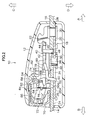
- Fig. 2 is a sectional view showing the overall configuration of a buckle device according to an embodiment of the present invention.
- Fig. 3 is a sectional view showing the overall configuration of a buckle device according to an embodiment of the present invention.
- Fig. 4 is an exploded perspective view showing the overall structure of a buckle device according to an embodiment of the present invention.
- In Fig. 4, the structure of a
buckle device 10 according to an embodiment of the present invention is illustrated in exploded perspective view. Further, in Fig. 3, the structure of thebuckle device 10 is illustrated in sectional view. - As shown in Fig. 3, the
buckle device 10 is provided with acase 12. Thecase 12 is formed as a box-shaped cylinder having an opening at either end in a length direction, with the opening at one end in a length direction being a tongue insertion opening 14 and the opening at the other end length direction being an anchor insertion opening 16. Further, abuckle body 18 that structures the device body is accommodated at an inner side of thecase 12. - The
buckle body 18 has abottom plate part 20 formed in a long flat plate shape along the length direction of thecase 12 and a pair ofside wall parts 22 extending integrally from both sides in a width direction of thebottom plate part 20 toward one side in a plate-thickness direction of the bottom plate part 20 (the side in the direction of Arrow C), and as a whole is formed with an open-top box-shaped cross section. At thebuckle body 18, aninsertion plate part 26 of atongue plate 24 that is inserted from the tongue opening 14 of thecase 12, is inserted between the pair ofside wall parts 22 from one end side in a length direction of the bottom plate part 20 (the side in the direction of Arrow B). - Further, the front edge part of an
anchor plate 28 that is inserted from theanchor opening 16 of thecase 12 is overlaid at the other end side in a length direction of the bottom plate part 20 (the side in the direction of Arrow A), and thebottom plate part 20 and theanchor plate 28 are coupled together and fixed by arivet 30 that passes through thebottom plate part 20 and theanchor plate 28. The anchor end side of theanchor plate 28 is fixed at the vehicle body at the seat side of the vehicle (both omitted from the drawings) and, in this way, thepresent buckle device 10 is attached to the vehicle. - In addition, an
ejector 32 is disposed between the pair ofside wall parts 22. A part of theejector 32 is engaged with a substantially rectangular throughhole 34 formed at thebottom plate part 20. Thethrough hole 34 is formed to be long in the length direction of thebottom plate part 20 and theejector 32 is able to slide within a predetermined range in the length direction of thebottom plate part 20 along the throughhole 34. - At an inner peripheral part of one end side in a length direction of the through hole 34 (the side in the direction of Arrow A), an
engagement projection 36 is formed so as to protrude, and is engaged with one end of anejector spring 38, which is a compression coil spring. The other end of theejector spring 38 is engaged with theejector 32 and theejector 32 is urged toward one end side in a length direction of the bottom plate part 20 (the side in the direction of Arrow B) by the urging force of theejector spring 38. - The
ejector 32 is slid toward the other end side in a length direction of thebottom plate part 20 against the urging force of theejector spring 38 when it is pushed by theinsertion plate part 26 of thetongue plate 24 inserted between the pair of side wall parts 22 (the state shown in Fig. 2). - On the other hand, the
present buckle device 10 is provided with alock plate 40. Thelock plate 40 is provided with abase part 42 formed in a long plate-shape along the length direction of thebottom plate part 20. A pair ofsupport parts 44 are formed so as to project toward either side in a width direction at the anchor end of the base part 42 (the end part at the side in the direction of Arrow A). The pair ofsupport parts 44 penetratesupport holes 46 formed at the respectiveside wall parts 22 of thebuckle body 18, and thelock plate 40 is supported by the pair ofside wall parts 22 so as to be rotatable around the pair of support parts 44 (the support holes 46) to a predetermined angle. - Further, at the anchor end side of the
base part 42, a pair ofarm parts 48 extend from either edge in a width direction toward thebottom plate part 20 side (the side in the direction of Arrow D). The pair ofarm parts 48 are formed such that the respective leading end sides are positioned above the slide trajectory of theejector 32, and when theejector 32 slides toward the other end side in a length direction of the bottom plate part 20 (the Arrow A direction side), the pair ofarm parts 48 are pushed toward the other end side in a length direction of thebottom plate part 20 and the base part 42 (the lock plate 40) rotates toward thebottom plate part 20 side (the Arrow D direction side; engagement position). - An
engagement piece 50 extends from the front edge of the base part 42 (the edge part at the Arrow B direction side) toward one side in a plate thickness direction of the base part 42 (the bottom plate part side; Arrow D direction side). Theengagement piece 50 is formed such that the leading edge side thereof (the Arrow D direction side) is slightly inclined toward the one end side in a length direction of the bottom plate part 20 (the Arrow B direction side). Further, the leading edge part of theengagement piece 50 corresponds to the throughhole 34 formed at thebottom plate part 20, and when thelock plate 40 is rotated toward thebottom plate part 20 side (the engagement position) theengagement piece 50 passes through the throughhole 34 and anengagement hole 26A in theinsertion plate part 26 inserted between the pair ofside wall parts 22, and restricts removal of the tongue plate 24 (supports the tongue plate 24) (the state shown in Fig. 2). - A
mounting part 32A is formed at a surface at one side in a thickness direction (the Arrow C direction side) of theejector 32 so as to correspond to theengagement piece 50 of thelock plate 40. In a state in which thetongue plate 24 is not inserted between the pair ofside wall parts 22, i.e., in a state in which theejector 32 is supported by the urging force of theejector spring 38 at the other side in a length direction (the Arrow B direction side) of the throughhole 34, themounting part 32A intervenes with the leading edge part of theengagement piece 50 and restricts rotation of thelock plate 40 toward thebottom plate part 20 side (the engagement position) (supports thelock plate 40 in a released position) (the state shown in Fig. 3). - In addition, a pair of
contact pieces 52 are provided at either side in a width direction of theengagement piece 50 so as to extend from the front edge of thebase part 42 toward the one end side (the Arrow B direction side) in a length direction of thebottom plate part 20. The pair ofcontact pieces 52 correspond to alock member 54. - The
lock member 54 is disposed at an opposite side to thebottom plate part 20 via the pair ofcontact pieces 52 and, as shown in Fig. 1, is provided with abody portion 56. Thebody portion 56 is a sintered metal manufactured by the powder metallurgy method and is formed in a substantially triangular cylindrical shape having a length direction along a direction opposed to the pair ofside wall parts 22. - Further, the
lock member 54 is provided with ashaft 58 that passes through the upper edge part (the edge part at the Arrow C direction side) of thebody portion 56 along a length direction thereof. Theshaft 58 is formed in a rod shape having a substantially rectangular cross section (a double D-cut shape) from a metallic material (stainless steel in the present embodiment). Theshaft 58 is provided so as to be integrally press fit into apress fit hole 59 having a substantially rectangular cross section (a double D-cut shape) formed at the upper edge part of thebody 56. The respective end parts in an axial direction of theshaft 58 project from either end in a length direction of thebody 56 and penetrateengagement holes 60 formed at the pair ofside wall parts 22 such that thebody 56 is supported at the pair ofside wall parts 22 so that it can oscillate integrally with theshaft 58. - A substantially plate-shaped pressed
part 62 is integrally formed at the upper edge side of the body portion 56 (the opposite side to the bottom plate part; the Arrow C direction side) so as to extend toward the side opposite to the bottom plate part 20 (the Arrow C direction side). The pressedpart 62 corresponds to arelease button 70 described in the following. - Further, a
lock surface 56A is formed at the lower edge side (thebottom plate part 20 side; the Arrow D direction side) of thebody portion 56, which is formed in a circular arc shape concentric with theshaft 58. In a state in which thelock plate 40 is disposed in the engagement position and thelock member 54 is disposed in the locking position (the state shown in Fig. 2), thelock surface 56A contacts against the upper surfaces (the surfaces at the Arrow C direction side) of thecontact pieces 52 of thelock plate 40. - In addition, a
contact surface 56B is formed at the side of one edge in a thickness direction (the Arrow A direction side) of thebody portion 56. In a state in which thelock plate 40 is disposed in the released position and thelock member 54 is disposed in the unlocked position (the state shown in Fig. 3), thecontact surface 56B contacts against the front edges of thecontact pieces 52 of thelock plate 40. - Further, as shown in Fig. 1, a
holder 64 is mounted at the other side in a thickness direction (the Arrow B direction side) of thebody portion 56. Theholder 64 is formed from a resin material and is provided with abase 65. Thebase 65 is formed lengthwise along the length direction of thebody portion 56 and is inserted into a mountinggroove 67 formed at thebody portion 56. - A pair of
latch parts 69 extend from either side in a length direction of the base 65 toward one edge side in a width direction (the Arrow A direction side) of thebody portion 56.Claw parts 71 are formed to extend from the respective leading ends of the pair oflatch parts 69 toward an inner side (thebody portion 56 side) and theclaw parts 71 are inserted into latch holes 73 formed at both end portions in a length direction of the body portion 56 (thelatch parts 69 and theclaw parts 71 are structured in the manner of a so-called "snap fit"). In this way, theholder 64 is mounted at thebody portion 56. - A
spring hold part 75 is formed at a central portion in a length direction of the base 65 so as to extend toward the side opposite to the body portion 56 (the Arrow B direction side). The spring holdpart 75 corresponds to alock spring 86 described in the following. - On the other hand, the
present buckle device 10 is provided with arelease button 70 provided at one end side in a length direction of thebuckle body 18. Therelease button 70 has anoperation part 72 that is operated by a passenger pressing it, and theoperation part 72 is formed in a box shape that opens toward the other end side in a length direction (the Arrow A direction side) of thebuckle body 18. - A pair of
arm parts 74 extend from either end in a width direction of theoperation part 72 toward the other end side in a length direction (the Arrow A direction side) of thebottom plate part 20. Projectingparts 76 are provided at the respective extremities of the pair ofarm parts 74 so as to respectively extend toward thebottom plate part 20 side (the Arrow D direction side). Claw parts 78 are formed at the respective extremities of the pair of projectingparts 76 so as to respectively project toward the side of the respective side wall parts 22 (the inner side) and the claw parts 78 are inserted intolong holes 80 respectively formed in the pair ofside wall parts 22. Eachlong hole 80 is formed lengthwise along the direction of insertion of the tongue plate 24 (the Arrow A direction) and each claw part 78 is able to move within a predetermined range along a length direction of thebottom plate part 20 in accordance with an inner peripheral portion of thelong holes 80. In this way, the direction of movement (operation direction) of therelease button 70 is restricted by thelong holes 80 to the length direction of thebottom plate part 20. - Further, a connecting
part 82 formed lengthwise along a direction opposing the pair ofarm parts 74 in a substantially rod shape bridges across between the respective extremities of the pair ofarm parts 74 such that the respective extremities of the pair ofarm parts 74 are connected by the connectingpart 82. - In addition, at the
release button 70, apressing part 84 is formed at the upper end side (the Arrow C direction side) of theoperation part 72 so as to project toward the other end side (the Arrow A direction side) in a length direction of thebottom plate part 20. Thepressing part 84 is disposed so as to face the pressedpart 62 of thelock member 54 described above, and when therelease button 70 is operated by pressing, the pressedpart 62 is pushed by thepressing part 84 toward the other end side (the Arrow A direction side) in a length direction of thebottom plate part 20 and thebody portion 56 of thelock member 54 oscillates around theshaft 58 toward the one end side (the Arrow B direction side; the unlocked position) in a length direction of thebottom plate part 20. - Further, a
lock spring 86, which is a compression coil spring, is disposed between theoperation part 72 of therelease button 70 and thelock member 54. Theholder 64 described above is disposed between one end of thelock spring 86 and thelock member 54, and the spring holdpart 75 of theholder 64 is engaged with the one end of thelock spring 86. The other end of thelock spring 86 is press contacted against a lower wall portion of theoperation part 72 of therelease button 70, and thelock member 54 is urged toward the locking position (the Arrow A direction side; the side opposite to the release button 70) by the urging force of thelock spring 86 via theholder 64. - Next, the mechanism of the present embodiment is explained.
- In the buckle device structured as described above, when the
insertion plate part 26 of thetongue plate 24 is inserted into thecase 12 from the tongue insertion opening 14 from the non-attached state shown in Fig. 3, the leading end of theinsertion plate part 26 contacts against and pushes the end of theejector 32, causing theejector 32 to slide to one end side in a length direction (the Arrow A direction side) of the throughhole 34 against the urging force of theejector spring 38, as shown in Fig. 2. - When the
ejector 32 slides a predetermined amount toward the one end side in a length direction of the throughhole 34, the mountingpart 32A of theejector 32 and theengagement piece 50 of thelock plate 40 are released from a state of opposition and theejector 32 pushes the pair ofarm parts 48 of thelock plate 40, causing thelock plate 40 to rotate toward thebottom plate part 20 side (the engagement position). - As a result, the leading edge part of the
engagement piece 50 moves into the proximity of thebottom plate part 20. Further, in this state, theengagement hole 26A of theinsertion plate part 26 and the throughhole 34 formed at thebottom plate part 20 overlap each other. Accordingly, in this state, as shown in Fig. 2, the rotatedengagement piece 50 passes through theengagement hole 26A of theinsertion plate part 26 and the throughhole 34 of thebottom plate part 20. - Further, by rotating the
lock plate 40 to the engagement position, the state of contact between thecontact pieces 52 of thelock plate 40 and thecontact surface 56B of thelock member 54 is released. Then, since the lock member is receiving the urging force of thelock spring 86 via theholder 64, thebody portion 56 of thelock member 54 oscillates toward the other end side (the Arrow A direction side; locking position) in a length direction of thebottom plate portion 20 due to the urging force of thelock spring 86 so as to engage with the rotation of thelock plate 40, and thelock surface 56A of thebody portion 56 contacts the upper surfaces (the Arrow C direction side surface) of the contact pieces 52 (the state shown in Fig. 2). As a result, rotation of thelock plate 40 toward the released position (rotation of the engagement piece in a direction away from the bottom plate part 20) is restricted and, as a result, an attached state (held state) of thetongue plate 24 with respect to the buckle device is achieved. - On the other hand, when the
operation part 72 of therelease button 70 is pressed and operated in the above attached state of thetongue plate 24, the pressedportion 62 of thelock member 54 is pushed toward the other end side (the Arrow A direction side) in a length direction of thebottom plate part 20 by thepressing part 84 of therelease button 70 and thebody portion 56 of thelock member 54 oscillates toward the one end side (the Arrow B direction side; the unlocked position) in a length direction of thebottom plate part 20 against the urging force of thelock spring 86. - As a result, the state of contact between the
lock surface 56A of thebody portion 56 and thecontact pieces 52 of thelock plate 40 is released and the rotation restriction (movement prevention) of thelock plate 40 by thelock member 54 is released. Moreover, since the urging force of theejector spring 38 is acting on theengagement piece 50 of thelock plate 40 via theejector 32 and theinsertion plate part 26 of thetongue plate 24, a component force acts on theengagement piece 50 in a direction away from thebottom plate part 20. As a result, thelock plate 40 rotates away from thebottom plate part 20 toward the released position due to the component force acting on theengagement piece 50 and the holding of thetongue plate 24 by theengagement piece 50 is released. As a result, theejector 32 is slid toward the other end side (the Arrow B direction side) in a length direction of the throughhole 34 by the urging force of theejector spring 38 and theinsertion plate part 26 of thelock plate 40 is discharged from theinsertion opening 14 of thecase 12 by the sliding of theejector 32. - In the
buckle device 10 according to the present embodiment thebody portion 56 of thelock member 54 is formed from a sintered metal, and theshaft 58 that supports thebody portion 56 at thebuckle body 18 is formed from a metallic material (stainless steel in the present embodiment) and is press fit integrally into thebody portion 56. Accordingly, the strength of theshaft 58, which receives the load of thebody portion 56, is sufficiently secured and miniaturization and weight securement of thebody portion 56 can both be achieved. - Moreover, since, as described above, the
body portion 56 is formed from a sintered metal, the degree of part precision of thebody portion 56 is greatly improved over a case where the lock member is formed from pressed parts. As a result, even when, for example, a low-cost coating is applied to thebody portion 56, it is possible to secure the function (quality) of thelock member 54 and value engineering (VE) can be achieved. - Further, since conventional buckle devices have been structured such that one end of a lock spring urging a lock member to a locking position is directly engaged with a pressed part lock member (made of iron), the problem existed that the one end (the engaging portion described above) of the lock spring suffered wear due to friction between the one end of the lock spring and the lock member when the lock member oscillates.
- In this regard, in the
buckle device 10 according to the present embodiment, theholder 64 formed from a resin is mounted at the body portion of thelock member 54 and one end of thelock spring 86 is engaged with the spring holdpart 75 of theholder 64. As a result, it is possible to prevent wear of the one end of thelock spring 86 caused by oscillation of thebody portion 56 and the durability of thelock spring 86 is greatly improved. As a result, it is possible, for example, to configure a smaller wire diameter for thelock spring 86, to reduce the urging force and to improve the operationality of therelease button 70, and the function (quality) of thelock spring 86 can be secured while also achieving a reduction in the cost thereof. - As explained above, in the
buckle device 10 according to the present embodiment, miniaturization and weight securement of thelock member 54 can both be achieved while also securing the necessary strength thereof.
Claims (7)
- A buckle device, comprising:a lock plate provided so as to be movable between an engagement position, at which the lock plate engages with a tongue plate inserted into a body of the device and holds the tongue plate within the body of the device, and a released position, at which the lock plate has been released from holding the tongue plate; anda lock member havinga body portion provided so as to be able to oscillate between a locking position, at which the body portion engages with the lock plate positioned at the engagement position and prevents the lock plate from moving toward the released position, and an unlocked position, at which the body portion has been released from preventing movement of the lock plate, anda shaft that supports the body portion at the body of the device, whereinthe body portion is formed from a sintered metal and the shaft is formed from a metal and is integrally press fit into the body portion.
- The buckle device of claim 1, further comprising:a release button that is provided at the body of the device and that causes the body portion of the lock member to oscillate toward the unlocked position when the release button is operated by being pressed;a lock spring that is provided between the release button and the body portion of the lock member and that urges the body portion of the lock member toward the locking position; anda holder, formed from a resin, that is provided between the body portion of the lock member and the lock spring and is engaged with one end of the lock spring.
- The buckle device of claim 1, wherein the metal includes stainless steel.
- A buckle device, comprising:a lock plate provided so as to be movable between an engagement position, at which the lock plate engages with a tongue plate inserted into a body of the device and holds the tongue plate within the body of the device, and a released position, at which the lock plate has been released from holding the tongue plate; anda lock member havinga body portion provided so as to be able to oscillate between a locking position, at which the body portion engages with the lock plate positioned at the engagement position and prevents the lock plate from moving toward the released position, and an unlocked position, at which the body portion has been released from preventing movement of the lock plate, anda shaft that supports the body portion at the body of the device, whereinthe body portion is formed from a sintered metal.
- The buckle device of claim 4, wherein the shaft is formed from a metal and is integrally press fit into the body portion.
- The buckle device of claim 5, wherein the metal includes stainless steel.
- A buckle device, comprising:a lock plate provided so as to be movable between an engagement position, at which the lock plate engages with a tongue plate inserted into a body of the device and holds the tongue plate within the body of the device, and a released position, at which the lock plate has been released from holding the tongue plate;a lock member havinga body portion provided so as to be able to oscillate between a locking position, at which the body portion engages with the lock plate positioned at the engagement position and prevents the lock plate from moving toward the released position, and an unlocked position, at which the body portion has been released from preventing movement of the lock plate, anda shaft that supports the body portion at the body of the device;a release button that is provided at the body of the device and that causes the body portion of the lock member to oscillate toward the unlocked position when the release button is operated by being pressed;a lock spring that is provided between the release button and the body portion of the lock member and that urges the body portion of the lock member toward the locking position; anda holder, formed from a resin, that is provided between the body portion of the lock member and the lock spring and is engaged with one end of the lock spring.
Applications Claiming Priority (1)
| Application Number | Priority Date | Filing Date | Title |
|---|---|---|---|
| JP2005304552A JP2007111178A (en) | 2005-10-19 | 2005-10-19 | Buckle device |
Publications (3)
| Publication Number | Publication Date |
|---|---|
| EP1776886A2 true EP1776886A2 (en) | 2007-04-25 |
| EP1776886A3 EP1776886A3 (en) | 2008-03-05 |
| EP1776886B1 EP1776886B1 (en) | 2016-03-23 |
Family
ID=37649425
Family Applications (1)
| Application Number | Title | Priority Date | Filing Date |
|---|---|---|---|
| EP06021894.8A Not-in-force EP1776886B1 (en) | 2005-10-19 | 2006-10-19 | Buckle device |
Country Status (4)
| Country | Link |
|---|---|
| US (1) | US7523530B2 (en) |
| EP (1) | EP1776886B1 (en) |
| JP (1) | JP2007111178A (en) |
| CN (1) | CN100593984C (en) |
Families Citing this family (5)
| Publication number | Priority date | Publication date | Assignee | Title |
|---|---|---|---|---|
| JP5653741B2 (en) * | 2010-12-15 | 2015-01-14 | タカタ株式会社 | Buckle and seat belt device provided with the same |
| CN103171748B (en) * | 2011-12-26 | 2015-06-03 | 中国科学院沈阳自动化研究所 | Low-noise separation mechanism for separating appendage of self-governing underwater vehicle |
| US9974365B2 (en) * | 2014-11-07 | 2018-05-22 | Ford Global Technologies, Llc | Buckle guide |
| MY195143A (en) * | 2019-03-19 | 2023-01-11 | Thaib Najiyah | A Clamping Device |
| WO2021257912A1 (en) * | 2020-06-18 | 2021-12-23 | Harry Miller Co., Llc | Magnetically guided latch |
Citations (1)
| Publication number | Priority date | Publication date | Assignee | Title |
|---|---|---|---|---|
| JP2003125811A (en) | 2001-10-29 | 2003-05-07 | Tokai Rika Co Ltd | Buckle device |
Family Cites Families (8)
| Publication number | Priority date | Publication date | Assignee | Title |
|---|---|---|---|---|
| US3760467A (en) * | 1971-06-08 | 1973-09-25 | Allied Chem | Safety belt buckle |
| SE447535B (en) * | 1980-06-16 | 1986-11-24 | Stil Ind Ab | Seat belt buckle with a detachable coupling part and a detachable coupling part |
| FR2582916B1 (en) * | 1985-06-10 | 1987-09-18 | Peugeot Aciers Outillages | BUCKLE, ESPECIALLY A SEAT BELT. |
| JP3650271B2 (en) | 1998-07-27 | 2005-05-18 | 株式会社東海理化電機製作所 | buckle |
| JP3432471B2 (en) | 1999-12-08 | 2003-08-04 | カツヤマファインテック株式会社 | Buckle for seat belt |
| WO2001049144A1 (en) * | 1999-12-30 | 2001-07-12 | Delphi Technologies, Inc. | Seat restraint buckle assembly |
| JP2001224407A (en) * | 2000-02-16 | 2001-08-21 | Katsuyama Finetech Kk | Buckle for seat belt |
| JP2003137064A (en) * | 2001-11-02 | 2003-05-14 | Tokai Rika Co Ltd | Buckle device |
-
2005
- 2005-10-19 JP JP2005304552A patent/JP2007111178A/en active Pending
-
2006
- 2006-10-17 CN CN200610136360.XA patent/CN100593984C/en not_active Expired - Fee Related
- 2006-10-18 US US11/582,450 patent/US7523530B2/en not_active Expired - Fee Related
- 2006-10-19 EP EP06021894.8A patent/EP1776886B1/en not_active Not-in-force
Patent Citations (1)
| Publication number | Priority date | Publication date | Assignee | Title |
|---|---|---|---|---|
| JP2003125811A (en) | 2001-10-29 | 2003-05-07 | Tokai Rika Co Ltd | Buckle device |
Also Published As
| Publication number | Publication date |
|---|---|
| JP2007111178A (en) | 2007-05-10 |
| US20070084026A1 (en) | 2007-04-19 |
| CN1951249A (en) | 2007-04-25 |
| EP1776886B1 (en) | 2016-03-23 |
| CN100593984C (en) | 2010-03-17 |
| EP1776886A3 (en) | 2008-03-05 |
| US7523530B2 (en) | 2009-04-28 |
Similar Documents
| Publication | Publication Date | Title |
|---|---|---|
| EP1018307B1 (en) | Buckle | |
| US8973956B2 (en) | Latch device | |
| US20040207191A1 (en) | Height adjuster or adjustable turning loop | |
| JPH10203304A (en) | Belt buckle | |
| JP2012211460A (en) | Seat retainer | |
| EP1776886B1 (en) | Buckle device | |
| US6463639B1 (en) | Buckle | |
| JP2008041583A (en) | Switch device and assembly method thereof | |
| JPH09510042A (en) | Safety switch | |
| CN109927666B (en) | Buckle for seat belt device | |
| EP1671558B1 (en) | Buckle device | |
| US6550112B2 (en) | Closure for a seat belt | |
| US7552518B2 (en) | Seat belt buckle for use with pretensioner | |
| CN116548707A (en) | Belt buckle device | |
| JPH08173213A (en) | Buckle device | |
| US7370393B2 (en) | Seat belt buckle for use with pretensioner | |
| US9402446B2 (en) | Belt buckle with release lock | |
| JP2006122553A (en) | Buckle device | |
| JPH0642846B2 (en) | Buckle for automobile safety belt | |
| US7458136B2 (en) | Shock-absorbing safety belt buckle | |
| JP2006122552A (en) | Buckle device | |
| EP0858927A2 (en) | Reclining device | |
| JP2008284129A (en) | Fasteners, elongate bodies, portable devices, watches, accessories | |
| JPH0414007Y2 (en) | ||
| JPS6239694Y2 (en) |
Legal Events
| Date | Code | Title | Description |
|---|---|---|---|
| PUAI | Public reference made under article 153(3) epc to a published international application that has entered the european phase |
Free format text: ORIGINAL CODE: 0009012 |
|
| AK | Designated contracting states |
Kind code of ref document: A2 Designated state(s): AT BE BG CH CY CZ DE DK EE ES FI FR GB GR HU IE IS IT LI LT LU LV MC NL PL PT RO SE SI SK TR |
|
| AX | Request for extension of the european patent |
Extension state: AL BA HR MK YU |
|
| RIN1 | Information on inventor provided before grant (corrected) |
Inventor name: MUROMACHI, TESUSHIC/O K.K. TOKAI-RIKA-DENKI-SEISAK |
|
| RIN1 | Information on inventor provided before grant (corrected) |
Inventor name: MUROMACHI, TETSUSHIC/O K.K. TOKAI-RIKA-DENKI-SEISA |
|
| PUAL | Search report despatched |
Free format text: ORIGINAL CODE: 0009013 |
|
| AK | Designated contracting states |
Kind code of ref document: A3 Designated state(s): AT BE BG CH CY CZ DE DK EE ES FI FR GB GR HU IE IS IT LI LT LU LV MC NL PL PT RO SE SI SK TR |
|
| AX | Request for extension of the european patent |
Extension state: AL BA HR MK YU |
|
| 17P | Request for examination filed |
Effective date: 20080619 |
|
| AKX | Designation fees paid |
Designated state(s): DE FR GB |
|
| 17Q | First examination report despatched |
Effective date: 20081205 |
|
| GRAP | Despatch of communication of intention to grant a patent |
Free format text: ORIGINAL CODE: EPIDOSNIGR1 |
|
| INTG | Intention to grant announced |
Effective date: 20151022 |
|
| GRAS | Grant fee paid |
Free format text: ORIGINAL CODE: EPIDOSNIGR3 |
|
| GRAA | (expected) grant |
Free format text: ORIGINAL CODE: 0009210 |
|
| AK | Designated contracting states |
Kind code of ref document: B1 Designated state(s): DE FR GB |
|
| REG | Reference to a national code |
Ref country code: GB Ref legal event code: FG4D |
|
| REG | Reference to a national code |
Ref country code: DE Ref legal event code: R096 Ref document number: 602006048314 Country of ref document: DE |
|
| REG | Reference to a national code |
Ref country code: FR Ref legal event code: PLFP Year of fee payment: 11 |
|
| REG | Reference to a national code |
Ref country code: DE Ref legal event code: R097 Ref document number: 602006048314 Country of ref document: DE |
|
| PLBE | No opposition filed within time limit |
Free format text: ORIGINAL CODE: 0009261 |
|
| STAA | Information on the status of an ep patent application or granted ep patent |
Free format text: STATUS: NO OPPOSITION FILED WITHIN TIME LIMIT |
|
| 26N | No opposition filed |
Effective date: 20170102 |
|
| REG | Reference to a national code |
Ref country code: FR Ref legal event code: PLFP Year of fee payment: 12 |
|
| REG | Reference to a national code |
Ref country code: DE Ref legal event code: R084 Ref document number: 602006048314 Country of ref document: DE |
|
| REG | Reference to a national code |
Ref country code: FR Ref legal event code: PLFP Year of fee payment: 13 |
|
| PGFP | Annual fee paid to national office [announced via postgrant information from national office to epo] |
Ref country code: FR Payment date: 20190913 Year of fee payment: 14 |
|
| PGFP | Annual fee paid to national office [announced via postgrant information from national office to epo] |
Ref country code: DE Payment date: 20191008 Year of fee payment: 14 |
|
| PGFP | Annual fee paid to national office [announced via postgrant information from national office to epo] |
Ref country code: GB Payment date: 20191018 Year of fee payment: 14 |
|
| REG | Reference to a national code |
Ref country code: DE Ref legal event code: R119 Ref document number: 602006048314 Country of ref document: DE |
|
| GBPC | Gb: european patent ceased through non-payment of renewal fee |
Effective date: 20201019 |
|
| PG25 | Lapsed in a contracting state [announced via postgrant information from national office to epo] |
Ref country code: FR Free format text: LAPSE BECAUSE OF NON-PAYMENT OF DUE FEES Effective date: 20201031 Ref country code: DE Free format text: LAPSE BECAUSE OF NON-PAYMENT OF DUE FEES Effective date: 20210501 |
|
| PG25 | Lapsed in a contracting state [announced via postgrant information from national office to epo] |
Ref country code: GB Free format text: LAPSE BECAUSE OF NON-PAYMENT OF DUE FEES Effective date: 20201019 |