EP1776848B1 - Method and circuit arrangement for operating a discharge lamp - Google Patents
Method and circuit arrangement for operating a discharge lamp Download PDFInfo
- Publication number
- EP1776848B1 EP1776848B1 EP05780821A EP05780821A EP1776848B1 EP 1776848 B1 EP1776848 B1 EP 1776848B1 EP 05780821 A EP05780821 A EP 05780821A EP 05780821 A EP05780821 A EP 05780821A EP 1776848 B1 EP1776848 B1 EP 1776848B1
- Authority
- EP
- European Patent Office
- Prior art keywords
- lamp
- frequency
- operating
- operating phase
- electrode tip
- Prior art date
- Legal status (The legal status is an assumption and is not a legal conclusion. Google has not performed a legal analysis and makes no representation as to the accuracy of the status listed.)
- Expired - Lifetime
Links
Images

Classifications
-
- H—ELECTRICITY
- H05—ELECTRIC TECHNIQUES NOT OTHERWISE PROVIDED FOR
- H05B—ELECTRIC HEATING; ELECTRIC LIGHT SOURCES NOT OTHERWISE PROVIDED FOR; CIRCUIT ARRANGEMENTS FOR ELECTRIC LIGHT SOURCES, IN GENERAL
- H05B41/00—Circuit arrangements or apparatus for igniting or operating discharge lamps
- H05B41/14—Circuit arrangements
- H05B41/26—Circuit arrangements in which the lamp is fed by power derived from DC by means of a converter, e.g. by high-voltage DC
- H05B41/28—Circuit arrangements in which the lamp is fed by power derived from DC by means of a converter, e.g. by high-voltage DC using static converters
- H05B41/288—Circuit arrangements in which the lamp is fed by power derived from DC by means of a converter, e.g. by high-voltage DC using static converters with semiconductor devices and specially adapted for lamps without preheating electrodes, e.g. for high-intensity discharge lamps, high-pressure mercury or sodium lamps or low-pressure sodium lamps
- H05B41/292—Arrangements for protecting lamps or circuits against abnormal operating conditions
- H05B41/2928—Arrangements for protecting lamps or circuits against abnormal operating conditions for protecting the lamp against abnormal operating conditions
-
- Y—GENERAL TAGGING OF NEW TECHNOLOGICAL DEVELOPMENTS; GENERAL TAGGING OF CROSS-SECTIONAL TECHNOLOGIES SPANNING OVER SEVERAL SECTIONS OF THE IPC; TECHNICAL SUBJECTS COVERED BY FORMER USPC CROSS-REFERENCE ART COLLECTIONS [XRACs] AND DIGESTS
- Y02—TECHNOLOGIES OR APPLICATIONS FOR MITIGATION OR ADAPTATION AGAINST CLIMATE CHANGE
- Y02B—CLIMATE CHANGE MITIGATION TECHNOLOGIES RELATED TO BUILDINGS, e.g. HOUSING, HOUSE APPLIANCES OR RELATED END-USER APPLICATIONS
- Y02B20/00—Energy efficient lighting technologies, e.g. halogen lamps or gas discharge lamps
Definitions
- the invention relates to a method and a circuit arrangement for operating a discharge lamp.
- the method as invented and the circuit arrangement as invented are intended especially for HID [high intensity gas discharge] lamps or UHP [ultra high performance] lamps.
- the invention further relates to an illumination unit with a discharge lamp and such a circuit arrangement as well as a projection system with a projection display and such an illumination unit.
- Lamps of this type can be operated principally on DC as well as on AC. In general, however, operating on AC is preferred, because this prevents fast erosion of the electrodes and the efficiency of the lamps can be raised.
- the hazard of unstable arc discharges that cause flickering of the emitted light stream also increases, especially when operating on AC, owing to the constant change in polarity.
- This is mainly due to the fact that the arc discharge depends on the temperature and the state of the surface of the electrodes and, moreover, the time-dependent patterns of the electrode temperature differ in the phases in which the electrodes work as anode and cathode. This, in turn, causes considerable changes in the electrode temperature during a period of the lamp current.
- variation in the emitted light stream can distort the appearance, however, if for example one of the ground color images is reproduced with a different brightness than the other ground images.
- US 2002/0105288A1 discloses a lighting method for an UHP discharge lamp in which by combining the use of electrodes having an increased thermal capacity (or an increased current withstanding capability) with time periods for which the usual alternating lamp current assumes a very low frequency, thermal electrons are allowed to flow from one electrode to the other continuously for an accordingly longer time than in case of the alternating current frequency for usual lighting, so that the surfaces of the thermal electron receiving electrode is heated and slightly fused.
- the roughening and projections on the related surface of the electrode which have been formed during usual lighting due to at least one of a thermal factor, an oxygen factor and a silicon factor, are eliminated and the original spherical electrode surface is restored.
- US 2004/0000880A1 discloses a lighting method for a high-pressure discharge lamp in which a first lower frequency for a first period of time is selected such that a protrusion is forming on an electrode tip and a second higher frequency for a second period of time is selected such that the protrusion formed on the tip of the electrode is melted back.
- the object is achieved in accordance with claim 1 by a method for operating a HID or UHP discharge lamp with an alternating activation of a first and a second operating phase, wherein during the first operating phase the lamp current has a first higher frequency, so that on a first thick electrode tip a second thinner electrode tip is grown, and during the second operating phase the lamp current has a second lower frequency, so that the second thinner electrode tip is melted down and its material is deposited at least to a large extent on the first thick electrode tip, so that a third electrode tip is created with a diameter larger than the diameter of the first electrode tip.
- the object is further achieved as claimed in claim 14 by means of a circuit arrangement for executing this method.
- a lamp can be operated on a relatively high frequency of the lamp AC (where this frequency can be considerably higher than the frequency of known lamp ACs superimposed with the above mentioned power pulses), such that the advantages related to it, viz. a mostly more stable arc discharge due to the thinner electrode tips as well as lower voltage drop at the electrodes, can be utilized, without having to accept the disadvantages usually related to the high frequencies (foremost being a heavy electrode burnout as well as a comparatively frequent arc jumps or unstable arc discharges owing to the formation of multiple electrode tips). These advantages are achieved without having to superimpose power pulses on the lamp AC in the known manner.
- the claims 2 and 6 disclose a conditioning phase and a preferred third frequency range for this phase, respectively.
- the claims 3, 4, 5, 7 and 8 contain preferred areas of the first or the second frequency, as the case may be, while preferred time ratios between the first and second operating phases are given in the claims 9 and 10.
- the claims 11 and 12 contain a switch-on operating phase, which is activated preferably in lieu of the second operating phase after switching on the lamp, if the lamp is being used not in continuous operation but only for comparatively shorter periods each time.
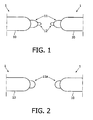
- Figs. 1 and 2 show schematically the mutually facing end areas of two electrodes 1 of a (high-intensity) gas discharge lamp, between which an arc discharge (not shown) forms in the operating state,
- Peaks 11, 12; 11a whose growth i.e, length and diameter depends on various operating parameters of the lamp, and which can cause certain desired or undesired properties in the lamp appear on the front mutually facing surfaces of the electrode bodies 10 during the operation of the discharge lamp.
- electrode tips with comparatively small diameters can be generated by using comparatively high operating frequencies f of, for example, between about 300 Hz and about 1000 Hz and tips with a comparatively large diameter by using comparatively low operating frequencies f of, for example, between about 20 to 150 or 200 Hz.
- a disadvantage of relatively thick tips as against thin tips is that the heat transport from the free end of the thick tip in the direction of the electrode body 10 is relatively heavy.
- the result of a relatively high operating voltage f of the lamp AC is generally that especially after a long operating period, a heavier burnout of the electrodes (and thus increase in the burning voltage) can be observed and/or that generally relatively thin peaks form on the electrode between which then the arc jumps here and there.
- the operating parameters of the lamp especially the frequency of the lamp AC are set and changed or controlled such that the electrode tips assume the shapes shown in Figs. 1 and 2 alternately.
- a relatively thick first electrode tip 11 has built up at the free end of the electrode body 10, on which tip a relatively thin second electrode tip 12 has grown.
- the thin second electrode tip 12 has melted down and its material has deposited to a large extent on the thick first electrode tip 11, so that now a single third electrode tip 11 a has developed with a diameter larger than the diameter of the first electrode tip 11 in Fig. 1 .
- the alternating change between these two electrode shapes prevents multiple peak formation as well as a resultant arc jumping at least to a large extent, as it also limits or reduces electrode burnout during the life of the lamp and the related rise in the burning voltage.
- Suitable frequencies of the lamp AC are preferably selected as operating parameters of the lamp by means of which these electrode forms are generated alternatingly and activated at appropriate intervals and periods.
- the lamp can be operated during a first operating phase on a lamp AC with a relatively high first frequency f 1 in the range between about 300 Hz and about 3000 Hz.
- the frequency of the lamp AC is switched over at definite intervals in a second operating phase (regeneration phase) to a relatively low second frequency f 2 , so that the thin second electrode tip 12 melts down and its material deposits at least to a large extent on the thick first electrode tip 11.
- the thick third electrode tip 11 as shown in Fig. 2 is created exclusively, with a diameter generally somewhat larger than that of the first electrode tip 11 as shown Fig. 1 .
- the second frequency f 2 can be in the range between about 0 and about 300 Hz, preferably between about 20 and about 200 Hz, or between about 1/20 and about 1/2 the first frequency f 1 .
- a DC component whose duration is between about 0.1 and about 10 seconds can also be applied to the lamp.
- This DC component is preferably run with a first and then with the opposite second polarity.
- the first operating phase is changed over to again so that again a thin second electrode tip 12 is formed.
- the second operating phase is activated preferably regularly after a duration of the first operating phase of between about 0.5 and about 10 hours has ended, depending on the type of lamp, where the second operating phase has preferably a duration of between about 0.1 and about 3600 seconds.
- Differentiation is preferably made between the case where the lamp is used at least to a large extent in a continuous mode and the case where the lamp is switched on for relatively short durations at and then switched off again.
- the operating period of the lamp is taken and after said period of the first operating phase, the second operating phase of the said duration is activated before the first operating phase is returned to.
- the second operating phase can always be activated in the form of a switch-on operating phase after switching on the lamp, before preferably only the first operating phase is then used.
- the above-mentioned operating parameters are also especially set such that no multiple thin electrode tips can be formed during the first operating phase due to the limited lateral extension of the thicker third electrode tip 11 a.
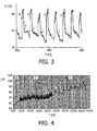
- Fig. 3 shows the pattern of the burning voltage U in Voltss for a high intensity discharge lamp over time T in hours, where the higher first frequency f 1 , of the lamp AC is around 500 Hz during the first operating phase marked as "I” and the lower second frequency f 2 during the second operating phase marked "II” at about 90 Hz.
- the burning voltage U during the first operating phase I drops to a value of about 72 to 74 Volts starting from a value of about 80 to 81 Volts.
- the thin second electrode tips 12 formed as shown in Fig. 1 are melted due to the second operating phase II with a duration of about 15 minutes each activated on reaching this low burning voltage, and in this manner the thicker third electrode tips 11a are generated or regenerated as shown in Fig. 2 such that the burning voltage again climbs to a value of about 80 to 81 Volts.
- Fig. 4 shows a time-compressed representation of the pattern of the mean burning voltage of UHP lamps with a power of 150 Watt for three different modes of operation.
- the lamp was operated exclusively at a high first frequency f 1 of the 500 Hz lamp AC corresponding to the above-described first operating phase. It can be easily recognized that, as mentioned above, the burning voltage rises overall due to the burnout of the electrodes after a relatively long operating period, here of about 40 working hours.
- the pattern of the mean operating voltage U shown in area "2" was obtained for a second mode of operation, in which the said first operating phase alternated with a second operating phase.
- the lamp AC again had a first frequency f 1 of 500 Hz, while the second frequency f 2 was 90 Hz in the second operating phase.
- the second operating phase was activated about every two hours for about 90 seconds.
- the pattern of the mean burning voltage U is depicted in the area "3" for a third mode of operation, which corresponds to the second mode, with the exception that the second operating phase was activated only about every eleven hours.
- Said long-term rise in the burning voltage can be further reduced, if the low second frequency f 2 of the lamp AC activated in the second operating phase is reduced in the course of the life of the lamp, for example from initially 90 Hz to 80 or 70 Hz.
- the first-time generation of the relatively thick third electrode tip 11a takes place preferably during a conditioning phase (in the factory etc.) in which the lamp is operated after switching on first at a relatively low conditioning frequency f K of the lamp AC in the range from, for example, about 20 to 200 Hz, preferably 90 Hz, for a period of time between about 0.1 and 10 minutes or even considerably longer if required.
- the high first frequency f 1 for the later first operating phase can then be defmed preferably in dependence on the value of the conditioning frequency f K in the range between about 2*f K and about 15*f K .
- a power pulse with the same polarity and a duration of about six percent of the period can be superimposed in the conditioning phase of each period of the lamp AC prior to a change of polarity, to improve the stability of the arc discharge during this conditioning phase.
- the thick third electrode tip 11 a in the course of the manufacture of the lamp by suitably molding the electrode material.
- a preferred numerical example for the operation of a UHP lamp is given below.
- a switch-on operating phase for about 0.1 to 10 minutes, preferably about 90 seconds with a third frequency f 3 of the lamp AC between about 20 and about 200 Hz, preferably about 100 Hz.
- This third frequency f 3 can also be mostly equal to the conditioning frequency f K or the second frequency f 2 during the second operating phase and serves to create the thick third electrode tip 11 a.
- the first operating phase is activated, in which the lamp AC has a first frequency f 1 of about 500 Hz.
- the second operating phase is activated for a period of about 90 seconds with a second frequency f 2 of about 100 Hz, before subsequently a switch-over to the first operating phase takes place.
- Fig. 5 finally shows a schematic block circuit diagram of an embodiment of a circuit arrangement for generating the lamp AC with the frequencies described above for a discharge lamp 31 from an AC voltage U ac present at the input of the circuit arrangement, of for example about 100 to 240 volts, as well as essential components of a projection system.
- the circuit arrangement contains a rectifier stage 10, a power/current controller 11, a voltage converter 12, a control unit 20, a commutator with ignition stage 30 as well as an image processor 40, on which a signal V of the video/graphics to be represented is present for image generation.
- the AC voltage U ac is converted into a DC voltage through the rectifier stage 10. From this DC voltage the power/current controller 11 generates a DC that has a current able for the discharge lamp 31 concerned by the power/current controller 11, which DC is superimposed as required with power pulses during a conditioning phase or the switch-on operating phase. For this purpose, the power/current controller 11 is accordingly controlled by the control unit 20.
- the generated DC is converted into a predominantly rectangular lamp AC with a first or second frequency f 1 , f 2 corresponding to the above-described alternatingly activated (first or second) operating phases after the conditioning phase or the switch-on operating phase by means of the commutator 30.
- the voltage converter 13, which is fed rectifier stage 10 is used for voltage supply of the power/current controller 11.
- the projection system is composed in essence he discharge lamp 31, an optical integrator 32, a color modulator 33, a display 34 as well as a lens system 35.
- the color modulator 33 and the display 34 are controlled in known manner by the image processor 40 in dependence on the video/graphics signal V present on it.
- the control unit 20 and the image processor 40 are interlinked through a communication connection and synchronized and designed in such a manner that the generation of the power pulses takes place in the switch-on operating phase by the power/current controller 11 and the commutation of the DC by the commutator 30 takes place with the above-described frequencies f 1 , f 2 in the first or second operating phase with the predefined time distances and durations.
- the burning voltage of the lamp 31 can be monitored in a manner known per se in order to reduce the second frequency f 2 , in case of a beginning rise in accordance with the invention, in accordance with the above explanation during the second operating phase against the initially defined value.
- control unit 20 and/or the image processor 40 are accordingly programmed to suit this purpose and provided with a memory in which the said operating parameters of the said operating phases are stored.
- the discharge lamp in illumination units for projection systems which react sensitively to light fluctuations during the lamp power period (such as for example DLP- and LCOS-systems)
- the following should preferably be observed in respect of the selection of the operating frequencies f 1 and f 2 :
- the third frequency f 3 of the switch-on operating phase can also be defined where its synchronization is, however, not so critical due to the generally short duration of the switch-on operating phase.
- the circuit arrangement for execution of the method as invented preferably contains particularly the control unit 20, a microprocessor or microcontroller with a software program, by means of which the explained method steps can be executed or controlled.
Landscapes
- Circuit Arrangements For Discharge Lamps (AREA)
Abstract
Description
- The invention relates to a method and a circuit arrangement for operating a discharge lamp. The method as invented and the circuit arrangement as invented are intended especially for HID [high intensity gas discharge] lamps or UHP [ultra high performance] lamps. The invention further relates to an illumination unit with a discharge lamp and such a circuit arrangement as well as a projection system with a projection display and such an illumination unit.
- Lamps of this type can be operated principally on DC as well as on AC. In general, however, operating on AC is preferred, because this prevents fast erosion of the electrodes and the efficiency of the lamps can be raised.
- However, the hazard of unstable arc discharges that cause flickering of the emitted light stream also increases, especially when operating on AC, owing to the constant change in polarity. This is mainly due to the fact that the arc discharge depends on the temperature and the state of the surface of the electrodes and, moreover, the time-dependent patterns of the electrode temperature differ in the phases in which the electrodes work as anode and cathode. This, in turn, causes considerable changes in the electrode temperature during a period of the lamp current. In order to have an advantageous impact on these variations, it is known to generate, at the end of each half period of the lamp current i.e. before a change in the polarity, a power pulse with the same polarity as the half period to be changed and to superimpose it on the lamp current such that the total current is increased and the electrode temperature rises. This can improve the stability of the arc discharge considerably.
- The effect of these power pulses is that the lamp is operated on a lamp AC that has more or less strongly manifest pulse-like components, which in turn cause a pulse-like enhanced light stream.
- Especially in color projection displays that work by time-sequential color reproduction methods, variation in the emitted light stream can distort the appearance, however, if for example one of the ground color images is reproduced with a different brightness than the other ground images.
-
US 2002/0105288A1 discloses a lighting method for an UHP discharge lamp in which by combining the use of electrodes having an increased thermal capacity (or an increased current withstanding capability) with time periods for which the usual alternating lamp current assumes a very low frequency, thermal electrons are allowed to flow from one electrode to the other continuously for an accordingly longer time than in case of the alternating current frequency for usual lighting, so that the surfaces of the thermal electron receiving electrode is heated and slightly fused. By this, the roughening and projections on the related surface of the electrode which have been formed during usual lighting due to at least one of a thermal factor, an oxygen factor and a silicon factor, are eliminated and the original spherical electrode surface is restored. -
US 2004/0000880A1 discloses a lighting method for a high-pressure discharge lamp in which a first lower frequency for a first period of time is selected such that a protrusion is forming on an electrode tip and a second higher frequency for a second period of time is selected such that the protrusion formed on the tip of the electrode is melted back. - It is an object of the invention to create a method and a circuit arrangement for operating a discharge lamp, by means of which a stable arc discharge can be achieved without having to superimpose power pulses on the lamp current for this purpose.
- Furthermore, for operating a discharge lamp it should be possible with the invention to provide a method and a circuit arrangement by which method and circuit arrangement the burnout of the electrodes during the life of the lamp and the related rise in burning voltage can at least be considerably reduced or limited.
- The object is achieved in accordance with
claim 1 by a method for operating a HID or UHP discharge lamp with an alternating activation of a first and a second operating phase, wherein during the first operating phase the lamp current has a first higher frequency, so that on a first thick electrode tip a second thinner electrode tip is grown, and during the second operating phase the lamp current has a second lower frequency, so that the second thinner electrode tip is melted down and its material is deposited at least to a large extent on the first thick electrode tip, so that a third electrode tip is created with a diameter larger than the diameter of the first electrode tip. - The object is further achieved as claimed in claim 14 by means of a circuit arrangement for executing this method.
- With the solutions as invented, a lamp can be operated on a relatively high frequency of the lamp AC (where this frequency can be considerably higher than the frequency of known lamp ACs superimposed with the above mentioned power pulses), such that the advantages related to it, viz. a mostly more stable arc discharge due to the thinner electrode tips as well as lower voltage drop at the electrodes, can be utilized, without having to accept the disadvantages usually related to the high frequencies (foremost being a heavy electrode burnout as well as a comparatively frequent arc jumps or unstable arc discharges owing to the formation of multiple electrode tips). These advantages are achieved without having to superimpose power pulses on the lamp AC in the known manner.
- Due to the alternating activation of the two operating phases and especially with a suitable selection of the duration and the repeat frequency of the second operating phase, also the rise in the burning voltage of the lamp during its life can be considerably reduced or limited.
- The dependent claims contain further advantageous developments of the invention.
- The
claims 2 and 6 disclose a conditioning phase and a preferred third frequency range for this phase, respectively. - The
claims 3, 4, 5, 7 and 8 contain preferred areas of the first or the second frequency, as the case may be, while preferred time ratios between the first and second operating phases are given in theclaims 9 and 10. - The
claims - These and the other aspects of the invention are apparent from and will be elucidated, by way of non-limitative example, with reference to the embodiment(s) described hereinafter.
- In the drawings,
- Fig. 1
- gives a schematic representation of first electrode tips;
- Fig. 2
- gives a schematic representation of second electrode tips;
- Fig. 3
- shows a plotted pattern of the burning voltage of a lamp against time;
- Fig. 4
- shows a plotted pattern of the burning voltage of a lamp against time during various types of operation and
- Fig. 5
- shows a basic circuit diagram of a circuit of a circuit arrangement for executing the method.
-
Figs. 1 and 2 show schematically the mutually facing end areas of twoelectrodes 1 of a (high-intensity) gas discharge lamp, between which an arc discharge (not shown) forms in the operating state, - Peaks 11, 12; 11a whose growth i.e, length and diameter depends on various operating parameters of the lamp, and which can cause certain desired or undesired properties in the lamp appear on the front mutually facing surfaces of the
electrode bodies 10 during the operation of the discharge lamp. - It has been shown that the width or diameter d of a forming electrode tip depends on the frequency f of the lamp AC somewhat like the equation below: d =

- Thus, electrode tips with comparatively small diameters can be generated by using comparatively high operating frequencies f of, for example, between about 300 Hz and about 1000 Hz and tips with a comparatively large diameter by using comparatively low operating frequencies f of, for example, between about 20 to 150 or 200 Hz.
- A disadvantage of relatively thick tips as against thin tips is that the heat transport from the free end of the thick tip in the direction of the
electrode body 10 is relatively heavy. - With a high-intensity operation of the lamp and the related diffuse arc adhesion at the thick electrode tips, the result is that the voltage drop at the electrodes is very large, the electrode temperature rises steeply and thus the electrode material evaporates on a large scale.
- Furthermore, due to the relatively heavy heat transport, especially with relatively low lamp power and the related pointed arc adhesion, the temperature at the free end of a thick tip is lower than in the case of tips with smaller diameters. The result of this is that the danger of arc jumping is considerably higher for thicker tips than for thin tips. Added to this, the maximum amplitude of the arc jumps also rises with increase in the diameter of the electrode tip.
- Conversely, in the case of electrodes with a relatively thin tip one can observe a relatively stable arc discharge and a relatively low voltage drop at the electrodes.
- Irrespective of the thickness of the electrode tip, however, the result of a relatively high operating voltage f of the lamp AC is generally that especially after a long operating period, a heavier burnout of the electrodes (and thus increase in the burning voltage) can be observed and/or that generally relatively thin peaks form on the electrode between which then the arc jumps here and there.
- This is prevented at least to a large extent by using the circuit arrangement as invented and the method as invented so that said advantages of a relatively high operating frequency can be utilized without having to accept disadvantages of it and without having to superimpose the lamp AC with power pulses in the known manner (especially before each change in polarity).
- For this purpose, the operating parameters of the lamp, especially the frequency of the lamp AC are set and changed or controlled such that the electrode tips assume the shapes shown in
Figs. 1 and 2 alternately. - In the case of the first electrode shape as shown in
Fig. 1 , a relatively thickfirst electrode tip 11 has built up at the free end of theelectrode body 10, on which tip a relatively thinsecond electrode tip 12 has grown. - In the case of the second electrode shape as shown in
Fig. 2 , the thinsecond electrode tip 12 has melted down and its material has deposited to a large extent on the thickfirst electrode tip 11, so that now a singlethird electrode tip 11 a has developed with a diameter larger than the diameter of thefirst electrode tip 11 inFig. 1 . - The alternating change between these two electrode shapes prevents multiple peak formation as well as a resultant arc jumping at least to a large extent, as it also limits or reduces electrode burnout during the life of the lamp and the related rise in the burning voltage.
- Suitable frequencies of the lamp AC are preferably selected as operating parameters of the lamp by means of which these electrode forms are generated alternatingly and activated at appropriate intervals and periods.
- Specifically for generating the relatively thin
second electrode tip 12 as shown inFig. 1 , the lamp can be operated during a first operating phase on a lamp AC with a relatively high first frequency f1 in the range between about 300 Hz and about 3000 Hz. - To avoid the above-described disadvantages of a continuous operation of the lamp at a high frequency f1, the frequency of the lamp AC is switched over at definite intervals in a second operating phase (regeneration phase) to a relatively low second frequency f2, so that the thin
second electrode tip 12 melts down and its material deposits at least to a large extent on the thickfirst electrode tip 11. In this way, the thickthird electrode tip 11 as shown inFig. 2 is created exclusively, with a diameter generally somewhat larger than that of thefirst electrode tip 11 as shownFig. 1 . - The second frequency f2 can be in the range between about 0 and about 300 Hz, preferably between about 20 and about 200 Hz, or between about 1/20 and about 1/2 the first frequency f1. The first frequency f1 can also be defined as an integral multiple of the second frequency f2 (f1, = n* f2).
- Alternatively or additionally, in the second operating phase, a DC component whose duration is between about 0.1 and about 10 seconds can also be applied to the lamp. This DC component is preferably run with a first and then with the opposite second polarity.
- If the electrode shape shown in
Fig. 2 has been achieved at least to a large extent, then the first operating phase is changed over to again so that again a thinsecond electrode tip 12 is formed. - The second operating phase is activated preferably regularly after a duration of the first operating phase of between about 0.5 and about 10 hours has ended, depending on the type of lamp, where the second operating phase has preferably a duration of between about 0.1 and about 3600 seconds.
- Differentiation is preferably made between the case where the lamp is used at least to a large extent in a continuous mode and the case where the lamp is switched on for relatively short durations at and then switched off again. In the former case, the operating period of the lamp is taken and after said period of the first operating phase, the second operating phase of the said duration is activated before the first operating phase is returned to. If the lamp, on the other hand, is operated only for relatively short periods, the second operating phase can always be activated in the form of a switch-on operating phase after switching on the lamp, before preferably only the first operating phase is then used.
- The above-mentioned operating parameters are also especially set such that no multiple thin electrode tips can be formed during the first operating phase due to the limited lateral extension of the thicker
third electrode tip 11 a. -
Fig. 3 shows the pattern of the burning voltage U in Voltss for a high intensity discharge lamp over time T in hours, where the higher first frequency f1, of the lamp AC is around 500 Hz during the first operating phase marked as "I" and the lower second frequency f2 during the second operating phase marked "II" at about 90 Hz. - It can be clearly recognized that the burning voltage U during the first operating phase I with duration of about one hour each, drops to a value of about 72 to 74 Volts starting from a value of about 80 to 81 Volts. The thin
second electrode tips 12 formed as shown inFig. 1 are melted due to the second operating phase II with a duration of about 15 minutes each activated on reaching this low burning voltage, and in this manner the thickerthird electrode tips 11a are generated or regenerated as shown inFig. 2 such that the burning voltage again climbs to a value of about 80 to 81 Volts. -
Fig. 4 shows a time-compressed representation of the pattern of the mean burning voltage of UHP lamps with a power of 150 Watt for three different modes of operation. - In the area marked "1" (first mode of operation) the lamp was operated exclusively at a high first frequency f1 of the 500 Hz lamp AC corresponding to the above-described first operating phase. It can be easily recognized that, as mentioned above, the burning voltage rises overall due to the burnout of the electrodes after a relatively long operating period, here of about 40 working hours.
- The pattern of the mean operating voltage U shown in area "2" was obtained for a second mode of operation, in which the said first operating phase alternated with a second operating phase. In the first operating phase, the lamp AC again had a first frequency f1 of 500 Hz, while the second frequency f2 was 90 Hz in the second operating phase. The second operating phase was activated about every two hours for about 90 seconds.
- It is clearly noticeable that in this area "2" (second mode of operation) the rise of the burning voltage and thereby the burnout of the electrodes is considerably smaller. The jumps in the pattern of the burning voltage indicate the respective melting of the
thin electrode tips 12 during the second operating phase. - Finally, the pattern of the mean burning voltage U is depicted in the area "3" for a third mode of operation, which corresponds to the second mode, with the exception that the second operating phase was activated only about every eleven hours.
- It can be clearly noticed that the burning voltage U rises more sharply in the course of a relatively long operating period (here about 200 hours) due to the not-so-frequent regeneration phases (second operating phase with lower second frequency f2) (and the electrodes burn back more heavily) than in the second mode (area "2"). However, this rise is still lower than in the case of the first mode (area " 1"), in which no regeneration took place and exclusively the high first frequency f1, (first operating phase) of the lamp AC was activated.
- Said long-term rise in the burning voltage can be further reduced, if the low second frequency f2 of the lamp AC activated in the second operating phase is reduced in the course of the life of the lamp, for example from initially 90 Hz to 80 or 70 Hz.
- The first-time generation of the relatively thick
third electrode tip 11a (i.e. especially after switching-on the lamp for the first time after its manufacture) takes place preferably during a conditioning phase (in the factory etc.) in which the lamp is operated after switching on first at a relatively low conditioning frequency fK of the lamp AC in the range from, for example, about 20 to 200 Hz, preferably 90 Hz, for a period of time between about 0.1 and 10 minutes or even considerably longer if required. The high first frequency f1 for the later first operating phase can then be defmed preferably in dependence on the value of the conditioning frequency fK in the range between about 2*fK and about 15*fK. - If required, a power pulse with the same polarity and a duration of about six percent of the period can be superimposed in the conditioning phase of each period of the lamp AC prior to a change of polarity, to improve the stability of the arc discharge during this conditioning phase.
- Alternatively, it is also possible to generate the thick
third electrode tip 11 a in the course of the manufacture of the lamp by suitably molding the electrode material. - A preferred numerical example for the operation of a UHP lamp is given below. After switching on the lamp, it is first operated in a switch-on operating phase for about 0.1 to 10 minutes, preferably about 90 seconds with a third frequency f3 of the lamp AC between about 20 and about 200 Hz, preferably about 100 Hz. This third frequency f3 can also be mostly equal to the conditioning frequency fK or the second frequency f2 during the second operating phase and serves to create the thick
third electrode tip 11 a. - Subsequently the first operating phase is activated, in which the lamp AC has a first frequency f1 of about 500 Hz. After a pre-determined period of time of, for example, about four hours, has elapsed, the second operating phase is activated for a period of about 90 seconds with a second frequency f2 of about 100 Hz, before subsequently a switch-over to the first operating phase takes place.
-
Fig. 5 finally shows a schematic block circuit diagram of an embodiment of a circuit arrangement for generating the lamp AC with the frequencies described above for adischarge lamp 31 from an AC voltage Uac present at the input of the circuit arrangement, of for example about 100 to 240 volts, as well as essential components of a projection system. - The circuit arrangement contains a
rectifier stage 10, a power/current controller 11, avoltage converter 12, acontrol unit 20, a commutator withignition stage 30 as well as animage processor 40, on which a signal V of the video/graphics to be represented is present for image generation. - The AC voltage Uac is converted into a DC voltage through the
rectifier stage 10. From this DC voltage the power/current controller 11 generates a DC that has a current able for thedischarge lamp 31 concerned by the power/current controller 11, which DC is superimposed as required with power pulses during a conditioning phase or the switch-on operating phase. For this purpose, the power/current controller 11 is accordingly controlled by thecontrol unit 20. - The generated DC is converted into a predominantly rectangular lamp AC with a first or second frequency f1, f2 corresponding to the above-described alternatingly activated (first or second) operating phases after the conditioning phase or the switch-on operating phase by means of the
commutator 30. - The voltage converter 13, which is fed
rectifier stage 10 is used for voltage supply of the power/current controller 11. - The projection system is composed in essence he discharge
lamp 31, anoptical integrator 32, acolor modulator 33, adisplay 34 as well as alens system 35. Thecolor modulator 33 and thedisplay 34 are controlled in known manner by theimage processor 40 in dependence on the video/graphics signal V present on it. - The
control unit 20 and theimage processor 40 are interlinked through a communication connection and synchronized and designed in such a manner that the generation of the power pulses takes place in the switch-on operating phase by the power/current controller 11 and the commutation of the DC by thecommutator 30 takes place with the above-described frequencies f1, f2 in the first or second operating phase with the predefined time distances and durations. - As required, also the burning voltage of the
lamp 31 can be monitored in a manner known per se in order to reduce the second frequency f2 , in case of a beginning rise in accordance with the invention, in accordance with the above explanation during the second operating phase against the initially defined value. - The
control unit 20 and/or theimage processor 40 are accordingly programmed to suit this purpose and provided with a memory in which the said operating parameters of the said operating phases are stored. - When using the discharge lamp in illumination units for projection systems, which react sensitively to light fluctuations during the lamp power period (such as for example DLP- and LCOS-systems), the following should preferably be observed in respect of the selection of the operating frequencies f1 and f2:
- To avoid light fluctuations, artifacts or other image interference, the first and second frequencies f1, f2 in the first or second operating phase respectively should each be in a whole-number ratio to the image frequency.
- In a similar manner, the third frequency f3 of the switch-on operating phase can also be defined where its synchronization is, however, not so critical due to the generally short duration of the switch-on operating phase.
- Finally, the circuit arrangement for execution of the method as invented preferably contains particularly the
control unit 20, a microprocessor or microcontroller with a software program, by means of which the explained method steps can be executed or controlled.
Claims (16)
- A method for operating a HID or UHP discharge lamp with an alternating activation of a first and a second operating phase, wherein:- during the first operating phase the lamp current has a first higher frequency (f1), so that on a first thick electrode tip (11) a second thinner electrode tip (12) is grown and- during the second operating phase the lamp current has a second lower frequency (f2), so that the second thinner electrode tip (12) is melted down and its material is deposited at least to a large extent on the first thick electrode tip (11), so that a third electrode tip (11a) is created with a diameter larger than the diameter of the first electrode tip (11).
- A method as claimed in claim 1, in which a conditioning phase is conducted for a first-time generation of the third electrode tip (11 a) by means of a third lower conditioning frequency (fK).
- A method as claimed in claim 1 and 2, in which the first higher frequency (f1) is in a range between about 2*fK and about 15*fK.
- A method as claimed in claim 1, in which the first frequency (f1) is in a range between about 300 Hz and about 3000 Hz and is preferably about 500 Hz.
- A method as claimed in claim 1, in which the second frequency (f2) is in a range between about 0 Hz and about 300 Hz and is preferably about 90 Hz.
- A method as claimed in claim 2, in which the third frequency (fK) is in a range between about 20 Hz and about 200 Hz and is preferably about 90 Hz.
- A method as claimed in claim 1, in which the first frequency (f1) is an integral multiple of the second frequency (f2).
- A method as claimed in claim 1, in which the second frequency (f2) is reduced in dependence on a rise in the burning voltage of the lamp occurring during the life of the lamp.
- A method as claimed in claim 1, in which the second operating phase is activated regularly after an operating period of the first operating phase of between about ½ hour and about ten hours.
- A method as claimed in claim 1, in which the second operating phase is activated for a duration of between about 0.1 and about 3600 seconds.
- A method as claimed in claim 1, in which the second operating phase is activated in the form of a switch-on operating phase after switching on of the lamp.
- A method as claimed in claim 11, in which the switch-on operating phase is activated for a duration of between about 0.1 and about 10 minutes, preferably about 90 seconds.
- A data processing program with program code means for execution of a method as claimed in at least one of the claims 1 to 12, if the program is loaded onto a microcomputer or microcontroller.
- A circuit arrangement for operating a HID or an UHP discharge lamp (31), wherein the circuit arrangement comprises a commutator (30) adapted to convert a generated DC into a predominantly rectangular lamp AC with a first or a second frequency (f1, f2) corresponding to the first and second operating phases which are alternatingly activated according to a method as claimed in any one of the claims 1 to 12.
- An illumination unit with a HID or an UHP discharge lamp and a circuit arrangement as claimed in claim 14.
- A projection system with a projection display and an illumination unit as claimed in claim 15.
Priority Applications (1)
| Application Number | Priority Date | Filing Date | Title |
|---|---|---|---|
| EP05780821A EP1776848B1 (en) | 2004-08-06 | 2005-08-04 | Method and circuit arrangement for operating a discharge lamp |
Applications Claiming Priority (3)
| Application Number | Priority Date | Filing Date | Title |
|---|---|---|---|
| EP04103803 | 2004-08-06 | ||
| PCT/IB2005/052604 WO2006016335A1 (en) | 2004-08-06 | 2005-08-04 | Method and circuit arrangement for operating a discharge lamp |
| EP05780821A EP1776848B1 (en) | 2004-08-06 | 2005-08-04 | Method and circuit arrangement for operating a discharge lamp |
Publications (2)
| Publication Number | Publication Date |
|---|---|
| EP1776848A1 EP1776848A1 (en) | 2007-04-25 |
| EP1776848B1 true EP1776848B1 (en) | 2008-09-03 |
Family
ID=35287043
Family Applications (1)
| Application Number | Title | Priority Date | Filing Date |
|---|---|---|---|
| EP05780821A Expired - Lifetime EP1776848B1 (en) | 2004-08-06 | 2005-08-04 | Method and circuit arrangement for operating a discharge lamp |
Country Status (7)
| Country | Link |
|---|---|
| US (1) | US7714522B2 (en) |
| EP (1) | EP1776848B1 (en) |
| JP (1) | JP4700056B2 (en) |
| CN (1) | CN1994026B (en) |
| AT (1) | ATE407544T1 (en) |
| DE (1) | DE602005009546D1 (en) |
| WO (1) | WO2006016335A1 (en) |
Families Citing this family (23)
| Publication number | Priority date | Publication date | Assignee | Title |
|---|---|---|---|---|
| DE10062974A1 (en) * | 2000-12-16 | 2002-06-20 | Philips Corp Intellectual Pty | High pressure gas discharge lamp and process for its manufacture |
| ATE537688T1 (en) | 2006-11-03 | 2011-12-15 | Koninkl Philips Electronics Nv | CONTROL FOR THE OPERATION OF A GAS DISCHARGE LAMP |
| US7994734B2 (en) | 2006-12-13 | 2011-08-09 | Osram Gesellschaft mit beschränkter Haftung | Circuit arrangement for operation of discharge lamps, and method for operation of discharge lamps |
| JP5087931B2 (en) * | 2007-01-18 | 2012-12-05 | 岩崎電気株式会社 | High pressure discharge lamp lighting device, projector and lighting method of high pressure discharge lamp |
| JP4873371B2 (en) * | 2007-04-24 | 2012-02-08 | 岩崎電気株式会社 | High pressure discharge lamp lighting device, projector and lighting method of high pressure discharge lamp |
| JP5145787B2 (en) * | 2007-06-20 | 2013-02-20 | ウシオ電機株式会社 | Discharge lamp lighting device and projector |
| EP2168408B1 (en) | 2007-07-10 | 2011-07-06 | Philips Intellectual Property & Standards GmbH | Method and driving unit for driving a gas-discharge lamp |
| JP5012361B2 (en) * | 2007-09-25 | 2012-08-29 | セイコーエプソン株式会社 | Light source device and projector |
| EP2198670B1 (en) | 2007-09-26 | 2012-01-04 | Koninklijke Philips Electronics N.V. | Method and device for communicating data using a light source |
| JP4470985B2 (en) | 2007-09-28 | 2010-06-02 | セイコーエプソン株式会社 | Light source device and projector |
| WO2009107019A2 (en) * | 2008-02-25 | 2009-09-03 | Philips Intellectual Property & Standards Gmbh | Method of driving a gas-discharge lamp |
| JP4605406B2 (en) | 2008-04-08 | 2011-01-05 | 岩崎電気株式会社 | High pressure discharge lamp lighting device and light source device |
| WO2010007557A1 (en) * | 2008-07-14 | 2010-01-21 | Philips Intellectual Property & Standards Gmbh | Method of driving a gas-discharge lamp |
| EP2351467A1 (en) * | 2008-10-27 | 2011-08-03 | Philips Intellectual Property & Standards GmbH | Method of driving a short-arc discharge lamp |
| DE102008059635A1 (en) * | 2008-11-28 | 2010-06-10 | Osram Gesellschaft mit beschränkter Haftung | Method for operating headlamp of automobile, involves increasing operating frequency of gas discharge lamp based on lower limit frequency at low cumulative burning time over burning time of gas discharge lamp burner to final value |
| JP4985690B2 (en) * | 2009-03-31 | 2012-07-25 | ウシオ電機株式会社 | High pressure discharge lamp lighting device |
| JP4697326B2 (en) * | 2009-04-01 | 2011-06-08 | ウシオ電機株式会社 | High pressure discharge lamp lighting device |
| CN101600287B (en) * | 2009-07-09 | 2013-05-29 | 胡军 | Automatic control method of the output power of gas discharge lamp and electronic ballast |
| EP2478549A1 (en) * | 2009-09-17 | 2012-07-25 | Osram AG | Low-pressure discharge lamp |
| WO2011147464A1 (en) * | 2010-05-28 | 2011-12-01 | Osram Gesellschaft mit beschränkter Haftung | Method for compensating the burn-back of electrode tips in high-pressure discharge lamps |
| JP2013251187A (en) * | 2012-06-01 | 2013-12-12 | Panasonic Corp | Discharge lamp lighting device, on-vehicle high-brightness discharge lamp lighting device using the same, on-vehicle head light device and vehicle |
| JP6365061B2 (en) * | 2013-10-11 | 2018-08-01 | セイコーエプソン株式会社 | Discharge lamp driving device, light source device, projector, and discharge lamp driving method |
| KR102436519B1 (en) | 2015-08-18 | 2022-08-25 | 삼성전자주식회사 | Arc lamp and substrate heating apparatus having the arc lamp |
Family Cites Families (15)
| Publication number | Priority date | Publication date | Assignee | Title |
|---|---|---|---|---|
| JPS61110996A (en) | 1984-11-05 | 1986-05-29 | 株式会社日立製作所 | High voltage discharge lamp lighting apparatus |
| US4806406A (en) * | 1987-08-06 | 1989-02-21 | Akerman Marina J | Sanitary toilet seat cover |
| US5583396A (en) * | 1993-03-18 | 1996-12-10 | Matsushita Electric Industrial Co., Ltd. | Optical device with metal halide discharge lamp having enhanced starting property |
| TW339496B (en) | 1994-06-22 | 1998-09-01 | Philips Electronics Nv | Method and circuit arrangement for operating a high-pressure discharge lamp |
| US6172468B1 (en) | 1997-01-14 | 2001-01-09 | Metrolight Ltd. | Method and apparatus for igniting a gas discharge lamp |
| DE19829600A1 (en) | 1998-07-02 | 1999-09-23 | Seufert Gmbh Dr | Operating method and electronic ballast for high pressure ac discharge lamps |
| DE10018860A1 (en) * | 2000-04-14 | 2001-10-18 | Patent Treuhand Ges Fuer Elektrische Gluehlampen Mbh | Stabilization of the operation of gas discharge lamps |
| JP3327895B2 (en) * | 2000-04-28 | 2002-09-24 | 松下電器産業株式会社 | High pressure discharge lamp, method for manufacturing the lamp, method for lighting the lamp, and lighting device |
| DE10021537A1 (en) | 2000-05-03 | 2001-11-08 | Philips Corp Intellectual Pty | Method and device for operating a gas discharge lamp |
| JP3840054B2 (en) * | 2000-12-08 | 2006-11-01 | フェニックス電機株式会社 | Ultra high pressure discharge lamp lighting method, ballast and lighting system to which the method is applied |
| DE10062974A1 (en) | 2000-12-16 | 2002-06-20 | Philips Corp Intellectual Pty | High pressure gas discharge lamp and process for its manufacture |
| JP2003338394A (en) * | 2002-05-21 | 2003-11-28 | Matsushita Electric Ind Co Ltd | Lighting method of high pressure discharge lamp, lighting device and high pressure discharge lamp device |
| JP4186578B2 (en) | 2002-10-09 | 2008-11-26 | ウシオ電機株式会社 | High pressure discharge lamp lighting device |
| JP4171285B2 (en) * | 2002-11-06 | 2008-10-22 | フェニックス電機株式会社 | High pressure discharge lamp lighting method and lighting device |
| JP4244747B2 (en) * | 2002-11-08 | 2009-03-25 | ウシオ電機株式会社 | High pressure discharge lamp lighting device |
-
2005
- 2005-08-04 US US11/573,014 patent/US7714522B2/en not_active Expired - Fee Related
- 2005-08-04 EP EP05780821A patent/EP1776848B1/en not_active Expired - Lifetime
- 2005-08-04 JP JP2007524457A patent/JP4700056B2/en not_active Expired - Fee Related
- 2005-08-04 WO PCT/IB2005/052604 patent/WO2006016335A1/en not_active Ceased
- 2005-08-04 CN CN2005800266930A patent/CN1994026B/en not_active Expired - Fee Related
- 2005-08-04 DE DE602005009546T patent/DE602005009546D1/en not_active Expired - Lifetime
- 2005-08-04 AT AT05780821T patent/ATE407544T1/en not_active IP Right Cessation
Also Published As
| Publication number | Publication date |
|---|---|
| US20090009095A1 (en) | 2009-01-08 |
| US7714522B2 (en) | 2010-05-11 |
| WO2006016335A1 (en) | 2006-02-16 |
| CN1994026B (en) | 2012-06-06 |
| EP1776848A1 (en) | 2007-04-25 |
| JP4700056B2 (en) | 2011-06-15 |
| JP2008509518A (en) | 2008-03-27 |
| ATE407544T1 (en) | 2008-09-15 |
| CN1994026A (en) | 2007-07-04 |
| DE602005009546D1 (en) | 2008-10-16 |
Similar Documents
| Publication | Publication Date | Title |
|---|---|---|
| US7714522B2 (en) | Method and circuit arrangement for operating a discharge lamp | |
| CN100576418C (en) | High pressure discharge lamp lighting device | |
| JP4508425B2 (en) | Circuit equipment | |
| JP4857683B2 (en) | Discharge lamp lighting device | |
| EP2168408B1 (en) | Method and driving unit for driving a gas-discharge lamp | |
| JP6014158B2 (en) | Improved spot mode operation of the discharge lamp | |
| WO2002091806A1 (en) | Pulse-width modulation for operating high pressure lamps | |
| JP2005524959A (en) | High pressure gas discharge lamp lighting method and circuit arrangement | |
| KR20010072549A (en) | Circuit arrangement | |
| JP2004158273A (en) | Lighting method and lighting device for high pressure discharge lamp | |
| US7619369B2 (en) | Method and circuit arrangement for operating a discharge lamp | |
| JP4491144B2 (en) | Circuit equipment | |
| EP0906003A2 (en) | Discharge lamp operating apparatus | |
| US10568192B2 (en) | Discharge lamp drive device, light source device, projector, and discharge lamp drive method | |
| JP5287525B2 (en) | High pressure discharge lamp lighting device and high pressure discharge lamp lighting method | |
| JP4883292B2 (en) | High pressure discharge lamp lighting device and dimming method of high pressure discharge lamp | |
| US7154231B2 (en) | Gas discharge lamp dimming control method | |
| JP4711742B2 (en) | Lighting method of high pressure discharge lamp | |
| WO2010007557A1 (en) | Method of driving a gas-discharge lamp | |
| JPH06151083A (en) | Fluorescent lamp lighting device | |
| JPH05121188A (en) | Discharge lamp lighting device | |
| HK1017803A (en) | Discharge lamp operating apparatus |
Legal Events
| Date | Code | Title | Description |
|---|---|---|---|
| PUAI | Public reference made under article 153(3) epc to a published international application that has entered the european phase |
Free format text: ORIGINAL CODE: 0009012 |
|
| 17P | Request for examination filed |
Effective date: 20070306 |
|
| AK | Designated contracting states |
Kind code of ref document: A1 Designated state(s): AT BE BG CH CY CZ DE DK EE ES FI FR GB GR HU IE IS IT LI LT LU LV MC NL PL PT RO SE SI SK TR |
|
| R17P | Request for examination filed (corrected) |
Effective date: 20070306 |
|
| 17Q | First examination report despatched |
Effective date: 20070703 |
|
| DAX | Request for extension of the european patent (deleted) | ||
| RAP1 | Party data changed (applicant data changed or rights of an application transferred) |
Owner name: PHILIPS INTELLECTUAL PROPERTY & STANDARDS GMBH Owner name: KONINKLIJKE PHILIPS ELECTRONICS N.V. |
|
| GRAP | Despatch of communication of intention to grant a patent |
Free format text: ORIGINAL CODE: EPIDOSNIGR1 |
|
| GRAC | Information related to communication of intention to grant a patent modified |
Free format text: ORIGINAL CODE: EPIDOSCIGR1 |
|
| GRAS | Grant fee paid |
Free format text: ORIGINAL CODE: EPIDOSNIGR3 |
|
| GRAA | (expected) grant |
Free format text: ORIGINAL CODE: 0009210 |
|
| AK | Designated contracting states |
Kind code of ref document: B1 Designated state(s): AT BE BG CH CY CZ DE DK EE ES FI FR GB GR HU IE IS IT LI LT LU LV MC NL PL PT RO SE SI SK TR |
|
| REG | Reference to a national code |
Ref country code: GB Ref legal event code: FG4D |
|
| REG | Reference to a national code |
Ref country code: CH Ref legal event code: EP |
|
| REG | Reference to a national code |
Ref country code: IE Ref legal event code: FG4D |
|
| REF | Corresponds to: |
Ref document number: 602005009546 Country of ref document: DE Date of ref document: 20081016 Kind code of ref document: P |
|
| PG25 | Lapsed in a contracting state [announced via postgrant information from national office to epo] |
Ref country code: LT Free format text: LAPSE BECAUSE OF FAILURE TO SUBMIT A TRANSLATION OF THE DESCRIPTION OR TO PAY THE FEE WITHIN THE PRESCRIBED TIME-LIMIT Effective date: 20080903 Ref country code: NL Free format text: LAPSE BECAUSE OF FAILURE TO SUBMIT A TRANSLATION OF THE DESCRIPTION OR TO PAY THE FEE WITHIN THE PRESCRIBED TIME-LIMIT Effective date: 20080903 |
|
| PG25 | Lapsed in a contracting state [announced via postgrant information from national office to epo] |
Ref country code: LV Free format text: LAPSE BECAUSE OF FAILURE TO SUBMIT A TRANSLATION OF THE DESCRIPTION OR TO PAY THE FEE WITHIN THE PRESCRIBED TIME-LIMIT Effective date: 20080903 Ref country code: SI Free format text: LAPSE BECAUSE OF FAILURE TO SUBMIT A TRANSLATION OF THE DESCRIPTION OR TO PAY THE FEE WITHIN THE PRESCRIBED TIME-LIMIT Effective date: 20080903 Ref country code: ES Free format text: LAPSE BECAUSE OF FAILURE TO SUBMIT A TRANSLATION OF THE DESCRIPTION OR TO PAY THE FEE WITHIN THE PRESCRIBED TIME-LIMIT Effective date: 20081214 Ref country code: FI Free format text: LAPSE BECAUSE OF FAILURE TO SUBMIT A TRANSLATION OF THE DESCRIPTION OR TO PAY THE FEE WITHIN THE PRESCRIBED TIME-LIMIT Effective date: 20080903 Ref country code: AT Free format text: LAPSE BECAUSE OF FAILURE TO SUBMIT A TRANSLATION OF THE DESCRIPTION OR TO PAY THE FEE WITHIN THE PRESCRIBED TIME-LIMIT Effective date: 20080903 |
|
| NLV1 | Nl: lapsed or annulled due to failure to fulfill the requirements of art. 29p and 29m of the patents act | ||
| PG25 | Lapsed in a contracting state [announced via postgrant information from national office to epo] |
Ref country code: BE Free format text: LAPSE BECAUSE OF FAILURE TO SUBMIT A TRANSLATION OF THE DESCRIPTION OR TO PAY THE FEE WITHIN THE PRESCRIBED TIME-LIMIT Effective date: 20080903 |
|
| PG25 | Lapsed in a contracting state [announced via postgrant information from national office to epo] |
Ref country code: BG Free format text: LAPSE BECAUSE OF FAILURE TO SUBMIT A TRANSLATION OF THE DESCRIPTION OR TO PAY THE FEE WITHIN THE PRESCRIBED TIME-LIMIT Effective date: 20081203 |
|
| PG25 | Lapsed in a contracting state [announced via postgrant information from national office to epo] |
Ref country code: IS Free format text: LAPSE BECAUSE OF FAILURE TO SUBMIT A TRANSLATION OF THE DESCRIPTION OR TO PAY THE FEE WITHIN THE PRESCRIBED TIME-LIMIT Effective date: 20090103 Ref country code: PT Free format text: LAPSE BECAUSE OF FAILURE TO SUBMIT A TRANSLATION OF THE DESCRIPTION OR TO PAY THE FEE WITHIN THE PRESCRIBED TIME-LIMIT Effective date: 20090203 Ref country code: CZ Free format text: LAPSE BECAUSE OF FAILURE TO SUBMIT A TRANSLATION OF THE DESCRIPTION OR TO PAY THE FEE WITHIN THE PRESCRIBED TIME-LIMIT Effective date: 20080903 Ref country code: RO Free format text: LAPSE BECAUSE OF FAILURE TO SUBMIT A TRANSLATION OF THE DESCRIPTION OR TO PAY THE FEE WITHIN THE PRESCRIBED TIME-LIMIT Effective date: 20080903 Ref country code: SK Free format text: LAPSE BECAUSE OF FAILURE TO SUBMIT A TRANSLATION OF THE DESCRIPTION OR TO PAY THE FEE WITHIN THE PRESCRIBED TIME-LIMIT Effective date: 20080903 |
|
| PLBE | No opposition filed within time limit |
Free format text: ORIGINAL CODE: 0009261 |
|
| STAA | Information on the status of an ep patent application or granted ep patent |
Free format text: STATUS: NO OPPOSITION FILED WITHIN TIME LIMIT |
|
| PG25 | Lapsed in a contracting state [announced via postgrant information from national office to epo] |
Ref country code: EE Free format text: LAPSE BECAUSE OF FAILURE TO SUBMIT A TRANSLATION OF THE DESCRIPTION OR TO PAY THE FEE WITHIN THE PRESCRIBED TIME-LIMIT Effective date: 20080903 Ref country code: DK Free format text: LAPSE BECAUSE OF FAILURE TO SUBMIT A TRANSLATION OF THE DESCRIPTION OR TO PAY THE FEE WITHIN THE PRESCRIBED TIME-LIMIT Effective date: 20080903 |
|
| 26N | No opposition filed |
Effective date: 20090604 |
|
| PG25 | Lapsed in a contracting state [announced via postgrant information from national office to epo] |
Ref country code: IT Free format text: LAPSE BECAUSE OF FAILURE TO SUBMIT A TRANSLATION OF THE DESCRIPTION OR TO PAY THE FEE WITHIN THE PRESCRIBED TIME-LIMIT Effective date: 20080903 |
|
| PG25 | Lapsed in a contracting state [announced via postgrant information from national office to epo] |
Ref country code: SE Free format text: LAPSE BECAUSE OF FAILURE TO SUBMIT A TRANSLATION OF THE DESCRIPTION OR TO PAY THE FEE WITHIN THE PRESCRIBED TIME-LIMIT Effective date: 20081203 |
|
| PG25 | Lapsed in a contracting state [announced via postgrant information from national office to epo] |
Ref country code: MC Free format text: LAPSE BECAUSE OF NON-PAYMENT OF DUE FEES Effective date: 20090831 |
|
| REG | Reference to a national code |
Ref country code: CH Ref legal event code: PL |
|
| PG25 | Lapsed in a contracting state [announced via postgrant information from national office to epo] |
Ref country code: CH Free format text: LAPSE BECAUSE OF NON-PAYMENT OF DUE FEES Effective date: 20090831 Ref country code: LI Free format text: LAPSE BECAUSE OF NON-PAYMENT OF DUE FEES Effective date: 20090831 |
|
| REG | Reference to a national code |
Ref country code: IE Ref legal event code: MM4A |
|
| PG25 | Lapsed in a contracting state [announced via postgrant information from national office to epo] |
Ref country code: PL Free format text: LAPSE BECAUSE OF FAILURE TO SUBMIT A TRANSLATION OF THE DESCRIPTION OR TO PAY THE FEE WITHIN THE PRESCRIBED TIME-LIMIT Effective date: 20080903 |
|
| PG25 | Lapsed in a contracting state [announced via postgrant information from national office to epo] |
Ref country code: IE Free format text: LAPSE BECAUSE OF NON-PAYMENT OF DUE FEES Effective date: 20090804 |
|
| PG25 | Lapsed in a contracting state [announced via postgrant information from national office to epo] |
Ref country code: GR Free format text: LAPSE BECAUSE OF FAILURE TO SUBMIT A TRANSLATION OF THE DESCRIPTION OR TO PAY THE FEE WITHIN THE PRESCRIBED TIME-LIMIT Effective date: 20081204 |
|
| PGFP | Annual fee paid to national office [announced via postgrant information from national office to epo] |
Ref country code: DE Payment date: 20101029 Year of fee payment: 6 |
|
| PG25 | Lapsed in a contracting state [announced via postgrant information from national office to epo] |
Ref country code: LU Free format text: LAPSE BECAUSE OF NON-PAYMENT OF DUE FEES Effective date: 20090804 |
|
| PG25 | Lapsed in a contracting state [announced via postgrant information from national office to epo] |
Ref country code: HU Free format text: LAPSE BECAUSE OF FAILURE TO SUBMIT A TRANSLATION OF THE DESCRIPTION OR TO PAY THE FEE WITHIN THE PRESCRIBED TIME-LIMIT Effective date: 20090304 |
|
| PG25 | Lapsed in a contracting state [announced via postgrant information from national office to epo] |
Ref country code: TR Free format text: LAPSE BECAUSE OF FAILURE TO SUBMIT A TRANSLATION OF THE DESCRIPTION OR TO PAY THE FEE WITHIN THE PRESCRIBED TIME-LIMIT Effective date: 20080903 |
|
| PG25 | Lapsed in a contracting state [announced via postgrant information from national office to epo] |
Ref country code: CY Free format text: LAPSE BECAUSE OF FAILURE TO SUBMIT A TRANSLATION OF THE DESCRIPTION OR TO PAY THE FEE WITHIN THE PRESCRIBED TIME-LIMIT Effective date: 20080903 |
|
| PGFP | Annual fee paid to national office [announced via postgrant information from national office to epo] |
Ref country code: GB Payment date: 20110831 Year of fee payment: 7 Ref country code: FR Payment date: 20110907 Year of fee payment: 7 |
|
| GBPC | Gb: european patent ceased through non-payment of renewal fee |
Effective date: 20120804 |
|
| REG | Reference to a national code |
Ref country code: FR Ref legal event code: ST Effective date: 20130430 |
|
| PG25 | Lapsed in a contracting state [announced via postgrant information from national office to epo] |
Ref country code: GB Free format text: LAPSE BECAUSE OF NON-PAYMENT OF DUE FEES Effective date: 20120804 Ref country code: DE Free format text: LAPSE BECAUSE OF NON-PAYMENT OF DUE FEES Effective date: 20130301 |
|
| PG25 | Lapsed in a contracting state [announced via postgrant information from national office to epo] |
Ref country code: FR Free format text: LAPSE BECAUSE OF NON-PAYMENT OF DUE FEES Effective date: 20120831 |
|
| REG | Reference to a national code |
Ref country code: DE Ref legal event code: R119 Ref document number: 602005009546 Country of ref document: DE Effective date: 20130301 |