EP1776557B1 - 3d bullet and cartridge case analysis - Google Patents
3d bullet and cartridge case analysis Download PDFInfo
- Publication number
- EP1776557B1 EP1776557B1 EP05772134.2A EP05772134A EP1776557B1 EP 1776557 B1 EP1776557 B1 EP 1776557B1 EP 05772134 A EP05772134 A EP 05772134A EP 1776557 B1 EP1776557 B1 EP 1776557B1
- Authority
- EP
- European Patent Office
- Prior art keywords
- bpoe
- regional
- reliefs
- acquiring
- bullet
- Prior art date
- Legal status (The legal status is an assumption and is not a legal conclusion. Google has not performed a legal analysis and makes no representation as to the accuracy of the status listed.)
- Expired - Lifetime
Links
Images



Classifications
-
- F—MECHANICAL ENGINEERING; LIGHTING; HEATING; WEAPONS; BLASTING
- F42—AMMUNITION; BLASTING
- F42B—EXPLOSIVE CHARGES, e.g. FOR BLASTING, FIREWORKS, AMMUNITION
- F42B35/00—Testing or checking of ammunition
-
- G—PHYSICS
- G01—MEASURING; TESTING
- G01B—MEASURING LENGTH, THICKNESS OR SIMILAR LINEAR DIMENSIONS; MEASURING ANGLES; MEASURING AREAS; MEASURING IRREGULARITIES OF SURFACES OR CONTOURS
- G01B11/00—Measuring arrangements characterised by the use of optical techniques
- G01B11/30—Measuring arrangements characterised by the use of optical techniques for measuring roughness or irregularity of surfaces
- G01B11/306—Measuring arrangements characterised by the use of optical techniques for measuring roughness or irregularity of surfaces for measuring evenness
-
- G—PHYSICS
- G06—COMPUTING OR CALCULATING; COUNTING
- G06T—IMAGE DATA PROCESSING OR GENERATION, IN GENERAL
- G06T3/00—Geometric image transformations in the plane of the image
- G06T3/40—Scaling of whole images or parts thereof, e.g. expanding or contracting
- G06T3/4038—Image mosaicing, e.g. composing plane images from plane sub-images
-
- G—PHYSICS
- G06—COMPUTING OR CALCULATING; COUNTING
- G06T—IMAGE DATA PROCESSING OR GENERATION, IN GENERAL
- G06T5/00—Image enhancement or restoration
- G06T5/50—Image enhancement or restoration using two or more images, e.g. averaging or subtraction
-
- G—PHYSICS
- G06—COMPUTING OR CALCULATING; COUNTING
- G06T—IMAGE DATA PROCESSING OR GENERATION, IN GENERAL
- G06T5/00—Image enhancement or restoration
- G06T5/80—Geometric correction
-
- G—PHYSICS
- G06—COMPUTING OR CALCULATING; COUNTING
- G06T—IMAGE DATA PROCESSING OR GENERATION, IN GENERAL
- G06T7/00—Image analysis
- G06T7/30—Determination of transform parameters for the alignment of images, i.e. image registration
-
- G—PHYSICS
- G06—COMPUTING OR CALCULATING; COUNTING
- G06V—IMAGE OR VIDEO RECOGNITION OR UNDERSTANDING
- G06V20/00—Scenes; Scene-specific elements
- G06V20/60—Type of objects
- G06V20/64—Three-dimensional [3D] objects
-
- G—PHYSICS
- G06—COMPUTING OR CALCULATING; COUNTING
- G06V—IMAGE OR VIDEO RECOGNITION OR UNDERSTANDING
- G06V20/00—Scenes; Scene-specific elements
- G06V20/60—Type of objects
- G06V20/66—Trinkets, e.g. shirt buttons or jewellery items
-
- G—PHYSICS
- G06—COMPUTING OR CALCULATING; COUNTING
- G06T—IMAGE DATA PROCESSING OR GENERATION, IN GENERAL
- G06T2200/00—Indexing scheme for image data processing or generation, in general
- G06T2200/04—Indexing scheme for image data processing or generation, in general involving 3D image data
-
- G—PHYSICS
- G06—COMPUTING OR CALCULATING; COUNTING
- G06V—IMAGE OR VIDEO RECOGNITION OR UNDERSTANDING
- G06V10/00—Arrangements for image or video recognition or understanding
- G06V10/10—Image acquisition
- G06V10/16—Image acquisition using multiple overlapping images; Image stitching
Definitions
- the invention relates to a system and a method for the analysis and comparison of ballistic pieces of evidence such as fired bullets and spent cartridge cases. More specially, it relates to a computerized system and method for ballistic piece of evidence (BPOE) analysis based on a 3D imaging of the BPOE surface.
- BPOE ballistic piece of evidence
- Ballistic comparison tests In the field of forensic science, investigations of crimes involving firearms use ballistic comparison test to determine if a bullet or a spent cartridge case found on the crime scene has been fired by a firearm in question.
- Ballistic comparison tests rely on the fact that when a bullet is fired by a firearm, striations are created on the bullet surface and these striations have enough unique features to represent a signature of the firearm.
- unique identifiable features With regards to spent cartridge cases when a firearm is fired unique identifiable features (marks) are impressed or striated onto various areas of the cartridge case. These unique marks are transferred from the firearm to the cartridge case each time the firearm is discharged; these marks also represent the signature of the firearm. Therefore by comparing the striations or impressed characteristics of two bullets or two cartridge cases, it is possible to conclude if they have been fired by the same firearm.
- a confocal technique also referred to as a 3D- imaging technique
- a confocal sensor enables one to measure the striation structure and this leads to a more reliable way than a 2D-imaging technique to characterize the striations on a bullet surface.
- the striation characteristics are resolved along particular direction of a bullet striation, to obtain what is called a depth profile of the bullet striation. Therefore, although a 3D-imaging technique is used, no real 3D bullet signature is established and used for further ballistic comparison.
- an object of the present invention is to provide a method and an apparatus to obtain a surface mapping of a BPOE under examination that can be used thereafter as a 3D signature for identifying purposes during ballistic test comparison.
- the present invention provides a method of mapping a surface of a BPOE according to claim 1.
- the present invention provides a method for acquiring the relief map of the surface of the BPOE by acquiring and assembling a mosaic of overlapping regional reliefs.
- the method comprises selecting at least one region that is partly overlapping at least another region for thereby acquiring at least two overlapping reliefs, each having an overlapping area; and aligning the at least two overlapping reliefs such that the overlapping areas are substantially overlapping.
- the overlapping area of an overlapping relief represents approximately 50 % of the surface of the overlapping relief, when the BPOE that is under examination is a bullet.
- the overlapping area of an overlapping relief represents approximately 50 % of the surface of the overlapping relief, when the BPOE that is under examination is a cartridge case.
- a confocal sensor is provided to perform the mapping of the surface of the BPOE.
- the present invention provides an apparatus for mapping a surface of a BPOE according to claim 17.
- the measurement unit comprises a confocal sensor such as a confocal microscope.
- the system can be equally used to map a bullet 12 or to map a spent cartridge case 112.
- a computerized system 10 equipped with a confocal microscope is used to obtain a surface mapping of a bullet.
- the system 10 comprises as the main elements a bullet holder 11 to hold a bullet 12, a confocal microscope sensor 16 to acquire a relief map of a surface 17 of the bullet 12, and a displacement system controlled by a computer 22, to vary the relative position between the bullet 12 and the sensor 16 (longitudinally 33 or transversally 32).
- a confocal microscope is used as the mapping sensor, other sensors could also be used (Moiré, Laser Confocal Scanning Microscopy, Pixel Contrast).
- the bullet holder can rotate the bullet 12 about the rotation axis 13 shown in FIG.1A , via a motor 14.
- this rotation movement of the bullet 12 permits the measurement of contiguous regions of the bullet 12 surface 17, to form later on a relief map of a peripheral band of the bullet 12.
- a regional relief of a region of the bullet 12 is obtained, and then the bullet 12 is rotated by an angle to present another surface region, that will include a 50% overlap with the previous region, to the field of view of the sensor 16, and so on, until a complete peripheral band is measured.
- the exact angle of rotation is calculated and is inversely proportional to the bullet caliber.
- other measurement configurations may also be implemented without departing from the scope of this invention.
- the rotation of the bullet 12 is controlled via the controller 24 which is itself linked to the computer 22.
- An encoder 27 measures the rotation angle of the bullet 12 and relays this information to the computer for further analysis.
- the relative position between the bullet 12 and the sensor 16 is changed by the micro-positioners 19 and 20.
- One micro-positioner 20 permits the variation of the height of the sensor 16 whereas the other micro-positioner 19 enables to vary the relative distance and tilt between the sensor 16 and the bullet 12.
- All micro-positioners 19, 20 are controlled by the computer 22 so that a series of measured intensities as a function of a series of distances may be obtained in a controlled manner, and that several such series may be obtained for several different regions of the bullet 12.
- the confocal microscope 16 comprises an analog to digital converter 21 which relays to the computer 22 the digitalized microscope measurements.
- the computer 22 is used to control and adjust the parameters of the sensor 16 such as for example the focal distance of the microscope, its field of view, etc.
- the computerized system 10 also comprises a display unit 28 to visualize the measurements and the experiments parameters, and is also linked to a database 29 in which the measurements will be stored.
- the database 29 also gives access to measurements of other bullets for ballistic comparison studies.
- An analysis program 37 is used for processing the experimental data of the bullet 12 under examination and a comparison program 38 is used to compare the present bullet 12 relief map to other relief maps found in the database 29.
- the methods of the present invention may be embodied in computer 22.
- FIG.1B System for mapping a cartridge case surface:
- a system 110 similar to system 10 just described is used to obtain a surface mapping of a spent cartridge case 112.
- FIG.1B This second embodiment is illustrated in FIG.1B .
- the main differences between FIG.1B and FIG.1A are related to the ways the cartridge case 112 is held and displaced by system 110 while acquiring the mosaic of relief regions.
- the cartridge case holder 111 can displace the cartridge case 112 about the X and Y axis shown in FIG.1B , via two motors 14. Using sensor 16, this displacement of the cartridge case 112 permits the measurement of contiguous regions of the cartridge case 112 surface 117, to form later on a relief map of a composite region of the cartridge case 112.
- a regional relief of a region of the cartridge case 112 is obtained, and then the cartridge case 112 is displaced first in the X direction and then in the Y direction to present another surface region, that will include a 50% overlap with the previous region, to the field of view of the sensor 16, and so on until a complete array of regional reliefs, forming, when assembled, an image of the full head of the cartridge case 112, is obtained.
- the exact displacement is constant. Obviously, other measurement configurations may also be implemented without departing from the scope of this invention.
- a surface mapping method We will now describe in detail a method 50 of mapping a surface of a BPOE. The method applies equally well to a bullet 12 or to a cartridge case 112.
- FIG. 2A The main steps of a surface mapping method 50 of a BPOE according to an embodiment of the present invention are listed in FIG. 2A and are described in more detail in the following paragraphs.
- a BPOE under examination is provided at step 52 and a measurement unit adapted to acquire a relief map of a surface of the BPOE is provided at step 54. Then, at step 56, the measurement unit acquires the relief map to thereby map the surface of the BPOE.
- this surface is a peripheral band of a bullet 12 corresponding to a surface region of the bullet 12 expected to contain significant striations 23 produced when the firearm is fired. In another embodiment, this surface corresponds to a surface region of the cartridge case 112 expected to contain significant impressed marks 23 produced when the firearm is fired.
- this surface region is located using a 2D-imaging technique, this permits examination of the bullet 12 or the cartridge case 112 prior to the 3D-imaging measurement, in order to identify what surface region of the BPOE contains the striations or impressed marks 23 that should be analyzed with the present invention.
- the previously described computerized systems 10 and 110 comprise the measurement unit used in step 54.
- a BPOE under examination is installed in the bullet holder 11 of the computerized system 10 (when the BPOE is a bullet) or in the cartridge case holder 111 of the computerized system 110 (when the BPOE is a cartridge case).
- the interface program 37 embedded in the computer 22 is used to program the sensor 16 measurement parameters, and to control the sensor displacements via the micro-positioners 19, 20.
- the computer 22 also controls the holder rotating motor 14. The computer thus sends a signal to the rotating motor 14 to rotate the bullet 12 until the surface, that has been chosen to be mapped, is in the field of view of the sensor 16, and the encoder 27 sends back a signal to inform the computer of the value of the measurement angle.
- the computer 22 also sends signals to the micro-positioners 19, 20 to adjust the height of the sensor 16 relatively the bullet 12 via the micro-positioner 20, and a relative distance, d (not shown), between the bullet surface and the sensor 16 via the micro-positioner 19.
- the computer 22 controls the transversal displacement unit 113 that permits the displacement of the cartridge case head in the field of view of the sensor 16.
- the computer sends a signal to transversal displacement unit 113 to displace the cartridge case 112 until the surface, that has been chosen to be mapped, is in the field of view of the sensor 16, and the encoder 27 sends back a signal to inform the computer of the value of the measurement position.
- the computer 22 also sends signals to the micro-positioners 19, 20 to adjust the height of the sensor 16 relative to the cartridge case 112 via the micro-positioner 20, and a relative distance, d (not shown), between the cartridge case surface and the sensor 16 via the micro-positioner 19.
- a surface region of a BPOE susceptible to contain significant impressions and/or striations 23 is mapped.
- this surface region corresponds to a peripheral band of the bullet surface containing significant striations 23.
- this surface corresponds to a full region of the cartridge case head surface containing significant impressions and/or striations.
- This mapping is performed by acquiring a mosaic of regional reliefs, each regional relief corresponding to a region among a plurality of regions (step 60 ), where the plurality of regions forms, in the case of a bullet, the peripheral band or forms, in the case of a cartridge case 112, the full region of the cartridge case head surface. Then, at step 67, this mosaic of regional reliefs is assembled for obtaining the relief map of the surface region of a BPOE under examination. This assembling is performed, for example, with the analysis program 37 of the computer 22.
- a flow chart details the step of acquiring a mosaic of regional reliefs from FIG. 2B (step 60 ) when a confocal microscope is used as the measurement unit (step 54' ).
- a region is selected among the plurality of regions that form the mosaic.
- the system 10 makes a series of measurements with the confocal microscope to obtain a series of light intensities I d (x,y), corresponding to the selected region as a function of the variable distance d, where d is the distance separating a reference surface of the BPOE and the confocal microscope and where x and y are the surface coordinates of the selected region.
- This step 70 comprises several intermediate steps that are detailed in FIG. 4 and will be described herein below.
- step 70 When step 70 is completed for the selected region, the regional relief z(x,y) 80 corresponding to the selected region is determined in step 63 using the well-known analysis principles of the confocal method.
- the result of this analysis is a regional relief map z(x,y) 80, where z is the depth value at the coordinates (x,y) of the selected region, and this result can be simply stored in the computer 22 for further analysis.
- steps 61, 70, and 63 are repeated until the regional reliefs of all the regions of the plurality of regions have been determined, therefore obtaining a complete mosaic of regional reliefs (step 67 ).
- step 70 of FIG. 3 the intermediate steps that are comprised in step 70 of FIG. 3 are detailed.
- the goal is to measure with the confocal microscope the light intensity distribution, I d (x,y), for a series of different distances d, where x and y are the surface coordinates of the region under examination.
- a first distance is selected (step 71 ) via the computer 22, then the sensor 16 position is adjusted (step 73 ) accordingly via the micro-positioners 19.
- step 75 a first intensity distribution is acquired (step 75 ) with the sensor 16, digitized, and sent to the computer 22 for storage (step 77 ).
- steps are repeated for all the distances of the series of distances, so that a complete series of light intensities is obtained (step 79 ).
- FIG. 6A is an example of a regional relief 80 of a bullet surface obtained with the surface mapping method just described, where an enlarged striation 23 can be seen.
- a regional relief corresponds to a physical area of 1.5mm X 1.5mm.
- the regional relief is mapped into an array of 512 x 512 pixels providing, in an exemplary embodiment, a lateral resolution of approximately 3 microns.
- Typical depth range of a regional relief depends on the bullet caliber, the firearm and the region. The biggest range would be found on a small caliber on the shoulder area and would be around 50 microns. The smallest range would be found on a .50 caliber in the middle of a groove engraved area and would be around 5 microns.
- the depth resolution of the sensor is, in an exemplary embodiment, 10 nanometres. Obviously, other physical characteristics of the regional relief can be obtained without departing from the scope of this invention, by tuning the system 10 differently.
- FIG. 6B is a sectional view taken along cross-section line A-A of FIG. 6A showing the striation structure 93 along this cross-section line. It can be seen on this figure that this cross-section line possesses profile characteristics and features that can be used as a firearm identification signature.
- FIG. 8A is another example, this time of a regional relief 180 of a cartridge case obtained with the surface mapping method just described, where an impression and/or striation 23 can be seen.
- a regional relief corresponds to a physical area of 1.5mm X 1.5mm.
- the regional relief is mapped into an array of 512 x 512 pixels providing a lateral resolution of approximately 3 microns.
- Typical depth range of a regional relief depends on the cartridge case caliber, the firearm and the region. The biggest range would be found on a large caliber on the firing ping impression area and would be around 250 microns.
- FIG. 8B is a sectional view taken along cross-section line AA of FIG. 8A showing the impression and/or striation structure 93, which can be used, as already mentioned, as a firearm identification signature.
- a preferred embodiment of the mapping method 50 comprises acquiring a mosaic of overlapping reliefs 56' , each overlapping relief corresponding to an overlapping region among a plurality of overlapping regions, wherein each overlapping relief has at least one overlapping area in common with an overlapping area of another overlapping relief (step 62 ).
- the advantage of acquiring overlapping reliefs (partly overlapping) is that they can be more easily aligned when comes the time to assemble them to form the final image of the BPOE. This assembling can be performed by finding the best overlapping degree between overlapping areas that are in common (step 64 ).
- the relief maps may suffer of distortions due, for example, to the curved surface of the bullet.
- the present invention provides an algorithm correcting these distortions effects in order to eliminate such distortion in the final assembling step. Also other distortion effects due to optical effects or due to misalignment measurement errors are also corrected via the algorithm provided by the present invention.
- FIG. 7 gives an example of a peripheral band 100 of a bullet 12 that was formed by a mosaic of aligned overlapping reliefs 88 where an exploded close-up of three consecutive overlapping reliefs of the mosaic is shown.
- each overlapping relief 88 has at least one overlapping area 89 in common with an overlapping area 89 of another overlapping relief.
- the overlapping areas 89 are chosen such that each of the overlapping regions of this mosaic overlaps its neighbor regions by about 50 %. Naturally other overlapping degree could also vary without departing from the scope of this invention.
- FIG. 9 gives an example of surface array 200 of a cartridge case 112 that was formed by a mosaic of aligned overlapping reliefs 88.
- each overlapping relief 88 has at least one overlapping area 89 in common with an overlapping area 89 of another overlapping relief.
- the overlapping areas 89 are chosen such that each of the overlapping regions of this mosaic overlaps with its neighbor regions by about 50 %. Naturally other overlapping degree could also be varying without departing from the scope of this invention.
Landscapes
- Engineering & Computer Science (AREA)
- Physics & Mathematics (AREA)
- General Physics & Mathematics (AREA)
- Theoretical Computer Science (AREA)
- Multimedia (AREA)
- General Engineering & Computer Science (AREA)
- Computer Vision & Pattern Recognition (AREA)
- Length Measuring Devices By Optical Means (AREA)
- Microscoopes, Condenser (AREA)
Description
- The invention relates to a system and a method for the analysis and comparison of ballistic pieces of evidence such as fired bullets and spent cartridge cases. More specially, it relates to a computerized system and method for ballistic piece of evidence (BPOE) analysis based on a 3D imaging of the BPOE surface.
- In the field of forensic science, investigations of crimes involving firearms use ballistic comparison test to determine if a bullet or a spent cartridge case found on the crime scene has been fired by a firearm in question. Ballistic comparison tests rely on the fact that when a bullet is fired by a firearm, striations are created on the bullet surface and these striations have enough unique features to represent a signature of the firearm. With regards to spent cartridge cases when a firearm is fired unique identifiable features (marks) are impressed or striated onto various areas of the cartridge case. These unique marks are transferred from the firearm to the cartridge case each time the firearm is discharged; these marks also represent the signature of the firearm. Therefore by comparing the striations or impressed characteristics of two bullets or two cartridge cases, it is possible to conclude if they have been fired by the same firearm.
- Most existing automatic ballistic comparison systems use 2D imaging techniques to obtain images of the striations or impressed marks on the ballistic piece of evidence (i.e. the bullet or the cartridge case) under test. They then compare these images to other images from a database of known firearms. The firearm that was used to fire the ballistic piece of evidence (BPOE) under test can be identified when a match is obtained between the images of the BPOE under test and the images of the database corresponding to a BPOE fired by the same firearm.
- However, ballistic matching techniques based on 2D-imaging present many drawbacks. In particular, it is found that the technique lack robustness: the images resulting from a 2D imaging are very dependent on the exact way the BPOE is illuminated and imaged as well as on the surface conditions of the BPOE, therefore affecting the performance of the technique.
- Recently, Bachrach et al, in their
US Patent No. 6,505,140 B1 have proposed to use a confocal technique, also referred to as a 3D- imaging technique, to better study and identify the features of a bullet surface. A confocal sensor enables one to measure the striation structure and this leads to a more reliable way than a 2D-imaging technique to characterize the striations on a bullet surface. However, the striation characteristics are resolved along particular direction of a bullet striation, to obtain what is called a depth profile of the bullet striation. Therefore, although a 3D-imaging technique is used, no real 3D bullet signature is established and used for further ballistic comparison. - The article of ATSUHIKO BANNO ET AL: "Three dimensional visualization and comparison of impressions on fired bullets", FORENSIC SCIENCE INTERNATIONAL, vol. 140, no. 2-3, 1 March 2004 (2004-03-01), pages 233-240, ISSN: 0379-0738, DOI: 10.1016/j.forsciint.2003.11.025 discloses the obtention of data using a confocal microscope for comparing 3D images.
- The article BONFANTI M S ET AL: "Visualisation by confocal microscopy of traces on bullets and cartridge cases", SCIENCE AND JUSTICE, HARROGATE, GB, vol. 40, no. 4, 1 October 2000 (2000-10-01), pages 241-256, ISSN: 1355-0306, concerns the investigation of the capabilities of confocal scanning laser microscopy for the visualisation of marks on bullets and cartridge cases.
- Accordingly, an object of the present invention is to provide a method and an apparatus to obtain a surface mapping of a BPOE under examination that can be used thereafter as a 3D signature for identifying purposes during ballistic test comparison.
- More specifically, the present invention provides a method of mapping a surface of a BPOE according to claim 1.
- Preferably, the present invention provides a method for acquiring the relief map of the surface of the BPOE by acquiring and assembling a mosaic of overlapping regional reliefs. The method comprises selecting at least one region that is partly overlapping at least another region for thereby acquiring at least two overlapping reliefs, each having an overlapping area; and aligning the at least two overlapping reliefs such that the overlapping areas are substantially overlapping.
- Advantageously, the overlapping area of an overlapping relief represents approximately 50 % of the surface of the overlapping relief, when the BPOE that is under examination is a bullet.
- Advantageously, the overlapping area of an overlapping relief represents approximately 50 % of the surface of the overlapping relief, when the BPOE that is under examination is a cartridge case.
- Preferably, a confocal sensor is provided to perform the mapping of the surface of the BPOE.
- The present invention provides an apparatus for mapping a surface of a BPOE according to
claim 17. - Preferably, the measurement unit comprises a confocal sensor such as a confocal microscope.
- These and other features, aspects and advantages of the present invention will become better understood with regard to the following description and accompanying drawings wherein:
-
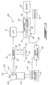
FIG. 1A is schematic view of a computerized system for bullet ballistic analysis based on 3D imaging in accordance with a first embodiment of the present invention; -
FIG. 1B is schematic view of a computerized system for spent cartridge case ballistic analysis based on 3D imaging in accordance with a second embodiment of the present invention; -
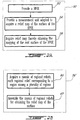
FIG. 2A is a flow chart of a surface mapping method of a bullet in accordance with one embodiment of the present invention; -
FIG. 2B is a flow chart detailing the steps of acquiring the relief map ofFIG. 2A , in the case where a mosaic of regional reliefs is acquired; -
FIG. 3 is a flow chart detailing the steps of acquiring a mosaic of regional reliefs ofFIG. 2B when a confocal microscope is used; -
FIG. 4 is a flow chart detailing the steps of measuring a series of light intensities ofFIG. 3 ; -
FIG. 5 is a flow chart for a method of acquiring and assembling a mosaic of overlapping reliefs in accordance with one embodiment of the present invention -
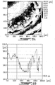
FIG. 6A is an example of a regional relief obtained with the surface mapping method of a bullet in accordance with one embodiment of the present invention; -
FIG. 6B is a sectional view taken along cross-section line A-A ofFIG.6A showing the striation structure; -
FIG. 7 is an example of a mosaic of overlapping reliefs, after they have been overlapped using the surface mapping method of a bullet in accordance with one embodiment of the present invention, -
FIG. 8A is an example of a regional relief obtained with the surface mapping method of a cartridge case in accordance with one embodiment; -
FIG. 8B is a sectional view taken along cross-section line A-A ofFIG. 8B showing the striation structure; -
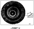
FIG. 9 is an example of a mosaic of overlapping reliefs, after they have been overlapped using the surface mapping method of a cartridge case in accordance with one embodiment of the present invention. - We will describe a system for mapping a surface of a BPOE. The system can be equally used to map a
bullet 12 or to map a spentcartridge case 112. - System for mapping a bullet surface: In a first embodiment of the present invention, a
computerized system 10 equipped with a confocal microscope is used to obtain a surface mapping of a bullet. This embodiment is illustrated inFIG.1A and can be described as follow. Thesystem 10 comprises as the main elements abullet holder 11 to hold abullet 12, aconfocal microscope sensor 16 to acquire a relief map of asurface 17 of thebullet 12, and a displacement system controlled by acomputer 22, to vary the relative position between thebullet 12 and the sensor 16 (longitudinally 33 or transversally 32). It is worth mentioning that although, in certain embodiments of the present invention, a confocal microscope is used as the mapping sensor, other sensors could also be used (Moiré, Laser Confocal Scanning Microscopy, Pixel Contrast). - In this first embodiment, the bullet holder can rotate the
bullet 12 about therotation axis 13 shown inFIG.1A , via amotor 14. Usingsensor 16, this rotation movement of thebullet 12 permits the measurement of contiguous regions of thebullet 12surface 17, to form later on a relief map of a peripheral band of thebullet 12. In this embodiment, a regional relief of a region of thebullet 12 is obtained, and then thebullet 12 is rotated by an angle to present another surface region, that will include a 50% overlap with the previous region, to the field of view of thesensor 16, and so on, until a complete peripheral band is measured. The exact angle of rotation is calculated and is inversely proportional to the bullet caliber. Obviously, other measurement configurations may also be implemented without departing from the scope of this invention. - In this first embodiment, the rotation of the
bullet 12 is controlled via thecontroller 24 which is itself linked to thecomputer 22. An encoder 27 measures the rotation angle of thebullet 12 and relays this information to the computer for further analysis. - The relative position between the
bullet 12 and thesensor 16 is changed by the micro-positioners 19 and 20. One micro-positioner 20 permits the variation of the height of thesensor 16 whereas theother micro-positioner 19 enables to vary the relative distance and tilt between thesensor 16 and thebullet 12. All micro-positioners 19, 20 are controlled by thecomputer 22 so that a series of measured intensities as a function of a series of distances may be obtained in a controlled manner, and that several such series may be obtained for several different regions of thebullet 12. - In this first embodiment, the
confocal microscope 16 comprises an analog todigital converter 21 which relays to thecomputer 22 the digitalized microscope measurements. Thecomputer 22 is used to control and adjust the parameters of thesensor 16 such as for example the focal distance of the microscope, its field of view, etc. In this first embodiment, thecomputerized system 10 also comprises adisplay unit 28 to visualize the measurements and the experiments parameters, and is also linked to adatabase 29 in which the measurements will be stored. Thedatabase 29 also gives access to measurements of other bullets for ballistic comparison studies. Ananalysis program 37 is used for processing the experimental data of thebullet 12 under examination and acomparison program 38 is used to compare thepresent bullet 12 relief map to other relief maps found in thedatabase 29. In a preferred embodiment, the methods of the present invention may be embodied incomputer 22. - System for mapping a cartridge case surface: In a second embodiment, a
system 110 similar tosystem 10 just described, is used to obtain a surface mapping of a spentcartridge case 112. This second embodiment is illustrated inFIG.1B . The main differences betweenFIG.1B andFIG.1A are related to the ways thecartridge case 112 is held and displaced bysystem 110 while acquiring the mosaic of relief regions. - In this second embodiment, the
cartridge case holder 111 can displace thecartridge case 112 about the X and Y axis shown inFIG.1B , via twomotors 14. Usingsensor 16, this displacement of thecartridge case 112 permits the measurement of contiguous regions of thecartridge case 112surface 117, to form later on a relief map of a composite region of thecartridge case 112. In this second embodiment, a regional relief of a region of thecartridge case 112 is obtained, and then thecartridge case 112 is displaced first in the X direction and then in the Y direction to present another surface region, that will include a 50% overlap with the previous region, to the field of view of thesensor 16, and so on until a complete array of regional reliefs, forming, when assembled, an image of the full head of thecartridge case 112, is obtained. The exact displacement is constant. Obviously, other measurement configurations may also be implemented without departing from the scope of this invention. - In this second embodiment, the rest of the
system 110 is the same as for thesystem 10, and therefore will not be further described. - A surface mapping method: We will now describe in detail a
method 50 of mapping a surface of a BPOE. The method applies equally well to abullet 12 or to acartridge case 112. - The main steps of a
surface mapping method 50 of a BPOE according to an embodiment of the present invention are listed inFIG. 2A and are described in more detail in the following paragraphs. - A BPOE under examination is provided at
step 52 and a measurement unit adapted to acquire a relief map of a surface of the BPOE is provided atstep 54. Then, atstep 56, the measurement unit acquires the relief map to thereby map the surface of the BPOE. In one embodiment, this surface is a peripheral band of abullet 12 corresponding to a surface region of thebullet 12 expected to containsignificant striations 23 produced when the firearm is fired. In another embodiment, this surface corresponds to a surface region of thecartridge case 112 expected to contain significantimpressed marks 23 produced when the firearm is fired. Often, but not exclusively, this surface region is located using a 2D-imaging technique, this permits examination of thebullet 12 or thecartridge case 112 prior to the 3D-imaging measurement, in order to identify what surface region of the BPOE contains the striations orimpressed marks 23 that should be analyzed with the present invention. In an embodiment, the previously describedcomputerized systems step 54. Thus according to themethod 50, a BPOE under examination is installed in thebullet holder 11 of the computerized system 10 (when the BPOE is a bullet) or in thecartridge case holder 111 of the computerized system 110 (when the BPOE is a cartridge case). Theinterface program 37 embedded in thecomputer 22 is used to program thesensor 16 measurement parameters, and to control the sensor displacements via the micro-positioners 19, 20. When the BPOE is abullet 12, thecomputer 22 also controls theholder rotating motor 14. The computer thus sends a signal to therotating motor 14 to rotate thebullet 12 until the surface, that has been chosen to be mapped, is in the field of view of thesensor 16, and theencoder 27 sends back a signal to inform the computer of the value of the measurement angle. Thecomputer 22 also sends signals to the micro-positioners 19, 20 to adjust the height of thesensor 16 relatively thebullet 12 via the micro-positioner 20, and a relative distance, d (not shown), between the bullet surface and thesensor 16 via themicro-positioner 19. When the BPOE is acartridge case 112, thecomputer 22 controls thetransversal displacement unit 113 that permits the displacement of the cartridge case head in the field of view of thesensor 16. The computer sends a signal totransversal displacement unit 113 to displace thecartridge case 112 until the surface, that has been chosen to be mapped, is in the field of view of thesensor 16, and theencoder 27 sends back a signal to inform the computer of the value of the measurement position. Thecomputer 22 also sends signals to the micro-positioners 19, 20 to adjust the height of thesensor 16 relative to thecartridge case 112 via the micro-positioner 20, and a relative distance, d (not shown), between the cartridge case surface and thesensor 16 via themicro-positioner 19. - Turning now to
FIG. 2B , in a preferred embodiment of step 56', a surface region of a BPOE susceptible to contain significant impressions and/orstriations 23 is mapped. When the BPOE is abullet 12, this surface region corresponds to a peripheral band of the bullet surface containingsignificant striations 23. When the BPOE is acartridge case 112, this surface corresponds to a full region of the cartridge case head surface containing significant impressions and/or striations. This mapping is performed by acquiring a mosaic of regional reliefs, each regional relief corresponding to a region among a plurality of regions (step 60), where the plurality of regions forms, in the case of a bullet, the peripheral band or forms, in the case of acartridge case 112, the full region of the cartridge case head surface. Then, atstep 67, this mosaic of regional reliefs is assembled for obtaining the relief map of the surface region of a BPOE under examination. This assembling is performed, for example, with theanalysis program 37 of thecomputer 22. - Now referring to
FIG. 3 , a flow chart details the step of acquiring a mosaic of regional reliefs fromFIG. 2B (step 60) when a confocal microscope is used as the measurement unit (step 54'). First, atstep 61, a region is selected among the plurality of regions that form the mosaic. Then, atstep 70, thesystem 10 makes a series of measurements with the confocal microscope to obtain a series of light intensities Id(x,y), corresponding to the selected region as a function of the variable distance d, where d is the distance separating a reference surface of the BPOE and the confocal microscope and where x and y are the surface coordinates of the selected region. Thisstep 70 comprises several intermediate steps that are detailed inFIG. 4 and will be described herein below. - When
step 70 is completed for the selected region, the regional relief z(x,y) 80 corresponding to the selected region is determined instep 63 using the well-known analysis principles of the confocal method. The result of this analysis is a regional relief map z(x,y) 80, where z is the depth value at the coordinates (x,y) of the selected region, and this result can be simply stored in thecomputer 22 for further analysis. - Then, steps 61, 70, and 63 are repeated until the regional reliefs of all the regions of the plurality of regions have been determined, therefore obtaining a complete mosaic of regional reliefs (step 67).
- Turning now to
FIG. 4 , the intermediate steps that are comprised instep 70 ofFIG. 3 are detailed. The goal is to measure with the confocal microscope the light intensity distribution, Id(x,y), for a series of different distances d, where x and y are the surface coordinates of the region under examination. A first distance is selected (step 71) via thecomputer 22, then thesensor 16 position is adjusted (step 73) accordingly via the micro-positioners 19. Then a first intensity distribution is acquired (step 75) with thesensor 16, digitized, and sent to thecomputer 22 for storage (step 77). These steps are repeated for all the distances of the series of distances, so that a complete series of light intensities is obtained (step 79). -
FIG. 6A is an example of aregional relief 80 of a bullet surface obtained with the surface mapping method just described, where anenlarged striation 23 can be seen. In this preferred embodiment, a regional relief corresponds to a physical area of 1.5mm X 1.5mm. The regional relief is mapped into an array of 512 x 512 pixels providing, in an exemplary embodiment, a lateral resolution of approximately 3 microns. Typical depth range of a regional relief depends on the bullet caliber, the firearm and the region. The biggest range would be found on a small caliber on the shoulder area and would be around 50 microns. The smallest range would be found on a .50 caliber in the middle of a groove engraved area and would be around 5 microns. The depth resolution of the sensor is, in an exemplary embodiment, 10 nanometres. Obviously, other physical characteristics of the regional relief can be obtained without departing from the scope of this invention, by tuning thesystem 10 differently. -
FIG. 6B is a sectional view taken along cross-section line A-A ofFIG. 6A showing the striation structure 93 along this cross-section line. It can be seen on this figure that this cross-section line possesses profile characteristics and features that can be used as a firearm identification signature. -
FIG. 8A is another example, this time of a regional relief 180 of a cartridge case obtained with the surface mapping method just described, where an impression and/orstriation 23 can be seen. A regional relief corresponds to a physical area of 1.5mm X 1.5mm. The regional relief is mapped into an array of 512 x 512 pixels providing a lateral resolution of approximately 3 microns. Typical depth range of a regional relief depends on the cartridge case caliber, the firearm and the region. The biggest range would be found on a large caliber on the firing ping impression area and would be around 250 microns. -
FIG. 8B is a sectional view taken along cross-section line AA ofFIG. 8A showing the impression and/or striation structure 93, which can be used, as already mentioned, as a firearm identification signature. - Turning now to
FIG. 5 , a preferred embodiment of themapping method 50 comprises acquiring a mosaic of overlapping reliefs 56', each overlapping relief corresponding to an overlapping region among a plurality of overlapping regions, wherein each overlapping relief has at least one overlapping area in common with an overlapping area of another overlapping relief (step 62). The advantage of acquiring overlapping reliefs (partly overlapping) is that they can be more easily aligned when comes the time to assemble them to form the final image of the BPOE. This assembling can be performed by finding the best overlapping degree between overlapping areas that are in common (step 64). - It is worth mentioning that the relief maps may suffer of distortions due, for example, to the curved surface of the bullet. The present invention provides an algorithm correcting these distortions effects in order to eliminate such distortion in the final assembling step. Also other distortion effects due to optical effects or due to misalignment measurement errors are also corrected via the algorithm provided by the present invention.
-
FIG. 7 gives an example of aperipheral band 100 of abullet 12 that was formed by a mosaic of aligned overlappingreliefs 88 where an exploded close-up of three consecutive overlapping reliefs of the mosaic is shown. As can be seen, each overlappingrelief 88 has at least one overlappingarea 89 in common with an overlappingarea 89 of another overlapping relief. In this example, the overlappingareas 89 are chosen such that each of the overlapping regions of this mosaic overlaps its neighbor regions by about 50 %. Naturally other overlapping degree could also vary without departing from the scope of this invention. -
FIG. 9 gives an example ofsurface array 200 of acartridge case 112 that was formed by a mosaic of aligned overlappingreliefs 88. As can be seen, each overlappingrelief 88 has at least one overlappingarea 89 in common with an overlappingarea 89 of another overlapping relief. In this example for a cartridge case head, the overlappingareas 89 are chosen such that each of the overlapping regions of this mosaic overlaps with its neighbor regions by about 50 %. Naturally other overlapping degree could also be varying without departing from the scope of this invention. - It will be understood that numerous modifications methods and apparatus described herein will appear to those skilled in the art. Accordingly, the above description and accompanying drawings should be taken as illustrative of the invention and not in a limiting sense.
Claims (23)
- A method of mapping a surface of a ballistic piece of evidence (BPOE), such that the mapping can be used as a 3-dimensional signature for identifying purposes during ballistic test comparison, wherein
said surface of the BPOE (9) comprises a plurality of regions, the method comprising:acquiring (63, 70) a plurality of z(x,y) regional reliefs (80, 180), where x and y are the surface coordinates of the region and z is the depth value at the coordinates (x,y) of the region, each z(x,y) regional relief corresponding to one of said plurality of regions, said acquiring comprising making a series of measurements (70) for obtaining a series of light intensities corresponding to the region as a function of a variable distance;eliminating from said z(x, y) regional reliefs distortions due to a curved surface of the BPOE;assembling (67) said plurality of regional reliefs into a mosaic for obtaining a relief map of said surface, thereby obtaining the 3-dimensionnal mapping of said surface of the BPOE. - The method as claimed in claim 1, further comprising selecting at least one region that is partly overlapping at least another region for thereby acquiring at least two overlapping reliefs, each having an overlapping area.
- The method as claimed in claim 2, further comprising aligning said at least two overlapping reliefs (88) such that said overlapping areas (89) cover a substantial portion of a total area of each one of said two overlapping reliefs.
- The method as claimed in claim 3, wherein said surface comprises a selected portion of the surface of said BPOE (9) thereby obtaining the mapping of a selected portion of the surface of said BPOE.
- The method as claimed in claim 4, wherein said acquiring a plurality of regional reliefs comprises measuring said regional reliefs with a confocal technique.
- The method as claimed in claim 5, wherein said acquiring comprises setting a position of the BPOE, prior to said measuring, to a measured position corresponding to one region among said plurality of regions.
- The method as claimed in claim 1, wherein said BPOE (9) comprises a bullet (12) and wherein said surface comprises a peripheral band on the bullet.
- The method as claimed in claim 7, wherein said setting a position of the bullet (12) to a measured position comprises calculating a rotation angle by which the bullet is rotated after a regional relief is acquired.
- The method as claimed in claim 7, wherein said acquiring comprises correcting distorting effects in regional reliefs to compensate for an off-axis rotation of the bullet.
- The method as claimed in claim 1, wherein said BPOE (9) comprises a cartridge case (112) and wherein said surface comprises a head of the cartridge.
- The method as claimed in claim 10, wherein said setting a position of the cartridge case (112) comprises calculating a transversal displacement by which the cartridge case is displaced after a regional relief is acquired.
- The method as claimed in claim 2, wherein said overlapping area (89) of an overlapping relief (88) represents approximately 50% of a surface of said overlapping relief.
- The method as claimed in claim 1, wherein said surface comprises a selected portion of the surface of said BPOE thereby obtaining the mapping of a selected portion of the surface of said BPOE.
- The method as claimed in claim 13, wherein said acquiring a plurality of regional reliefs comprises providing said BPOE (9).
- The method as claimed in claim 14, wherein said acquiring a plurality of regional reliefs comprises measuring said regional reliefs using a measurement unit adapted for said mapping.
- The method as claimed in claim 15, wherein said acquiring a plurality of regional reliefs comprises measuring said regional reliefs with a confocal technique.
- An apparatus for mapping a surface of a ballistic piece of evidence (BPOE), such that the mapping can be used as a 3-dimensional signature for identifying purposes during ballistic test comparison, said surface comprising a plurality of regions, the apparatus comprising:a holder for holding said BPOE (9);a measurement unit for acquiring a plurality of z(x,y) regional reliefs (80) where x and y are the surface coordinates of the region and z is the depth value at the coordinates (x,y) of the region, each z(x,y) regional relief corresponding to one of said plurality of regions, said acquiring comprising making a series of measurements (70) for obtaining a series of light intensities corresponding to the region as a function of a variable distance (d);a displacement unit (113) for providing a series of different measurement positions;a controller unit (24) to control said displacement unit; anda computer (22) adapted for calculating a three-dimensional mapping of said surface of the BPOE using the measurements by eliminating from said z(x, y) regional reliefs distortions due to a curved surface of the BPOE and assembling said plurality of regional reliefs into a mosaic for obtaining a relief map of said surface, thereby obtaining the 3-dimensionnal mapping of said surface of the BPOE.
- The apparatus as claimed in claim 17, wherein said measurement unit comprises a confocal microscope sensor (16).
- The apparatus as claimed in claim 17, wherein said displacement unit (113) comprises a longitudinal displacement unit for providing a series of relative distances between said BPOE and said confocal microscope sensor.
- The apparatus as claimed in claim 19, wherein said displacement unit (113) comprises a transversal displacement unit for displacing said BPOE in a plane.
- The apparatus as claimed in claim 20, wherein the controller unit controls said transversal displacement unit.
- The apparatus as claimed in claim 18, further comprising a storing unit receiving from the confocal microscope sensor measured regional 3D images and storing said measured regional 3D images as a function of corresponding measurement positions.
- The apparatus as claimed in claim 22, further comprising a 2D imaging system for acquiring a 2D image of each region of said surface of the BPOE, and providing said user with a two-dimensional light intensity image as complementary information to said relief map of said surface, said two-dimensional light intensity image having been acquired with a same set of x,y coordinates as said plurality of regional reliefs.
Applications Claiming Priority (2)
| Application Number | Priority Date | Filing Date | Title |
|---|---|---|---|
| US10/913,508 US7796810B2 (en) | 2004-05-03 | 2004-08-09 | 3D bullet and cartridge case analysis |
| PCT/CA2005/001200 WO2006015475A1 (en) | 2004-08-09 | 2005-08-02 | 3d bullet and cartridge case analysis |
Publications (3)
| Publication Number | Publication Date |
|---|---|
| EP1776557A1 EP1776557A1 (en) | 2007-04-25 |
| EP1776557A4 EP1776557A4 (en) | 2012-10-31 |
| EP1776557B1 true EP1776557B1 (en) | 2017-03-22 |
Family
ID=35839094
Family Applications (1)
| Application Number | Title | Priority Date | Filing Date |
|---|---|---|---|
| EP05772134.2A Expired - Lifetime EP1776557B1 (en) | 2004-08-09 | 2005-08-02 | 3d bullet and cartridge case analysis |
Country Status (7)
| Country | Link |
|---|---|
| US (1) | US7796810B2 (en) |
| EP (1) | EP1776557B1 (en) |
| AU (1) | AU2005270687B9 (en) |
| CA (1) | CA2574824C (en) |
| MX (1) | MX2007001651A (en) |
| WO (1) | WO2006015475A1 (en) |
| ZA (1) | ZA200700990B (en) |
Cited By (1)
| Publication number | Priority date | Publication date | Assignee | Title |
|---|---|---|---|---|
| WO2021096476A1 (en) | 2019-11-15 | 2021-05-20 | Derya Vural | Topographical ballistic identification with section profiles and comparison system |
Families Citing this family (8)
| Publication number | Priority date | Publication date | Assignee | Title |
|---|---|---|---|---|
| CN1917893A (en) * | 2004-02-09 | 2007-02-21 | 美国泛华医药公司 | Methods for isolation of triptolide compounds from tripterygium wilfordii |
| TR200802780A2 (en) | 2008-04-22 | 2009-11-23 | T�B�Tak- T�Rk�Ye B�L�Msel Ve Teknoloj�K Ara�Tirma Kurumu | Automatic zone segmentation on barrel bottom table and selection of optimal track area for barrel comparison. |
| GB0811985D0 (en) * | 2008-07-01 | 2008-07-30 | Univ Huddersfield | Surface analysis apparatus and method |
| CN101539389B (en) * | 2009-04-13 | 2012-05-30 | 马建春 | Positioning method for keeping uniform standard of measurement attitude of warhead surface trace |
| US8817016B2 (en) | 2010-04-08 | 2014-08-26 | Forensic Technology Wai, Inc. | Generation of a modified 3D image of an object comprising tool marks |
| JP6221187B2 (en) * | 2012-11-16 | 2017-11-01 | トゥビタク | Bullet holder system for ballistic analysis |
| CN105651208B (en) * | 2016-03-28 | 2018-11-02 | 东莞成电术有精密技术有限公司 | Bullet and cartridge case coaxiality optical measuring instrument and measuring method |
| CN109115111B (en) * | 2018-09-19 | 2020-07-14 | 中国计量科学研究院 | Accuracy evaluation method of three-dimensional warhead trace measuring instrument |
Family Cites Families (4)
| Publication number | Priority date | Publication date | Assignee | Title |
|---|---|---|---|---|
| US5390108A (en) * | 1991-05-24 | 1995-02-14 | Forensic Technology Wai Inc. | Computer automated bullet analysis apparatus |
| CA2207454C (en) | 1995-01-03 | 2000-08-01 | Forensic Technology Wai Inc. | Fired cartridge examination method and imaging apparatus |
| JP3403875B2 (en) * | 1995-10-16 | 2003-05-06 | 大日本スクリーン製造株式会社 | Three-dimensional measurement method and display method, and three-dimensional measurement device |
| US6505140B1 (en) * | 2000-01-18 | 2003-01-07 | Intelligent Automation, Inc. | Computerized system and method for bullet ballistic analysis |
-
2004
- 2004-08-09 US US10/913,508 patent/US7796810B2/en active Active
-
2005
- 2005-08-02 WO PCT/CA2005/001200 patent/WO2006015475A1/en not_active Ceased
- 2005-08-02 AU AU2005270687A patent/AU2005270687B9/en not_active Expired
- 2005-08-02 CA CA2574824A patent/CA2574824C/en not_active Expired - Lifetime
- 2005-08-02 EP EP05772134.2A patent/EP1776557B1/en not_active Expired - Lifetime
- 2005-08-02 MX MX2007001651A patent/MX2007001651A/en active IP Right Grant
-
2007
- 2007-02-02 ZA ZA200700990A patent/ZA200700990B/en unknown
Cited By (1)
| Publication number | Priority date | Publication date | Assignee | Title |
|---|---|---|---|---|
| WO2021096476A1 (en) | 2019-11-15 | 2021-05-20 | Derya Vural | Topographical ballistic identification with section profiles and comparison system |
Also Published As
| Publication number | Publication date |
|---|---|
| CA2574824C (en) | 2011-03-15 |
| US20050244080A1 (en) | 2005-11-03 |
| AU2005270687B2 (en) | 2010-10-21 |
| ZA200700990B (en) | 2008-04-30 |
| MX2007001651A (en) | 2007-04-24 |
| AU2005270687B9 (en) | 2011-03-03 |
| CA2574824A1 (en) | 2006-02-16 |
| US7796810B2 (en) | 2010-09-14 |
| WO2006015475A1 (en) | 2006-02-16 |
| AU2005270687A1 (en) | 2006-02-16 |
| EP1776557A1 (en) | 2007-04-25 |
| EP1776557A4 (en) | 2012-10-31 |
Similar Documents
| Publication | Publication Date | Title |
|---|---|---|
| ZA200700990B (en) | 3D bullet and cartridge case analysis | |
| KR101194936B1 (en) | Three-dimensional measurement apparatus and method thereof | |
| EP3306266B1 (en) | Three-dimensional shape measurement apparatus | |
| US8340356B2 (en) | Method for producing a known fixed spatial relationship between a laser scanner and a digital camera for traffic monitoring | |
| CN109186491A (en) | Parallel multi-thread laser measurement system and measurement method based on homography matrix | |
| CN112465912A (en) | Three-dimensional camera calibration method and device | |
| CN107543496B (en) | A kind of binocular stereo vision three-dimensional coordinate measurement method | |
| CA2577840C (en) | A method for automated 3d imaging | |
| CN107358628B (en) | Linear array image processing method based on target | |
| EP2574876A1 (en) | Method and device for determining the 3D coordinates of an object | |
| JP5051493B2 (en) | 3D measurement marker and 3D measurement method using the same | |
| US6505140B1 (en) | Computerized system and method for bullet ballistic analysis | |
| US20120300065A1 (en) | Optical device for measuring and identifying cylindrical surfaces by deflectometry applied to ballistic identification | |
| US6064760A (en) | Method for rigorous reshaping of stereo imagery with digital photogrammetric workstation | |
| EP2382585B1 (en) | Surface analysis apparatus and method | |
| CN115880424A (en) | Three-dimensional reconstruction method and device, electronic equipment and machine-readable storage medium | |
| US5633717A (en) | Method for monitoring and adjusting the position of an object under optical observation for imaging | |
| CA3158279A1 (en) | Topographical ballistic identification with section profiles and comparison system | |
| Smith et al. | Line-scan imaging for the positive identification of ballistics specimens | |
| Makrushin et al. | 3D imaging for ballistics analysis using chromatic white light sensor | |
| Smith et al. | Intelligent imaging of forensic ballistics specimens for ID | |
| Singh et al. | Digital photogrammetry for automatic close range measurement of textureless and featureless objects | |
| Kassamakov et al. | CSI Helsinki: Comparing three-dimensional imaging of diagonal cutter toolmarks using confocal microscopy and SWLI | |
| Kühmstedt et al. | Multi-resolution optical 3D sensor | |
| WO2025082557A1 (en) | Method of measuring deformations by means of optical extensometer |
Legal Events
| Date | Code | Title | Description |
|---|---|---|---|
| PUAI | Public reference made under article 153(3) epc to a published international application that has entered the european phase |
Free format text: ORIGINAL CODE: 0009012 |
|
| 17P | Request for examination filed |
Effective date: 20070131 |
|
| AK | Designated contracting states |
Kind code of ref document: A1 Designated state(s): AT BE BG CH CY CZ DE DK EE ES FI FR GB GR HU IE IS IT LI LT LU LV MC NL PL PT RO SE SI SK TR |
|
| DAX | Request for extension of the european patent (deleted) | ||
| A4 | Supplementary search report drawn up and despatched |
Effective date: 20120927 |
|
| RIC1 | Information provided on ipc code assigned before grant |
Ipc: G01B 11/24 20060101AFI20120921BHEP Ipc: G01N 21/84 20060101ALI20120921BHEP |
|
| RAP1 | Party data changed (applicant data changed or rights of an application transferred) |
Owner name: ULTRA ELECTRONICS FORENSIC TECHNOLOGY INC. |
|
| GRAP | Despatch of communication of intention to grant a patent |
Free format text: ORIGINAL CODE: EPIDOSNIGR1 |
|
| INTG | Intention to grant announced |
Effective date: 20160520 |
|
| GRAJ | Information related to disapproval of communication of intention to grant by the applicant or resumption of examination proceedings by the epo deleted |
Free format text: ORIGINAL CODE: EPIDOSDIGR1 |
|
| GRAP | Despatch of communication of intention to grant a patent |
Free format text: ORIGINAL CODE: EPIDOSNIGR1 |
|
| INTC | Intention to grant announced (deleted) | ||
| INTG | Intention to grant announced |
Effective date: 20161017 |
|
| GRAS | Grant fee paid |
Free format text: ORIGINAL CODE: EPIDOSNIGR3 |
|
| GRAA | (expected) grant |
Free format text: ORIGINAL CODE: 0009210 |
|
| AK | Designated contracting states |
Kind code of ref document: B1 Designated state(s): AT BE BG CH CY CZ DE DK EE ES FI FR GB GR HU IE IS IT LI LT LU LV MC NL PL PT RO SE SI SK TR |
|
| REG | Reference to a national code |
Ref country code: GB Ref legal event code: FG4D |
|
| REG | Reference to a national code |
Ref country code: CH Ref legal event code: EP |
|
| REG | Reference to a national code |
Ref country code: AT Ref legal event code: REF Ref document number: 878225 Country of ref document: AT Kind code of ref document: T Effective date: 20170415 |
|
| REG | Reference to a national code |
Ref country code: IE Ref legal event code: FG4D |
|
| REG | Reference to a national code |
Ref country code: DE Ref legal event code: R096 Ref document number: 602005051585 Country of ref document: DE |
|
| REG | Reference to a national code |
Ref country code: NL Ref legal event code: MP Effective date: 20170322 |
|
| PG25 | Lapsed in a contracting state [announced via postgrant information from national office to epo] |
Ref country code: GR Free format text: LAPSE BECAUSE OF FAILURE TO SUBMIT A TRANSLATION OF THE DESCRIPTION OR TO PAY THE FEE WITHIN THE PRESCRIBED TIME-LIMIT Effective date: 20170623 Ref country code: FI Free format text: LAPSE BECAUSE OF FAILURE TO SUBMIT A TRANSLATION OF THE DESCRIPTION OR TO PAY THE FEE WITHIN THE PRESCRIBED TIME-LIMIT Effective date: 20170322 Ref country code: LT Free format text: LAPSE BECAUSE OF FAILURE TO SUBMIT A TRANSLATION OF THE DESCRIPTION OR TO PAY THE FEE WITHIN THE PRESCRIBED TIME-LIMIT Effective date: 20170322 |
|
| REG | Reference to a national code |
Ref country code: LT Ref legal event code: MG4D |
|
| REG | Reference to a national code |
Ref country code: AT Ref legal event code: MK05 Ref document number: 878225 Country of ref document: AT Kind code of ref document: T Effective date: 20170322 |
|
| REG | Reference to a national code |
Ref country code: FR Ref legal event code: PLFP Year of fee payment: 13 |
|
| PG25 | Lapsed in a contracting state [announced via postgrant information from national office to epo] |
Ref country code: BG Free format text: LAPSE BECAUSE OF FAILURE TO SUBMIT A TRANSLATION OF THE DESCRIPTION OR TO PAY THE FEE WITHIN THE PRESCRIBED TIME-LIMIT Effective date: 20170622 Ref country code: SE Free format text: LAPSE BECAUSE OF FAILURE TO SUBMIT A TRANSLATION OF THE DESCRIPTION OR TO PAY THE FEE WITHIN THE PRESCRIBED TIME-LIMIT Effective date: 20170322 Ref country code: LV Free format text: LAPSE BECAUSE OF FAILURE TO SUBMIT A TRANSLATION OF THE DESCRIPTION OR TO PAY THE FEE WITHIN THE PRESCRIBED TIME-LIMIT Effective date: 20170322 |
|
| PG25 | Lapsed in a contracting state [announced via postgrant information from national office to epo] |
Ref country code: NL Free format text: LAPSE BECAUSE OF FAILURE TO SUBMIT A TRANSLATION OF THE DESCRIPTION OR TO PAY THE FEE WITHIN THE PRESCRIBED TIME-LIMIT Effective date: 20170322 |
|
| PG25 | Lapsed in a contracting state [announced via postgrant information from national office to epo] |
Ref country code: IT Free format text: LAPSE BECAUSE OF FAILURE TO SUBMIT A TRANSLATION OF THE DESCRIPTION OR TO PAY THE FEE WITHIN THE PRESCRIBED TIME-LIMIT Effective date: 20170322 Ref country code: SK Free format text: LAPSE BECAUSE OF FAILURE TO SUBMIT A TRANSLATION OF THE DESCRIPTION OR TO PAY THE FEE WITHIN THE PRESCRIBED TIME-LIMIT Effective date: 20170322 Ref country code: AT Free format text: LAPSE BECAUSE OF FAILURE TO SUBMIT A TRANSLATION OF THE DESCRIPTION OR TO PAY THE FEE WITHIN THE PRESCRIBED TIME-LIMIT Effective date: 20170322 Ref country code: EE Free format text: LAPSE BECAUSE OF FAILURE TO SUBMIT A TRANSLATION OF THE DESCRIPTION OR TO PAY THE FEE WITHIN THE PRESCRIBED TIME-LIMIT Effective date: 20170322 Ref country code: ES Free format text: LAPSE BECAUSE OF FAILURE TO SUBMIT A TRANSLATION OF THE DESCRIPTION OR TO PAY THE FEE WITHIN THE PRESCRIBED TIME-LIMIT Effective date: 20170322 Ref country code: RO Free format text: LAPSE BECAUSE OF FAILURE TO SUBMIT A TRANSLATION OF THE DESCRIPTION OR TO PAY THE FEE WITHIN THE PRESCRIBED TIME-LIMIT Effective date: 20170322 |
|
| PG25 | Lapsed in a contracting state [announced via postgrant information from national office to epo] |
Ref country code: PT Free format text: LAPSE BECAUSE OF FAILURE TO SUBMIT A TRANSLATION OF THE DESCRIPTION OR TO PAY THE FEE WITHIN THE PRESCRIBED TIME-LIMIT Effective date: 20170724 Ref country code: IS Free format text: LAPSE BECAUSE OF FAILURE TO SUBMIT A TRANSLATION OF THE DESCRIPTION OR TO PAY THE FEE WITHIN THE PRESCRIBED TIME-LIMIT Effective date: 20170722 Ref country code: PL Free format text: LAPSE BECAUSE OF FAILURE TO SUBMIT A TRANSLATION OF THE DESCRIPTION OR TO PAY THE FEE WITHIN THE PRESCRIBED TIME-LIMIT Effective date: 20170322 |
|
| REG | Reference to a national code |
Ref country code: DE Ref legal event code: R097 Ref document number: 602005051585 Country of ref document: DE |
|
| PLBE | No opposition filed within time limit |
Free format text: ORIGINAL CODE: 0009261 |
|
| STAA | Information on the status of an ep patent application or granted ep patent |
Free format text: STATUS: NO OPPOSITION FILED WITHIN TIME LIMIT |
|
| PG25 | Lapsed in a contracting state [announced via postgrant information from national office to epo] |
Ref country code: DK Free format text: LAPSE BECAUSE OF FAILURE TO SUBMIT A TRANSLATION OF THE DESCRIPTION OR TO PAY THE FEE WITHIN THE PRESCRIBED TIME-LIMIT Effective date: 20170322 |
|
| 26N | No opposition filed |
Effective date: 20180102 |
|
| PG25 | Lapsed in a contracting state [announced via postgrant information from national office to epo] |
Ref country code: SI Free format text: LAPSE BECAUSE OF FAILURE TO SUBMIT A TRANSLATION OF THE DESCRIPTION OR TO PAY THE FEE WITHIN THE PRESCRIBED TIME-LIMIT Effective date: 20170322 |
|
| REG | Reference to a national code |
Ref country code: CH Ref legal event code: PL |
|
| PG25 | Lapsed in a contracting state [announced via postgrant information from national office to epo] |
Ref country code: MC Free format text: LAPSE BECAUSE OF FAILURE TO SUBMIT A TRANSLATION OF THE DESCRIPTION OR TO PAY THE FEE WITHIN THE PRESCRIBED TIME-LIMIT Effective date: 20170322 |
|
| PG25 | Lapsed in a contracting state [announced via postgrant information from national office to epo] |
Ref country code: CH Free format text: LAPSE BECAUSE OF NON-PAYMENT OF DUE FEES Effective date: 20170831 Ref country code: LI Free format text: LAPSE BECAUSE OF NON-PAYMENT OF DUE FEES Effective date: 20170831 |
|
| PG25 | Lapsed in a contracting state [announced via postgrant information from national office to epo] |
Ref country code: LU Free format text: LAPSE BECAUSE OF NON-PAYMENT OF DUE FEES Effective date: 20170802 |
|
| REG | Reference to a national code |
Ref country code: FR Ref legal event code: PLFP Year of fee payment: 14 |
|
| PG25 | Lapsed in a contracting state [announced via postgrant information from national office to epo] |
Ref country code: HU Free format text: LAPSE BECAUSE OF FAILURE TO SUBMIT A TRANSLATION OF THE DESCRIPTION OR TO PAY THE FEE WITHIN THE PRESCRIBED TIME-LIMIT; INVALID AB INITIO Effective date: 20050802 |
|
| PG25 | Lapsed in a contracting state [announced via postgrant information from national office to epo] |
Ref country code: CY Free format text: LAPSE BECAUSE OF NON-PAYMENT OF DUE FEES Effective date: 20170322 |
|
| PGFP | Annual fee paid to national office [announced via postgrant information from national office to epo] |
Ref country code: BE Payment date: 20220718 Year of fee payment: 18 |
|
| REG | Reference to a national code |
Ref country code: BE Ref legal event code: MM Effective date: 20230831 |
|
| PG25 | Lapsed in a contracting state [announced via postgrant information from national office to epo] |
Ref country code: BE Free format text: LAPSE BECAUSE OF NON-PAYMENT OF DUE FEES Effective date: 20230831 |
|
| PGFP | Annual fee paid to national office [announced via postgrant information from national office to epo] |
Ref country code: IE Payment date: 20240723 Year of fee payment: 20 Ref country code: DE Payment date: 20240723 Year of fee payment: 20 |
|
| PGFP | Annual fee paid to national office [announced via postgrant information from national office to epo] |
Ref country code: GB Payment date: 20240725 Year of fee payment: 20 |
|
| PGFP | Annual fee paid to national office [announced via postgrant information from national office to epo] |
Ref country code: FR Payment date: 20240726 Year of fee payment: 20 |
|
| PGFP | Annual fee paid to national office [announced via postgrant information from national office to epo] |
Ref country code: CZ Payment date: 20240726 Year of fee payment: 20 |
|
| PGFP | Annual fee paid to national office [announced via postgrant information from national office to epo] |
Ref country code: TR Payment date: 20240730 Year of fee payment: 20 |
|
| REG | Reference to a national code |
Ref country code: DE Ref legal event code: R071 Ref document number: 602005051585 Country of ref document: DE |
|
| REG | Reference to a national code |
Ref country code: GB Ref legal event code: PE20 Expiry date: 20250801 |
|
| REG | Reference to a national code |
Ref country code: IE Ref legal event code: MK9A |
|
| PG25 | Lapsed in a contracting state [announced via postgrant information from national office to epo] |
Ref country code: CZ Free format text: LAPSE BECAUSE OF EXPIRATION OF PROTECTION Effective date: 20250802 Ref country code: IE Free format text: LAPSE BECAUSE OF EXPIRATION OF PROTECTION Effective date: 20250802 |