EP1775955A2 - Control of a scene structure of multiple channels to be displayed on a mobile terminal - Google Patents
Control of a scene structure of multiple channels to be displayed on a mobile terminal Download PDFInfo
- Publication number
- EP1775955A2 EP1775955A2 EP06021651A EP06021651A EP1775955A2 EP 1775955 A2 EP1775955 A2 EP 1775955A2 EP 06021651 A EP06021651 A EP 06021651A EP 06021651 A EP06021651 A EP 06021651A EP 1775955 A2 EP1775955 A2 EP 1775955A2
- Authority
- EP
- European Patent Office
- Prior art keywords
- media
- channel
- logical channel
- field
- stream
- Prior art date
- Legal status (The legal status is an assumption and is not a legal conclusion. Google has not performed a legal analysis and makes no representation as to the accuracy of the status listed.)
- Withdrawn
Links
Images






Classifications
-
- H—ELECTRICITY
- H04—ELECTRIC COMMUNICATION TECHNIQUE
- H04N—PICTORIAL COMMUNICATION, e.g. TELEVISION
- H04N19/00—Methods or arrangements for coding, decoding, compressing or decompressing digital video signals
- H04N19/60—Methods or arrangements for coding, decoding, compressing or decompressing digital video signals using transform coding
- H04N19/61—Methods or arrangements for coding, decoding, compressing or decompressing digital video signals using transform coding in combination with predictive coding
-
- A—HUMAN NECESSITIES
- A23—FOODS OR FOODSTUFFS; TREATMENT THEREOF, NOT COVERED BY OTHER CLASSES
- A23L—FOODS, FOODSTUFFS OR NON-ALCOHOLIC BEVERAGES, NOT OTHERWISE PROVIDED FOR; PREPARATION OR TREATMENT THEREOF
- A23L17/00—Food-from-the-sea products; Fish products; Fish meal; Fish-egg substitutes; Preparation or treatment thereof
- A23L17/75—Coating with a layer, stuffing, laminating, binding or compressing of original fish pieces
-
- A—HUMAN NECESSITIES
- A23—FOODS OR FOODSTUFFS; TREATMENT THEREOF, NOT COVERED BY OTHER CLASSES
- A23B—PRESERVATION OF FOODS, FOODSTUFFS OR NON-ALCOHOLIC BEVERAGES; CHEMICAL RIPENING OF FRUIT OR VEGETABLES
- A23B2/00—Preservation of foods or foodstuffs, in general
- A23B2/90—Preservation of foods or foodstuffs, in general by drying or kilning; Subsequent reconstitution
-
- H—ELECTRICITY
- H04—ELECTRIC COMMUNICATION TECHNIQUE
- H04N—PICTORIAL COMMUNICATION, e.g. TELEVISION
- H04N21/00—Selective content distribution, e.g. interactive television or video on demand [VOD]
- H04N21/20—Servers specifically adapted for the distribution of content, e.g. VOD servers; Operations thereof
- H04N21/23—Processing of content or additional data; Elementary server operations; Server middleware
- H04N21/234—Processing of video elementary streams, e.g. splicing of video streams or manipulating encoded video stream scene graphs
- H04N21/23412—Processing of video elementary streams, e.g. splicing of video streams or manipulating encoded video stream scene graphs for generating or manipulating the scene composition of objects, e.g. MPEG-4 objects
-
- H—ELECTRICITY
- H04—ELECTRIC COMMUNICATION TECHNIQUE
- H04N—PICTORIAL COMMUNICATION, e.g. TELEVISION
- H04N21/00—Selective content distribution, e.g. interactive television or video on demand [VOD]
- H04N21/20—Servers specifically adapted for the distribution of content, e.g. VOD servers; Operations thereof
- H04N21/23—Processing of content or additional data; Elementary server operations; Server middleware
- H04N21/234—Processing of video elementary streams, e.g. splicing of video streams or manipulating encoded video stream scene graphs
- H04N21/2343—Processing of video elementary streams, e.g. splicing of video streams or manipulating encoded video stream scene graphs involving reformatting operations of video signals for distribution or compliance with end-user requests or end-user device requirements
- H04N21/234318—Processing of video elementary streams, e.g. splicing of video streams or manipulating encoded video stream scene graphs involving reformatting operations of video signals for distribution or compliance with end-user requests or end-user device requirements by decomposing into objects, e.g. MPEG-4 objects
-
- H—ELECTRICITY
- H04—ELECTRIC COMMUNICATION TECHNIQUE
- H04N—PICTORIAL COMMUNICATION, e.g. TELEVISION
- H04N21/00—Selective content distribution, e.g. interactive television or video on demand [VOD]
- H04N21/20—Servers specifically adapted for the distribution of content, e.g. VOD servers; Operations thereof
- H04N21/23—Processing of content or additional data; Elementary server operations; Server middleware
- H04N21/235—Processing of additional data, e.g. scrambling of additional data or processing content descriptors
-
- H—ELECTRICITY
- H04—ELECTRIC COMMUNICATION TECHNIQUE
- H04N—PICTORIAL COMMUNICATION, e.g. TELEVISION
- H04N21/00—Selective content distribution, e.g. interactive television or video on demand [VOD]
- H04N21/40—Client devices specifically adapted for the reception of or interaction with content, e.g. set-top-box [STB]; Operations thereof
- H04N21/41—Structure of client; Structure of client peripherals
- H04N21/414—Specialised client platforms, e.g. receiver in car or embedded in a mobile appliance
- H04N21/41407—Specialised client platforms, e.g. receiver in car or embedded in a mobile appliance embedded in a portable device, e.g. video client on a mobile phone, PDA, laptop
-
- H—ELECTRICITY
- H04—ELECTRIC COMMUNICATION TECHNIQUE
- H04N—PICTORIAL COMMUNICATION, e.g. TELEVISION
- H04N21/00—Selective content distribution, e.g. interactive television or video on demand [VOD]
- H04N21/40—Client devices specifically adapted for the reception of or interaction with content, e.g. set-top-box [STB]; Operations thereof
- H04N21/43—Processing of content or additional data, e.g. demultiplexing additional data from a digital video stream; Elementary client operations, e.g. monitoring of home network or synchronising decoder's clock; Client middleware
- H04N21/4302—Content synchronisation processes, e.g. decoder synchronisation
- H04N21/4307—Synchronising the rendering of multiple content streams or additional data on devices, e.g. synchronisation of audio on a mobile phone with the video output on the TV screen
- H04N21/43074—Synchronising the rendering of multiple content streams or additional data on devices, e.g. synchronisation of audio on a mobile phone with the video output on the TV screen of additional data with content streams on the same device, e.g. of EPG data or interactive icon with a TV programme
-
- H—ELECTRICITY
- H04—ELECTRIC COMMUNICATION TECHNIQUE
- H04N—PICTORIAL COMMUNICATION, e.g. TELEVISION
- H04N21/00—Selective content distribution, e.g. interactive television or video on demand [VOD]
- H04N21/40—Client devices specifically adapted for the reception of or interaction with content, e.g. set-top-box [STB]; Operations thereof
- H04N21/43—Processing of content or additional data, e.g. demultiplexing additional data from a digital video stream; Elementary client operations, e.g. monitoring of home network or synchronising decoder's clock; Client middleware
- H04N21/431—Generation of visual interfaces for content selection or interaction; Content or additional data rendering
- H04N21/4312—Generation of visual interfaces for content selection or interaction; Content or additional data rendering involving specific graphical features, e.g. screen layout, special fonts or colors, blinking icons, highlights or animations
- H04N21/4316—Generation of visual interfaces for content selection or interaction; Content or additional data rendering involving specific graphical features, e.g. screen layout, special fonts or colors, blinking icons, highlights or animations for displaying supplemental content in a region of the screen, e.g. an advertisement in a separate window
-
- H—ELECTRICITY
- H04—ELECTRIC COMMUNICATION TECHNIQUE
- H04N—PICTORIAL COMMUNICATION, e.g. TELEVISION
- H04N21/00—Selective content distribution, e.g. interactive television or video on demand [VOD]
- H04N21/40—Client devices specifically adapted for the reception of or interaction with content, e.g. set-top-box [STB]; Operations thereof
- H04N21/43—Processing of content or additional data, e.g. demultiplexing additional data from a digital video stream; Elementary client operations, e.g. monitoring of home network or synchronising decoder's clock; Client middleware
- H04N21/435—Processing of additional data, e.g. decrypting of additional data, reconstructing software from modules extracted from the transport stream
-
- H—ELECTRICITY
- H04—ELECTRIC COMMUNICATION TECHNIQUE
- H04N—PICTORIAL COMMUNICATION, e.g. TELEVISION
- H04N21/00—Selective content distribution, e.g. interactive television or video on demand [VOD]
- H04N21/40—Client devices specifically adapted for the reception of or interaction with content, e.g. set-top-box [STB]; Operations thereof
- H04N21/43—Processing of content or additional data, e.g. demultiplexing additional data from a digital video stream; Elementary client operations, e.g. monitoring of home network or synchronising decoder's clock; Client middleware
- H04N21/44—Processing of video elementary streams, e.g. splicing a video clip retrieved from local storage with an incoming video stream or rendering scenes according to encoded video stream scene graphs
- H04N21/44012—Processing of video elementary streams, e.g. splicing a video clip retrieved from local storage with an incoming video stream or rendering scenes according to encoded video stream scene graphs involving rendering scenes according to scene graphs, e.g. MPEG-4 scene graphs
-
- H—ELECTRICITY
- H04—ELECTRIC COMMUNICATION TECHNIQUE
- H04N—PICTORIAL COMMUNICATION, e.g. TELEVISION
- H04N21/00—Selective content distribution, e.g. interactive television or video on demand [VOD]
- H04N21/80—Generation or processing of content or additional data by content creator independently of the distribution process; Content per se
- H04N21/85—Assembly of content; Generation of multimedia applications
- H04N21/854—Content authoring
- H04N21/8543—Content authoring using a description language, e.g. Multimedia and Hypermedia information coding Expert Group [MHEG], eXtensible Markup Language [XML]
-
- A—HUMAN NECESSITIES
- A23—FOODS OR FOODSTUFFS; TREATMENT THEREOF, NOT COVERED BY OTHER CLASSES
- A23V—INDEXING SCHEME RELATING TO FOODS, FOODSTUFFS OR NON-ALCOHOLIC BEVERAGES AND LACTIC OR PROPIONIC ACID BACTERIA USED IN FOODSTUFFS OR FOOD PREPARATION
- A23V2002/00—Food compositions, function of food ingredients or processes for food or foodstuffs
-
- A—HUMAN NECESSITIES
- A23—FOODS OR FOODSTUFFS; TREATMENT THEREOF, NOT COVERED BY OTHER CLASSES
- A23V—INDEXING SCHEME RELATING TO FOODS, FOODSTUFFS OR NON-ALCOHOLIC BEVERAGES AND LACTIC OR PROPIONIC ACID BACTERIA USED IN FOODSTUFFS OR FOOD PREPARATION
- A23V2300/00—Processes
- A23V2300/10—Drying, dehydrating
Definitions
- the present invention generally relates to a display technology of a mobile terminal in a mobile broadcast system. More particularly, the present invention relates to a method, apparatus and system for controlling a scene structure of a mobile terminal for receiving and displaying data streams in a mobile broadcast system.
- LASeR Lightweight Application Scene Representation
- MPEG-4 BIFS Moving Picture Experts Group-4 Binary Format for Scene
- the BIFS is the scene description standard for all multimedia contents
- the LASeR is the scene description standard for multimedia terminals such as mobile phones small display sizes and a reduced network bandwidth.
- the BIFS is used for an object-based system.
- multimedia is a set of objects.
- Temporal and spatial information of each of the media must be indicated.
- four objects such as a weather caster, a weather chart displayed behind the weather caster, speech of the weather caster, and background music can be considered.
- an appearing time, disappearing time and position of each object should be defined to describe one scene. This definition is the BIFS. Because related information is stored in a binary file according to the BIFS, the storage capacity is reduced.
- the BIFS has a large amount of data of about 200 pages as described in the MPEG-4 system standard document (International Organization for Standardization/International Electro-technical Commission (ISO/IEC) 14496-1). It is difficult to use the BIFS in communication environments suffering from a shortage of available resources, such as in mobile terminals.
- An alternative plan is the LASeR.
- the LASeR is the technology developed for free representations of various multimedia and interactions with users in mobile terminals with limited memory and power by performing multiplexing and synchronization processes for different elementary streams (ESs) such as a scene description, video, audio, media, font, and metadata, and minimizing complexity.
- ESs elementary streams
- the ESs have the above-described generic meaning.
- the ESs are considered to be individual logical channels configuring multiple channels to be displayed.
- the LASeR ES is constructed with an access unit (AU) including a command.
- the command is used to change the scene characteristic at a particular time.
- Simultaneous commands are grouped in one AU.
- the AU may be one scene media, short sound, one graphic media, or short animation.
- a LASeR browser displays ESs in a designated order. The hierarchy is present between the ESs.
- the LASeR browser displays scenes in order of: (1) packet reception, (2) packet decoding (AU-by-AU recovery of one media and one video clip, among others), (3) command execution, (4) audio/video object rendering, (5) user interaction (selection and dragging, among others), and (6) local connection or connection with an external information source.
- the standardization for the convergence of the LASeR and World Wide Web Consortium is ongoing.
- SVG World Wide Web Consortium
- the conventional LASeR technology has been proposed only to compose a movie tile using a clip path of SVG 1.1 such that a channel mosaic service for multiple channels is provided.
- Using the LASeR technology in a mobile terminal creates a problem in identifying channel stream content in service when a screen media of the mobile terminal is tiled.
- Using the LASeR technology in a mobile terminal facilitates the display of channels because a screen size of the mobile terminal is smaller than those of terminal and personal computer (PC) systems for receiving existing broadcast services.
- PC personal computer
- the currently proposed stream source technology for composing a multi-channel media displays multiple broadcast service channels on one screen by multiplexing multiple medias into one channel for the channel mosaic service and allocating an additional encoded mosaic service channel.
- the mosaic channel service is applied to mobile broadcasting, significant costs are required for the network infrastructure construction.
- limited channel resources are concerned, it is difficult to actually implement one video channel dedicated for the mosaic service in mobile broadcasting environment.
- the media quality may be degraded.
- an aspect of exemplary embodiments of the present invention is to address at least the above problems and/or disadvantages and to provide at least the advantages described below. Accordingly, an aspect of an exemplary embodiment of the present invention is to provide a method, apparatus and system for controlling a scene structure to be displayed on a mobile terminal in a mobile broadcast system for providing a broadcast service in a stream source scheme.
- a method for controlling a scene structure of multiple channels to be displayed on a mobile terminal in a mobile broadcast system A physical channel is received into which multiple logical channels are multiplexed for a broadcast service from a service provider and stream source node information for controlling the scene structure.
- the received physical channel is demultiplexed and decoded on a logical channel-by-logical channel basis.
- Logical channel-by-logical channel elementary streams are displayed on an screen in at least one display mode provided from the stream source node information.
- an apparatus for receiving a broadcast service in a mobile terminal of a mobile broadcast system comprises a receiver, a demultiplexor, a buffer and an media compositor.
- the receiver receives a physical channel into which multiple logical channels are multiplexed for a broadcast service from a service provider and stream source node information for controlling a scene structure.
- the demultiplexer demultiplexes the received physical channel on a logical channel-by-logical channel basis.
- the buffer divides and stores logical channel-by-logical channel elementary streams.
- the media compositor controls an operation for displaying the logical channel-by-logical channel elementary streams on an screen in at least one display mode provided from the stream source node information.
- a mobile broadcast system for providing a broadcast service to at least one mobile terminal, comprising a service provider and a mobile terminal.
- the service provider receives a physical channel into which multiple logical channels are multiplexed for the broadcast service and stream source node information for controlling a scene structure.
- the mobile terminal receives the physical channel and the stream source node information through a predetermined communication network and displaying a multi-channel media.
- the mobile terminal comprises a demultiplexer, a buffer and an media compositor.
- the demultiplexer demultiplexes the received physical channel on a logical channel-by-logical channel basis.
- the buffer divides and stores logical channel-by-logical channel elementary streams.
- the media compositor controls an operation for displaying the logical channel-by-logical channel elementary streams on the screen in at least one display mode provided from the stream source node information.
- an exemplary embodiment of the present invention proposes a stream source node structure in which a terminal at a receiving side directly composes and displays a multiplexed media channel in a state in which any additional channel for composing a media is not transmitted when multiple logical channels are multiplexed into one physical channel in a mobile broadcast system.
- a method for composing a channel mosaic channel using the stream source node in accordance with a first exemplary embodiment of the present invention all multiple channels which are currently provided may be displayed on one screen.
- the whole screen is divided in the form of tiles and each division region displays one channel.
- a second exemplary embodiment of the present invention proposes a method for controlling a scene structure in a channel circulation scheme for displaying channels currently being provided in a time sequence.
- the channel circulation scheme is employed to alternately display logically multiplexed channels on one media in designated order, only one channel is displayed on a screen of the mobile terminal with a limited size. This facilitates a user's ability to easily identify service content.
- a third exemplary embodiment of the present invention provides a combination of the channel mosaic scene structure and the channel circulation scene structure, such that the screen with the limited size in the mobile terminal may be efficiently employed.
- the third exemplary embodiment of the present invention may employ the benefit of the channel circulation scheme in which the user can sequentially retrieve all channels currently being provided without additionally inputting a key.
- the exemplary embodiments of the present invention for a multi-channel scene structure service will be described in detail.
- FIG. 1 illustrates an example of a structure of a stream source for a scene structure of multiple channels in a mobile broadcast system in accordance with an exemplary embodiment of the present invention.
- a type of a stream source node 100 as illustrated in FIG. 1 is based on a Lightweight Application Scene Representation (LASeR) technology for the multi-channel scene structure.
- LASeR Lightweight Application Scene Representation
- Information to be transmitted from the stream source node 100 includes a unique identifier (ID) field of a stream source, and a static mosaic field 120 for indicating static mosaic composition mode and a dynamic mosaic field 130 for indicating dynamic mosaic composition mode for a media representation.
- the static mosaic field 120 includes a source field 121 for indicating IDs of media sources to be referred to by the stream source, a source index field 122 for indicating an index of a source used to compose a current scene, and a width field 123 and a height field 124 for indicating a buffer size.
- the static mosaic field 120 further includes a replace field 125, a useOld field 126 and a keepOld field 127.
- the replace field 125 immediately switches a media when the source index 122 is changed in display mode.
- the useOld field 126 continuously composes a previous source index on a media until media composition of a new source index is prepared.
- the keepOld field 127 decodes a previous source index and composes the decoded source index on the media while the previous source index is continuously received until the media composition of the new source index is prepared in a manner similar to that of the useOld mode.
- the dynamic mosaic field 130 includes a playList field 133, a tile field 134 and a combination field 135.
- the playlist field 133 sequentially displays different streams of a group on the media and the tile field 134 displays all streams of the group on one media. Two schemes are combined in the combination field 135. Further, the dynamic mosaic field 130 can additionally include a slotTime field 131 for indicating a display time allocated to each source stream (such as, each elementary stream (ES)) for composing one media in the tile or combination scheme and a transitionEffect field 132 to be used when one source stream is switched to another source stream.
- ES elementary stream
- Table 1 shows the fields included in the stream source node 100.
- Table 1 Field Description ID ID of a stream source staticMosaic Static mosaic composition mode source Field for indicating array of grouped stream IDs sourceIndex Field for indicating an index of a source stream selected from the current media width Field for indicating a buffer size height Field for indicating a buffer size mode Replace Mode for immediately switching a media when a source index is changed useOld Mode for continuously composing a previous source index until media composition of a new source index is prepared keepOld Mode for decoding a previous source index and composing the decoded source index on a media while continuously receiving the previous source index until media composition of a new source index is prepared dynamicMosaic Dynamic mosaic composition mode slotTime Media display time allocated to each source stream transitionEffect Transition effect when each source stream is changed mode playList (FIG. 3) Sequential media composition mode tile (FIG. 2) Mode for displaying all source streams on one media combinat ion (FIG. 4) Combination mode in which sequential mode and
- Table 2a and Table 2b illustrate a description in which the stream source node 100 is expressed in extensible markup language (XML). For convenience, one description is divided into Table 2a and Table 2b.
- XML extensible markup language
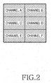
- FIG. 2 illustrates an example of a channel mosaic service in accordance with the first exemplary embodiment of the present invention.
- a channel mosaic media composition scheme is a technology for controlling a scene structure required to display all channel contents which are currently provided on one media by dividing one media of the terminal in the tile mode and displaying contents of decoded channels (such as, Channel A ⁇ Channel F) on division regions.
- decoded channels such as, Channel A ⁇ Channel F
- FIG. 3 illustrates an example of a scene structure of a channel circulation scheme in accordance with the second exemplary embodiment of the present invention.
- an ES of each channel (of Channel A ⁇ Channel F) multiplexed and combined in one group is displayed on the screen of the mobile terminal during an allocated display time indicated by the slotTime field 131 and then is switched to an ES of the next channel.
- a scene structure can be controlled by using the transition effects as shown in Table 3.
- Table 3 shows the channel transition effects and components in the example of the transitionEffect field 132.
- Table 3 Effect Name Description fadeIn Effect in which a media gradually appears Fadeout Effect in which a media gradually disappears crossFade Effect in which two medias overlap during a predetermined time while an existing media is changed to a new media Wipe Effect in which a new media appears on a region where an existing media disappears in a predetermined direction pageEffect Effect in which a media disappears or appears as if a book is paged Split Effect in which an existing media splits and disappears and then a new media appears Zoom Effect in which a new media appears in a small size and gradually increases while occupying the whole screen
- the fadeIn effect is the effect in which a media gradually appears
- the fadeOut effect is the effect in which a media gradually disappears
- the crossFade effect is the effect in which two medias overlap during a predetermined time while an existing media is switched to a new media.
- the wipe effect is the effect in which a new media appears in a region in which an existing media disappears in the left, right, top or down direction.
- the pageEffect is the effect in which a new or previous media is paged.
- the split effect is the effect in which an existing media splits and disappears and then a new media appears.
- the zoom effect is the effect in which a new or previous media appears or disappears in a small size or gradually increases while occupying the whole screen.
- the third exemplary embodiment of the present invention is a method for controlling a scene structure in a hybrid or combination scheme that can compensate for a disadvantage of the channel mosaic scene composition mode and benefit from an advantage of the channel circulation scene structure.
- FIG. 4 illustrates an example of a scene structure of the combination scheme in accordance with the third exemplary embodiment of the present invention.
- an entire screen to be displayed is divided into a main media region 41 and a sub-media region 43 using a clip path technology through a display means of the mobile terminal.
- contents of multiple channels 411 are allocated to the main media region 41 which is larger than the sub-media region 43, for a channel circulation scene structure service in the channel circulation scheme as described with reference to the second exemplary embodiment of the present invention.
- the sub-media region 43 displays decoded channel content on an associated channel region (of Channel A - Channel F), such that the contents of all the channels currently being provided can be displayed on one media.
- FIG. 5 is a block diagram illustrating a structure of a receiver in the mobile broadcast system in accordance with an exemplary embodiment of the present invention.
- a demultiplexer (DEMUX) 510 separates multiple logical channels transmitted in one physical channel on a channel-by-channel basis.
- the separated channels are allocated to multiple decoding buffers 530, such as, 530 1 ⁇ 530 n .
- a decoder 550 which is selectively or cyclically connected to the multiple decoding buffers 530 selects or circulates a logical channel frame stored in each decoding buffer 530.
- the decoder 550 then decodes an associated logical channel, and outputs the decoded logical channel to a composition memory (CM) 570.
- CM composition memory
- an media compositor 590 composes and displays a frame of each decoded logical channel stored in the composition memory 570 on a screen of the terminal.
- the media compositor 590 is configured to control the scene structure of the channel mosaic scheme in accordance with the first exemplary embodiment of the present invention, the scene structure of the channel circulation scheme in accordance with the second exemplary embodiment of the present invention, or the scene structure of the combination scheme in accordance with the third exemplary embodiment of the present invention.
- the media compositor 590 can selectively control the scene structure of the channel circulation scheme, the combination scheme, or the channel mosaic scheme.
- a method for controlling a scene structure of multiple channels in accordance with an exemplary embodiment of the present invention will be described with reference to FIGS. 6 to 8.
- the method which is described below is an operation of the media compositor 509 of FIG. 5.
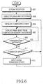
- FIG. 6 is a flowchart illustrating a method for controlling the scene structure of the channel circulation scheme in accordance with the second exemplary embodiment of the present invention.
- the demultiplexer 510 separates multiplexed logical channels on a channel-by-channel basis and allocates the separated logical channels to the decoding buffers 530 in step 603.
- the decoder 550 circulates the logical channels output to the decoding buffers 530, decodes the associated logical channels to ESs, and outputs the decoded ESs to the composition memory 570.
- the media compositor 590 of FIG. 5 initializes an internal composition timer (not illustrated) in step 605.
- frames of the channel-by-channel ESs are read from the composition memory 570 according to a designated sequence number or randomly and then displayed on the screen of the mobile terminal. The frames are read and displayed by the media compositor 590.
- the media compositor 590 determines whether a display time of one logical channel counted through the internal composition timer has elapsed by a designated slot time (slotTime(n)) of each ES. If the slot time (slotTime(n)) has not elapsed, the media compositor 590 proceeds to step 607 to continuously display a scene of an associated logical channel. If the composition timer has reached the slot time (slotTime(n)), the media compositor 590 proceeds to step 611. In step 611, the media compositor 590 determines whether to apply scene transition effect. If the scene transition effect is set, the media compositor 590 applies the scene transition effect in step 613 and then proceeds to step 605 to repeat initialization of the timer and to display an ES of the next logical channel on the screen.
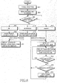
- FIG. 7 is a flowchart illustrating a method for controlling the scene structure of the combination scheme in accordance with the third exemplary embodiment of the present invention.
- the demultiplexer 510 separates multiplexed logical channels on a channel-by-channel basis and allocates the separated logical channels to the decoding buffers 530 in step 703.
- the decoder 550 circulates the logical channels output to the decoding buffers 530, decodes the associated logical channels to ESs, and outputs the decoded ESs to the composition memory 570.
- the media compositor 590 divides the entire media to be displayed on the terminal into the main media region 41 for the channel circulation scene structure and the sub-media region 43 to which channel-by-channel regions are allocated.
- the media compositor 590 divides the entire screen by using a clip path as illustrated in the example of FIG. 4.
- step 707 the media compositor 590 reads frames of ESs mapped to channel-by-channel regions from the composition memory 570 and allocates and displays the read frames on the associated channel-by-channel regions. Further, the media compositor 590 in which a media division operation has been performed in step 705 initializes the internal composition timer so that the channel circulation scene structure may be displayed on the main media region 41 in step 709. In step 711, the media compositor 590 reads frames of the channel-by-channel ESs from the composition memory 570 according to a designated sequence number or randomly and then displays the frames on the main media region 41. In FIG. 7, steps 707 and 711 are divided. However, steps 707 and 711 can be simultaneously performed.
- the media compositor 590 determines whether a display time of one logical channel counted through the internal composition timer has elapsed by a designated slot time (slotTime(n)). If the slot time (slotTime(n)) has not elapsed, the media compositor 590 proceeds to step 711 to continuously display a scene of an associated logical channel. If the composition timer has reached the slot time (slotTime(n)), the media compositor 590 proceeds to step 715. In step 715, the media compositor 590 determines whether to apply scene transition effect. If the scene transition effect is set, the media compositor 590 applies the scene transition effect in step 717 and then proceeds to step 709 to repeat a task for initializing the timer and to display an ES of the next logical channel on the screen.
- FIG. 8 is a flowchart illustrating an operation for selectively implementing the scene structure of the channel mosaic scheme, the channel circulation scheme or the combination scheme in the media compositor 590 of FIG. 5 in accordance with an exemplary embodiment of the present invention.
- the demultiplexer 510 separates multiplexed logical channels on a channel-by-channel basis and allocates the separated logical channels to the decoding buffers 530 in step 803.
- the decoder 550 circulates the logical channels output to the decoding buffers 530, decodes the associated logical channels to ESs, and outputs the decoded ESs to the composition memory 570.
- the media compositor 590 determines display mode of the associated group ID when a physical channel with a new group ID has been received.
- the dynamic mosaic field 130 includes the playList field 133 for sequentially displaying different streams of a group on scene, the tile field 134 for displaying all streams of the group on one scene, and the combination field 135 in which two schemes are combined. According to the three fields, the display modes are possible.
- the media compositor 590 divides screen using clip path information and allocates regions on a logical channel-by-channel basis in step 809. In step 811, the media compositor 590 reads and displays frames of ESs mapped to the channel-by-channel regions from the composition memory 570.
- the media compositor 590 When the display mode determined in step 805 is a channel circulation scene structure indicated by the playList field 133 of FIG. 1 in step 817, the media compositor 590 initializes the timer in step 819 and then reads and displays an ES of one logical channel from the composition memory 570 in step 821. In step 823, the media compositor 590 determines whether a display time of one logical channel counted through the internal composition timer has elapsed by a designated slot time (slotTime(n)). If the slot time (slotTime(n)) has not elapsed, the media compositor 590 proceeds to step 821 to continuously display a scene of an associated logical channel.
- slotTime(n) the slot time
- the media compositor 590 proceeds to step 825.
- the media compositor 590 determines whether to apply scene transition effect. If the scene transition effect is set, the media compositor 590 applies the scene transition effect in step 827 and then proceeds to step 819 to repeat a task for initializing the timer and to display an ES of the next logical channel on the screen.
- the media compositor 590 divides the entire screen into the main media region 41 and the sub-media region 43 by using clip path information in step 815.
- a display operation of the sub-media region 43 allocates regions on a logical channel-by-channel basis in step 811.
- the media compositor 590 initializes the timer to construct a channel circulation scene structure to be displayed on the main media region in step 819 and reads an ES of each channel from the composition memory 590 to display the read ES on the screen in step 821.
- the media compositor 590 repeats an operation for displaying an ES of the next logical channel after verifying and applying the designated transition effect.
- An exemplary embodiment of the present invention may define a channel circulation scene structure and a combination scene structure and may define a new node and method in order to address a problem in identifying logical channel stream content in service when a media of the mobile terminal is divided into tiles and the channels are displayed for the channel mosaic service.
- FIGS. 9 and 10 A process in which a user terminal composes a multi-channel media without use of an additional mosaic channel in accordance with another exemplary embodiment of the present invention will be described with reference to FIGS. 9 and 10.
- the terminal's decoder transfers decoded stream node information to the media compositor without transmitting an additional mosaic channel, such that a mosaic channel is constructed to dynamically compose a media of the multiple logical channels.
- the service provider provides the user terminal with the stream source node information of FIG. 9 including information about multiplexed logical channels and composition information for composing the multi-channel media.
- FIG. 9 is another example of a structure of a stream source for a scene structure of multiple channels in the mobile broadcast system in accordance with an exemplary embodiment of the present invention.
- a stream source node 900 of FIG. 9 is an extension of the stream source node of the conventional LASeR technology.
- Information transmitted through the stream source node 900 includes a stream source ID field 910, a source field 920, a source index field 930, width/height field 940 and a mode field.
- the source field 920 indicates a list of IDs of media sources, such as, ESs (of logical channels), to be referred to by the stream source.
- the source index field 930 indicates an index of a media source used to construct the current scene structure to be displayed through the terminal.
- the width/height field 940 indicates a buffer size and a mode field 950 indicates the display mode as illustrated in FIG. 9.
- media source IIDs included in the source field 920 in FIG. 9 are selected from channels viewed by users at a high hit rate.
- the mode field 950 includes a replace field 951 for immediately switching a media when the source index is changed and a use Old field 952 for continuously composing an ES of a previous source index on the media until media composition of a new source index is prepared.
- the mode field 950 also includes a keepOld field 953 for decoding an ES of the previous source index and composing the decoded ES on the media while continuously receiving the ES of the previous source index until the media composition of the new source index is prepared in a concept similar to that of the useOld mode, and a playList field 954 for sequentially displaying different streams of a group on a media.
- a slotTime field 954a for indicating a display time allocated to each ES and a transitionEffect field 954b to be used when one ES is switched to another ES are additionally defined in order to compose media in a mosaic or round-robin scheme using the playList mode.
- Table 4 shows fields included in the stream source node 900 of FIG. 9.
- Table 4 StreamSource ID ID Field source Field for indicating a list of media source IDs to be referred to by a stream source sourceIndex Field for indicating an index of a source stream used for the current scene buffe rSize (width, height) Field for indicating a buffer size mode replace replace field for immediately switching a media when a source index is changed useOld useOld field for continuously composing an ES of a previous source index on the media until media composition of a new source index is prepared keepOld keepOld field for decoding an ES of a previous source index and composing the decoded ES on a media while continuously receiving the previous source index until media composition of a new source index is prepared in a concept similar to that of the use Old mode playList slotTime Media display time allocated to each source TransitionEf fect Transition effect when one elementary source is changed to another elementary source
- FIG. 3 An example of a scene structure of a channel circulation scheme is illustrated in FIG. 3 when a multi-channel scene structure is controlled using the stream source node 900 of FIG. 9.
- the transition effects and components at the time of channel switching are illustrated in Table 3. Therefore, a detailed description is omitted.
- display structures such as a channel mosaic scene structure is provided to display the multiplexed channels in service using the stream source node 900 on one media. Also provided, is a channel circulation scene structure for cyclically displaying the multiplexed channels on one media in designated order, and a combination scene structure for displaying the multiplexed channels in a state in which the channel mosaic scene structure and the channel circulation scene structure are combined.
- the above-described display structures can be applied to other exemplary embodiments of the present invention.
- the user terminal to which this exemplary embodiment of the present invention is applied may employ the structure of FIG. 5.
- the decoder 550 of FIG. 5 decodes information of the stream source node 900 received from the service provider and outputs the decoded information to the media compositor 590.
- the media compositor 590 dynamically composes the multi-channel media using the information of the stream source node 900 in a scheme selected from the channel mosaic scene structure and the channel circulation scene structure.
- the demultiplexer 510 separates multiple logical channels transmitted in one physical channel and allocates the separated channels to the decoding buffers 530.
- the decoder 550 decodes the information of the stream source node 900 received from the service provider to output the decoded information to the media compositor 590. Further, the decoder 550 circulates logical channel data stored in the decoding buffers 531 1 ⁇ 531 n , decodes an associated logical channel, and outputs the decoded logical channel to the composition memory 570.
- the media compositor 590 composes and displays a frame of each decoded logical channel stored in the composition memory 570 on the media by referring to the information of the stream source node 900.
- FIG. 10 is a flowchart illustrating a method for controlling the scene structure of the multiple channels by using the stream source of FIG. 9.
- the demultiplexer 510 separates multiplexed logical channels on a channel-by-channel basis and allocates the separated logical channels to the decoding buffers 530 in step 1003 when the mobile terminal receives LASeR data streams of multiple channels from the service provider in step 1001.
- the decoder 550 decodes channel-by-channel streams output to the decoding buffers 530 and outputs decoded ESs of the logical channels to the composition memory 570.
- the media compositor 590 determines the display mode of an associated group ID when a physical channel with a new group ID has been received.
- the media compositor 590 allocates channel-by-channel regions using the information of the stream source node 900 received from the decoder 550 in step 1009. In step 1011, the media compositor 590 reads and displays frames of ESs mapped to channel-by-channel regions from the composition memory 570.
- the media compositor 590 When a determination is made that the display mode is the channel circulation scene structure in step 1013, the media compositor 590 initializes the timer and reads and displays an associated ES from the composition memory 570. When a designated slot time for displaying one logical channel has elapsed, the media compositor 590 displays an ES of the next logical channel after verifying and applying the designated transition effect in steps 1015 to 1023. Because steps 1015 to 1023 are the same as steps 819 to 827 of FIG. 8, a detailed description is omitted.
- the conventional LASeR technology provides a multi-channel scene structure service on an additional mosaic channel.
- the terminal expresses multiple ESs from the service provider in one group without using an additional mosaic channel.
- Various multi-channel medias can be dynamically composed using information of the stream source node 900 including media structure information.
- a terminal of a mobile broadcast system can receive logically multiplexed channels and control a media structure using stream source information received from a service provider.
- an exemplary embodiment of the present invention may efficiently employ channel resources by composing a logically multiplexed channel scene without use of an additional mosaic channel.
- An exemplary embodiment of the present invention may also prevent the degradation of media quality when channel-by-channel medias are multiplexed and encoded into one mosaic channel in order to compose a multiplexed channel media in the mobile broadcast system.
- an exemplary embodiment of the present invention may control a media structure of a channel circulation or combination scene structure in the mobile broadcast system, such that a user may easily identify service content on a terminal screen with a limited size and all channels are circulated and viewed in the channel circulation scene structure without user input.
- An exemplary embodiment of the present invention may be integrated with a channel mosaic service proposed in the conventional LASeR technology.
- an exemplary embodiment of the present invention may be compatible with the conventional LASeR technology and may exploit features of the conventional LASeR in an efficient media structure using a synchronization packet structure and scalable vector graphics (SVG).
- SVG scalable vector graphics
Landscapes
- Engineering & Computer Science (AREA)
- Multimedia (AREA)
- Signal Processing (AREA)
- Life Sciences & Earth Sciences (AREA)
- Chemical & Material Sciences (AREA)
- Marketing (AREA)
- Computer Security & Cryptography (AREA)
- Zoology (AREA)
- Business, Economics & Management (AREA)
- Polymers & Plastics (AREA)
- General Engineering & Computer Science (AREA)
- Food Science & Technology (AREA)
- Nutrition Science (AREA)
- Health & Medical Sciences (AREA)
- Marine Sciences & Fisheries (AREA)
- Wood Science & Technology (AREA)
- Two-Way Televisions, Distribution Of Moving Picture Or The Like (AREA)
- Circuits Of Receivers In General (AREA)
- Mobile Radio Communication Systems (AREA)
- Television Systems (AREA)
Abstract
Description
- The present invention generally relates to a display technology of a mobile terminal in a mobile broadcast system. More particularly, the present invention relates to a method, apparatus and system for controlling a scene structure of a mobile terminal for receiving and displaying data streams in a mobile broadcast system.
- Lightweight Application Scene Representation (LASeR) is the format of multimedia content for a rich multimedia service in terminals such as mobile phones which may suffer from communication resource shortages. The LASeR is analogous to the technology of the Moving Picture Experts Group-4 Binary Format for Scene (MPEG-4 BIFS). The BIFS is the scene description standard for all multimedia contents and the LASeR is the scene description standard for multimedia terminals such as mobile phones small display sizes and a reduced network bandwidth.
- The BIFS is used for an object-based system. In the object-based system, multimedia is a set of objects. Temporal and spatial information of each of the media must be indicated. For example, when the weather forecast is broadcast, four objects such as a weather caster, a weather chart displayed behind the weather caster, speech of the weather caster, and background music can be considered. When the multiple objects are present independently, an appearing time, disappearing time and position of each object should be defined to describe one scene. This definition is the BIFS. Because related information is stored in a binary file according to the BIFS, the storage capacity is reduced.
- However, the BIFS has a large amount of data of about 200 pages as described in the MPEG-4 system standard document (International Organization for Standardization/International Electro-technical Commission (ISO/IEC) 14496-1). It is difficult to use the BIFS in communication environments suffering from a shortage of available resources, such as in mobile terminals. An alternative plan is the LASeR. The LASeR is the technology developed for free representations of various multimedia and interactions with users in mobile terminals with limited memory and power by performing multiplexing and synchronization processes for different elementary streams (ESs) such as a scene description, video, audio, media, font, and metadata, and minimizing complexity. The ESs have the above-described generic meaning. The ESs are considered to be individual logical channels configuring multiple channels to be displayed.
- The LASeR ES is constructed with an access unit (AU) including a command. The command is used to change the scene characteristic at a particular time. Simultaneous commands are grouped in one AU. The AU may be one scene media, short sound, one graphic media, or short animation. A LASeR browser displays ESs in a designated order. The hierarchy is present between the ESs. The LASeR browser displays scenes in order of: (1) packet reception, (2) packet decoding (AU-by-AU recovery of one media and one video clip, among others), (3) command execution, (4) audio/video object rendering, (5) user interaction (selection and dragging, among others), and (6) local connection or connection with an external information source.
- Alternatively, the standardization for the convergence of the LASeR and World Wide Web Consortium (W3C) is ongoing.. When the SVG standard is employed, audio, video, characters, medias and polyhedrons may be represented. In relation to the SVG, the conventional LASeR technology has been proposed only to compose a movie tile using a clip path of SVG 1.1 such that a channel mosaic service for multiple channels is provided. Using the LASeR technology in a mobile terminal creates a problem in identifying channel stream content in service when a screen media of the mobile terminal is tiled. Using the LASeR technology in a mobile terminal facilitates the display of channels because a screen size of the mobile terminal is smaller than those of terminal and personal computer (PC) systems for receiving existing broadcast services.
- For example, the currently proposed stream source technology for composing a multi-channel media displays multiple broadcast service channels on one screen by multiplexing multiple medias into one channel for the channel mosaic service and allocating an additional encoded mosaic service channel. When the mosaic channel service is applied to mobile broadcasting, significant costs are required for the network infrastructure construction. When limited channel resources are concerned, it is difficult to actually implement one video channel dedicated for the mosaic service in mobile broadcasting environment. When multiple medias are to be processed in a stream source scheme and are multiplexed and encoded into one channel, the media quality may be degraded.
- Accordingly, there is a need for an improved system and method for accurately implementing one video channel dedicated for a mosaic service when limited channel resources are considered and to reduce the degradation of media quality.
- An aspect of exemplary embodiments of the present invention is to address at least the above problems and/or disadvantages and to provide at least the advantages described below. Accordingly, an aspect of an exemplary embodiment of the present invention is to provide a method, apparatus and system for controlling a scene structure to be displayed on a mobile terminal in a mobile broadcast system for providing a broadcast service in a stream source scheme.
- It is another object of an exemplary embodiment of the present invention to provide a method, apparatus and system for controlling a scene structure to be displayed on a mobile terminal for receiving a broadcast service when multiple logical channels are multiplexed into one physical channel in a mobile broadcast system.
- It is yet another object of an exemplary embodiment of the present invention to provide a method, apparatus and system for controlling a scene structure of multiple channels that can compose and display a multiplexed channel media on a mobile terminal without transmitting an additional mosaic channel when multiple logical channels are multiplexed into one physical channel in a mobile broadcast system.
- In accordance with an aspect of an exemplary embodiment of the present invention, there is provided a method for controlling a scene structure of multiple channels to be displayed on a mobile terminal in a mobile broadcast system. A physical channel is received into which multiple logical channels are multiplexed for a broadcast service from a service provider and stream source node information for controlling the scene structure. The received physical channel is demultiplexed and decoded on a logical channel-by-logical channel basis. Logical channel-by-logical channel elementary streams are displayed on an screen in at least one display mode provided from the stream source node information.
- In accordance with another aspect of an exemplary embodiment of the present invention, there is provided an apparatus for receiving a broadcast service in a mobile terminal of a mobile broadcast system. This apparatus comprises a receiver, a demultiplexor, a buffer and an media compositor. The receiver receives a physical channel into which multiple logical channels are multiplexed for a broadcast service from a service provider and stream source node information for controlling a scene structure. The demultiplexer demultiplexes the received physical channel on a logical channel-by-logical channel basis. The buffer divides and stores logical channel-by-logical channel elementary streams. The media compositor controls an operation for displaying the logical channel-by-logical channel elementary streams on an screen in at least one display mode provided from the stream source node information.
- In accordance with yet another aspect of an exemplary embodiment of the present invention, there is provided a mobile broadcast system for providing a broadcast service to at least one mobile terminal, comprising a service provider and a mobile terminal. The service provider receives a physical channel into which multiple logical channels are multiplexed for the broadcast service and stream source node information for controlling a scene structure. The mobile terminal receives the physical channel and the stream source node information through a predetermined communication network and displaying a multi-channel media. The mobile terminal comprises a demultiplexer, a buffer and an media compositor. The demultiplexer demultiplexes the received physical channel on a logical channel-by-logical channel basis. The buffer divides and stores logical channel-by-logical channel elementary streams. The media compositor controls an operation for displaying the logical channel-by-logical channel elementary streams on the screen in at least one display mode provided from the stream source node information.
- The above and other exemplary objects, features and advantages of certain exemplary embodiments of the present invention will be more apparent from the following description taken in conjunction with the accompanying drawings, in which:
- FIG. 1 illustrates an example of a structure of a stream source for a scene structure of multiple channels in a mobile broadcast system in accordance with an exemplary embodiment of the present invention;
- FIG. 2 illustrates an example of a channel mosaic service in accordance with a first exemplary embodiment of the present invention;
- FIG. 3 illustrates an example of a scene structure of a channel circulation scheme in accordance with a second exemplary embodiment of the present invention;
- FIG. 4 illustrates an example of a scene structure of a combination scheme in accordance with a third exemplary embodiment of the present invention;
- FIG. 5 is a block diagram illustrating a structure of a receiver in the mobile broadcast system in accordance with an exemplary embodiment of the present invention;
- FIG. 6 is a flowchart illustrating a method for controlling the scene structure of the channel circulation scheme in accordance with the second exemplary embodiment of the present invention;
- FIG. 7 is a flowchart illustrating a method for controlling the scene structure of the combination scheme in accordance with the third exemplary embodiment of the present invention;
- FIG. 8 is a flowchart illustrating an operation for selectively implementing the scene structure of the channel mosaic scheme, the channel circulation scheme or the combination scheme in accordance with an exemplary embodiment of the present invention;
- FIG. 9 illustrates another example of a structure of a stream source for a scene structure of multiple channels in the mobile broadcast system in accordance with an exemplary embodiment of the present invention; and
- FIG. 10 is a flowchart illustrating a method for controlling the scene structure of the multiple channels using the stream source of FIG. 9.
- Throughout the drawings, the same drawing reference numerals will be understood to refer to the same elements, features and structures.
- The matters defined in the description such as a detailed construction and elements are provided to assist in a comprehensive understanding of the embodiments of the invention. Accordingly, those of ordinary skill in the art will recognize that various changes and modifications of the embodiments described herein can be made without departing from the scope and spirit of the invention. Also, descriptions of well-known functions and constructions are omitted for clarity and conciseness.
- According to a basic concept, an exemplary embodiment of the present invention proposes a stream source node structure in which a terminal at a receiving side directly composes and displays a multiplexed media channel in a state in which any additional channel for composing a media is not transmitted when multiple logical channels are multiplexed into one physical channel in a mobile broadcast system. In a method for composing a channel mosaic channel using the stream source node in accordance with a first exemplary embodiment of the present invention, all multiple channels which are currently provided may be displayed on one screen. According to an exemplary implementation, the whole screen is divided in the form of tiles and each division region displays one channel. A second exemplary embodiment of the present invention proposes a method for controlling a scene structure in a channel circulation scheme for displaying channels currently being provided in a time sequence. When the channel circulation scheme is employed to alternately display logically multiplexed channels on one media in designated order, only one channel is displayed on a screen of the mobile terminal with a limited size. This facilitates a user's ability to easily identify service content. A third exemplary embodiment of the present invention provides a combination of the channel mosaic scene structure and the channel circulation scene structure, such that the screen with the limited size in the mobile terminal may be efficiently employed. The third exemplary embodiment of the present invention may employ the benefit of the channel circulation scheme in which the user can sequentially retrieve all channels currently being provided without additionally inputting a key. The exemplary embodiments of the present invention for a multi-channel scene structure service will be described in detail.
- FIG. 1 illustrates an example of a structure of a stream source for a scene structure of multiple channels in a mobile broadcast system in accordance with an exemplary embodiment of the present invention. A type of a
stream source node 100 as illustrated in FIG. 1 is based on a Lightweight Application Scene Representation (LASeR) technology for the multi-channel scene structure. - Information to be transmitted from the
stream source node 100 includes a unique identifier (ID) field of a stream source, and a staticmosaic field 120 for indicating static mosaic composition mode and a dynamicmosaic field 130 for indicating dynamic mosaic composition mode for a media representation. Further, the staticmosaic field 120 includes asource field 121 for indicating IDs of media sources to be referred to by the stream source, asource index field 122 for indicating an index of a source used to compose a current scene, and awidth field 123 and aheight field 124 for indicating a buffer size. - The static
mosaic field 120 further includes a replacefield 125, auseOld field 126 and akeepOld field 127. The replacefield 125 immediately switches a media when thesource index 122 is changed in display mode. TheuseOld field 126 continuously composes a previous source index on a media until media composition of a new source index is prepared. ThekeepOld field 127 decodes a previous source index and composes the decoded source index on the media while the previous source index is continuously received until the media composition of the new source index is prepared in a manner similar to that of the useOld mode. Alternatively, the dynamicmosaic field 130 includes aplayList field 133, atile field 134 and acombination field 135. Theplaylist field 133 sequentially displays different streams of a group on the media and thetile field 134 displays all streams of the group on one media. Two schemes are combined in thecombination field 135. Further, the dynamicmosaic field 130 can additionally include aslotTime field 131 for indicating a display time allocated to each source stream (such as, each elementary stream (ES)) for composing one media in the tile or combination scheme and atransitionEffect field 132 to be used when one source stream is switched to another source stream. - Table 1 shows the fields included in the
stream source node 100.Table 1 Field Description ID ID of a stream source staticMosaic Static mosaic composition mode source Field for indicating array of grouped stream IDs sourceIndex Field for indicating an index of a source stream selected from the current media width Field for indicating a buffer size height Field for indicating a buffer size mode Replace Mode for immediately switching a media when a source index is changed useOld Mode for continuously composing a previous source index until media composition of a new source index is prepared keepOld Mode for decoding a previous source index and composing the decoded source index on a media while continuously receiving the previous source index until media composition of a new source index is prepared dynamicMosaic Dynamic mosaic composition mode slotTime Media display time allocated to each source stream transitionEffect Transition effect when each source stream is changed mode playList (FIG. 3) Sequential media composition mode tile (FIG. 2) Mode for displaying all source streams on one media combinat ion (FIG. 4) Combination mode in which sequential mode and tile mode are combined - Table 2a and Table 2b illustrate a description in which the
stream source node 100 is expressed in extensible markup language (XML). For convenience, one description is divided into Table 2a and Table 2b.


- The exemplary embodiments of the present invention using the
stream source 100 of FIG. 1 will be described in detail. - FIG. 2 illustrates an example of a channel mosaic service in accordance with the first exemplary embodiment of the present invention.
- Referring to FIG. 2, a channel mosaic media composition scheme is a technology for controlling a scene structure required to display all channel contents which are currently provided on one media by dividing one media of the terminal in the tile mode and displaying contents of decoded channels (such as, Channel A ~ Channel F) on division regions. When the
tile mode 134 is selected in the dynamicmosaic field 130 for indicating the dynamic mosaic composition mode of thestream source node 100 of FIG. 1, a media is composed in a channel mosaic scheme as illustrated in FIG. 2. - FIG. 3 illustrates an example of a scene structure of a channel circulation scheme in accordance with the second exemplary embodiment of the present invention.
- Referring to FIG. 3, an ES of each channel (of Channel A ~ Channel F) multiplexed and combined in one group is displayed on the screen of the mobile terminal during an allocated display time indicated by the
slotTime field 131 and then is switched to an ES of the next channel. When the channel is switched, a scene structure can be controlled by using the transition effects as shown in Table 3. - Table 3 shows the channel transition effects and components in the example of the
transitionEffect field 132.Table 3 Effect Name Description fadeIn Effect in which a media gradually appears Fadeout Effect in which a media gradually disappears crossFade Effect in which two medias overlap during a predetermined time while an existing media is changed to a new media Wipe Effect in which a new media appears on a region where an existing media disappears in a predetermined direction pageEffect Effect in which a media disappears or appears as if a book is paged Split Effect in which an existing media splits and disappears and then a new media appears Zoom Effect in which a new media appears in a small size and gradually increases while occupying the whole screen - In Table 3, the fadeIn effect is the effect in which a media gradually appears, the fadeOut effect is the effect in which a media gradually disappears, and the crossFade effect is the effect in which two medias overlap during a predetermined time while an existing media is switched to a new media. The wipe effect is the effect in which a new media appears in a region in which an existing media disappears in the left, right, top or down direction. The pageEffect is the effect in which a new or previous media is paged. The split effect is the effect in which an existing media splits and disappears and then a new media appears. The zoom effect is the effect in which a new or previous media appears or disappears in a small size or gradually increases while occupying the whole screen.
- The third exemplary embodiment of the present invention is a method for controlling a scene structure in a hybrid or combination scheme that can compensate for a disadvantage of the channel mosaic scene composition mode and benefit from an advantage of the channel circulation scene structure.
- FIG. 4 illustrates an example of a scene structure of the combination scheme in accordance with the third exemplary embodiment of the present invention.
- Referring to FIG. 4, an entire screen to be displayed is divided into a
main media region 41 and asub-media region 43 using a clip path technology through a display means of the mobile terminal. For example, contents ofmultiple channels 411 are allocated to themain media region 41 which is larger than thesub-media region 43, for a channel circulation scene structure service in the channel circulation scheme as described with reference to the second exemplary embodiment of the present invention. According to an exemplary implementation, thesub-media region 43 displays decoded channel content on an associated channel region (of Channel A - Channel F), such that the contents of all the channels currently being provided can be displayed on one media. - FIG. 5 is a block diagram illustrating a structure of a receiver in the mobile broadcast system in accordance with an exemplary embodiment of the present invention.
- In FIG. 5, a demultiplexer (DEMUX) 510 separates multiple logical channels transmitted in one physical channel on a channel-by-channel basis. The separated channels are allocated to
multiple decoding buffers 530, such as, 5301 ~ 530n. Adecoder 550 which is selectively or cyclically connected to themultiple decoding buffers 530 selects or circulates a logical channel frame stored in eachdecoding buffer 530. Thedecoder 550 then decodes an associated logical channel, and outputs the decoded logical channel to a composition memory (CM) 570. To compose a media to be displayed, anmedia compositor 590 composes and displays a frame of each decoded logical channel stored in thecomposition memory 570 on a screen of the terminal. - In FIG. 5, the
media compositor 590 is configured to control the scene structure of the channel mosaic scheme in accordance with the first exemplary embodiment of the present invention, the scene structure of the channel circulation scheme in accordance with the second exemplary embodiment of the present invention, or the scene structure of the combination scheme in accordance with the third exemplary embodiment of the present invention. In FIG. 5, themedia compositor 590 can selectively control the scene structure of the channel circulation scheme, the combination scheme, or the channel mosaic scheme. - A method for controlling a scene structure of multiple channels in accordance with an exemplary embodiment of the present invention will be described with reference to FIGS. 6 to 8. The method which is described below is an operation of the media compositor 509 of FIG. 5.
- FIG. 6 is a flowchart illustrating a method for controlling the scene structure of the channel circulation scheme in accordance with the second exemplary embodiment of the present invention.
- When the mobile terminal receives LASeR data streams of multiple channels from a service provider in
step 601, thedemultiplexer 510 separates multiplexed logical channels on a channel-by-channel basis and allocates the separated logical channels to the decoding buffers 530 instep 603. Thedecoder 550 circulates the logical channels output to the decoding buffers 530, decodes the associated logical channels to ESs, and outputs the decoded ESs to thecomposition memory 570. When the channel-by-channel decoded ESs are output to thecomposition memory 570, the media compositor 590 of FIG. 5 initializes an internal composition timer (not illustrated) instep 605. In step 607, frames of the channel-by-channel ESs are read from thecomposition memory 570 according to a designated sequence number or randomly and then displayed on the screen of the mobile terminal. The frames are read and displayed by themedia compositor 590. - In
step 609, themedia compositor 590 determines whether a display time of one logical channel counted through the internal composition timer has elapsed by a designated slot time (slotTime(n)) of each ES. If the slot time (slotTime(n)) has not elapsed, themedia compositor 590 proceeds to step 607 to continuously display a scene of an associated logical channel. If the composition timer has reached the slot time (slotTime(n)), themedia compositor 590 proceeds to step 611. Instep 611, themedia compositor 590 determines whether to apply scene transition effect. If the scene transition effect is set, themedia compositor 590 applies the scene transition effect instep 613 and then proceeds to step 605 to repeat initialization of the timer and to display an ES of the next logical channel on the screen. - FIG. 7 is a flowchart illustrating a method for controlling the scene structure of the combination scheme in accordance with the third exemplary embodiment of the present invention.
- When the mobile terminal receives LASeR data streams of multiple channels from the service provider in
step 701, thedemultiplexer 510 separates multiplexed logical channels on a channel-by-channel basis and allocates the separated logical channels to the decoding buffers 530 instep 703. Thedecoder 550 circulates the logical channels output to the decoding buffers 530, decodes the associated logical channels to ESs, and outputs the decoded ESs to thecomposition memory 570. Instep 705, themedia compositor 590 divides the entire media to be displayed on the terminal into themain media region 41 for the channel circulation scene structure and thesub-media region 43 to which channel-by-channel regions are allocated. The media compositor 590 divides the entire screen by using a clip path as illustrated in the example of FIG. 4. - In
step 707, themedia compositor 590 reads frames of ESs mapped to channel-by-channel regions from thecomposition memory 570 and allocates and displays the read frames on the associated channel-by-channel regions. Further, themedia compositor 590 in which a media division operation has been performed instep 705 initializes the internal composition timer so that the channel circulation scene structure may be displayed on themain media region 41 instep 709. Instep 711, themedia compositor 590 reads frames of the channel-by-channel ESs from thecomposition memory 570 according to a designated sequence number or randomly and then displays the frames on themain media region 41. In FIG. 7,steps - In
step 713, themedia compositor 590 determines whether a display time of one logical channel counted through the internal composition timer has elapsed by a designated slot time (slotTime(n)). If the slot time (slotTime(n)) has not elapsed, themedia compositor 590 proceeds to step 711 to continuously display a scene of an associated logical channel. If the composition timer has reached the slot time (slotTime(n)), themedia compositor 590 proceeds to step 715. Instep 715, themedia compositor 590 determines whether to apply scene transition effect. If the scene transition effect is set, themedia compositor 590 applies the scene transition effect instep 717 and then proceeds to step 709 to repeat a task for initializing the timer and to display an ES of the next logical channel on the screen. - FIG. 8 is a flowchart illustrating an operation for selectively implementing the scene structure of the channel mosaic scheme, the channel circulation scheme or the combination scheme in the media compositor 590 of FIG. 5 in accordance with an exemplary embodiment of the present invention.
- In FIG. 8, when the mobile terminal receives LASeR data streams of multiple channels from the service provider in
step 801, thedemultiplexer 510 separates multiplexed logical channels on a channel-by-channel basis and allocates the separated logical channels to the decoding buffers 530 instep 803. Thedecoder 550 circulates the logical channels output to the decoding buffers 530, decodes the associated logical channels to ESs, and outputs the decoded ESs to thecomposition memory 570. Instep 805, themedia compositor 590 determines display mode of the associated group ID when a physical channel with a new group ID has been received. - Similar to the
stream source node 100 of FIG. 1, the dynamicmosaic field 130 includes theplayList field 133 for sequentially displaying different streams of a group on scene, thetile field 134 for displaying all streams of the group on one scene, and thecombination field 135 in which two schemes are combined. According to the three fields, the display modes are possible. - When the display mode determined in
step 805 is a channel mosaic scene structure indicated by thetile field 134 of FIG. 1 instep 807, themedia compositor 590 divides screen using clip path information and allocates regions on a logical channel-by-channel basis instep 809. In step 811, themedia compositor 590 reads and displays frames of ESs mapped to the channel-by-channel regions from thecomposition memory 570. - When the display mode determined in
step 805 is a channel circulation scene structure indicated by theplayList field 133 of FIG. 1 instep 817, themedia compositor 590 initializes the timer instep 819 and then reads and displays an ES of one logical channel from thecomposition memory 570 in step 821. Instep 823, themedia compositor 590 determines whether a display time of one logical channel counted through the internal composition timer has elapsed by a designated slot time (slotTime(n)). If the slot time (slotTime(n)) has not elapsed, themedia compositor 590 proceeds to step 821 to continuously display a scene of an associated logical channel. If the composition timer has reached the slot time (slotTime(n)), themedia compositor 590 proceeds to step 825. Instep 825, themedia compositor 590 determines whether to apply scene transition effect. If the scene transition effect is set, themedia compositor 590 applies the scene transition effect instep 827 and then proceeds to step 819 to repeat a task for initializing the timer and to display an ES of the next logical channel on the screen. - When the display mode which is determined in
step 805 is a combination scene structure indicated by thecombination field 135 of FIG. 1 instep 813, themedia compositor 590 divides the entire screen into themain media region 41 and thesub-media region 43 by using clip path information instep 815. A display operation of thesub-media region 43 allocates regions on a logical channel-by-channel basis in step 811. In the display operation of themain media region 41, themedia compositor 590 initializes the timer to construct a channel circulation scene structure to be displayed on the main media region instep 819 and reads an ES of each channel from thecomposition memory 590 to display the read ES on the screen in step 821. When a display time of one channel has elapsed by a designated slot time, themedia compositor 590 repeats an operation for displaying an ES of the next logical channel after verifying and applying the designated transition effect. - An exemplary embodiment of the present invention may define a channel circulation scene structure and a combination scene structure and may define a new node and method in order to address a problem in identifying logical channel stream content in service when a media of the mobile terminal is divided into tiles and the channels are displayed for the channel mosaic service.
- A process in which a user terminal composes a multi-channel media without use of an additional mosaic channel in accordance with another exemplary embodiment of the present invention will be described with reference to FIGS. 9 and 10.
- When multiple logical channels are multiplexed into one physical channel in this exemplary embodiment of the present invention, the terminal's decoder transfers decoded stream node information to the media compositor without transmitting an additional mosaic channel, such that a mosaic channel is constructed to dynamically compose a media of the multiple logical channels. The service provider provides the user terminal with the stream source node information of FIG. 9 including information about multiplexed logical channels and composition information for composing the multi-channel media.
- FIG. 9 is another example of a structure of a stream source for a scene structure of multiple channels in the mobile broadcast system in accordance with an exemplary embodiment of the present invention.
- A
stream source node 900 of FIG. 9 is an extension of the stream source node of the conventional LASeR technology. Information transmitted through thestream source node 900 includes a streamsource ID field 910, asource field 920, asource index field 930, width/height field 940 and a mode field. Thesource field 920 indicates a list of IDs of media sources, such as, ESs (of logical channels), to be referred to by the stream source. Thesource index field 930 indicates an index of a media source used to construct the current scene structure to be displayed through the terminal. The width/height field 940 indicates a buffer size and amode field 950 indicates the display mode as illustrated in FIG. 9. - According to an exemplary implementation, media source IIDs included in the
source field 920 in FIG. 9 are selected from channels viewed by users at a high hit rate. Themode field 950 includes a replacefield 951 for immediately switching a media when the source index is changed and ause Old field 952 for continuously composing an ES of a previous source index on the media until media composition of a new source index is prepared. Themode field 950 also includes akeepOld field 953 for decoding an ES of the previous source index and composing the decoded ES on the media while continuously receiving the ES of the previous source index until the media composition of the new source index is prepared in a concept similar to that of the useOld mode, and aplayList field 954 for sequentially displaying different streams of a group on a media. In an exemplary embodiment of the present invention, aslotTime field 954a for indicating a display time allocated to each ES and atransitionEffect field 954b to be used when one ES is switched to another ES are additionally defined in order to compose media in a mosaic or round-robin scheme using the playList mode. - Table 4 shows fields included in the
stream source node 900 of FIG. 9.Table 4 StreamSource ID ID Field source Field for indicating a list of media source IDs to be referred to by a stream source sourceIndex Field for indicating an index of a source stream used for the current scene buffe rSize (width, height) Field for indicating a buffer size mode replace replace field for immediately switching a media when a source index is changed useOld useOld field for continuously composing an ES of a previous source index on the media until media composition of a new source index is prepared keepOld keepOld field for decoding an ES of a previous source index and composing the decoded ES on a media while continuously receiving the previous source index until media composition of a new source index is prepared in a concept similar to that of the use Old mode playList slotTime Media display time allocated to each source TransitionEf fect Transition effect when one elementary source is changed to another elementary source - An example of a scene structure of a channel circulation scheme is illustrated in FIG. 3 when a multi-channel scene structure is controlled using the
stream source node 900 of FIG. 9. The transition effects and components at the time of channel switching are illustrated in Table 3. Therefore, a detailed description is omitted. - In terms of logically multiplexed channels, display structures such as a channel mosaic scene structure is provided to display the multiplexed channels in service using the
stream source node 900 on one media. Also provided, is a channel circulation scene structure for cyclically displaying the multiplexed channels on one media in designated order, and a combination scene structure for displaying the multiplexed channels in a state in which the channel mosaic scene structure and the channel circulation scene structure are combined. The above-described display structures can be applied to other exemplary embodiments of the present invention. - The user terminal to which this exemplary embodiment of the present invention is applied may employ the structure of FIG. 5. In this exemplary embodiment of the present invention, the
decoder 550 of FIG. 5 decodes information of thestream source node 900 received from the service provider and outputs the decoded information to themedia compositor 590. The media compositor 590 dynamically composes the multi-channel media using the information of thestream source node 900 in a scheme selected from the channel mosaic scene structure and the channel circulation scene structure. - In the example of the channel circulation scene structure, the
demultiplexer 510 separates multiple logical channels transmitted in one physical channel and allocates the separated channels to the decoding buffers 530. Thedecoder 550 decodes the information of thestream source node 900 received from the service provider to output the decoded information to themedia compositor 590. Further, thedecoder 550 circulates logical channel data stored in the decoding buffers 5311 ~ 531n, decodes an associated logical channel, and outputs the decoded logical channel to thecomposition memory 570. The media compositor 590 composes and displays a frame of each decoded logical channel stored in thecomposition memory 570 on the media by referring to the information of thestream source node 900. - FIG. 10 is a flowchart illustrating a method for controlling the scene structure of the multiple channels by using the stream source of FIG. 9.
- As illustrated in FIG. 10, the
demultiplexer 510 separates multiplexed logical channels on a channel-by-channel basis and allocates the separated logical channels to the decoding buffers 530 instep 1003 when the mobile terminal receives LASeR data streams of multiple channels from the service provider instep 1001. Thedecoder 550 decodes channel-by-channel streams output to the decoding buffers 530 and outputs decoded ESs of the logical channels to thecomposition memory 570. Instep 1005, themedia compositor 590 determines the display mode of an associated group ID when a physical channel with a new group ID has been received. - When the display mode is determined to be the channel mosaic scene structure in
step 1007, themedia compositor 590 allocates channel-by-channel regions using the information of thestream source node 900 received from thedecoder 550 instep 1009. Instep 1011, themedia compositor 590 reads and displays frames of ESs mapped to channel-by-channel regions from thecomposition memory 570. - When a determination is made that the display mode is the channel circulation scene structure in
step 1013, themedia compositor 590 initializes the timer and reads and displays an associated ES from thecomposition memory 570. When a designated slot time for displaying one logical channel has elapsed, themedia compositor 590 displays an ES of the next logical channel after verifying and applying the designated transition effect insteps 1015 to 1023. Becausesteps 1015 to 1023 are the same assteps 819 to 827 of FIG. 8, a detailed description is omitted. - The conventional LASeR technology provides a multi-channel scene structure service on an additional mosaic channel. However, when multiple logical channels are multiplexed into one physical channel in this exemplary embodiment of the present invention, the terminal expresses multiple ESs from the service provider in one group without using an additional mosaic channel. Various multi-channel medias can be dynamically composed using information of the
stream source node 900 including media structure information. - As is apparent from the above description, a terminal of a mobile broadcast system can receive logically multiplexed channels and control a media structure using stream source information received from a service provider.
- Moreover, an exemplary embodiment of the present invention may efficiently employ channel resources by composing a logically multiplexed channel scene without use of an additional mosaic channel.
- An exemplary embodiment of the present invention may also prevent the degradation of media quality when channel-by-channel medias are multiplexed and encoded into one mosaic channel in order to compose a multiplexed channel media in the mobile broadcast system.
- Moreover, an exemplary embodiment of the present invention may control a media structure of a channel circulation or combination scene structure in the mobile broadcast system, such that a user may easily identify service content on a terminal screen with a limited size and all channels are circulated and viewed in the channel circulation scene structure without user input.
- An exemplary embodiment of the present invention may be integrated with a channel mosaic service proposed in the conventional LASeR technology. Thus, an exemplary embodiment of the present invention may be compatible with the conventional LASeR technology and may exploit features of the conventional LASeR in an efficient media structure using a synchronization packet structure and scalable vector graphics (SVG).
- While the present invention has been shown and described with reference to certain exemplary embodiments thereof, it will be understood by those skilled in the art that various changes in form and details may be made without departing from the spirit and scope of the invention as defined by the appended claims and their equivalents.
Claims (32)
- A method for controlling a scene structure of multiple channels to be displayed on a mobile terminal in a mobile broadcast system, comprising
receiving a physical channel into which multiple logical channels are multiplexed for a broadcast service from a service provider and stream source node information for controlling the scene structure;
demultiplexing and decoding the received physical channel on a logical channel-by-logical channel basis; and
displaying logical channel-by-logical channel elementary streams on a media in at least one display mode provided from the stream source node information. - The method of claim 1, further comprising
determining the at least one display mode of a group identifier of the physical channel after receiving the physical channel. - The method of claim 1, further comprising
allocating multiple regions on the logical channel-by-logical channel basis and displaying frames of the elementary streams on the multiple regions on the logical channel-by-logical channel basis when the at least one display mode comprises a channel mosaic scene structure. - The method of claim 1, further comprising
circulating and displaying the elementary streams during a slot time on the logical channel-by-logical channel basis when the at least one display mode comprises a channel circulation scene structure. - The method of claim 4, further comprising
determining whether scene transition effect is applied when the slot time has elapsed; and
applying a scene transition effect when the elementary streams are circulated when the scene transition effect is applied. - The method of claim 1, further comprising:dividing the media into a main media region and a sub-media region using a clip path when the at least one display mode comprises a combination scene structure;circulating and displaying the elementary streams on the main media region during a slot time on the logical channel-by-logical channel basis; anddividing and displaying the elementary streams on the sub-media region on the logical channel-by-logical channel basis.
- The method of claim 1, wherein the stream source node information comprises at least one of:a static mosaic field for indicating a static mosaic composition method for a media representation; anda dynamic mosaic field for indicating a dynamic mosaic composition method for a media representation.
- The method of claim 7, wherein the static mosaic field comprises at least one of a source field for indicating a list of identifiers of logical channel-by-logical channel elementary streams to be referred to by a stream source, a source index field for indicating an index of an elementary stream used to compose a current scene, and a field for indicating a size of a buffer storing the elementary streams.
- The method of claim 8, wherein the static mosaic field further comprises at least one of a replace field for switching the media when a source index is changed, a useOld field for continuously composing an elementary stream of a previous source index on the media until media composition of a new source index is prepared, and a keepOld field for decoding the elementary stream of the previous source index and composing the decoded elementary stream on the media while continuously receiving the elementary stream of the previous source index until the media composition of the new source index is prepared.
- The method of claim 7, wherein the dynamic mosaic field comprises at least one of a playList field for sequentially displaying different streams of a group on a media in the at least one display mode, a tile field for displaying all streams of the group on one media in the at least one display mode, and a combination field in which the channel circulation scene structure and the channel mosaic scene structure are combined in the at least one display mode.
- The method of claim 1, wherein the stream source node information comprises a slotTime field for indicating a slot time in which the logical channel-by-logical channel elementary streams are displayed.
- The method of claim 1, wherein the stream source node information comprises a transitionEffect field for indicating scene transition effect when the logical channel-by-logical channel elementary streams are switched.
- An apparatus for receiving a broadcast service in a mobile terminal of a mobile broadcast system, comprising:a receiver for receiving a physical channel into which multiple logical channels are multiplexed for a broadcast service from a service provider and stream source node information for controlling a scene structure;a demultiplexer for demultiplexing the received physical channel on a logical channel-by-logical channel basis;a buffer for dividing and storing logical channel-by-logical channel elementary streams; andan media compositor for controlling an operation for displaying the logical channel-by-logical channel elementary streams on a media in at least one display mode provided from the stream source node information.
- The apparatus of claim 13, wherein the media compositor is further configured to determine the at least one display mode of a group identifier of the physical channel after receiving the physical channel.
- The apparatus of claim 13, wherein the media compositor further controls an operation for allocating multiple regions on the logical channel-by-logical channel basis, and displaying frames of the elementary streams on the multiple regions on the logical channel-by-logical channel basis when the at least one display mode comprises a channel mosaic scene structure.
- The apparatus of claim 13, wherein the media compositor further controls an operation for circulating and displaying the elementary streams during a slot time on the logical channel-by-logical channel basis when the at least one display mode comprises a channel circulation scene structure.
- The apparatus of claim 16, wherein the media compositor further controls an operation for determining whether scene transition effect is applied when the slot time has elapsed and applying a scene transition effect when the elementary streams are circulated when the scene transition effect is applied.
- The apparatus of claim 13, wherein the media compositor further controls an operation for dividing the media into a main media region and a sub-media region using a clip path when the at least one display mode comprises a combination scene structure, circulating and displaying the elementary streams on the main media region during a slot time on the logical channel-by-logical channel basis, and dividing and displaying the elementary streams on the sub-media region on the logical channel-by-logical channel basis.
- The apparatus of claim 13, wherein the stream source node information comprises at least one of:a static mosaic field for indicating a static mosaic composition method for a media representation; anda dynamic mosaic field for indicating a dynamic mosaic composition method for a media representation.
- The apparatus of claim 19, wherein the static mosaic field comprises at least one of a source field for indicating a list of identifiers of logical channel-by-logical channel elementary streams to be referred to by a stream source, a source index field for indicating an index of an elementary stream used to compose a current scene, and a field for indicating a size of a buffer storing the elementary streams.
- The apparatus of claim 20, wherein the static mosaic field further comprises at least one of a replace field for switching the media when a source index is changed, a useOld field for continuously composing an elementary stream of a previous source index on the media until media composition of a new source index is prepared, and a keepOld field for decoding the elementary stream of the previous source index and composing the decoded elementary stream on the media while continuously receiving the elementary stream of the previous source index until the media composition of the new source index is prepared.
- The apparatus of claim 19, wherein the dynamic mosaic field comprises at least one of a playList field for sequentially displaying different streams of a group on a media in the at least one display mode, a tile field for displaying all streams of the group on one media in the at least one display mode, and a combination field in which the channel circulation scene structure and the channel mosaic scene structure are combined in the at least one display mode.
- The apparatus of claim 13, wherein the stream source node information comprises a slotTime field for indicating a slot time in which the logical channel-by-logical channel elementary streams are displayed.
- The apparatus of claim 13, wherein the stream source node information comprises a transitionEffect field for indicating scene transition effect when the logical channel-by-logical channel elementary streams are switched.
- A mobile broadcast system for providing a broadcast service to at least one mobile terminal, comprising:a service provider for receiving a physical channel into which multiple logical channels are multiplexed for the broadcast service and stream source node information for controlling a scene structure; anda mobile terminal for receiving the physical channel and the stream source node information through a communication network and displaying a multi-channel media,the mobile terminal comprising:a demultiplexer for demultiplexing the received physical channel on a logical channel-by-logical channel basis;a buffer for dividing and storing logical channel-by-logical channel elementary streams; andan media compositor for controlling an operation for displaying the logical channel-by-logical channel elementary streams on the media in at least one display mode provided from the stream source node information.
- A receiver in a mobile broadcast system, comprising:a demultiplexer for separating multiple logical channels transmitted in one physical channel on a channel-by-channel basis;a plurality of decoding buffers for storing a plurality of logical channel frames;a decoder for connecting to the plurality of decoding buffers and for selecting the plurality of logical channel frames;a composition memory for storing frames of decoded logical channels; anda compositor for composing and displaying frames of each of the decoded logical channels stored in the composition memory.
- The receiver of claim 26, wherein the compositor composes and displays frames of each of the decoded logical channels stored in the composition memory on a screen of a terminal.
- An apparatus for receiving a broadcast service in a mobile terminal of a mobile broadcast system, comprising:a receiver for receiving a physical channel into which multiple logical channels are multiplexed for a broadcast service from a service provider and stream source node information for controlling a scene structure;a demultiplexer for demultiplexing the received physical channel on a logical channel-by-logical channel basis; anda buffer for dividing and storing logical channel-by-logical channel elementary streams.
- The apparatus of claim 28, further comprising an media compositor for controlling an operation for displaying the logical channel-by-logical channel elementary streams on a media in at least one display mode provided from the stream source node information.
- The apparatus of claim 29, wherein the media compositor is further configured to determine the at least one display mode of a group identifier of the physical channel after receiving the physical channel.
- The method of claim 9, wherein the static mosaic field further comprises at least one of a replace field for immediately switching the media when a source index is changed, a useOld field for continuously composing an elementary stream of a previous source index on the media until media composition of a new source index is prepared, and a keepOld field for decoding the elementary stream of the previous source index and composing the decoded elementary stream on the media while continuously receiving the elementary stream of the previous source index until the media composition of the new source index is prepared.
- The apparatus of claim 21, wherein the static mosaic field further comprises at least one of a replace field for immediately switching the media when a source index is changed, a useOld field for continuously composing an elementary stream of a previous source index on the media until media composition of a new source index is prepared, and a keepOld field for decoding the elementary stream of the previous source index and composing the decoded elementary stream on the media while continuously receiving the elementary stream of the previous source index until the media composition of the new source index is prepared.
Applications Claiming Priority (3)
| Application Number | Priority Date | Filing Date | Title |
|---|---|---|---|
| KR20050097242 | 2005-10-14 | ||
| KR20060003339 | 2006-01-11 | ||
| KR1020060028672A KR101224256B1 (en) | 2005-10-14 | 2006-03-29 | Method and apparatus for controlling scene structure of multiple channel for a mobile terminal based on light application scene representation |
Publications (2)
| Publication Number | Publication Date |
|---|---|
| EP1775955A2 true EP1775955A2 (en) | 2007-04-18 |
| EP1775955A3 EP1775955A3 (en) | 2016-08-24 |
Family
ID=38176772
Family Applications (1)
| Application Number | Title | Priority Date | Filing Date |
|---|---|---|---|
| EP06021651.2A Withdrawn EP1775955A3 (en) | 2005-10-14 | 2006-10-16 | Control of a scene structure of multiple channels to be displayed on a mobile terminal |
Country Status (7)
| Country | Link |
|---|---|
| US (1) | US8442121B2 (en) |
| EP (1) | EP1775955A3 (en) |
| JP (2) | JP4855472B2 (en) |
| KR (1) | KR101224256B1 (en) |
| CN (1) | CN101331772B (en) |
| RU (1) | RU2378766C1 (en) |
| WO (1) | WO2007043850A1 (en) |
Cited By (1)
| Publication number | Priority date | Publication date | Assignee | Title |
|---|---|---|---|---|
| US20100023530A1 (en) * | 2008-07-16 | 2010-01-28 | Samsung Electronics Co.,Ltd | Method and apparatus for providing rich media service |
Families Citing this family (15)
| Publication number | Priority date | Publication date | Assignee | Title |
|---|---|---|---|---|
| EP2089882A4 (en) * | 2006-10-19 | 2010-12-08 | Lg Electronics Inc | Encoding method and apparatus and decoding method and apparatus |
| KR100790191B1 (en) * | 2007-01-16 | 2008-01-02 | 삼성전자주식회사 | Method of providing a broadcast screen using the content of LASERR, DV-H system and terminal for the same |
| ES2675950T3 (en) * | 2007-05-30 | 2018-07-13 | Orange | Generation of a customizable TV mosaic |
| KR100827339B1 (en) * | 2007-06-15 | 2008-05-06 | (주)파인원커뮤니케이션즈 | Access to native database by laser service and its laser terminal |
| KR20080114496A (en) * | 2007-06-26 | 2008-12-31 | 삼성전자주식회사 | Method and apparatus for composing a scene using laser content |
| KR101356163B1 (en) * | 2007-07-12 | 2014-01-24 | 엘지전자 주식회사 | mobile terminal and it's channel and broadcast information indication method |
| US8595341B2 (en) * | 2008-06-30 | 2013-11-26 | At&T Intellectual Property I, L.P. | System and method for travel route planning |
| WO2013010188A1 (en) * | 2011-07-14 | 2013-01-17 | Sirius Xm Radio Inc. | Individual song libraries and personalized channels in broadcast satellite systems |
| US9600573B2 (en) | 2011-07-14 | 2017-03-21 | Sirius Xm Radio Inc. | Systems and methods for implementing dynamic banks of subchannels for broadcast or streamed content services featured favorites |
| US20130027562A1 (en) * | 2011-07-26 | 2013-01-31 | Lee Boohee | System and method for image processing using mosaic techniques |
| JP5979406B2 (en) * | 2012-02-22 | 2016-08-24 | ソニー株式会社 | Image processing apparatus, image processing method, and image processing system |
| GB201208389D0 (en) * | 2012-05-10 | 2012-06-27 | Samsung Electronics Co Ltd | Integrated circuit, communication unit, wireless communication system and methods therefor |
| US9621616B2 (en) | 2013-09-16 | 2017-04-11 | Sony Corporation | Method of smooth transition between advertisement stream and main stream |
| JP6708407B2 (en) * | 2015-12-25 | 2020-06-10 | キヤノン株式会社 | Image processing apparatus, image processing method and program |
| US11012721B2 (en) * | 2019-03-15 | 2021-05-18 | Tencent America LLC | Method and apparatus for envelope descriptor in moving picture experts group network based media processing |
Family Cites Families (19)
| Publication number | Priority date | Publication date | Assignee | Title |
|---|---|---|---|---|
| JPH07101930B2 (en) * | 1990-06-11 | 1995-11-01 | 日本ビクター株式会社 | Television receiver |
| US5696500A (en) | 1995-08-18 | 1997-12-09 | Motorola, Inc. | Multi-media receiver and system therefor |
| KR19980043984A (en) * | 1996-12-05 | 1998-09-05 | 배순훈 | Channel Search TV Using Multiple PI Screens and Searching Method |
| US6072808A (en) * | 1997-12-23 | 2000-06-06 | Intel Corporation | Method of providing and retrieving a data segment |
| US6204887B1 (en) * | 1998-12-11 | 2001-03-20 | Hitachi America, Ltd. | Methods and apparatus for decoding and displaying multiple images using a common processor |
| JP2001148816A (en) * | 1999-11-19 | 2001-05-29 | Matsushita Electric Ind Co Ltd | Synthetic screen broadcasting device and receiving device |
| US6539545B1 (en) * | 2000-01-28 | 2003-03-25 | Opentv Corp. | Interactive television system and method for simultaneous transmission and rendering of multiple encoded video streams |
| JP4552290B2 (en) * | 2000-08-21 | 2010-09-29 | ソニー株式会社 | Data transmission apparatus and method, data processing apparatus and method |
| EP1291017A3 (en) * | 2001-09-10 | 2003-07-02 | Warner-Lambert Company | Use of statins to inhibit formation of osteoclasts |
| JP4880843B2 (en) * | 2001-09-20 | 2012-02-22 | キヤノン株式会社 | Receiving apparatus and control method thereof |
| US7987491B2 (en) * | 2002-05-10 | 2011-07-26 | Richard Reisman | Method and apparatus for browsing using alternative linkbases |
| JP4366912B2 (en) * | 2002-09-10 | 2009-11-18 | ソニー株式会社 | Decoding device and decoding method |
| KR20040070507A (en) * | 2003-02-03 | 2004-08-11 | 엘지전자 주식회사 | Method for searching favorite channel of pip/pop in digital television |
| US7907665B2 (en) * | 2003-03-14 | 2011-03-15 | Lsi Corporation | Multi-channel video compression system |
| KR20040088732A (en) | 2003-04-10 | 2004-10-20 | 삼성전자주식회사 | Broadcasting service method via forward packet data channel in wireless telecommunication system |
| JP2004334058A (en) * | 2003-05-12 | 2004-11-25 | Hitachi Ltd | Display device and display control method |
| JP3754975B2 (en) * | 2003-11-18 | 2006-03-15 | キヤノン株式会社 | Information processing apparatus and information processing method |
| GB0402637D0 (en) * | 2004-02-06 | 2004-03-10 | Nokia Corp | Mobile telecommunications apparatus |
| KR20050090302A (en) | 2004-03-08 | 2005-09-13 | 경희대학교 산학협력단 | Video encoder/decoder, video encoding/decoding method and computer readable medium storing a program for performing the method |
-
2006
- 2006-03-29 KR KR1020060028672A patent/KR101224256B1/en not_active Expired - Fee Related
- 2006-10-16 EP EP06021651.2A patent/EP1775955A3/en not_active Withdrawn
- 2006-10-16 US US11/581,058 patent/US8442121B2/en not_active Expired - Fee Related
- 2006-10-16 RU RU2008114397/09A patent/RU2378766C1/en active
- 2006-10-16 WO PCT/KR2006/004181 patent/WO2007043850A1/en not_active Ceased
- 2006-10-16 CN CN2006800473051A patent/CN101331772B/en not_active Expired - Fee Related
- 2006-10-16 JP JP2008535469A patent/JP4855472B2/en not_active Expired - Fee Related
-
2011
- 2011-08-22 JP JP2011180233A patent/JP5289522B2/en not_active Expired - Fee Related
Non-Patent Citations (1)
| Title |
|---|
| None * |
Cited By (1)
| Publication number | Priority date | Publication date | Assignee | Title |
|---|---|---|---|---|
| US20100023530A1 (en) * | 2008-07-16 | 2010-01-28 | Samsung Electronics Co.,Ltd | Method and apparatus for providing rich media service |
Also Published As
| Publication number | Publication date |
|---|---|
| CN101331772A (en) | 2008-12-24 |
| JP4855472B2 (en) | 2012-01-18 |
| US8442121B2 (en) | 2013-05-14 |
| EP1775955A3 (en) | 2016-08-24 |
| WO2007043850A1 (en) | 2007-04-19 |
| JP5289522B2 (en) | 2013-09-11 |
| RU2378766C1 (en) | 2010-01-10 |
| JP2011244484A (en) | 2011-12-01 |
| RU2008114397A (en) | 2009-10-20 |
| KR20070041295A (en) | 2007-04-18 |
| CN101331772B (en) | 2010-09-29 |
| JP2009512331A (en) | 2009-03-19 |
| KR101224256B1 (en) | 2013-01-18 |
| US20070107018A1 (en) | 2007-05-10 |
Similar Documents
| Publication | Publication Date | Title |
|---|---|---|
| JP5289522B2 (en) | Method and apparatus for controlling multi-channel scene configuration for mobile terminal screen display in mobile broadcast system and system thereof | |
| US20210076084A1 (en) | System And Method For Seamless Switching Through Buffering | |
| US9313442B2 (en) | Method and apparatus for generating a broadcast bit stream for digital broadcasting with captions, and method and apparatus for receiving a broadcast bit stream for digital broadcasting with captions | |
| US7899088B2 (en) | Apparatus and method for receiving multiple streams in a mobile broadcast system | |
| CN101448152B (en) | Multi-channel video processing method and system, terminal and media server | |
| US6058122A (en) | Device for splitting a screen in MPEG image signals at a completely compressed domain and the method thereof | |
| JP2002521928A (en) | Method and apparatus for combining a video sequence with an interactive program guide | |
| EP0805591B1 (en) | Apparatus for transmitting television broadcasting program and apparatus for receiving television broadcasting program | |
| CN101267545A (en) | A program switching method and device | |
| JP2002051325A (en) | Digital broadcast video receiving apparatus and digital broadcast video receiving method | |
| CN102223569A (en) | Multi-path video processing method | |
| EP1130920A2 (en) | Method, apparatus and system for motion picture signal distribution | |
| CN102664900A (en) | Media business provision method and device, and media service display method and device | |
| EP3249939A1 (en) | Multi-media streaming service presentation method, relevant device and relevant system | |
| WO1997016020A1 (en) | System for dynamic real-time television channel expansion | |
| KR20050013029A (en) | Preview module to see multi-channel screen of NTSC & PAL to single display to Set-Top. | |
| JPH11346349A (en) | Program transmission method, program transmission device, program receiving device, and medium | |
| Xu | A Broadcasting Schedule Scheme for Both 2D and 3D Video on Demand | |
| KR20070042759A (en) | Method and apparatus for decoding audio signal |
Legal Events
| Date | Code | Title | Description |
|---|---|---|---|
| PUAI | Public reference made under article 153(3) epc to a published international application that has entered the european phase |
Free format text: ORIGINAL CODE: 0009012 |
|
| 17P | Request for examination filed |
Effective date: 20061016 |
|
| AK | Designated contracting states |
Kind code of ref document: A2 Designated state(s): AT BE BG CH CY CZ DE DK EE ES FI FR GB GR HU IE IS IT LI LT LU LV MC NL PL PT RO SE SI SK TR |
|
| AX | Request for extension of the european patent |
Extension state: AL BA HR MK YU |
|
| RAP1 | Party data changed (applicant data changed or rights of an application transferred) |
Owner name: SAMSUNG ELECTRONICS CO., LTD. |
|
| RAP1 | Party data changed (applicant data changed or rights of an application transferred) |
Owner name: SAMSUNG ELECTRONICS CO., LTD. Owner name: INDUSTRY-UNIVERSITY COOPERATION FOUNDATION HANYANG |
|
| PUAL | Search report despatched |
Free format text: ORIGINAL CODE: 0009013 |
|
| AK | Designated contracting states |
Kind code of ref document: A3 Designated state(s): AT BE BG CH CY CZ DE DK EE ES FI FR GB GR HU IE IS IT LI LT LU LV MC NL PL PT RO SE SI SK TR |
|
| AX | Request for extension of the european patent |
Extension state: AL BA HR MK RS |
|
| RIC1 | Information provided on ipc code assigned before grant |
Ipc: H04N 7/50 00000000ALI20160719BHEP Ipc: H04N 7/24 20060101AFI20160719BHEP |
|
| AKX | Designation fees paid |
Designated state(s): AT BE BG CH CY CZ DE DK EE ES FI FR GB GR HU IE IS IT LI LT LU LV MC NL PL PT RO SE SI SK TR |
|
| AXX | Extension fees paid |
Extension state: HR Extension state: MK Extension state: AL Extension state: RS Extension state: BA |
|
| STAA | Information on the status of an ep patent application or granted ep patent |
Free format text: STATUS: EXAMINATION IS IN PROGRESS |
|
| 17Q | First examination report despatched |
Effective date: 20170607 |
|
| GRAP | Despatch of communication of intention to grant a patent |
Free format text: ORIGINAL CODE: EPIDOSNIGR1 |
|
| STAA | Information on the status of an ep patent application or granted ep patent |
Free format text: STATUS: GRANT OF PATENT IS INTENDED |
|
| RIC1 | Information provided on ipc code assigned before grant |
Ipc: H04N 21/44 20110101ALI20201109BHEP Ipc: H04N 21/8543 20110101ALI20201109BHEP Ipc: H04N 21/414 20110101ALI20201109BHEP Ipc: H04N 21/2343 20110101ALI20201109BHEP Ipc: H04N 21/431 20110101ALI20201109BHEP Ipc: H04N 21/234 20110101AFI20201109BHEP Ipc: H04N 21/43 20110101ALI20201109BHEP Ipc: H04N 21/435 20110101ALI20201109BHEP Ipc: H04N 21/235 20110101ALI20201109BHEP |
|
| INTG | Intention to grant announced |
Effective date: 20201125 |
|
| STAA | Information on the status of an ep patent application or granted ep patent |
Free format text: STATUS: THE APPLICATION IS DEEMED TO BE WITHDRAWN |
|
| 18D | Application deemed to be withdrawn |
Effective date: 20210407 |