EP1775846A1 - Wireless communication terminal and portable wireless communication terminal - Google Patents
Wireless communication terminal and portable wireless communication terminal Download PDFInfo
- Publication number
- EP1775846A1 EP1775846A1 EP05755677A EP05755677A EP1775846A1 EP 1775846 A1 EP1775846 A1 EP 1775846A1 EP 05755677 A EP05755677 A EP 05755677A EP 05755677 A EP05755677 A EP 05755677A EP 1775846 A1 EP1775846 A1 EP 1775846A1
- Authority
- EP
- European Patent Office
- Prior art keywords
- wireless communication
- internal
- internal wireless
- external
- control portion
- Prior art date
- Legal status (The legal status is an assumption and is not a legal conclusion. Google has not performed a legal analysis and makes no representation as to the accuracy of the status listed.)
- Withdrawn
Links
Images




Classifications
-
- H—ELECTRICITY
- H04—ELECTRIC COMMUNICATION TECHNIQUE
- H04M—TELEPHONIC COMMUNICATION
- H04M1/00—Substation equipment, e.g. for use by subscribers
- H04M1/02—Constructional features of telephone sets
- H04M1/0202—Portable telephone sets, e.g. cordless phones, mobile phones or bar type handsets
- H04M1/0206—Portable telephones comprising a plurality of mechanically joined movable body parts, e.g. hinged housings
- H04M1/0208—Portable telephones comprising a plurality of mechanically joined movable body parts, e.g. hinged housings characterized by the relative motions of the body parts
- H04M1/0214—Foldable telephones, i.e. with body parts pivoting to an open position around an axis parallel to the plane they define in closed position
-
- H—ELECTRICITY
- H04—ELECTRIC COMMUNICATION TECHNIQUE
- H04M—TELEPHONIC COMMUNICATION
- H04M1/00—Substation equipment, e.g. for use by subscribers
- H04M1/02—Constructional features of telephone sets
- H04M1/0202—Portable telephone sets, e.g. cordless phones, mobile phones or bar type handsets
- H04M1/0206—Portable telephones comprising a plurality of mechanically joined movable body parts, e.g. hinged housings
- H04M1/0208—Portable telephones comprising a plurality of mechanically joined movable body parts, e.g. hinged housings characterized by the relative motions of the body parts
- H04M1/0225—Rotatable telephones, i.e. the body parts pivoting to an open position around an axis perpendicular to the plane they define in closed position
Definitions
- the present invention relates to a wireless communication terminal and a mobile type wireless communication terminal, and is particularly applicable to a clamshell type mobile telephone and the like.
- Recent mobile telephone handsets mostly employ the clamshell design because its foldable structure allows the mobile telephones to have a larger display size while their portability is not impaired and the design can prevent operation buttons from being accidentally pressed while the users carry the handsets around.
- the clamshell design has a first case member including a control portion that mainly controls the external wireless communication function of the mobile telephone and a second case member having a display part.
- the first and second case members are hinged together and can be opened and closed through the hinge.
- the number of pins in a flexible wiring board used for sending signals to the display part must be increased in order to transmit high bit rate image data or the like to the display part through a wire. Therefore, in a mobile telephone handset with a clamshell design, the flexible wiring board with an increased number of pins must be passed through the hinge in the case of carrying out the - data transmission between the first and second case members through a wire. This is not only an obstacle to reduce the size of the mobile telephone handset, but also pushes up the cost, and the reliability can be lowered.
- an internal wireless communication antenna may be provided in each of the first and second case members, so that data transmission between the first and second case members can be carried out by internal wireless communication.
- the communication suffers from interference with wireless communication outside the mobile telephone. Therefore, the environment for the internal wireless communication changes depending on the wireless communication outside the mobile telephone, and the reliability in surely transmitting data can be deteriorated.
- the power level is greatly different from the waves output by the wireless communication outside the mobile telephone, and the power level difference could be as large as 90 dB.
- a branch unit to branch a part of a transmission signal in a stage preceding the antenna is provided so that a very weak GPS signal can be received while transmission is carried out by the mobile communication.
- a branch signal from the branch unit is attenuated and phase-shifted to produce an interference compensation signal, and the interference compensation signal is superposed on the GPS signal.
- the branch unit, an attenuator, a phase shifter and a superposing unit are necessary. Therefore, there are the problems that a complicated and large-scale circuit configuration is necessary, and the cost, size, and weight are increased.
- An object of the invention is to provide a wireless communication terminal and a mobile wireless communication terminal that allow the communication environment to be changed by external wireless communication and reduce the deterioration in the quality of the internal wireless communication between first and second case members.
- a wireless communication terminal includes a first case member, a second case member coupled with the first case member, a coupling portion that couples the first and second case members so that the positional relation between the first and second case members can be changed, an external wireless communication antenna, an external wireless communication control portion that mainly controls external wireless communication carried out through the external wireless communication antenna, a first internal wireless communication antenna, a first internal wireless communication control portion that controls internal wireless communication carried out through the first internal wireless communication antenna, the external wireless communication antenna, the external wireless communication control portion, the first internal wireless communication antenna and the first internal wireless communication control portion being provided at the first case member, a display part, a second internal wireless communication antenna, a second internal wireless communication control portion that controls internal wireless communication carried out through the second internal wireless communication antenna, the display part, the second internal wireless communication antenna and the second internal wireless communication control portion being provided at the second case member, and an output power control portion that controls the output power of waves transmitted by the internal wireless communication based on the timing of transmitting waves transmitted through the
- the transmission power of the internal wireless communication carried out between the first and second case members can be controlled depending on the power handled by the external wireless communication. Therefore, while the effect of the external wireless communication upon the quality is reduced, the internal wireless communication can be carried out. Even if the effect of interference by the external wireless communication is great, the deterioration in the quality of the internal wireless communication can be reduced. Therefore, the communication quality in both the external and internal wireless communication can be secured, while the data transmission between the first and second case members can be carried out by wireless. Consequently, even if the data transmission quantity between the first and second case members increases, the positional relation between the first and second case members can be changed without complicating the structure of the coupling portion. Therefore, the size of the wireless communication terminal can be reduced and the reliability can be improved while the increase in the cost is kept low. In addition, the wireless communication terminal may have a larger screen and can carry out an increased number of functions while the portability of the wireless communication terminal is not impaired.
- a wireless communication terminal includes a first case member, a second case member, a coupling portion that couples the first and second case members such that the positional relation between the first and second case members can be changed, an external wireless communication antenna, an external wireless communication control portion that mainly controls external wireless communication carried out through the external wireless communication antenna, a first internal wireless communication antenna, a first internal wireless communication control portion that controls internal wireless communication carried out through the first internal wireless communication antenna, the external wireless communication antenna, the external wireless communication control portion, the first internal wireless communication antenna and the first internal wireless communication control portion being provided at the first case member, a display part, a second internal wireless communication antenna, a second internal wireless communication control portion that controls internal wireless communication carried out through the second internal wireless communication antenna, the display part, the second internal wireless communication antenna and the second internal wireless communication control portion being provided at the second case member, a carrier detecting portion that detects the output level of waves transmitted from the external wireless communication antenna, and an output power control portion that controls the output power of waves transmitted from at least one of the first and second
- the output level of waves transmitted through the external wireless communication antenna can directly be monitored, and it can be determined whether or not the waves are transmitted through the external wireless communication antenna. Therefore, according to the transmission timing for the external wireless communication, the transmission power of the internal wireless communication can be controlled, and the cost can be prevented from increasing, while the size of the wireless communication terminal can be reduced and the reliability of the terminal can be improved. Meanwhile, the screen size of the wireless communication terminal can be increased and the number of functions carried out by the terminal can be increased while the portability of the terminal is not impaired.
- the output power control portion sets the transmission power of the internal wireless communication carried out at the time of transmission by the external wireless communication to be larger than the transmission power of the internal wireless communication carried out at the time of reception by the external wireless communication.
- the transmission power of the internal wireless communication can be increased.
- the transmission power of the internal wireless communication can be reduced. Therefore, while the deterioration in the quality of the internal wireless communication can be reduced, the transmission operation by the external wireless communication can be carried out.
- the internal wireless communication can be carried out without affecting the receiving operation by the external wireless communication.
- a wireless communication terminal includes a first case member, a second case member, a coupling portion that couples the first and second case members such that the positional relation between the first and second case members can be changed, an external wireless communication antenna, an external wireless communication control portion that mainly controls external wireless communication carried out through the external wireless communication antenna, a first internal wireless communication antenna, a first internal wireless communication control portion that controls internal wireless communication carried out through the first internal wireless communication antenna, the external wireless communication antenna, the external wireless communication control portion, the first internal wireless communication antenna and the first internal wireless communication control portion being provided at the first case member, a display part, a second internal wireless communication antenna, a second internal wireless communication control portion that controls internal wireless communication carried out through the second internal wireless communication antenna, the display part, the second internal wireless communication antenna and the second internal wireless communication control portion being provided at the second case member, a communication environment detecting portion that detects a communication environment based on a signal received through the external wireless communication antenna, a first output power control portion that controls the output power of waves transmitted from
- the transmission power of the external wireless communication can be controlled based on the communication environment, while the transmission power of the internal wireless communication can be increased based on the transmission power of the external wireless communication. In this way, the deterioration in the quality of the internal wireless communication can be reduced while the quality of the external wireless communication can be improved.
- the wireless communication terminal is a mobile telephone.
- the data transmission between the case members of the mobile telephone can be carried out stably by wireless.
- the structure of the coupling portion and the packaging process can be prevented from being complicated. Consequently, the size of the mobile telephone can be reduced and the reliability of the telephone can be improved while the increase in the cost is kept low.
- the size of screen of the mobile telephone and the number of functions carried out by the telephone can be increased while the portability of the telephone is not impaired.
- the internal wireless communication is very weak radio or close range radio by UWB radio.
- the internal wireless communication can be carried out stably. Therefore, even if the quantity of data transmission between the first and second case members increases, the data transmission between them can be carried out by wireless within legal restrictions, and therefore the positional relation between the first and second case members can be changed without complicating the structure of the coupling portion.
- a mobile type wireless communication terminal In a mobile type wireless communication terminal according to a still further aspect of the invention, two case members are coupled such that the relative position between the two case members can be changed.
- the terminal includes an internal wireless communication portion that transmits/receives data between the two case members, and an external wireless communication portion that communicates with an external device by wireless provided in at least one of the two case members.
- the transmission power of the internal wireless communication carried out at the time of transmission by the external wireless communication is larger than the transmission power of the internal wireless communication carried out at the time of reception by the external wireless communication.
- Fig. 1 is a perspective view showing the state of a clamshell type mobile telephone handset to which a method of controlling wireless communication according to the invention is applied as the handset is opened.
- Fig. 2 is a perspective view showing the state of the clamshell type mobile telephone handset to which a method of controlling wireless communication according to the invention is applied as the handset is closed.
- buttons 4 are provided on the surface of a first case member 1
- a microphone 5 is provided at the lower end of the first case member 1
- an external wireless communication antenna 6 is provided on the upper end of the first case member 1.
- a display part 8 is provided on the surface of a second case member 2 and a speaker 9 is provided at the upper end of the second case member 2.
- the display parts 8 and 11 for example a liquid crystal panel, an organic EL panel, a plasma display panel or the like may be employed.
- the image-sensing device 12 a CCD or a CMOS sensor may be used.
- the first and second case members 1 and 2 are provided with internal wireless communication antennas 7 and 10, respectively for internal wireless communication between these members.
- the first and second case members 1 and 2 are coupled through a hinge 3, and the second case member 2 can be folded onto the first case member 1 by pivoting the second case member 2 around the hinge 3.
- the operation buttons 4 can be protected by the second case member 2, and the buttons 4 can be prevented from being accidentally operated as the user carries the mobile telephone around.
- the second case member 2 is unfolded from the first case member 1, the user can operate the operation buttons 4 while looking at the display part 8, speak with a party on the other end while using the speaker 9 and the microphone 5, or capture an image while operating the operation buttons 4.
- the use of the clamshell design allows the display part 8 to be provided almost entirely over one surface of the second case member 2, and therefore the size and the visibility of the display part 8 can be increased without impairing the portability of the mobile telephone.
- data transmission between the first and second case members 1 and 2 can be carried out by internal wireless communication using the internal wireless communication antennas 7 and 10.
- image data or audio data obtained into the first case member 1 through the external wireless communication antenna 6 may be transmitted to the second case member 2 by internal wireless communication using the internal wireless communication antennas 7 and 10, so that images may be displayed at the display part 8, or audio sounds can be output from the speaker 9.
- Photographic data taken by the image-sensing device 12 may be transmitted from the second case member 2 to the first case member 1 by internal wireless communication using the internal wireless communication antennas 7 and 10 and externally output through the external wireless communication antenna 6.
- the use of wired data transmission between the first and second case members 1 and 2 is no longer necessary, and a flexible wiring board with a large number of pins does not have to be passed through the hinge 3. Therefore, the structure of the hinge 3 and the packaging process can be prevented from being complicated. This allows the size of the mobile telephone to be reduced and the reliability to be improved while the cost increase is kept low. In addition, the mobile telephone may have a larger screen and an increased number of functions without impairing its portability.
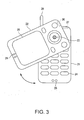
- Fig. 3 is a perspective overview of a rotating type mobile telephone handset to which the method of controlling wireless communication according to the invention is applied.
- buttons 24 are provided on a surface of a first case member 21, a microphone 25 is provided at the lower end of the first case member 21, and an external wireless communication antenna 26 is attached to the upper end of the first case member 21.
- a display part 28 is provided on the surface of the second case member 22, and a speaker 29 is provided at the upper end of the second case member 22.
- the first and second case members 21 and 22 are provided with internal wireless communication antennas 27 and 30, respectively for internal wireless communication between these members.
- the first and second case members 21 and 22 are coupled through a hinge 23.
- the second case member 22 When the second case member 22 is turned horizontally around the hinge 23, the second case member 22 may be placed on the first case member 21 or may be shifted from the first case member 21.
- the operation buttons 24 By placing the second case member 22 on the first case member 21, the operation buttons 24 can be protected by the second case member 22, so that the buttons 24 can be prevented from being accidentally operated while the user carries the mobile telephone around.
- the second case member 22 is turned horizontally to shift from the first case member 21, the user can operate the operation buttons 24 while looking at the display part 28 or speak with a party on the other end while using the speaker 29 and the microphone 25.
- data transmission between the first and second case members 21 and 22 can be carried out by internal wireless communication using the internal wireless communication antennas 27 and 30.
- image data or audio data obtained into the first case member 21 through the external wireless communication antenna 26 may be transmitted to the second case member 22 by internal wireless communication using the internal wireless communication antennas 27 and 30, so that images can be displayed at the display part 28, or audio sounds can be output from the speaker 29.
- the structure of the hinge 23 can be prevented from being complicated, and the packaging process can be prevented from being complicated. This allows the size of the mobile telephone to be reduced and the reliability to be improved while keeping the cost low.
- the mobile telephone may have a larger screen and an increased number of functions without impairing its portability.
- the mobile telephone has been described by way of illustration, but the invention may be applied to a video camera, a PDA (Personal Digital Assistance), a notebook type personal computer, and the like.
- a video camera a PDA (Personal Digital Assistance)
- PDA Personal Digital Assistance
- notebook type personal computer a notebook type personal computer
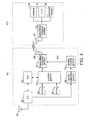
- Fig. 4 is a schematic block diagram of the configuration of a wireless communication terminal according to a first embodiment of the invention.
- a first case member K11 includes an external wireless communication antenna 101 that transmits/receives waves for external wireless communication, a wireless portion 102 that modulates/demodulates a signal transmitted/received through the external wireless communication antenna 101, a base band signal processing portion 103 that carries out base band signal processing, a control portion 104 that controls the wireless communication terminal as a whole, a RAM 105 that provides the control portion 104 with a work area for carrying out processing and stores the result of processing, a ROM 106 that stores various control programs used to operate the wireless communication terminal, a transmitting/receiving portion 107 that controls the internal wireless communication carried out through the internal wireless communication antenna 108, an internal wireless communication antenna 108 that transmits/receives waves for internal wireless communication on the side of the first case member K11, a carrier detecting portion 109 that detects the output level of the wireless portion 102, and an electric power control portion 110 that instructs the transmitting/receiving portion 107 to control the output power of the waves transmitted through
- the transmission power of the internal wireless communication carried out at the time of transmission by external wireless communication can be set larger than the transmission power of internal wireless communication carried out at the time of reception by external wireless communication.
- the second case member K12 includes a transmitting/receiving portion 121 that controls the internal wireless communication carried out through an internal wireless communication antenna 122, the internal wireless communication antenna 122 that transmits/receives waves for internal wireless communication on the side of the first case member K12, a camera 123 that carries out image-sensing, a liquid crystal display 124 that displays display data, and an additional device 125.
- the data transmitted/received by external wireless communication is, for example, audio data during telephone communication, character data and image data during e-mailing, and the like.
- the data transmitted/received by internal wireless communication is, for example, photographic data taken by the camera 123, display data to be displayed on the liquid crystal display 124 or a control signal used to control the second case member K12.
- the control portion 104 may be a CPU.
- the additional device 125 may be, for example, an LED, a microphone, or a speaker.
- the first and second case members K11 and K12 are coupled such that the positional relation between the first and second case members K11 and K12 can be changed.
- the positional relation between the first and second case members K11 and K12 may be changed by folding the second case member K12 onto the first case member K11, by horizontally turning the second case member K12 on the first case member K11, or by sliding the second case member K12 on the first case member K11 from side to side or backward/forward.
- the transmission data transmitted to the base band signal processing portion 103 is subjected to base-band signal processing.
- the transmission data output from the base band signal processing portion 103 is modulated by the wireless portion 102, and the resulting data is externally transmitted through the external wireless communication antenna 101.
- the data received through the external wireless communication antenna 101 is transmitted to the wireless portion 102, where the data is demodulated.
- the reception data output from the wireless portion 102 is transmitted to the base band signal processing portion 103 and subjected to base band signal processing, and the resulting data is then output to the control portion 104.
- a signal transmitted/received from/at the wireless portion 102 is transmitted to the carrier detecting portion 109, where the input/output level of the wireless portion 102 is detected.
- the power control portion 110 determines whether the transmission or the reception is carried out by the external wireless communication based on the input/output level of the wireless portion 102.
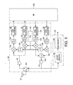
- Fig. 5 is a schematic block diagram of the configuration of the wireless portion 102 and the carrier detecting portion 109 in Fig. 4.
- the wireless portion 102 includes a switch 144, a low-noise amplifier 145, a power amplifier 132, mixers 146, 127, 133, and 137, filters 147, 128, 134, and 138, A/D converters 148, 129, D/A converters 135, 139, phase shifters 126 and 136, an adder 140, and a PLL circuit 141.
- the carrier detecting portion 109 is provided to detect the output level at the time of transmission.
- the carrier detecting portion 109 includes a power detector 142 and a comparator 143.
- the switch 144 is switched to the side of the low-noise amplifier 145.
- a signal received through the external wireless communication antenna 101 is transmitted to the mixers 146 and 127 through the low-noise amplifier 145.
- a local oscillation signal produced by the PLL circuit 141 is input to the mixer 146 through the phase shifter 126 and is directly input to the mixer 127.
- the signal output from the low-noise amplifier 145 is mixed with the phase-shifted local oscillation signal at the mixer 146, and then has a desired frequency component extracted by the filter 147.
- the signal then output from the filter 147 is digitized by the A/D converter 148, and then transmitted to the base band signal processing portion 103.
- the signal output from the low-noise amplifier 145 is mixed with the local oscillation signal at the mixer 127, and then has a desired frequency component extracted by the filter 128.
- the signal output from the filter 128 is digitized by the A/D converter 129, and then transmitted to the base band signal processing portion 103.
- the switch 144 is switched to the side of the power amplifier 132.
- Signals output from the base band signal processing portion 103 are converted into analog signals by the D/A converters 135 and 139 and then have desired frequency components extracted by the respective filters 134 and 138.
- the signals output from the respective filters 134 and 138 are transmitted to the mixers 133 and 137, respectively.
- a local oscillation signal generated by the PLL circuit 141 is input to the mixer 133 through the phase shifter 136, and is directly input to the mixer 137.
- the signal output from the filter 134 is mixed with the phase-shifted local oscillation signal at the mixer 133 and then transferred to the adder 140.
- the signal output from the filter 138 is mixed with the local oscillation signal at the mixer 137 and then transmitted to the adder 140. After the signals output from the mixers 133 and 137 are added at the adder 140 and then transmitted to the external wireless communication antenna 101 through the power amplifier 122 and externally output through the external wireless communication antenna 101.
- the signal output from the power amplifier 132 is transmitted to the power director 142, where the transmission output level is detected.
- the output level detected by the power detector 142 is compared to a reference value at a comparator 143, and then, the result of comparison is transmitted to the power control portion 110 in Fig. 4.
- the power control portion 110 determines whether the transmission or the reception is carried out by the external wireless communication based on the output level detected by the carrier detecting portion 109 once the output level at the time of external wireless communication is detected by the carrier detecting portion 109. If the transmission is carried out by the external wireless communication, the power control portion 110 can instruct the transmitting/receiving portion 107 to raise the transmission power of the internal wireless communication, and if the reception is carried out by the external wireless communication, the control portion 110 can instruct the transmitting/receiving portion 107 to lower the transmission power of the internal wireless communication. Note that when neither transmission nor reception is carried out by the external wireless communication, the power control portion 110 can issue an instruction so that the transmission power of the internal wireless communication is equal to or lower than the transmission power of the internal wireless communication when the reception is carried out by the external wireless communication.
- TDMA Time Division Multiple Access
- one frequency band is segmented by prescribed time intervals, and a plurality of users can share one frequency band for each prescribed period. More specifically, the frequency band is divided by time intervals, and allocated to the respective wireless communication terminals, and the users can use the entire band width within the allocated time period.
- the respective wireless communication terminals can continuously and periodically transmit signals.
- Figs. 6 are timing charts for use in illustration of a method of controlling internal communication at the wireless communication terminal in Fig. 4.
- the carrier detecting portion 109 in Fig. 4 can monitor the input/output level of the wireless portion 102 to detect the transmission timing allocated to the user wireless communication terminal.
- the power control portion 110 can generate a transmission timing signal S11 based on the output level detected by the carrier detecting portion 109 and output the transmission timing signal S11 to the transmitting/receiving portion 107.
- the transmitting/receiving portion 107 can transmit image data or audio data transmitted from the control portion 104 while the output power of the waves output from the internal wireless communication antenna 108 is raised as shown in Fig. 6(c).
- the image data or audio data transmitted through the internal wireless communication antenna 108 is received through the internal wireless communication antenna 122.
- the transmitting/receiving portion 121 can make the liquid crystal display part 124 display the image data received through the internal wireless communication antenna 122 or the speaker output the audio data received through the internal wireless communication antenna 122.
- Fig. 7 includes graphs for use in illustration of how to set transmission power according to an embodiment of the invention.
- the power transmitted through the internal wireless communication antenna 108 at the time of reception by the external wireless communication is set to -60 dBm so that the power does not interfere with the reception by the external wireless communication.
- the power transmitted through the external wireless communication antenna 101 is +30 dBm. If the interference by the external wireless communication can be attenuated by 70 dB by the filtering characteristic F and the interference by the external wireless communication can be attenuated by 10 dB by shielding, the power transmitted through the internal wireless communication antenna 108 at the time of transmission by the external wireless communication is increased by only 20 dB, so that the interference by the external wireless communication can be reduced while the internal wireless communication can stably be carried out with the margin of 10 dB.
- the power transmitted through the internal wireless communication antenna 108 is returned to the original -60 dBm, so that the effect of the internal wireless communication upon the receiving operation by the external wireless communication can be reduced.
- the effect of the waves by the external wireless communication is smaller than at the time of transmission by the external wireless communication, and therefore the communication quality of the internal wireless communication can be secured even if the output power by the internal wireless communication is small.
- a mobile telephone is a specific example of a wireless communication terminal. Therefore, also when the clamshell design is employed for a mobile telephone, data transmission between the first and second case members K11 and K12 can stably be carried out by wireless. As a result, even if the quantity of data exchanged between the first and second case members K11 and k12 increases as the resolution of the liquid crystal display part 124 provided in the mobile telephone and the screen size thereof increase, the increase in the number of interconnections between the first and second case members K11 and k12 can be reduced. This prevents the hinge structure and the packaging process from being complicated.
- very weak radio or close range radio by UWB radio may be employed.
- the internal wireless communication can stably be carried out while the output level of the internal wireless communication can be reduced. Therefore, even if the data transmission quantity between the first and second case members K11 and K12 increases, the data transmission between them can be carried out by wireless within the legal restrictions, and therefore the increase in the number of interconnections between the first and second case members K11 and K12 can be reduced.
- the power control portion 110 may output the transmission timing signal to both the transmitting/receiving portions 107 and 121.
- the transmitting/receiving portion 121 may raise the transmission power of the internal wireless communication carried out through the internal wireless communication antenna 122 at the time of transmission by the external wireless communication.
- TDMA has been described as the method for the external wireless communication by way of illustration, but a multiple access method such as FDMA (Frequency Division Multiple Access) and CDMA (Code Division Multiple Access) may be applied other than TDMA.
- FDMA Frequency Division Multiple Access
- CDMA Code Division Multiple Access
- Fig. 8 is a schematic block diagram of the configuration of a wireless communication terminal according to a second embodiment of the invention.
- a first case member K31 includes an external wireless communication antenna 301, a wireless portion 302, a base band signal processing portion 303, a control portion 304, a RAM 305, a ROM 306, a transmitting/receiving portion 307, an internal wireless communication antenna 308, a carrier detecting portion 309, a power control portion 310, and a carrier detecting antenna 311.
- a second case member K32 includes a transmitting/receiving portion 321, an internal wireless communication antenna 322, a camera 323, a liquid crystal display 324, and an additional device 325. The first and second case members K31 and K32 are hinged together such that their positional relation can be changed.
- Waves transmitted through the external wireless communication antenna 301 are received by the carrier detecting antenna 311, and a carrier detection signal is transmitted to the carrier detecting portion 309.
- the carrier detecting portion 309 Upon receiving the carrier detection signal received by the carrier detecting antenna 311, the carrier detecting portion 309 detects the output level of the carrier detection signal and outputs the determination result to the power control portion 310.
- the power control portion 310 generates a transmission timing signal S31 based on the output level detected by the carrier detecting portion 309 and outputs the transmission timing signal S31 to the transmitting/receiving portion 307.
- the transmitting/receiving portion 307 can carry out internal wireless communication between the first and second case members K31 and k32 while the output power of the waves output from the internal wireless communication antenna 308 is raised.
- the output level of the waves transmitted through the external wireless communication antenna 301 can directly be monitored and it can be determined whether or not the waves are transmitted through the external wireless communication antenna 301. Therefore, according to the transmission timing for the external wireless communication, the transmission power of the internal wireless communication can be controlled, and therefore the cost can be prevented from increasing, while the size of the wireless communication terminal can be reduced and the reliability of the terminal can be improved. Meanwhile, the size of the screen of the wireless communication terminal can be increased and the number of functions carried out by the terminal can be increased while the portability of the terminal is not impaired.
- Fig. 9 is a schematic block diagram of the configuration of a wireless communication terminal according to a third embodiment of the invention.
- a first case member K41 includes an external wireless communication antenna 401, a wireless portion 402, a base band signal processing portion 403, a control portion 404, a RAM 405, a ROM 406, a transmitting/receiving portion 407, an internal wireless communication antenna 408, and a power control portion 410.
- a second case member K42 includes a transmitting/receiving portion 421, an internal wireless communication antenna 422, a camera 423, a liquid crystal display 424, and an additional device 425. The first and second case members K41 and K42 are coupled such that their positional relation can be changed.
- the control portion 404 transmits transmission data to the base band signal processing portion 403 and notifies the power control portion 410 of the transmission timing at the time of transmitting the data.
- the base band signal processing portion 403 carries out base band signal processing of the transmission data from the control portion 404 and outputs the resulting data to the wireless portion 402.
- the wireless portion 402 modulates the transmission data and externally outputs the resulting signal through the external wireless communication antenna 401.
- the power control portion 410 When the power control portion 410 is notified of the transmitting timing for the transmission data from the control portion 404, the power control portion 410 generates a transmission timing signal S41 and outputs the generated transmission timing signal S41 to the transmitting/receiving portion 407. Upon receiving the transmission timing signal S41 from the power control portion 410, the transmitting/receiving portion 407 can carry out internal wireless communication between the first and second case members K41 and K42 while the output power of the waves output from the internal wireless communication antenna 408 is raised.
- the transmission power of the internal wireless communication can be controlled in response to the transmission timing for the external wireless communication.
- the size of the wireless communication terminal can be reduced and the reliability can be improved while preventing the cost from increasing.
- the screen size of the wireless communication terminal and the number of functions can be increased without impairing the portability of the wireless communication terminal.
- the communication protocol with the outside may be determined in advance based on the operation mode such as waiting, speaking, and packet telecommunication. Therefore, the control portion 404 can obtain the transmission/reception timing in advance when, for example, TDMA or packet communication is carried out. Therefore, the power control portion 410 may control the output power of waves output from the internal wireless communication antenna 408 based on the time schedule determined according to the transmission/reception timings for the external wireless communication.
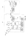
- Fig. 10 is a block diagram of the configuration of a wireless communication terminal according to a fourth embodiment of the invention.
- a first case member K51 includes an external wireless communication antenna 501, a wireless portion 502, a base band signal processing portion 503, a control portion 504, a RAM 505, a ROM 506, a transmitting/receiving portion 507, an internal wireless communication antenna 508, a communication environment detecting portion 509, and a power control portions 510 and 511.
- a second case member K52 includes a transmitting/receiving portion 521, an internal wireless communication antenna 522, a camera 523, a liquid crystal display 524, and an additional device 525. The first and second case members K51 and K52 are coupled such that their positional relation can be changed.
- the communication environment detecting portion 509 detects a communication environment based on a reception signal received through the external wireless communication antenna 501.
- the communication environment may be detected based on the bit error rate for digital signals, and based on the signal-to-noise ratio or distortion factor for analog signals.
- the power control portion 511 controls the output power of waves transmitted from the external wireless communication antenna 501 based on the communication environment detected by the communication environment detecting portion 509.
- the power control portion 510 controls the output power of waves transmitted from the internal wireless communication antenna 508 based on the control result by the power control portion 511.
- the control portion 504 When data is transmitted through the external wireless communication antenna 501, the control portion 504 notifies the power control portion 510 of the transmission timing for transmitting the transmission data. When the power control portion 510 is notified of the transmission timing for the transmission data from the control portion 504, the power control portion 510 generates a transmission timing signal S51 and outputs the generated transmission timing signal S51 to the transmitting/receiving portion 507. Upon receiving the transmission timing signal S51 from the power control portion 510, the transmitting/receiving portion 507 can carry out internal wireless communication between the first and second case members K51 and K52 while the output power of the waves output from the internal wireless communication antenna 408 is raised.
- the power control portion 511 instructs the wireless portion 502 to raise the output power of the waves output from the external wireless communication antenna 501.
- the wireless portion 502 raises the output power of waves output from the external wireless communication antenna 501.
- the power control portion 511 instructs the power control portion 510 to raise the output power of waves output from the internal wireless communication antenna 508.
- the power control portion 510 instructs the transmitting/receiving portion 507 to raise the output power of waves output from the external wireless communication antenna 508.
- the transmitting/receiving portion 507 can raise the output power of waves output from the internal wireless communication antenna 508 by an amount corresponding to the increase in the output power of waves output from the external wireless communication antenna 501.
- the transmission power of the external wireless communication can be controlled based on the communication environment, and the transmission power of the internal wireless communication can be increased based on the transmission power of the external wireless communication. Therefore, the quality of the internal wireless communication can be kept less degraded while the quality of the external wireless communication can be improved.
Landscapes
- Engineering & Computer Science (AREA)
- Signal Processing (AREA)
- Telephone Function (AREA)
- Transceivers (AREA)
- Mobile Radio Communication Systems (AREA)
Abstract
A power control portion 110 determines whether transmission or reception is carried out by an external wireless communication based on the input/output level of a wireless portion 102 detected by the carrier detecting portion 109. If the transmission is carried out by the external wireless communication, the power control portion 110 can instruct a transmitting/receiving portion 107 to raise the transmission power of internal wireless communication, and if the reception is carried out by the external wireless communication, the power control portion 110 can instruct the transmitting/receiving portion 107 to lower the transmission power of the internal wireless communication.
Description
- The present invention relates to a wireless communication terminal and a mobile type wireless communication terminal, and is particularly applicable to a clamshell type mobile telephone and the like.
- In recent years, there have been attempts to increase the resolution of liquid crystal displays equipped in the mobile telephones so that, in addition to normal still images such as characters and graphics, still pictures or moving images taken by digital cameras can be displayed with higher definition. This increases the volume of data exchanged between the digital camera and the liquid crystal display and the use of LVDS (Low Voltage Differential Signaling), a high speed transfer system for connection with a display part or an image sensing device has been proposed.
- Recent mobile telephone handsets mostly employ the clamshell design because its foldable structure allows the mobile telephones to have a larger display size while their portability is not impaired and the design can prevent operation buttons from being accidentally pressed while the users carry the handsets around. The clamshell design has a first case member including a control portion that mainly controls the external wireless communication function of the mobile telephone and a second case member having a display part. The first and second case members are hinged together and can be opened and closed through the hinge.
- However, as the resolution of the display part placed in the mobile telephone increases, the number of pins in a flexible wiring board used for sending signals to the display part must be increased in order to transmit high bit rate image data or the like to the display part through a wire. Therefore, in a mobile telephone handset with a clamshell design, the flexible wiring board with an increased number of pins must be passed through the hinge in the case of carrying out the - data transmission between the first and second case members through a wire. This is not only an obstacle to reduce the size of the mobile telephone handset, but also pushes up the cost, and the reliability can be lowered.
- Meanwhile, instead of the flexible wiring board, an internal wireless communication antenna may be provided in each of the first and second case members, so that data transmission between the first and second case members can be carried out by internal wireless communication. In this case, the communication suffers from interference with wireless communication outside the mobile telephone. Therefore, the environment for the internal wireless communication changes depending on the wireless communication outside the mobile telephone, and the reliability in surely transmitting data can be deteriorated.
- When a wireless communication method operating with low limited output by UWB (Ultra Wide Band) is employed for the internal wireless communication in particular, the power level is greatly different from the waves output by the wireless communication outside the mobile telephone, and the power level difference could be as large as 90 dB.
- Therefore, the effect of even a signal outside the band of interest upon the internal wireless communication could not be ignored, the interference with the wireless communication outside the mobile telephone degrades the wireless communication environment, the bit error rate increases and retransmission caused by increase in the packet error rate could be increased.
- According to a method disclosed by
JP-T-2003-507954 - According to the method disclosed by
JP-T-2003-507954 - An object of the invention is to provide a wireless communication terminal and a mobile wireless communication terminal that allow the communication environment to be changed by external wireless communication and reduce the deterioration in the quality of the internal wireless communication between first and second case members.
- In order to solve the problems, a wireless communication terminal according to one aspect of the invention includes a first case member, a second case member coupled with the first case member, a coupling portion that couples the first and second case members so that the positional relation between the first and second case members can be changed, an external wireless communication antenna, an external wireless communication control portion that mainly controls external wireless communication carried out through the external wireless communication antenna, a first internal wireless communication antenna, a first internal wireless communication control portion that controls internal wireless communication carried out through the first internal wireless communication antenna, the external wireless communication antenna, the external wireless communication control portion, the first internal wireless communication antenna and the first internal wireless communication control portion being provided at the first case member, a display part, a second internal wireless communication antenna, a second internal wireless communication control portion that controls internal wireless communication carried out through the second internal wireless communication antenna, the display part, the second internal wireless communication antenna and the second internal wireless communication control portion being provided at the second case member, and an output power control portion that controls the output power of waves transmitted by the internal wireless communication based on the timing of transmitting waves transmitted through the external wireless communication antenna.
- In this way, the transmission power of the internal wireless communication carried out between the first and second case members can be controlled depending on the power handled by the external wireless communication. Therefore, while the effect of the external wireless communication upon the quality is reduced, the internal wireless communication can be carried out. Even if the effect of interference by the external wireless communication is great, the deterioration in the quality of the internal wireless communication can be reduced. Therefore, the communication quality in both the external and internal wireless communication can be secured, while the data transmission between the first and second case members can be carried out by wireless. Consequently, even if the data transmission quantity between the first and second case members increases, the positional relation between the first and second case members can be changed without complicating the structure of the coupling portion. Therefore, the size of the wireless communication terminal can be reduced and the reliability can be improved while the increase in the cost is kept low. In addition, the wireless communication terminal may have a larger screen and can carry out an increased number of functions while the portability of the wireless communication terminal is not impaired.
- A wireless communication terminal according to another aspect of the invention includes a first case member, a second case member, a coupling portion that couples the first and second case members such that the positional relation between the first and second case members can be changed, an external wireless communication antenna, an external wireless communication control portion that mainly controls external wireless communication carried out through the external wireless communication antenna, a first internal wireless communication antenna, a first internal wireless communication control portion that controls internal wireless communication carried out through the first internal wireless communication antenna, the external wireless communication antenna, the external wireless communication control portion, the first internal wireless communication antenna and the first internal wireless communication control portion being provided at the first case member, a display part, a second internal wireless communication antenna, a second internal wireless communication control portion that controls internal wireless communication carried out through the second internal wireless communication antenna, the display part, the second internal wireless communication antenna and the second internal wireless communication control portion being provided at the second case member, a carrier detecting portion that detects the output level of waves transmitted from the external wireless communication antenna, and an output power control portion that controls the output power of waves transmitted from at least one of the first and second internal wireless communication antennas based on the output level detected by the carrier detecting portion.
- In this way, the output level of waves transmitted through the external wireless communication antenna can directly be monitored, and it can be determined whether or not the waves are transmitted through the external wireless communication antenna. Therefore, according to the transmission timing for the external wireless communication, the transmission power of the internal wireless communication can be controlled, and the cost can be prevented from increasing, while the size of the wireless communication terminal can be reduced and the reliability of the terminal can be improved. Meanwhile, the screen size of the wireless communication terminal can be increased and the number of functions carried out by the terminal can be increased while the portability of the terminal is not impaired.
- According to a wireless communication terminal regarding another aspect of the invention, the output power control portion sets the transmission power of the internal wireless communication carried out at the time of transmission by the external wireless communication to be larger than the transmission power of the internal wireless communication carried out at the time of reception by the external wireless communication.
- In this way, when the power handled by the external wireless communication is large, the transmission power of the internal wireless communication can be increased. At the time of receiving by the external wireless communication, the transmission power of the internal wireless communication can be reduced. Therefore, while the deterioration in the quality of the internal wireless communication can be reduced, the transmission operation by the external wireless communication can be carried out. In addition, the internal wireless communication can be carried out without affecting the receiving operation by the external wireless communication.
- A wireless communication terminal according to yet another aspect of the invention includes a first case member, a second case member, a coupling portion that couples the first and second case members such that the positional relation between the first and second case members can be changed, an external wireless communication antenna, an external wireless communication control portion that mainly controls external wireless communication carried out through the external wireless communication antenna, a first internal wireless communication antenna, a first internal wireless communication control portion that controls internal wireless communication carried out through the first internal wireless communication antenna, the external wireless communication antenna, the external wireless communication control portion, the first internal wireless communication antenna and the first internal wireless communication control portion being provided at the first case member, a display part, a second internal wireless communication antenna, a second internal wireless communication control portion that controls internal wireless communication carried out through the second internal wireless communication antenna, the display part, the second internal wireless communication antenna and the second internal wireless communication control portion being provided at the second case member, a communication environment detecting portion that detects a communication environment based on a signal received through the external wireless communication antenna, a first output power control portion that controls the output power of waves transmitted from the external wireless communication antenna based on the communication environment detected by the communication environment detecting portion, and a second output power control portion that controls the output power of waves transmitted from at least one of the first and second internal wireless communication antennas based on the result of control by the first output power control portion.
- In this way, the transmission power of the external wireless communication can be controlled based on the communication environment, while the transmission power of the internal wireless communication can be increased based on the transmission power of the external wireless communication. In this way, the deterioration in the quality of the internal wireless communication can be reduced while the quality of the external wireless communication can be improved.
- According to a wireless communication terminal regarding yet another aspect of the invention, the wireless communication terminal is a mobile telephone.
- Therefore, when a clamshell design is employed for the mobile telephone, the data transmission between the case members of the mobile telephone can be carried out stably by wireless. In this way, even if the quantity of data exchanged between the case members increases to cope with a display part with higher resolution provided in the mobile telephone, the structure of the coupling portion and the packaging process can be prevented from being complicated. Consequently, the size of the mobile telephone can be reduced and the reliability of the telephone can be improved while the increase in the cost is kept low. In addition, the size of screen of the mobile telephone and the number of functions carried out by the telephone can be increased while the portability of the telephone is not impaired.
- According to a wireless communication terminal regarding a still further aspect of the invention, the internal wireless communication is very weak radio or close range radio by UWB radio.
- In this way, while the output level of the internal wireless communication is reduced, the internal wireless communication can be carried out stably. Therefore, even if the quantity of data transmission between the first and second case members increases, the data transmission between them can be carried out by wireless within legal restrictions, and therefore the positional relation between the first and second case members can be changed without complicating the structure of the coupling portion.
- In a mobile type wireless communication terminal according to a still further aspect of the invention, two case members are coupled such that the relative position between the two case members can be changed. The terminal includes an internal wireless communication portion that transmits/receives data between the two case members, and an external wireless communication portion that communicates with an external device by wireless provided in at least one of the two case members. The transmission power of the internal wireless communication carried out at the time of transmission by the external wireless communication is larger than the transmission power of the internal wireless communication carried out at the time of reception by the external wireless communication.
- In this way, the adverse effect of interference between the internal and external wireless communication can be reduced. Consequently, the deterioration in the quality of the internal wireless communication between the case members can be reduced while allowing the communication environment to be changed according to the external wireless communication, and the increase in the quantity of data transmission between the case members can be addressed while the flexibility in the positional relation between the case members is secured.
-
- Fig. 1 is a perspective view showing the state of a clamshell type mobile telephone handset to which a method of controlling wireless communication according to the invention is applied as the handset is open.
- Fig. 2 is a perspective view showing the state of the clamshell type mobile telephone handset to which the method of controlling wireless communication according to the invention is applied as the handset is closed.
- Fig. 3 is a perspective overview of a rotating type mobile telephone handset to which the method of controlling wireless communication according to the invention is applied.
- Fig. 4 is a schematic block diagram of the configuration of a wireless communication terminal according to a first embodiment of the invention.
- Fig. 5 is a schematic block diagram of the configuration of a wireless portion and a carrier detecting portion in Fig. 4.
- Figs. 6 are timing charts for use in illustration of a method of controlling the internal communication in the wireless communication terminal in Fig. 4.
- Fig. 7 includes graphs for use in illustration of how to set transmission power according to an embodiment of the invention.
- Fig. 8 is a schematic block diagram of the configuration of a wireless communication terminal according to a second embodiment of the invention.
- Fig. 9 is a schematic block diagram of the configuration of a wireless communication terminal according to a third embodiment of the invention.
- Fig. 10 is a block diagram of the configuration of a wireless communication terminal according to a fourth embodiment of the invention.
- Hereinafter, a wireless communication terminal and a method of controlling wireless communication according to embodiments of the invention will be described with reference to the drawings.
- Fig. 1 is a perspective view showing the state of a clamshell type mobile telephone handset to which a method of controlling wireless communication according to the invention is applied as the handset is opened. Fig. 2 is a perspective view showing the state of the clamshell type mobile telephone handset to which a method of controlling wireless communication according to the invention is applied as the handset is closed.
- In Figs. 1 and 2,
operation buttons 4 are provided on the surface of afirst case member 1, amicrophone 5 is provided at the lower end of thefirst case member 1, and an externalwireless communication antenna 6 is provided on the upper end of thefirst case member 1. Adisplay part 8 is provided on the surface of asecond case member 2 and a speaker 9 is provided at the upper end of thesecond case member 2. There are adisplay part 11 and an image-sensingdevice 12 provided on the back surface of thesecond case member 2. Note that as thedisplay parts device 12, a CCD or a CMOS sensor may be used. The first andsecond case members - The first and
second case members hinge 3, and thesecond case member 2 can be folded onto thefirst case member 1 by pivoting thesecond case member 2 around thehinge 3. By closing thesecond case member 2 onto thefirst case member 1, theoperation buttons 4 can be protected by thesecond case member 2, and thebuttons 4 can be prevented from being accidentally operated as the user carries the mobile telephone around. As thesecond case member 2 is unfolded from thefirst case member 1, the user can operate theoperation buttons 4 while looking at thedisplay part 8, speak with a party on the other end while using the speaker 9 and themicrophone 5, or capture an image while operating theoperation buttons 4. - In this way, the use of the clamshell design allows the
display part 8 to be provided almost entirely over one surface of thesecond case member 2, and therefore the size and the visibility of thedisplay part 8 can be increased without impairing the portability of the mobile telephone. - With the internal wireless communication antennas 7 and 10 provided in the first and
second case members second case members first case member 1 through the externalwireless communication antenna 6 may be transmitted to thesecond case member 2 by internal wireless communication using the internal wireless communication antennas 7 and 10, so that images may be displayed at thedisplay part 8, or audio sounds can be output from the speaker 9. Photographic data taken by the image-sensingdevice 12 may be transmitted from thesecond case member 2 to thefirst case member 1 by internal wireless communication using the internal wireless communication antennas 7 and 10 and externally output through the externalwireless communication antenna 6. - In this way, the use of wired data transmission between the first and
second case members hinge 3. Therefore, the structure of thehinge 3 and the packaging process can be prevented from being complicated. This allows the size of the mobile telephone to be reduced and the reliability to be improved while the cost increase is kept low. In addition, the mobile telephone may have a larger screen and an increased number of functions without impairing its portability. - Fig. 3 is a perspective overview of a rotating type mobile telephone handset to which the method of controlling wireless communication according to the invention is applied.
- In Fig. 3,
operation buttons 24 are provided on a surface of afirst case member 21, amicrophone 25 is provided at the lower end of thefirst case member 21, and an externalwireless communication antenna 26 is attached to the upper end of thefirst case member 21. Adisplay part 28 is provided on the surface of thesecond case member 22, and aspeaker 29 is provided at the upper end of thesecond case member 22. The first andsecond case members wireless communication antennas - The first and
second case members hinge 23. When thesecond case member 22 is turned horizontally around thehinge 23, thesecond case member 22 may be placed on thefirst case member 21 or may be shifted from thefirst case member 21. By placing thesecond case member 22 on thefirst case member 21, theoperation buttons 24 can be protected by thesecond case member 22, so that thebuttons 24 can be prevented from being accidentally operated while the user carries the mobile telephone around. As thesecond case member 22 is turned horizontally to shift from thefirst case member 21, the user can operate theoperation buttons 24 while looking at thedisplay part 28 or speak with a party on the other end while using thespeaker 29 and themicrophone 25. - In this way, with the internal
wireless communication antennas second case members second case members wireless communication antennas first case member 21 through the externalwireless communication antenna 26 may be transmitted to thesecond case member 22 by internal wireless communication using the internalwireless communication antennas display part 28, or audio sounds can be output from thespeaker 29. - In this way, a flexible wiring board with a large number of pins does not have to be passed through the
hinge 23. Therefore, the structure of thehinge 23 can be prevented from being complicated, and the packaging process can be prevented from being complicated. This allows the size of the mobile telephone to be reduced and the reliability to be improved while keeping the cost low. In addition, the mobile telephone may have a larger screen and an increased number of functions without impairing its portability. - Note that according to the above-described embodiment, the mobile telephone has been described by way of illustration, but the invention may be applied to a video camera, a PDA (Personal Digital Assistance), a notebook type personal computer, and the like.
- Fig. 4 is a schematic block diagram of the configuration of a wireless communication terminal according to a first embodiment of the invention.
- In Fig. 4, a first case member K11 includes an external
wireless communication antenna 101 that transmits/receives waves for external wireless communication, awireless portion 102 that modulates/demodulates a signal transmitted/received through the externalwireless communication antenna 101, a base bandsignal processing portion 103 that carries out base band signal processing, acontrol portion 104 that controls the wireless communication terminal as a whole, aRAM 105 that provides thecontrol portion 104 with a work area for carrying out processing and stores the result of processing, aROM 106 that stores various control programs used to operate the wireless communication terminal, a transmitting/receivingportion 107 that controls the internal wireless communication carried out through the internalwireless communication antenna 108, an internalwireless communication antenna 108 that transmits/receives waves for internal wireless communication on the side of the first case member K11, acarrier detecting portion 109 that detects the output level of thewireless portion 102, and an electricpower control portion 110 that instructs the transmitting/receivingportion 107 to control the output power of the waves transmitted through the internalwireless communication antenna 108 based on the output level detected by thecarrier detecting portion 109. - Note that when the output power of the waves transmitted through the internal
wireless communication antenna 108 is controlled, the transmission power of the internal wireless communication carried out at the time of transmission by external wireless communication can be set larger than the transmission power of internal wireless communication carried out at the time of reception by external wireless communication. - The second case member K12 includes a transmitting/receiving
portion 121 that controls the internal wireless communication carried out through an internalwireless communication antenna 122, the internalwireless communication antenna 122 that transmits/receives waves for internal wireless communication on the side of the first case member K12, acamera 123 that carries out image-sensing, aliquid crystal display 124 that displays display data, and anadditional device 125. Note that the data transmitted/received by external wireless communication is, for example, audio data during telephone communication, character data and image data during e-mailing, and the like. The data transmitted/received by internal wireless communication is, for example, photographic data taken by thecamera 123, display data to be displayed on theliquid crystal display 124 or a control signal used to control the second case member K12. Thecontrol portion 104 may be a CPU. Theadditional device 125 may be, for example, an LED, a microphone, or a speaker. - The first and second case members K11 and K12 are coupled such that the positional relation between the first and second case members K11 and K12 can be changed. Note that the positional relation between the first and second case members K11 and K12 may be changed by folding the second case member K12 onto the first case member K11, by horizontally turning the second case member K12 on the first case member K11, or by sliding the second case member K12 on the first case member K11 from side to side or backward/forward.
- When data is transmitted through the external
wireless communication antenna 101, the transmission data transmitted to the base bandsignal processing portion 103 is subjected to base-band signal processing. The transmission data output from the base bandsignal processing portion 103 is modulated by thewireless portion 102, and the resulting data is externally transmitted through the externalwireless communication antenna 101. Meanwhile, when data is received through the externalwireless communication antenna 101, the data received through the externalwireless communication antenna 101 is transmitted to thewireless portion 102, where the data is demodulated. The reception data output from thewireless portion 102 is transmitted to the base bandsignal processing portion 103 and subjected to base band signal processing, and the resulting data is then output to thecontrol portion 104. - In this case, a signal transmitted/received from/at the
wireless portion 102 is transmitted to thecarrier detecting portion 109, where the input/output level of thewireless portion 102 is detected. Thepower control portion 110 then determines whether the transmission or the reception is carried out by the external wireless communication based on the input/output level of thewireless portion 102. - Fig. 5 is a schematic block diagram of the configuration of the
wireless portion 102 and thecarrier detecting portion 109 in Fig. 4. - In Fig. 5, the
wireless portion 102 includes aswitch 144, a low-noise amplifier 145, apower amplifier 132,mixers filters D converters A converters phase shifters adder 140, and a PLL circuit 141. Thecarrier detecting portion 109 is provided to detect the output level at the time of transmission. Thecarrier detecting portion 109 includes apower detector 142 and acomparator 143. - At the time of reception, the
switch 144 is switched to the side of the low-noise amplifier 145. A signal received through the externalwireless communication antenna 101 is transmitted to themixers noise amplifier 145. Here, a local oscillation signal produced by the PLL circuit 141 is input to themixer 146 through thephase shifter 126 and is directly input to themixer 127. - The signal output from the low-
noise amplifier 145 is mixed with the phase-shifted local oscillation signal at themixer 146, and then has a desired frequency component extracted by thefilter 147. The signal then output from thefilter 147 is digitized by the A/D converter 148, and then transmitted to the base bandsignal processing portion 103. The signal output from the low-noise amplifier 145 is mixed with the local oscillation signal at themixer 127, and then has a desired frequency component extracted by thefilter 128. The signal output from thefilter 128 is digitized by the A/D converter 129, and then transmitted to the base bandsignal processing portion 103. - Meanwhile, at the time of transmission, the
switch 144 is switched to the side of thepower amplifier 132. Signals output from the base bandsignal processing portion 103 are converted into analog signals by the D/A converters respective filters respective filters mixers 133 and 137, respectively. Here, a local oscillation signal generated by the PLL circuit 141 is input to themixer 133 through thephase shifter 136, and is directly input to the mixer 137. The signal output from thefilter 134 is mixed with the phase-shifted local oscillation signal at themixer 133 and then transferred to theadder 140. The signal output from thefilter 138 is mixed with the local oscillation signal at the mixer 137 and then transmitted to theadder 140. After the signals output from themixers 133 and 137 are added at theadder 140 and then transmitted to the externalwireless communication antenna 101 through thepower amplifier 122 and externally output through the externalwireless communication antenna 101. - The signal output from the
power amplifier 132 is transmitted to thepower director 142, where the transmission output level is detected. The output level detected by thepower detector 142 is compared to a reference value at acomparator 143, and then, the result of comparison is transmitted to thepower control portion 110 in Fig. 4. - The
power control portion 110 determines whether the transmission or the reception is carried out by the external wireless communication based on the output level detected by thecarrier detecting portion 109 once the output level at the time of external wireless communication is detected by thecarrier detecting portion 109. If the transmission is carried out by the external wireless communication, thepower control portion 110 can instruct the transmitting/receivingportion 107 to raise the transmission power of the internal wireless communication, and if the reception is carried out by the external wireless communication, thecontrol portion 110 can instruct the transmitting/receivingportion 107 to lower the transmission power of the internal wireless communication. Note that when neither transmission nor reception is carried out by the external wireless communication, thepower control portion 110 can issue an instruction so that the transmission power of the internal wireless communication is equal to or lower than the transmission power of the internal wireless communication when the reception is carried out by the external wireless communication. - In this case, as the communication method in the external wireless communication at the wireless communication terminal, TDMA (Time Division Multiple Access), a kind of multiple access method may be employed. By TDMA, one frequency band is segmented by prescribed time intervals, and a plurality of users can share one frequency band for each prescribed period. More specifically, the frequency band is divided by time intervals, and allocated to the respective wireless communication terminals, and the users can use the entire band width within the allocated time period. The respective wireless communication terminals can continuously and periodically transmit signals.
- Figs. 6 are timing charts for use in illustration of a method of controlling internal communication at the wireless communication terminal in Fig. 4.
- In Fig. 6(a), if, for example, a
slot 1 amongslots 1 to 4 represents the transmission timing allocated to the user wireless communication terminal, in theother slots 2 to 4, data is not transmitted from the user wireless communication terminal to the base station. Therefore, thecarrier detecting portion 109 in Fig. 4 can monitor the input/output level of thewireless portion 102 to detect the transmission timing allocated to the user wireless communication terminal. As shown in Fig. 6(b), thepower control portion 110 can generate a transmission timing signal S11 based on the output level detected by thecarrier detecting portion 109 and output the transmission timing signal S11 to the transmitting/receivingportion 107. Upon receiving the transmission timing signal S11 from thepower control portion 110, the transmitting/receivingportion 107 can transmit image data or audio data transmitted from thecontrol portion 104 while the output power of the waves output from the internalwireless communication antenna 108 is raised as shown in Fig. 6(c). The image data or audio data transmitted through the internalwireless communication antenna 108 is received through the internalwireless communication antenna 122. The transmitting/receivingportion 121 can make the liquidcrystal display part 124 display the image data received through the internalwireless communication antenna 122 or the speaker output the audio data received through the internalwireless communication antenna 122. - Fig. 7 includes graphs for use in illustration of how to set transmission power according to an embodiment of the invention.
- In Fig. 7, for example, the power transmitted through the internal
wireless communication antenna 108 at the time of reception by the external wireless communication is set to -60 dBm so that the power does not interfere with the reception by the external wireless communication. Meanwhile, the power transmitted through the externalwireless communication antenna 101 is +30 dBm. If the interference by the external wireless communication can be attenuated by 70 dB by the filtering characteristic F and the interference by the external wireless communication can be attenuated by 10 dB by shielding, the power transmitted through the internalwireless communication antenna 108 at the time of transmission by the external wireless communication is increased by only 20 dB, so that the interference by the external wireless communication can be reduced while the internal wireless communication can stably be carried out with the margin of 10 dB. - At the time of reception by the external wireless communication, the power transmitted through the internal
wireless communication antenna 108 is returned to the original -60 dBm, so that the effect of the internal wireless communication upon the receiving operation by the external wireless communication can be reduced. In this case, at the time of reception by the external wireless communication, the effect of the waves by the external wireless communication is smaller than at the time of transmission by the external wireless communication, and therefore the communication quality of the internal wireless communication can be secured even if the output power by the internal wireless communication is small. - Note that a mobile telephone is a specific example of a wireless communication terminal. Therefore, also when the clamshell design is employed for a mobile telephone, data transmission between the first and second case members K11 and K12 can stably be carried out by wireless. As a result, even if the quantity of data exchanged between the first and second case members K11 and k12 increases as the resolution of the liquid
crystal display part 124 provided in the mobile telephone and the screen size thereof increase, the increase in the number of interconnections between the first and second case members K11 and k12 can be reduced. This prevents the hinge structure and the packaging process from being complicated. - As the internal wireless communication using the internal wireless communication antennas 7 and 10, very weak radio or close range radio by UWB radio may be employed. In this way, the internal wireless communication can stably be carried out while the output level of the internal wireless communication can be reduced. Therefore, even if the data transmission quantity between the first and second case members K11 and K12 increases, the data transmission between them can be carried out by wireless within the legal restrictions, and therefore the increase in the number of interconnections between the first and second case members K11 and K12 can be reduced.
- Although a method of how the
power control portion 110 outputs the transmission timing signal S11 to the transmitting/receivingportion 107 has been described in the embodiment shown in Fig. 4, thepower control portion 110 may output the transmission timing signal to both the transmitting/receivingportions portion 121 may raise the transmission power of the internal wireless communication carried out through the internalwireless communication antenna 122 at the time of transmission by the external wireless communication. - According to the above-described embodiment, TDMA has been described as the method for the external wireless communication by way of illustration, but a multiple access method such as FDMA (Frequency Division Multiple Access) and CDMA (Code Division Multiple Access) may be applied other than TDMA.
- Fig. 8 is a schematic block diagram of the configuration of a wireless communication terminal according to a second embodiment of the invention.
- In Fig. 8, a first case member K31 includes an external
wireless communication antenna 301, awireless portion 302, a base bandsignal processing portion 303, acontrol portion 304, aRAM 305, aROM 306, a transmitting/receivingportion 307, an internalwireless communication antenna 308, acarrier detecting portion 309, apower control portion 310, and acarrier detecting antenna 311. A second case member K32 includes a transmitting/receivingportion 321, an internalwireless communication antenna 322, acamera 323, aliquid crystal display 324, and anadditional device 325. The first and second case members K31 and K32 are hinged together such that their positional relation can be changed. - Waves transmitted through the external
wireless communication antenna 301 are received by thecarrier detecting antenna 311, and a carrier detection signal is transmitted to thecarrier detecting portion 309. Upon receiving the carrier detection signal received by thecarrier detecting antenna 311, thecarrier detecting portion 309 detects the output level of the carrier detection signal and outputs the determination result to thepower control portion 310. - The
power control portion 310 generates a transmission timing signal S31 based on the output level detected by thecarrier detecting portion 309 and outputs the transmission timing signal S31 to the transmitting/receivingportion 307. Upon receiving the transmission timing signal S31 from thepower control portion 310, the transmitting/receivingportion 307 can carry out internal wireless communication between the first and second case members K31 and k32 while the output power of the waves output from the internalwireless communication antenna 308 is raised. - In this way, the output level of the waves transmitted through the external
wireless communication antenna 301 can directly be monitored and it can be determined whether or not the waves are transmitted through the externalwireless communication antenna 301. Therefore, according to the transmission timing for the external wireless communication, the transmission power of the internal wireless communication can be controlled, and therefore the cost can be prevented from increasing, while the size of the wireless communication terminal can be reduced and the reliability of the terminal can be improved. Meanwhile, the size of the screen of the wireless communication terminal can be increased and the number of functions carried out by the terminal can be increased while the portability of the terminal is not impaired. - Fig. 9 is a schematic block diagram of the configuration of a wireless communication terminal according to a third embodiment of the invention.
- In Fig. 9, a first case member K41 includes an external
wireless communication antenna 401, awireless portion 402, a base bandsignal processing portion 403, acontrol portion 404, aRAM 405, aROM 406, a transmitting/receivingportion 407, an internalwireless communication antenna 408, and apower control portion 410. A second case member K42 includes a transmitting/receivingportion 421, an internalwireless communication antenna 422, acamera 423, aliquid crystal display 424, and an additional device 425. The first and second case members K41 and K42 are coupled such that their positional relation can be changed. - When data is transmitted through the external
wireless communication antenna 401, thecontrol portion 404 transmits transmission data to the base bandsignal processing portion 403 and notifies thepower control portion 410 of the transmission timing at the time of transmitting the data. The base bandsignal processing portion 403 carries out base band signal processing of the transmission data from thecontrol portion 404 and outputs the resulting data to thewireless portion 402. Upon receiving the transmission data after the base band signal processing, thewireless portion 402 modulates the transmission data and externally outputs the resulting signal through the externalwireless communication antenna 401. - When the
power control portion 410 is notified of the transmitting timing for the transmission data from thecontrol portion 404, thepower control portion 410 generates a transmission timing signal S41 and outputs the generated transmission timing signal S41 to the transmitting/receivingportion 407. Upon receiving the transmission timing signal S41 from thepower control portion 410, the transmitting/receivingportion 407 can carry out internal wireless communication between the first and second case members K41 and K42 while the output power of the waves output from the internalwireless communication antenna 408 is raised. - In this way, it can be determined whether or not waves are transmitted through the external
wireless communication antenna 401 by receiving the transmission timing information from thecontrol portion 404. Therefore, the transmission power of the internal wireless communication can be controlled in response to the transmission timing for the external wireless communication. In this way, the size of the wireless communication terminal can be reduced and the reliability can be improved while preventing the cost from increasing. In addition, the screen size of the wireless communication terminal and the number of functions can be increased without impairing the portability of the wireless communication terminal. - Note that in the wireless communication terminal, the communication protocol with the outside may be determined in advance based on the operation mode such as waiting, speaking, and packet telecommunication. Therefore, the
control portion 404 can obtain the transmission/reception timing in advance when, for example, TDMA or packet communication is carried out. Therefore, thepower control portion 410 may control the output power of waves output from the internalwireless communication antenna 408 based on the time schedule determined according to the transmission/reception timings for the external wireless communication. - Fig. 10 is a block diagram of the configuration of a wireless communication terminal according to a fourth embodiment of the invention.
- In Fig. 10, a first case member K51 includes an external
wireless communication antenna 501, awireless portion 502, a base bandsignal processing portion 503, acontrol portion 504, aRAM 505, aROM 506, a transmitting/receivingportion 507, an internalwireless communication antenna 508, a communicationenvironment detecting portion 509, and apower control portions portion 521, an internalwireless communication antenna 522, acamera 523, aliquid crystal display 524, and anadditional device 525. The first and second case members K51 and K52 are coupled such that their positional relation can be changed. - In this case, the communication
environment detecting portion 509 detects a communication environment based on a reception signal received through the externalwireless communication antenna 501. Note that the communication environment may be detected based on the bit error rate for digital signals, and based on the signal-to-noise ratio or distortion factor for analog signals. Thepower control portion 511 controls the output power of waves transmitted from the externalwireless communication antenna 501 based on the communication environment detected by the communicationenvironment detecting portion 509. Thepower control portion 510 controls the output power of waves transmitted from the internalwireless communication antenna 508 based on the control result by thepower control portion 511. - When data is transmitted through the external
wireless communication antenna 501, thecontrol portion 504 notifies thepower control portion 510 of the transmission timing for transmitting the transmission data. When thepower control portion 510 is notified of the transmission timing for the transmission data from thecontrol portion 504, thepower control portion 510 generates a transmission timing signal S51 and outputs the generated transmission timing signal S51 to the transmitting/receivingportion 507. Upon receiving the transmission timing signal S51 from thepower control portion 510, the transmitting/receivingportion 507 can carry out internal wireless communication between the first and second case members K51 and K52 while the output power of the waves output from the internalwireless communication antenna 408 is raised. - Meanwhile, when the communication environment is detected at the communication
environment detecting portion 509, the detection result is transmitted to thepower control portion 511. When the communication environment is degraded, thepower control portion 511 instructs thewireless portion 502 to raise the output power of the waves output from the externalwireless communication antenna 501. Upon receiving the instruction to raise the output power from thepower control portion 511, thewireless portion 502 raises the output power of waves output from the externalwireless communication antenna 501. - When the output power of waves output from the external
wireless communication antenna 501 is raised, thepower control portion 511 instructs thepower control portion 510 to raise the output power of waves output from the internalwireless communication antenna 508. Upon receiving the instruction to raise the output power from thepower control portion 511, thepower control portion 510 instructs the transmitting/receivingportion 507 to raise the output power of waves output from the externalwireless communication antenna 508. - Upon receiving the instruction to raise the output power from the
power control portion 510, the transmitting/receivingportion 507 can raise the output power of waves output from the internalwireless communication antenna 508 by an amount corresponding to the increase in the output power of waves output from the externalwireless communication antenna 501. - In this way, the transmission power of the external wireless communication can be controlled based on the communication environment, and the transmission power of the internal wireless communication can be increased based on the transmission power of the external wireless communication. Therefore, the quality of the internal wireless communication can be kept less degraded while the quality of the external wireless communication can be improved.
Claims (7)
- A wireless communication terminal, comprising:a first case member;a second case member coupled with the first case member;a coupling portion that couples the first and second case members such that the positional relation between the first and second case members can be changed;an external wireless communication antenna, an external wireless communication control portion that mainly controls external wireless communication carried out through the external wireless communication antenna, a first internal wireless communication antenna, and a first internal wireless communication control portion that controls internal wireless communication carried out through the first internal wireless communication antenna provided at the first case member;a display part, a second internal wireless communication antenna, a second internal wireless communication control portion that controls internal wireless communication carried out through the second internal wireless communication antenna, provided at the second case member; andan output power control portion that controls the output power of waves transmitted by the internal wireless communication based on the timing of transmitting waves transmitted through the external wireless communication antenna.
- A wireless communication terminal, comprising:a first case member;a second case member;a coupling portion that couples the first and second case members such that the positional relation between the first and second case members can be changed;an external wireless communication antenna, an external wireless communication control portion that mainly controls external wireless communication carried out through the external wireless communication antenna, a first internal wireless communication antenna, and a first internal wireless communication control portion that controls internal wireless communication carried out through the first internal wireless communication antenna, provided at the first case member;a display part, a second internal wireless communication antenna, and a second internal wireless communication control portion that controls internal wireless communication carried out through the second internal wireless communication antenna, provided at the second case member;a carrier detecting portion that detects the output level of waves transmitted from the external wireless communication antenna; andan output power control portion that controls the output power of waves transmitted from at least one of the first and second internal wireless communication antennas based on the output level detected by the carrier detecting portion.
- The wireless communication terminal according to claims 1 or 2, wherein
the output power control portion sets the transmission power of the internal wireless communication carried out at the time of transmission by the external wireless communication to be larger than the transmission power of the internal wireless communication carried out at the time of reception by the external wireless communication. - A wireless communication terminal, comprising:a first case member;a second case member;a coupling portion that couples the first and second case members such that the positional relation between the first and second case members can be changed;an external wireless communication antenna, an external wireless communication control portion that mainly controls external wireless communication carried out through the external wireless communication antenna, a first internal wireless communication antenna, and a first internal wireless communication control portion that controls internal wireless communication carried out through the first internal wireless communication antenna, provided at the first case member;a display part, a second internal wireless communication antenna, and a second internal wireless communication control portion that controls internal wireless communication carried out through the second internal wireless communication antenna, provided at the second case member;a communication environment detecting portion that detects a communication environment based on a signal received through the external wireless communication antenna;a first output power control portion that controls the output power of waves transmitted from the external wireless communication antenna based on the communication environment detected by the communication environment detecting portion; anda second output power control portion that controls the output power of waves transmitted from at least one of the first and second internal wireless communication antennas based on the result of control by the first output power control portion.
- The wireless communication terminal according to any one of claims 1 to 4, wherein
the wireless communication terminal is a mobile telephone. - The wireless communication terminal according to any one of claims 1 to 5, wherein
the internal wireless communication is very weak radio or close range radio by UWB radio. - A mobile type wireless communication terminal having two case members coupled such that their relative position can be changed, the terminal comprising:an internal wireless communication portion that transmits/receives data between the two case members; andan external wire communication portion that communicates with an external device by wireless in at least one of the two case members,wherein the transmission power of the internal wireless communication carried out at the time of transmission by the external wireless communication is larger than the transmission power of the internal wireless communication carried out at the time of reception of the external wireless communication.
Applications Claiming Priority (2)
| Application Number | Priority Date | Filing Date | Title |
|---|---|---|---|
| JP2004188349A JP3941800B2 (en) | 2004-06-25 | 2004-06-25 | Wireless communication terminal, portable wireless communication terminal, and internal wireless communication control method |
| PCT/JP2005/012006 WO2006001489A1 (en) | 2004-06-25 | 2005-06-21 | Wireless communication terminal and portable wireless communication terminal |
Publications (1)
| Publication Number | Publication Date |
|---|---|
| EP1775846A1 true EP1775846A1 (en) | 2007-04-18 |
Family
ID=35506643
Family Applications (1)
| Application Number | Title | Priority Date | Filing Date |
|---|---|---|---|
| EP05755677A Withdrawn EP1775846A1 (en) | 2004-06-25 | 2005-06-21 | Wireless communication terminal and portable wireless communication terminal |
Country Status (5)
| Country | Link |
|---|---|
| US (3) | US7251510B2 (en) |
| EP (1) | EP1775846A1 (en) |
| JP (1) | JP3941800B2 (en) |
| CN (1) | CN100530989C (en) |
| WO (1) | WO2006001489A1 (en) |
Families Citing this family (5)
| Publication number | Priority date | Publication date | Assignee | Title |
|---|---|---|---|---|
| KR20070120616A (en) * | 2004-01-19 | 2007-12-24 | 세이코 엡슨 가부시키가이샤 | Electronic device and wireless communication terminal |
| US7962186B2 (en) * | 2007-10-24 | 2011-06-14 | Nokia Corporation | Method and apparatus for transferring electrical power in an electronic device |
| JP5789790B2 (en) * | 2010-09-10 | 2015-10-07 | パナソニックIpマネジメント株式会社 | Power transmission device and wireless power transmission system |
| USD728541S1 (en) * | 2012-09-27 | 2015-05-05 | Lg Electronics Inc. | Cellular phone |
| WO2019146654A1 (en) * | 2018-01-26 | 2019-08-01 | パナソニックIpマネジメント株式会社 | Equipment management system and equipment management method |
Family Cites Families (18)
| Publication number | Priority date | Publication date | Assignee | Title |
|---|---|---|---|---|
| GB9304638D0 (en) * | 1993-03-06 | 1993-04-21 | Ncr Int Inc | Wireless data communication system having power saving function |
| JPH08140138A (en) | 1994-11-04 | 1996-05-31 | Mitsubishi Electric Corp | Communication device |
| US6115618A (en) * | 1998-02-24 | 2000-09-05 | Motorola, Inc. | Portable electronic device with removable display |
| JP2000138522A (en) * | 1998-10-30 | 2000-05-16 | Kyocera Corp | Portable wireless communication device |
| JP2000217800A (en) | 1999-02-02 | 2000-08-08 | Jeol Ltd | ESR imaging device |
| US6542721B2 (en) * | 1999-10-11 | 2003-04-01 | Peter V. Boesen | Cellular telephone, personal digital assistant and pager unit |
| EP1091497A1 (en) | 1999-08-24 | 2001-04-11 | Telefonaktiebolaget L M Ericsson (Publ) | Transmitter leakage cancellation circuit for co-located GPS receiver |
| JP2001217627A (en) * | 2000-02-02 | 2001-08-10 | Kyocera Corp | Mobile phone |
| JP2001285424A (en) * | 2000-03-23 | 2001-10-12 | Motorola Inc | Hinge device |
| JP3421639B2 (en) * | 2000-06-01 | 2003-06-30 | 富士通株式会社 | Communication monitoring control for preventing RF signal interference in an information processing device having a plurality of wireless communication units |
| JP4598267B2 (en) | 2000-12-26 | 2010-12-15 | レノボ シンガポール プライヴェート リミテッド | Transmission device, computer system, and opening / closing structure |
| US6748196B2 (en) * | 2001-01-30 | 2004-06-08 | Kon-Hee Lee | Transmit output controlling circuit and method of a wireless mobile communication system |
| JP4648551B2 (en) * | 2001-02-15 | 2011-03-09 | オリンパス株式会社 | Mobile phone |
| JP2002281128A (en) * | 2001-03-16 | 2002-09-27 | Nec Corp | Portable telephone terminal, its battery capacity notifying method and its program |
| JP2002354086A (en) * | 2001-05-28 | 2002-12-06 | Hitachi Ltd | Foldable portable terminal device |
| JP4057819B2 (en) * | 2002-02-15 | 2008-03-05 | 株式会社東芝 | Mobile communication terminal |
| JP4057402B2 (en) * | 2002-11-13 | 2008-03-05 | ソニー・エリクソン・モバイルコミュニケーションズ株式会社 | Mobile communication terminal device |
| JP2004297753A (en) * | 2003-02-07 | 2004-10-21 | Nec Tokin Corp | Power circuit and communication device provided with same |
-
2004
- 2004-06-25 JP JP2004188349A patent/JP3941800B2/en not_active Expired - Fee Related
-
2005
- 2005-06-21 CN CNB200580020975XA patent/CN100530989C/en not_active Expired - Fee Related
- 2005-06-21 EP EP05755677A patent/EP1775846A1/en not_active Withdrawn
- 2005-06-21 WO PCT/JP2005/012006 patent/WO2006001489A1/en not_active Ceased
- 2005-06-22 US US11/159,045 patent/US7251510B2/en not_active Expired - Fee Related
-
2007
- 2007-07-27 US US11/881,780 patent/US7460892B2/en not_active Expired - Fee Related
-
2008
- 2008-10-28 US US12/259,632 patent/US7606604B2/en not_active Expired - Fee Related
Non-Patent Citations (1)
| Title |
|---|
| See references of WO2006001489A1 * |
Also Published As
| Publication number | Publication date |
|---|---|
| US7460892B2 (en) | 2008-12-02 |
| WO2006001489A1 (en) | 2006-01-05 |
| US7251510B2 (en) | 2007-07-31 |
| JP2006013902A (en) | 2006-01-12 |
| CN100530989C (en) | 2009-08-19 |
| CN1973442A (en) | 2007-05-30 |
| US20090061962A1 (en) | 2009-03-05 |
| JP3941800B2 (en) | 2007-07-04 |
| US20070270106A1 (en) | 2007-11-22 |
| US7606604B2 (en) | 2009-10-20 |
| US20050288073A1 (en) | 2005-12-29 |
Similar Documents
| Publication | Publication Date | Title |
|---|---|---|
| US7792545B2 (en) | Radio communication terminal and method of controlling internal radio communication | |
| US7349671B2 (en) | Folding mobile telephone apparatus | |
| US7606604B2 (en) | Wireless communication terminal and mobile type wireless communication terminal | |
| JP2006180453A (en) | Wireless communication terminal and wireless communication control method | |
| FI114523B (en) | Video Conferencing System | |
| US20050088513A1 (en) | Open-to-view video telephony call in a wireless communication device | |
| JP4432987B2 (en) | Wireless communication terminal and internal wireless communication control method | |
| JP5221404B2 (en) | Portable electronic device and sound adjustment method | |
| JP4082417B2 (en) | Electronic device, wireless communication terminal, and data transmission method | |
| JP4618374B2 (en) | Wireless communication terminal | |
| JP4293071B2 (en) | Wireless communication terminal | |
| KR100476008B1 (en) | Mobile communication terminal having touch screen | |
| JP4710989B2 (en) | Wireless communication terminal and wireless communication control method | |
| JP2006020042A (en) | Wireless communication terminal and internal wireless communication control method | |
| JP4218609B2 (en) | Wireless communication terminal and internal wireless communication control method | |
| JP4424251B2 (en) | Wireless communication terminal | |
| JP2006033355A (en) | Antenna device and wireless communication terminal | |
| JP2008125108A (en) | Wireless communication terminal | |
| JP2007124444A (en) | Wireless communication device | |
| JP2007116252A (en) | Wireless communication device |
Legal Events
| Date | Code | Title | Description |
|---|---|---|---|
| PUAI | Public reference made under article 153(3) epc to a published international application that has entered the european phase |
Free format text: ORIGINAL CODE: 0009012 |
|
| 17P | Request for examination filed |
Effective date: 20060801 |
|
| AK | Designated contracting states |
Kind code of ref document: A1 Designated state(s): DE FR GB |
|
| DAX | Request for extension of the european patent (deleted) | ||
| RBV | Designated contracting states (corrected) |
Designated state(s): DE FR GB |
|
| STAA | Information on the status of an ep patent application or granted ep patent |
Free format text: STATUS: THE APPLICATION HAS BEEN WITHDRAWN |
|
| 18W | Application withdrawn |
Effective date: 20090618 |