EP1775829A2 - Servo motor stop controlling method and servo motor controller - Google Patents
Servo motor stop controlling method and servo motor controller Download PDFInfo
- Publication number
- EP1775829A2 EP1775829A2 EP06020768A EP06020768A EP1775829A2 EP 1775829 A2 EP1775829 A2 EP 1775829A2 EP 06020768 A EP06020768 A EP 06020768A EP 06020768 A EP06020768 A EP 06020768A EP 1775829 A2 EP1775829 A2 EP 1775829A2
- Authority
- EP
- European Patent Office
- Prior art keywords
- servo motor
- brake
- control section
- motor
- torque
- Prior art date
- Legal status (The legal status is an assumption and is not a legal conclusion. Google has not performed a legal analysis and makes no representation as to the accuracy of the status listed.)
- Withdrawn
Links
Images



Classifications
-
- H—ELECTRICITY
- H02—GENERATION; CONVERSION OR DISTRIBUTION OF ELECTRIC POWER
- H02P—CONTROL OR REGULATION OF ELECTRIC MOTORS, ELECTRIC GENERATORS OR DYNAMO-ELECTRIC CONVERTERS; CONTROLLING TRANSFORMERS, REACTORS OR CHOKE COILS
- H02P3/00—Arrangements for stopping or slowing electric motors, generators, or dynamo-electric converters
- H02P3/02—Details of stopping control
- H02P3/04—Means for stopping or slowing by a separate brake, e.g. friction brake or eddy-current brake
-
- H—ELECTRICITY
- H02—GENERATION; CONVERSION OR DISTRIBUTION OF ELECTRIC POWER
- H02P—CONTROL OR REGULATION OF ELECTRIC MOTORS, ELECTRIC GENERATORS OR DYNAMO-ELECTRIC CONVERTERS; CONTROLLING TRANSFORMERS, REACTORS OR CHOKE COILS
- H02P3/00—Arrangements for stopping or slowing electric motors, generators, or dynamo-electric converters
- H02P3/06—Arrangements for stopping or slowing electric motors, generators, or dynamo-electric converters for stopping or slowing an individual dynamo-electric motor or dynamo-electric converter
- H02P3/08—Arrangements for stopping or slowing electric motors, generators, or dynamo-electric converters for stopping or slowing an individual dynamo-electric motor or dynamo-electric converter for stopping or slowing a DC motor
- H02P3/16—Arrangements for stopping or slowing electric motors, generators, or dynamo-electric converters for stopping or slowing an individual dynamo-electric motor or dynamo-electric converter for stopping or slowing a DC motor by combined electrical and mechanical braking
-
- H—ELECTRICITY
- H02—GENERATION; CONVERSION OR DISTRIBUTION OF ELECTRIC POWER
- H02P—CONTROL OR REGULATION OF ELECTRIC MOTORS, ELECTRIC GENERATORS OR DYNAMO-ELECTRIC CONVERTERS; CONTROLLING TRANSFORMERS, REACTORS OR CHOKE COILS
- H02P3/00—Arrangements for stopping or slowing electric motors, generators, or dynamo-electric converters
- H02P3/06—Arrangements for stopping or slowing electric motors, generators, or dynamo-electric converters for stopping or slowing an individual dynamo-electric motor or dynamo-electric converter
- H02P3/18—Arrangements for stopping or slowing electric motors, generators, or dynamo-electric converters for stopping or slowing an individual dynamo-electric motor or dynamo-electric converter for stopping or slowing an AC motor
- H02P3/26—Arrangements for stopping or slowing electric motors, generators, or dynamo-electric converters for stopping or slowing an individual dynamo-electric motor or dynamo-electric converter for stopping or slowing an AC motor by combined electrical and mechanical braking
Definitions
- the present invention applies generally to a system using a servo motor, such as an industrial robot, a machine tool, a positioning device, etc. More particularly, the present invention relates to a servo motor stop controlling method and a servo motor controller in which the rotation of a servo motor provided with a brake is stopped by means of speed control.
- a dynamic brake utilizing regenerative energy of the servo motor and an electromagnetic brake are used in combination for reducing the speed of, and stopping, the servo motor, and after the servo motor has been stopped, the electromagnetic brake is used to hold the movable part in a stopped state.
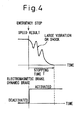
- Fig. 4 is a view showing the speed reduction characteristics of a conventional servo motor at the time of an emergency stop, as a relation between the rotation and time, together with the timing for activating a brake.
- the stopping time T can be reduced by activating both a dynamic brake and an electromagnetic brake at the time of an emergency stop, it has a problem that a decelerating torque immediately after the emergency stop becomes so large that vibration or shock may be induced during speed reduction.
- the vibration or shock thus induced corresponds to a disturbance in the curve of the speed reduction characteristics.
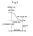
- Fig. 5 is a view showing an example of a speed reduction process of a servo motor in which, in order to overcome above-described problem, speed control is used in place of dynamic braking.
- Fig. 5 shows a case where speed reduction by means of speed control is employed at the time of an emergency stop, and an electromagnetic brake is activated after the rotation of the servo motor is stopped.
- the stopping time T of the servo motor is longer.
- smooth speed reduction characteristics are obtained only for the case of an emergency stop of a servo motor under a low load (low speed) conditions.
- the speed reduction characteristics are disturbed, as shown in Fig. 6.
- Fig. 6 is a view showing the torque characteristics and the speed reduction characteristics of a motor together with the timing for activating the electromagnetic brake.
- a wave-like disturbance in the curve of the speed reduction characteristics are caused by the inadequate torque of the servo motor.
- a wave-like disturbance in the curve of the speed reduction characteristics corresponds to a flat portion of the torque characteristics of the servo motor. That is, the decelerating torque required for speed reduction of the servo motor by means of speed control reaches the maximum allowable torque that is intrinsic to the individual servo motor (saturation of the decelerating torque), and thereby it become maybe difficult to accurately control the servo motor.
- the dashed line shows the speed command
- the solid line shows the resulting actual speed. It can be seen that the resulting speed shows a disturbance and the stopping time is longer.
- the present invention provides a servo motor stop controlling method for stopping the rotation of a servo motor provided with a brake, which comprises activating the brake, during speed reduction of the servo motor, by means of a speed control.
- a servo motor controller comprising a motor control section for controlling a servo motor provided with a brake, the motor control section comprising: a speed command portion for outputting a speed command to stop a rotation of the servo motor, and a brake switching portion for outputting a switch command for a braking circuit to switch the brake, wherein the brake is activated by the brake switching portion during speed reduction of the servo motor by the speed command portion, and the rotation of the servo motor is stopped.
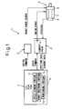
- FIG. 1 is a view showing the construction of a servo motor controller according to the present invention.
- a servo motor controller 1 is a controller for controlling a servo motor 2 for rotationally driving a joint portion of an unshown multi-joint type industrial robot, including a servo amplifier 3 for supplying a controlled current to the servo motor 2, a motor control section 4 electrically interconnected to the servo motor 2 via the servo amplifier 3, and a braking circuit 5 controlled by the motor control section 4 for ON/OFF switching of an electromagnetic brake (brake) 9.
- a servo amplifier 3 for supplying a controlled current to the servo motor 2
- a motor control section 4 electrically interconnected to the servo motor 2 via the servo amplifier 3
- a braking circuit 5 controlled by the motor control section 4 for ON/OFF switching of an electromagnetic brake (brake) 9.
- the servo motor 2 comprises a motor main body 7, an encoder 8 as a position detector for detecting the position information of the motor, and an electromagnetic brake 9 which functions as a frictional brake and a holding brake.
- the joint portion as a movable part is adapted to be driven by the servo motor 2 via an unshown speed reduction gear to increase output torque by reducing the rotation of the servo motor.
- the electromagnetic brake is mainly activated after the rotation of the servo motor 2 is stopped and functions as a so-called holding brake. In the present invention, it is also used to function as a frictional brake during speed reduction of the servo motor 2. It is assumed that decelerating torque of the brake when used as a frictional brake is equal to or smaller than the maximum allowable torque of the motor.
- the servo motor 2 of the present embodiment is described as applied to an industrial robot, it can also be applied to a horizontal axis displacing apparatus using a linear motor, a positioning apparatus using a servo motor and reduction gear, or to driving of feed axis, comprising a ball screw and a nut, of a machine tool.
- the servo amplifier 2 is a controller for accelerating, decelerating and stopping the servo motor 2 based on a speed command from the motor control section 4.
- the speed command "0" is used, for example, to control the servo motor 2 in a speed reduction control.
- the motor control section 4 comprises an unshown controller, an unshown shared memory, and a digital servo-circuit 6.
- a position command, etc. from the controller is transmitted via the shared memory to the digital servo-circuit 6.
- an error signal from the digital servo-circuit 6 is transmitted via the shared memory to the controller.
- transmission and reception are permitted in both direction via the shared memory between the controller and the digital servo-circuit 6.
- the digital servo-circuit 6 comprises an I/O circuit having electronic parts such as a CPU, ROM and RAM mounted thereon, of which, together with a control program, the speed command portion 11, the brake switching portion 12, and the monitoring portion 13 are composed.
- Position data from the encoder 8 are inputted to CPU, and speed data of the servo motor 2 are obtained by differentiating the position data.
- the value of motor current is also inputted from the servo amplifier 3 to CPU, and torque data for the motor 2 are obtained based on this current value.
- the speed command portion 11 constitutes a speed feedback circuit, and calculates the speed command value to be instructed to the motor 2 based on a position data, a speed data, and a torque data, and thus controls the servo motor 2 via the servo amplifier 3.
- the maximum allowable current is defined, by software, as the current supplied to the servo motor 2.
- the program has the function of clamping the motor current so as not to exceed the maximum allowable current. When this function is operated, it is determined that the torque has saturated.
- the speed command is "0"
- the torque command (current command) calculated by a feedback process is such that the servo motor 2 is driven in the reverse direction.
- the speed of the servo motor 2 is reduced by a specified decelerating torque, and the servo motor is stopped.
- the torque command value (the decelerating torque) is kept to the maximum allowable torque.
- the electromagnetic brake 9 is activated during a period when the torque command value (the braking torque) is kept to the maximum allowable torque (Fig. 2), so that the torque is decreased, during speed reduction, to prevent vibration or shock from being produced.
- the electromagnetic brake 9 can be switched between an activated state and an deactivated state of the electromagnetic brake 9 by switching the braking circuit ON or OFF with the brake switching portion 12 based on the torque command value that is being monitored by the monitoring portion 13.
- the above-mentioned monitoring portion 13 is means for monitoring whether or not the torque command value during speed reduction of the servo motor 2 exceeds a set value that has been, in advance, set equal to or lower than the maximum allowable torque of the servo motor.
- the set value that has been set in the motor controller portion is based on the maximum allowable torque of the motor. By selecting a set value that is smaller than the maximum allowable torque, it is possible to enable the brake in an early stage. This value is adjusted and determined so as to reduce a stopping distance and to stabilize a deceleration control.
- the above-mentioned brake switching portion 12 is means for outputting a switching command for the braking circuit 5 to switch the electromagnetic brake 9.
- Examples of the braking circuit include an electric circuit having a transistor and a relay, etc.
- the servo motor stop controller 1 performs stop control when an emergency stop instruction is inputted at step S1. If the rotation of the servo motor 2 at the time of the emergency stop instruction is low, that is, if the servo motor 2 is rotating at a low speed, the decelerating torque of the servo motor is not saturated by the stop control at step S2, and the servo motor can be stopped in a short time without producing vibration or shock even if the electromagnetic brake remains disabled. By activating the electromagnetic brake after the stop of the rotation, vibration or shock at the time of stopping can be eliminated, and the servo motor can be held in a stopped state.
- step S5 it is determined whether or not the stopping of the servo motor has been completed. If it is determined that the stopping has been completed, motor power is shut off at step S6, with the electromagnetic brake 9 remaining enabled.
- the electromagnetic brake 9 by activating the electromagnetic brake 9 during speed reduction of the servo motor 2, it is possible to use deceleration with speed control and braking by the electromagnetic brake 9 in combination to thereby increase the braking force on the servo motor and stop the servo motor within the maximum allowable torque of the servo motor 2. Therefore, in an emergency stop, the servo motor can be stopped in short time without producing vibration or shock.
- This embodiment of the present invention can be implemented in many ways. For example, in place of the monitoring portion for monitoring the decelerating torque during speed reduction of the servo motor 2, a monitoring portion for monitoring an error between the speed command value instructed by the speed command portion and the actual rotation of the servo motor 2, or a monitoring portion for monitoring an error between the position command value obtained by integrating the speed command value instructed by the speed command portion and the actual position of the servo motor 2, may be employed.
Landscapes
- Engineering & Computer Science (AREA)
- Power Engineering (AREA)
- Stopping Of Electric Motors (AREA)
- Control Of Electric Motors In General (AREA)
- Numerical Control (AREA)
Abstract
Description
- The present application is based on, and claims priority from,
Japanese Application Number 2005-295053, filed October 7, 2005 - The present invention applies generally to a system using a servo motor, such as an industrial robot, a machine tool, a positioning device, etc. More particularly, the present invention relates to a servo motor stop controlling method and a servo motor controller in which the rotation of a servo motor provided with a brake is stopped by means of speed control.
- Conventionally, in various systems comprising a servo motor, in order to stop the rotation of a servo motor safely and in as short a time period as possible at the time of an emergency stop, a dynamic brake utilizing regenerative energy of the servo motor and an electromagnetic brake are used in combination for reducing the speed of, and stopping, the servo motor, and after the servo motor has been stopped, the electromagnetic brake is used to hold the movable part in a stopped state. Fig. 4 is a view showing the speed reduction characteristics of a conventional servo motor at the time of an emergency stop, as a relation between the rotation and time, together with the timing for activating a brake.
- As shown in Fig. 4, although the stopping time T can be reduced by activating both a dynamic brake and an electromagnetic brake at the time of an emergency stop, it has a problem that a decelerating torque immediately after the emergency stop becomes so large that vibration or shock may be induced during speed reduction. The vibration or shock thus induced corresponds to a disturbance in the curve of the speed reduction characteristics.
- Fig. 5 is a view showing an example of a speed reduction process of a servo motor in which, in order to overcome above-described problem, speed control is used in place of dynamic braking. Fig. 5 shows a case where speed reduction by means of speed control is employed at the time of an emergency stop, and an electromagnetic brake is activated after the rotation of the servo motor is stopped. As can be seen from Fig. 5, although vibration or shock is not produced in this case, and the curve exhibiting the speed reduction characteristics is smooth, the stopping time T of the servo motor is longer. Moreover, smooth speed reduction characteristics are obtained only for the case of an emergency stop of a servo motor under a low load (low speed) conditions. In the case of an emergency stop of a servo motor under a high speed or load conditions, the speed reduction characteristics are disturbed, as shown in Fig. 6.
- Fig. 6 is a view showing the torque characteristics and the speed reduction characteristics of a motor together with the timing for activating the electromagnetic brake. A wave-like disturbance in the curve of the speed reduction characteristics are caused by the inadequate torque of the servo motor. In other words, a wave-like disturbance in the curve of the speed reduction characteristics corresponds to a flat portion of the torque characteristics of the servo motor. That is, the decelerating torque required for speed reduction of the servo motor by means of speed control reaches the maximum allowable torque that is intrinsic to the individual servo motor (saturation of the decelerating torque), and thereby it become maybe difficult to accurately control the servo motor. In Fig. 6, the dashed line shows the speed command, and the solid line shows the resulting actual speed. It can be seen that the resulting speed shows a disturbance and the stopping time is longer.
- As has been described above, it is possible to stop a servo motor smoothly by speed control of the servo motor. However, there is a problem that, when a servo motor is quickly stopped from the state of high speed or high load of the servo motor, the decelerating torque saturates and the servo motor may become difficult to accurately control the servo motor and give rise to vibration and delay in response to a control command. Thus, although, in an emergency stop from the state of low speed or low load, it is possible to stop the rotation of servo motor in a short time period by speed control, there is a problem that, in an emergency stop from the condition of nearly maximum speed or maximum load, the servo motor may be unable to provide adequate torque and thus may give rise to vibration or delay in the response to a control signal.
- It is an object of the present invention to solve the above-described problem and to provide a servo motor stop controlling method and a servo motor controller that is capable of stopping the rotation of a servo motor, in case of an emergency stop, in a shorter stop time with a reduced stopping distance.
- To accomplish the above objects, the present invention provides a servo motor stop controlling method for stopping the rotation of a servo motor provided with a brake, which comprises activating the brake, during speed reduction of the servo motor, by means of a speed control.
- According to the present invention, there is further provided a servo motor controller comprising a motor control section for controlling a servo motor provided with a brake, the motor control section comprising: a speed command portion for outputting a speed command to stop a rotation of the servo motor, and a brake switching portion for outputting a switch command for a braking circuit to switch the brake, wherein the brake is activated by the brake switching portion during speed reduction of the servo motor by the speed command portion, and the rotation of the servo motor is stopped.
- These and other objects and features of the present invention will become clearer from the following description of the preferred embodiments given with reference to the attached drawings, wherein:
- Fig. 1 is a view showing the construction of a servo motor controller according to an embodiment of the present invention;
- Fig. 2 is a view showing the torque characteristics and the speed reduction characteristics together with the timing of activating of the electromagnetic brake;
- Fig. 3 is a flow chart showing the process of a stop control by the servo motor controller;
- Fig. 4 is a view showing an example of the speed reduction characteristics of the motor together with the timing of activating of a dynamic brake and an electromagnetic brake in a conventional servo motor controller;
- Fig. 5 is a view showing another example of the speed reduction characteristics of the motor together with the timing of activating of an electromagnetic brake in a conventional servo motor controller; and
- Fig. 6 is a view showing the torque characteristics and the speed reduction characteristics of the motor together with the timing of activating of an electromagnetic brake in a conventional servo motor controller.
- Next, the present invention will be described, in detail, with reference to drawings showing specific examples of embodiments thereof. Fig. 1 is a view showing the construction of a servo motor controller according to the present invention.
- A servo motor controller 1 according to the present embodiment is a controller for controlling a servo motor 2 for rotationally driving a joint portion of an unshown multi-joint type industrial robot, including a
servo amplifier 3 for supplying a controlled current to the servo motor 2, a motor control section 4 electrically interconnected to the servo motor 2 via theservo amplifier 3, and abraking circuit 5 controlled by the motor control section 4 for ON/OFF switching of an electromagnetic brake (brake) 9. - The servo motor 2 comprises a motor
main body 7, anencoder 8 as a position detector for detecting the position information of the motor, and anelectromagnetic brake 9 which functions as a frictional brake and a holding brake. The joint portion as a movable part is adapted to be driven by the servo motor 2 via an unshown speed reduction gear to increase output torque by reducing the rotation of the servo motor. - The electromagnetic brake is mainly activated after the rotation of the servo motor 2 is stopped and functions as a so-called holding brake. In the present invention, it is also used to function as a frictional brake during speed reduction of the servo motor 2. It is assumed that decelerating torque of the brake when used as a frictional brake is equal to or smaller than the maximum allowable torque of the motor.
- Although the servo motor 2 of the present embodiment is described as applied to an industrial robot, it can also be applied to a horizontal axis displacing apparatus using a linear motor, a positioning apparatus using a servo motor and reduction gear, or to driving of feed axis, comprising a ball screw and a nut, of a machine tool.
- The servo amplifier 2 is a controller for accelerating, decelerating and stopping the servo motor 2 based on a speed command from the motor control section 4. When the servo motor is to be decelerated and stopped, the speed command "0" is used, for example, to control the servo motor 2 in a speed reduction control.
- The motor control section 4 comprises an unshown controller, an unshown shared memory, and a digital servo-
circuit 6. A position command, etc. from the controller is transmitted via the shared memory to the digital servo-circuit 6. Conversely, an error signal from the digital servo-circuit 6 is transmitted via the shared memory to the controller. Thus, transmission and reception are permitted in both direction via the shared memory between the controller and the digital servo-circuit 6. - The digital servo-
circuit 6 comprises an I/O circuit having electronic parts such as a CPU, ROM and RAM mounted thereon, of which, together with a control program, thespeed command portion 11, the brake switching portion 12, and themonitoring portion 13 are composed. Position data from theencoder 8 are inputted to CPU, and speed data of the servo motor 2 are obtained by differentiating the position data. The value of motor current is also inputted from theservo amplifier 3 to CPU, and torque data for the motor 2 are obtained based on this current value. - The
speed command portion 11 constitutes a speed feedback circuit, and calculates the speed command value to be instructed to the motor 2 based on a position data, a speed data, and a torque data, and thus controls the servo motor 2 via theservo amplifier 3. The maximum allowable current is defined, by software, as the current supplied to the servo motor 2. When the instructed motor current exceeds the maximum allowable current, the program has the function of clamping the motor current so as not to exceed the maximum allowable current. When this function is operated, it is determined that the torque has saturated. - For example, in the stop control of the servo motor 2, the speed command is "0", and as a result, the torque command (current command) calculated by a feedback process is such that the servo motor 2 is driven in the reverse direction. The speed of the servo motor 2 is reduced by a specified decelerating torque, and the servo motor is stopped. In the case of an emergency stop in which the servo motor 2 is stopped from the state of rotation under maximum load, the torque command value (the decelerating torque) is kept to the maximum allowable torque. In the present invention, the
electromagnetic brake 9 is activated during a period when the torque command value (the braking torque) is kept to the maximum allowable torque (Fig. 2), so that the torque is decreased, during speed reduction, to prevent vibration or shock from being produced. - The
electromagnetic brake 9 can be switched between an activated state and an deactivated state of theelectromagnetic brake 9 by switching the braking circuit ON or OFF with the brake switching portion 12 based on the torque command value that is being monitored by the monitoringportion 13. - The above-mentioned
monitoring portion 13 is means for monitoring whether or not the torque command value during speed reduction of the servo motor 2 exceeds a set value that has been, in advance, set equal to or lower than the maximum allowable torque of the servo motor. The set value that has been set in the motor controller portion is based on the maximum allowable torque of the motor. By selecting a set value that is smaller than the maximum allowable torque, it is possible to enable the brake in an early stage. This value is adjusted and determined so as to reduce a stopping distance and to stabilize a deceleration control. - The above-mentioned brake switching portion 12 is means for outputting a switching command for the
braking circuit 5 to switch theelectromagnetic brake 9. Examples of the braking circuit include an electric circuit having a transistor and a relay, etc. - Next, a processing flow of a servo motor stop controller at the time of an emergency stop will be described with reference to Fig. 3. The servo motor stop controller 1 performs stop control when an emergency stop instruction is inputted at step S1. If the rotation of the servo motor 2 at the time of the emergency stop instruction is low, that is, if the servo motor 2 is rotating at a low speed, the decelerating torque of the servo motor is not saturated by the stop control at step S2, and the servo motor can be stopped in a short time without producing vibration or shock even if the electromagnetic brake remains disabled. By activating the electromagnetic brake after the stop of the rotation, vibration or shock at the time of stopping can be eliminated, and the servo motor can be held in a stopped state.
- On the other hand, if the speed of the motor at the time of the emergency stop instruction is high, that is, if the servo motor 2 is rotating at a high speed, saturation of the servo motor 2 is detected at step S3 (Fig. 2), and at step S4, when the decelerating torque is saturated, the
electromagnetic brake 9 is activated, and the saturated state of the decelerating torque discontinue thereby. At step S5, it is determined whether or not the stopping of the servo motor has been completed. If it is determined that the stopping has been completed, motor power is shut off at step S6, with theelectromagnetic brake 9 remaining enabled. Thus, if the speed of the motor at the time of the emergency stop instruction is high, saturation of the decelerating torque can be avoided with the assistance of theelectromagnetic brake 9, and the servo motor can be stopped smoothly in a short time. - As has been described above, in accordance with the present embodiment, by activating the
electromagnetic brake 9 during speed reduction of the servo motor 2, it is possible to use deceleration with speed control and braking by theelectromagnetic brake 9 in combination to thereby increase the braking force on the servo motor and stop the servo motor within the maximum allowable torque of the servo motor 2. Therefore, in an emergency stop, the servo motor can be stopped in short time without producing vibration or shock. - This embodiment of the present invention can be implemented in many ways. For example, in place of the monitoring portion for monitoring the decelerating torque during speed reduction of the servo motor 2, a monitoring portion for monitoring an error between the speed command value instructed by the speed command portion and the actual rotation of the servo motor 2, or a monitoring portion for monitoring an error between the position command value obtained by integrating the speed command value instructed by the speed command portion and the actual position of the servo motor 2, may be employed.
- It is also possible to activate the electromagnetic brake during speed reduction of the servo motor 2, and to deactivate the electromagnetic brake after the load on the motor is reduced and the torque is decreased in order to stop the servo motor solely by deceleration with the speed control of the servo motor, and to enable the electromagnetic brake again after the servo motor has been stopped. In this manner, a control required for compensating excessive braking can be eliminated.
- While the invention has been described with reference to specific embodiments chosen for purpose of illustration, it should be apparent that numerous modifications could be made thereto by those skilled in the art without departing from the basic concept and scope of the invention.
Claims (9)
- A servo motor stop controlling method for stopping a rotation of a servo motor (2) provided with a brake (9),
characterized in that the servo motor stop controlling method comprises activating the brake (9), during speed reduction of the servo motor (2), by means of a speed control,
whereby a rotation of the servo motor (2) is stopped. - A servo motor stop controlling method according to claim 1,
characterized in that the rotation of the servo motor (2) is stopped within maximum allowable torque of the servo motor (2). - A servo motor stop controlling method according to claim 2,
characterized in that a decelerating torque of the servo motor (2) is compared with a set value that has been set equal to or lower than maximum allowable torque of the servo motor (2) in the motor control section (4), and the brake (9) is activated when the decelerating torque exceeds the set value. - A servo motor controller comprising a motor control section (4) for controlling a servo motor (2) provided with a brake (9), the motor control section (4) including a speed command portion (11) for outputting a speed command to stop a rotation of the servo motor (2),
characterized in that the motor control section (4) includes a brake switching portion (12) for outputting a switch command for a braking circuit (5) to switch the brake (9),
wherein the brake (9) is activated by the brake switching portion (12) during speed reduction of the servo motor (2) by the speed command portion (12), and the rotation of the servo motor is stopped. - A servo motor controller according to claim 4,
wherein the rotation of the servo motor (2) is stopped within a maximum allowable torque of the servo motor (2). - A servo motor controller according to claim 5,
wherein the motor control section (4) further comprises a monitoring portion (13) for monitoring whether or not a decelerating torque of the servo motor (2) during speed reduction exceeds a set value that has been set equal to or lower than a maximum allowable torque of the servo motor (2) in the motor control section (4), the brake is activated by the brake switching portion (12) when it is detected by the monitoring portion (13) that the decelerating torque exceeds the set value. - A servo motor controller according to claim 5,
wherein the motor control section (4) further comprises a monitoring portion for monitoring an error between a speed command value instructed by the speed command portion (11) and a actual speed of the servo motor (2) and the brake (9) is activated by the brake switching portion (12) when the error is found to be larger than a set value in the motor control section (4). - A servo motor controller according to claim 5,
wherein the motor control section (4) further comprises a monitoring portion for monitoring an error between a position command value obtained by integrating a speed command value instructed by the speed command portion (11) and an actual position of the servo motor (2), the brake (9) is activated by the brake switching portion (12) when the error is found to be larger than a set value in the motor control section (4). - A servo motor controller according to claim 6,
wherein, after the breaking torque is decreased to less than the set value by a braking assistance of the brake (9), the brake (9) is deactivated by the brake switching portion (12) and the servo motor (2) is stopped only by a deceleration of the speed command portion (11).
Applications Claiming Priority (1)
| Application Number | Priority Date | Filing Date | Title |
|---|---|---|---|
| JP2005295053A JP4053557B2 (en) | 2005-10-07 | 2005-10-07 | Servo motor stop control method and servo motor control apparatus |
Publications (2)
| Publication Number | Publication Date |
|---|---|
| EP1775829A2 true EP1775829A2 (en) | 2007-04-18 |
| EP1775829A3 EP1775829A3 (en) | 2014-02-19 |
Family
ID=37726694
Family Applications (1)
| Application Number | Title | Priority Date | Filing Date |
|---|---|---|---|
| EP06020768.5A Withdrawn EP1775829A3 (en) | 2005-10-07 | 2006-10-02 | Servo motor stop controlling method and servo motor controller |
Country Status (4)
| Country | Link |
|---|---|
| US (1) | US20070096670A1 (en) |
| EP (1) | EP1775829A3 (en) |
| JP (1) | JP4053557B2 (en) |
| CN (1) | CN1945471A (en) |
Cited By (3)
| Publication number | Priority date | Publication date | Assignee | Title |
|---|---|---|---|---|
| US20120073354A1 (en) * | 2010-09-23 | 2012-03-29 | Honeywell International Inc. | Apparatus and methods for automatically testing a servo gauge in an inventory management system |
| EP2228204B1 (en) | 2008-01-08 | 2015-04-08 | Aida Engineering, Ltd. | Electric servo-press and control method for electric servo press |
| EP3076540A2 (en) | 2015-03-30 | 2016-10-05 | Tata Elxsi Limited | System and method for the automatic validation of motor control firmware of an embedded system |
Families Citing this family (29)
| Publication number | Priority date | Publication date | Assignee | Title |
|---|---|---|---|---|
| JP4468047B2 (en) * | 2004-04-02 | 2010-05-26 | コベルコ建機株式会社 | Emergency turning brake device for work machines |
| JP4270012B2 (en) * | 2004-04-07 | 2009-05-27 | コベルコ建機株式会社 | Swivel work machine |
| US20090053031A1 (en) * | 2007-08-23 | 2009-02-26 | Humble Erik L | Underlayment stickering stacker control |
| JP2010099799A (en) * | 2008-10-24 | 2010-05-06 | Brother Ind Ltd | Machine tool |
| JP5458768B2 (en) * | 2009-09-17 | 2014-04-02 | 株式会社デンソーウェーブ | Robot control apparatus and control method |
| JP5351752B2 (en) * | 2009-12-28 | 2013-11-27 | 株式会社マキタ | Electric tool |
| JP5778891B2 (en) * | 2010-01-27 | 2015-09-16 | 川崎重工業株式会社 | Robot controller |
| CN101844317B (en) * | 2010-03-25 | 2011-12-14 | 合肥工业大学 | Device and method for correcting transmission error of precise numerical control machine closed loop servo system |
| SI2737621T1 (en) * | 2011-07-26 | 2022-10-28 | Moog Inc. | Electric motor clamping system |
| JP6051021B2 (en) * | 2012-08-09 | 2016-12-21 | 日本電産サンキョー株式会社 | Industrial robot and control method for industrial robot |
| KR101688360B1 (en) * | 2013-03-14 | 2016-12-20 | 미쓰비시덴키 가부시키가이샤 | Servo control device |
| JP5746308B2 (en) * | 2013-11-26 | 2015-07-08 | ファナック株式会社 | Servo control device with a function to reduce the brake fall amount |
| CN107072724B (en) | 2014-10-27 | 2019-10-25 | 直观外科手术操作公司 | System and method for device interference compensation |
| KR102617042B1 (en) | 2014-10-27 | 2023-12-27 | 인튜어티브 서지컬 오퍼레이션즈 인코포레이티드 | System and method for registering to a surgical table |
| CN111166476B (en) | 2014-10-27 | 2023-05-02 | 直观外科手术操作公司 | Medical devices with active brake release controls |
| WO2016069660A1 (en) | 2014-10-27 | 2016-05-06 | Intuitive Surgical Operations, Inc. | System and method for monitoring control points during reactive motion |
| WO2016069648A1 (en) | 2014-10-27 | 2016-05-06 | Intuitive Surgical Operations, Inc. | System and method for integrated surgical table |
| CN107072746B (en) | 2014-10-27 | 2020-06-09 | 直观外科手术操作公司 | System and method for integrating surgical table icons |
| EP3212151B1 (en) | 2014-10-27 | 2020-07-29 | Intuitive Surgical Operations, Inc. | System for integrated surgical table motion |
| JP6661910B2 (en) * | 2015-07-27 | 2020-03-11 | セイコーエプソン株式会社 | Control method |
| JP6527095B2 (en) * | 2016-03-25 | 2019-06-05 | ファナック株式会社 | Motor and mechanism having brake torque increasing / decreasing function |
| JP6643968B2 (en) * | 2016-10-20 | 2020-02-12 | 株式会社ミツバ | SR motor control system and SR motor control method |
| JP6445079B2 (en) * | 2017-04-26 | 2018-12-26 | ファナック株式会社 | Servo motor control device and servo motor control system |
| DE102017005604A1 (en) | 2017-06-12 | 2018-12-13 | Kuka Deutschland Gmbh | Monitoring a robot |
| CN110134066B (en) * | 2018-02-09 | 2022-06-28 | 西门子公司 | Method, device, system and storage medium for compensating rotation speed of lathe workpiece |
| CN110181507B (en) * | 2019-05-07 | 2020-11-20 | 成都卡诺普自动化控制技术有限公司 | Emergency stop control method and system for robot |
| JP7269097B2 (en) * | 2019-05-30 | 2023-05-08 | ファナック株式会社 | rotary axis controller |
| KR102934887B1 (en) * | 2020-12-24 | 2026-03-10 | 현대자동차주식회사 | Apparatus for controlling pressure vessel and method thereof |
| CN113098333B (en) * | 2021-04-01 | 2022-03-29 | 东风汽车集团股份有限公司 | Control method of air conditioner servo motor |
Family Cites Families (10)
| Publication number | Priority date | Publication date | Assignee | Title |
|---|---|---|---|---|
| US4267914A (en) * | 1979-04-26 | 1981-05-19 | Black & Decker Inc. | Anti-kickback power tool control |
| JPS5733174A (en) * | 1980-08-01 | 1982-02-23 | Hitachi Ltd | Controller for elevator |
| JPS6377726A (en) * | 1986-09-19 | 1988-04-07 | Fanuc Ltd | Motor-driven direct pressure-type clamping control with 2 motors |
| JP2506214B2 (en) * | 1990-01-17 | 1996-06-12 | オークマ株式会社 | Numerically controlled machine tool collision detection device |
| DE4413047C2 (en) * | 1994-04-15 | 1996-04-18 | Roland Man Druckmasch | Method and device for brake monitoring the DC motor of a printing press |
| US5828195A (en) * | 1996-08-29 | 1998-10-27 | Universal Instruments Corporation | Method and apparatus for electronic braking of an electric motor having no permanent magnets |
| US6536536B1 (en) * | 1999-04-29 | 2003-03-25 | Stephen F. Gass | Power tools |
| US8061245B2 (en) * | 2000-09-29 | 2011-11-22 | Sd3, Llc | Safety methods for use in power equipment |
| KR100674516B1 (en) * | 2002-05-09 | 2007-01-26 | 코벨코 겐키 가부시키가이샤 | Rotation control device of working machine |
| JP4136949B2 (en) * | 2004-01-16 | 2008-08-20 | 株式会社小松製作所 | Runaway monitoring device for electric servo press |
-
2005
- 2005-10-07 JP JP2005295053A patent/JP4053557B2/en not_active Expired - Fee Related
-
2006
- 2006-09-29 CN CNA2006101599970A patent/CN1945471A/en active Pending
- 2006-10-02 EP EP06020768.5A patent/EP1775829A3/en not_active Withdrawn
- 2006-10-05 US US11/539,134 patent/US20070096670A1/en not_active Abandoned
Cited By (4)
| Publication number | Priority date | Publication date | Assignee | Title |
|---|---|---|---|---|
| EP2228204B1 (en) | 2008-01-08 | 2015-04-08 | Aida Engineering, Ltd. | Electric servo-press and control method for electric servo press |
| US20120073354A1 (en) * | 2010-09-23 | 2012-03-29 | Honeywell International Inc. | Apparatus and methods for automatically testing a servo gauge in an inventory management system |
| US8997549B2 (en) * | 2010-09-23 | 2015-04-07 | Honeywell International Inc. | Apparatus and methods for automatically testing a servo gauge in an inventory management system |
| EP3076540A2 (en) | 2015-03-30 | 2016-10-05 | Tata Elxsi Limited | System and method for the automatic validation of motor control firmware of an embedded system |
Also Published As
| Publication number | Publication date |
|---|---|
| JP2007104869A (en) | 2007-04-19 |
| JP4053557B2 (en) | 2008-02-27 |
| US20070096670A1 (en) | 2007-05-03 |
| EP1775829A3 (en) | 2014-02-19 |
| CN1945471A (en) | 2007-04-11 |
Similar Documents
| Publication | Publication Date | Title |
|---|---|---|
| US20070096670A1 (en) | Servo motor stop controlling method and servo motor controller | |
| CN101261510B (en) | Numerical controller with abnormal motor deceleration stop control means | |
| EP2372478B1 (en) | Motor driving system and motor controller | |
| US5142210A (en) | Abnormal state detecting apparatus of a machine tool | |
| US9334911B2 (en) | Servo controller having function for reducing dropping when braking | |
| US6741057B2 (en) | Servo controller for preventing downward displacement in gravitating axis | |
| EP0108384A1 (en) | Safety maintaining method and apparatus for automatic machines | |
| JPH09179623A (en) | Method and device for controlling mechanical device by numerical control | |
| JP2011118709A (en) | Abnormality monitor for mobile body driving control system | |
| US6970761B2 (en) | Method for actuating a holding brake | |
| US11086300B2 (en) | Control method, control device and program recording medium | |
| JP2024147131A (en) | Motor Control Device | |
| JP2003009563A (en) | Servo motor controller | |
| JP5309812B2 (en) | Motor control device and motor control method | |
| JP2019170056A (en) | Motor control device and method for controlling motor control device | |
| JP2024147130A (en) | Motor Control Device | |
| JPH11347874A (en) | Stop control device for machine tool | |
| JPH05250022A (en) | Control system for motor | |
| JPH02189601A (en) | Drive control device | |
| JP2006304537A (en) | Electromagnetic brake control device for motor | |
| JP2006352945A (en) | Abnormal load detection method for movable units | |
| JPH01197812A (en) | Fixed position stop controller | |
| JPH06242813A (en) | Machining controller for robot | |
| JP3348423B2 (en) | How to determine the load direction of the robot arm | |
| JP2008211953A (en) | Servo controller for motor |
Legal Events
| Date | Code | Title | Description |
|---|---|---|---|
| PUAI | Public reference made under article 153(3) epc to a published international application that has entered the european phase |
Free format text: ORIGINAL CODE: 0009012 |
|
| AK | Designated contracting states |
Kind code of ref document: A2 Designated state(s): AT BE BG CH CY CZ DE DK EE ES FI FR GB GR HU IE IS IT LI LT LU LV MC NL PL PT RO SE SI SK TR |
|
| AX | Request for extension of the european patent |
Extension state: AL BA HR MK YU |
|
| RIN1 | Information on inventor provided before grant (corrected) |
Inventor name: HAMADA, TOSHIHIKOFANUC DAI3VIRAKARAMATSU Inventor name: TANABE, YOSHIKIYOROOM 101 Inventor name: HASHIMOTO, YOSHIKI |
|
| RAP1 | Party data changed (applicant data changed or rights of an application transferred) |
Owner name: FANUC CORPORATION |
|
| PUAL | Search report despatched |
Free format text: ORIGINAL CODE: 0009013 |
|
| AK | Designated contracting states |
Kind code of ref document: A3 Designated state(s): AT BE BG CH CY CZ DE DK EE ES FI FR GB GR HU IE IS IT LI LT LU LV MC NL PL PT RO SE SI SK TR |
|
| AX | Request for extension of the european patent |
Extension state: AL BA HR MK RS |
|
| RIC1 | Information provided on ipc code assigned before grant |
Ipc: H02P 3/26 20060101ALI20140116BHEP Ipc: H02P 3/04 20060101AFI20140116BHEP Ipc: H02P 3/16 20060101ALI20140116BHEP |
|
| AKX | Designation fees paid |
Designated state(s): DE |
|
| STAA | Information on the status of an ep patent application or granted ep patent |
Free format text: STATUS: THE APPLICATION IS DEEMED TO BE WITHDRAWN |
|
| 18D | Application deemed to be withdrawn |
Effective date: 20140820 |