EP1775601A1 - System and method for forming 3-dimensional images using multiple sectional plane images - Google Patents
System and method for forming 3-dimensional images using multiple sectional plane images Download PDFInfo
- Publication number
- EP1775601A1 EP1775601A1 EP06021475A EP06021475A EP1775601A1 EP 1775601 A1 EP1775601 A1 EP 1775601A1 EP 06021475 A EP06021475 A EP 06021475A EP 06021475 A EP06021475 A EP 06021475A EP 1775601 A1 EP1775601 A1 EP 1775601A1
- Authority
- EP
- European Patent Office
- Prior art keywords
- image
- sectional plane
- dimensional
- forming
- region
- Prior art date
- Legal status (The legal status is an assumption and is not a legal conclusion. Google has not performed a legal analysis and makes no representation as to the accuracy of the status listed.)
- Granted
Links
Images



Classifications
-
- A—HUMAN NECESSITIES
- A61—MEDICAL OR VETERINARY SCIENCE; HYGIENE
- A61B—DIAGNOSIS; SURGERY; IDENTIFICATION
- A61B8/00—Diagnosis using ultrasonic, sonic or infrasonic waves
-
- A—HUMAN NECESSITIES
- A61—MEDICAL OR VETERINARY SCIENCE; HYGIENE
- A61B—DIAGNOSIS; SURGERY; IDENTIFICATION
- A61B8/00—Diagnosis using ultrasonic, sonic or infrasonic waves
- A61B8/48—Diagnostic techniques
- A61B8/483—Diagnostic techniques involving the acquisition of a 3D volume of data
-
- G—PHYSICS
- G01—MEASURING; TESTING
- G01S—RADIO DIRECTION-FINDING; RADIO NAVIGATION; DETERMINING DISTANCE OR VELOCITY BY USE OF RADIO WAVES; LOCATING OR PRESENCE-DETECTING BY USE OF THE REFLECTION OR RERADIATION OF RADIO WAVES; ANALOGOUS ARRANGEMENTS USING OTHER WAVES
- G01S15/00—Systems using the reflection or reradiation of acoustic waves, e.g. sonar systems
- G01S15/88—Sonar systems specially adapted for specific applications
- G01S15/89—Sonar systems specially adapted for specific applications for mapping or imaging
- G01S15/8906—Short-range imaging systems; Acoustic microscope systems using pulse-echo techniques
- G01S15/8993—Three dimensional imaging systems
-
- G—PHYSICS
- G01—MEASURING; TESTING
- G01S—RADIO DIRECTION-FINDING; RADIO NAVIGATION; DETERMINING DISTANCE OR VELOCITY BY USE OF RADIO WAVES; LOCATING OR PRESENCE-DETECTING BY USE OF THE REFLECTION OR RERADIATION OF RADIO WAVES; ANALOGOUS ARRANGEMENTS USING OTHER WAVES
- G01S7/00—Details of systems according to groups G01S13/00, G01S15/00, G01S17/00
- G01S7/52—Details of systems according to groups G01S13/00, G01S15/00, G01S17/00 of systems according to group G01S15/00
- G01S7/52017—Details of systems according to groups G01S13/00, G01S15/00, G01S17/00 of systems according to group G01S15/00 particularly adapted to short-range imaging
- G01S7/52053—Display arrangements
- G01S7/52057—Cathode ray tube displays
- G01S7/52074—Composite displays, e.g. split-screen displays; Combination of multiple images or of images and alphanumeric tabular information
Definitions
- the present invention generally relates to image forming systems, and more particularly to a system and a method for forming a 3-dimensional image by using multiple sectional plane images of a target object.
- An ultrasound diagnostic system has become an important and popular diagnostic tool since it has a wide range of applications. Specifically, due to its non-invasive and non-destructive nature, the ultrasound diagnostic system has been extensively used in the medical profession. Modem high-performance ultrasound diagnostic systems and techniques are commonly used to produce two or three-dimensional diagnostic images of internal features of an object (e.g., human organs).
- an object e.g., human organs
- the ultrasound diagnostic system generally uses a wide bandwidth transducer to transmit and receive ultrasound signals.
- the ultrasound diagnostic system forms images of human internal tissues by electrically exciting an acoustic transducer element or an array of acoustic transducer elements to generate ultrasound signals that travel into the body.
- the ultrasound signals produce ultrasound echo signals since they are reflected from body tissues, which appear as discontinuities to the propagating ultrasound signals.
- Various ultrasound echo signals return to the transducer element and are converted into electrical signals, which are amplified and processed to produce ultrasound data for an image of the tissues.
- the ultrasound diagnostic system is very important in the medical field since it provides physicians with real-time and high-resolution images of human internal features without the need for invasive observation techniques such as surgery.
- the conventional ultrasound diagnostic system acquires 3-dimensional ultrasound data from ultrasound echo signals and forms a 3-dimensional ultrasound image based on the acquired 3-dimensional ultrasound data.
- the entire 3-dimensional ultrasound data are used to form one 3-dimensional ultrasound image, even if the desired portions are different from each other, according to the users' or specific diagnostic purposes. Therefore, such ultrasound diagnostic system is highly inconvenient since the user is required to find a desirable portion in the 3-dimensional ultrasound image.
- the conventional ultrasound diagnostic system uses the entire 3-dimensional ultrasound data to form the 3-dimensional ultrasound image, it takes a very long time to form the 3-dimensional ultrasound image.
- the present invention provides a system and a method for setting a region of interest on multiple sectional plane images, extracting data included in the region of interest from 3-dimensional ultrasound image data and performing image rendering for the extracted data, thereby forming a desirable 3-dimensional ultrasound image.
- a system for forming 3-dimensional images including: an image data forming unit for forming 3-dimensional volume data based on image signals; an image forming unit for forming multiple sectional plane images sliced along a predetermined direction in a 3-dimensional image, the image forming unit being configured to form at least one 3-dimensional image with partial 3-dimensional volume data selected by using the multiple sectional plane images from the 3-dimensional volume data; and a displaying unit for displaying the multiple sectional plane images and the 3-dimensional image.
- a method of forming 3-dimensional images including the steps of: a) forming 3-dimensional volume data based on image signals; b) forming multiple sectional plane images sliced along a predetermined direction in a 3-dimensional image; c) selecting one of the multiple section plane images; d) forming a reference sectional plane image orthogonal to the selected sectional plane image; e) setting a predetermined region on the reference sectional plane image; l) extracting data included in the predetermined region from the 3-dimensional volume data; g) performing image rendering for the extracted data; and h) forming at least one 3-dimensional image.
- Fig. 1 is a block diagram showing an ultrasound diagnostic system 100, which is constructed in accordance with the present invention.
- the ultrasound diagnostic system 100 of the present invention includes a probe I 10, a beam former 120, an image signal processor 130, a scan converter 140, an image processor 150, a display unit 160 and an input unit 170.
- the ultrasound diagnostic system 100 further includes a memory (not shown) for storing 2-dimensional ultrasound image data and 3-dimensional ultrasound image data. Also, the image signal processor 130 and the image processor 150 may be provided as one processor.
- the probe 110 includes a 1-dimensional or a 2-dimensional array transducer 112.
- the transmit signals which are appropriately delayed in the beam former 120 to form an ultrasound beam, are transmitted to the array transducer 112.
- the focused ultrasound beam which is produced in response to the transmit signals, is transmitted along a scan line of a target object (not shown).
- the probe 110 receives ultrasound echo signals reflected from the target object and converts the ultrasound echo signals into electrical signals (hereinafter referred to as receive signals).
- receive signals are transmitted to the beam former 120.
- the beam former 120 provides delays of transmit signals to be transmitted to the array transducer 112 included in the probe 110 such that the ultrasound signals outputted from the array transducer 112 arc focused on a focal point. Further, the beam former 120 focuses the receive signals, which are received from the array transducer 112 included in the probe 110, in consideration of the delays with which the echo signals are arrived at each transducer. It then outputs a focused receive beam representing an energy level of the ultrasound echo signal reflected from the focal point.
- the image signal processor 130 (e.g., a digital signal processor (DSP)) performs envelop detection for detecting intensities of the focused receive signals to form ultrasound image data. That is, the image signal processor 130 forms 3-dimensional ultrasound image data based on the receive focused signals acquired from each focal point and position information of a plurality of focal points on each scan line.
- the 3-dimensional ultrasound image data incl ude coordinates information of each focal point, angle information of each scan line and intensity information of the echo signals received at each focal point.
- the scan converter 140 scan-converts the 3-dimensional ultrasound image data to a data format capable of being displayed on a screen of the display unit 160.
- the image processor 150 forms multiple sectional plane images in response to a plane selecting instruction, which is inputted by a user to determine an image slicing direction of sectional plane images. Also, the image processor 150 forms a partial 3-dimensional ultrasound image corresponding to a predetermined region of the 3-dimensional ultrasound image data in response to a region setting instruction inputted from the user.
- the 3-dimensional ultrasound image is displayed on the display unit 160.
- the input unit 170 receives user's selections to transmit the plane selecting instruction and the region setting instruction to the image processor 150.
- the input unit 170 may be a mouse, a track ball, a keyboard, a touch pad or the like.
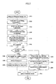
- Fig. 2 is a flowchart that shows the operation of the image processor constructed in accordance with the present invention.
- the image processor 150 forms multiple sectional plane images in a predetermined image slicing direction, which is determined in response to the plane selecting instruction at step S120.
- One of the multiple sectional plane images is selected at step S130.
- the selected sectional plane image may contain images, which are desirable for diagnosis.
- a reference sectional plane image, which is orthogonal to the selected sectional plane image, is formed at step S140.
- the reference sectional plane image is used for setting a region representing the width of a partial 3-dimensional ultrasound image (hereinafter referred to as a 3-dimensional region) in the 3-diniensional ultrasound image data.
- the partial 3-dimensional ultrasound image contains images for diagnosis.
- a B sectional plane image or a C sectional plane image becomes a reference sectional plane image.
- the selected sectional plane image is the B sectional plane image
- the C sectional plane image or the A sectional plane image becomes a reference sectional plane image.
- the selected sectional plane image is the C sectional plane image
- the A sectional plane image or the B sectional plane image becomes a reference sectional plane image.
- the multiple sectional plane images are displayed on a multiple sectional plane image displaying part 210, whereas the reference sectional plane image is displayed on a reference sectional plane image displaying part 220, as shown in Fig. 4 at step S 150.
- the 3-dimensional region is set on the reference sectional plane image at step S160. As shown in Fig. 5, in order to set the 3-dimensional region, a center line 510 that represents a position of the selected sectional plane image is indicated on the reference sectional plane image 500.
- the 3-dimensional region 520 is set with two lines 520A and 520B on the reference sectional plane image 500 to have an identical size at right and left sides of the center line 510.
- the lines 520 for setting the 3-dimensional region may be straight lines or oblique lines.
- Fig. 6 shows the sliced 3-dimensional region 520 on the reference sectional plane image 500. As shown in Fig. 6, four slabs are produced by slicing the 3-dimensional region along slice lines 610 and the center line 510.
- the width of each slab may be identical to each other in accordance with the preferred embodiment of the present invention. Also, the width of each slab may be adjusted.
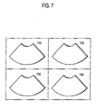
- the image processor 150 extracts slab data corresponding to each of the slabs from the 3-dimensional ultrasound image data at step S 190 and carries out image rendering for the extracted slab data at step S200, thereby forming 3-dimensional slab images 710 to 740 as shown in Fig. 7.
- the image rendering may be performed by using a volume rendering technique such as a ray casting technique or the like.
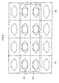
- the image processor 150 extracts multiple sectional plane images included within the 3-dimensional region 520 set by lines 520A and 520B from the multiple sectional plane images shown in Fig. 4. Then, the extracted multiple sectional plane images 810 are selected as shown in Fig. 8 at step S210. Subsequently, a region of interest (ROI) 820 is set on each of the selected multiple sectional plane images 810 at step S220 and then the image processor 150 extracts data corresponding to the ROI from the 3-dimensional ultrasound image data. The image processor 150 carries out an image rendering process for the extracted data at step S230, thereby forming a 3-dimensional ultrasound image.
- ROI region of interest
- the 3-dimensional region to form the partial 3-dimensional ultrasound image which contains the images desired for diagnosis, is set on the sectional plane image, the user can easily select the desirable diagnosis region in the 3-dimensional ultrasound image in accordance with the present invention.
- the 3-dimensional ultrasound image can be formed more quickly.
Landscapes
- Health & Medical Sciences (AREA)
- Engineering & Computer Science (AREA)
- Life Sciences & Earth Sciences (AREA)
- Physics & Mathematics (AREA)
- Radar, Positioning & Navigation (AREA)
- Remote Sensing (AREA)
- Biomedical Technology (AREA)
- Molecular Biology (AREA)
- Biophysics (AREA)
- Nuclear Medicine, Radiotherapy & Molecular Imaging (AREA)
- Pathology (AREA)
- Radiology & Medical Imaging (AREA)
- Veterinary Medicine (AREA)
- Heart & Thoracic Surgery (AREA)
- Medical Informatics (AREA)
- Public Health (AREA)
- Surgery (AREA)
- Animal Behavior & Ethology (AREA)
- General Health & Medical Sciences (AREA)
- General Physics & Mathematics (AREA)
- Computer Networks & Wireless Communication (AREA)
- Acoustics & Sound (AREA)
- Ultra Sonic Daignosis Equipment (AREA)
- Image Processing (AREA)
- Image Generation (AREA)
- Image Analysis (AREA)
Abstract
Description
- The present invention generally relates to image forming systems, and more particularly to a system and a method for forming a 3-dimensional image by using multiple sectional plane images of a target object.
- An ultrasound diagnostic system has become an important and popular diagnostic tool since it has a wide range of applications. Specifically, due to its non-invasive and non-destructive nature, the ultrasound diagnostic system has been extensively used in the medical profession. Modem high-performance ultrasound diagnostic systems and techniques are commonly used to produce two or three-dimensional diagnostic images of internal features of an object (e.g., human organs).
- The ultrasound diagnostic system generally uses a wide bandwidth transducer to transmit and receive ultrasound signals. The ultrasound diagnostic system forms images of human internal tissues by electrically exciting an acoustic transducer element or an array of acoustic transducer elements to generate ultrasound signals that travel into the body. The ultrasound signals produce ultrasound echo signals since they are reflected from body tissues, which appear as discontinuities to the propagating ultrasound signals. Various ultrasound echo signals return to the transducer element and are converted into electrical signals, which are amplified and processed to produce ultrasound data for an image of the tissues. The ultrasound diagnostic system is very important in the medical field since it provides physicians with real-time and high-resolution images of human internal features without the need for invasive observation techniques such as surgery.
- The conventional ultrasound diagnostic system acquires 3-dimensional ultrasound data from ultrasound echo signals and forms a 3-dimensional ultrasound image based on the acquired 3-dimensional ultrasound data. In such a case, the entire 3-dimensional ultrasound data are used to form one 3-dimensional ultrasound image, even if the desired portions are different from each other, according to the users' or specific diagnostic purposes. Therefore, such ultrasound diagnostic system is highly inconvenient since the user is required to find a desirable portion in the 3-dimensional ultrasound image.
- Also, since the conventional ultrasound diagnostic system uses the entire 3-dimensional ultrasound data to form the 3-dimensional ultrasound image, it takes a very long time to form the 3-dimensional ultrasound image.
- The present invention provides a system and a method for setting a region of interest on multiple sectional plane images, extracting data included in the region of interest from 3-dimensional ultrasound image data and performing image rendering for the extracted data, thereby forming a desirable 3-dimensional ultrasound image.
- According to one aspect of the present invention, there is provided a system for forming 3-dimensional images, including: an image data forming unit for forming 3-dimensional volume data based on image signals; an image forming unit for forming multiple sectional plane images sliced along a predetermined direction in a 3-dimensional image, the image forming unit being configured to form at least one 3-dimensional image with partial 3-dimensional volume data selected by using the multiple sectional plane images from the 3-dimensional volume data; and a displaying unit for displaying the multiple sectional plane images and the 3-dimensional image.
- According to another aspect of the present invention, there is provided a method of forming 3-dimensional images, including the steps of: a) forming 3-dimensional volume data based on image signals; b) forming multiple sectional plane images sliced along a predetermined direction in a 3-dimensional image; c) selecting one of the multiple section plane images; d) forming a reference sectional plane image orthogonal to the selected sectional plane image; e) setting a predetermined region on the reference sectional plane image; l) extracting data included in the predetermined region from the 3-dimensional volume data; g) performing image rendering for the extracted data; and h) forming at least one 3-dimensional image.
- The above and other objects and features of the present invention will become apparent from the following descriptions of preferred embodiments given in conjunction with the accompanying drawings, in which:
- Fig. 1 is a block diagram showing an ultrasound diagnostic system constructed in accordance with the present invention;
- Fig. 2 is a flowchart illustrating the operation of an image processor constructed in accordance with the present invention;
- Fig. 3 is a schematic diagram showing examples of sectional plane images in 3-dimensional ultrasound image data;
- Fig. 4 shows multiple sectional plane images and a reference sectional plane image in accordance with the present invention;
- Fig. 5 shows an example of setting a 3-dimensional region on the reference sectional plane image in accordance with the present invention;
- Fig. 6 shows an example of slicing a 3-dimensional region on the reference sectional plane image in accordance with the present invention;
- Fig. 7 shows an example of displaying slab images in accordance with the present invention; and
- Fig. 8 shows an example of displaying the extracted sectional plane images included in the 3-dimensional region selected on a reference sectional image in accordance with the present invention.
- Fig. 1 is a block diagram showing an ultrasound
diagnostic system 100, which is constructed in accordance with the present invention. The ultrasounddiagnostic system 100 of the present invention includes a probe I 10, a beam former 120, animage signal processor 130, ascan converter 140, animage processor 150, adisplay unit 160 and aninput unit 170. The ultrasounddiagnostic system 100 further includes a memory (not shown) for storing 2-dimensional ultrasound image data and 3-dimensional ultrasound image data. Also, theimage signal processor 130 and theimage processor 150 may be provided as one processor. - The
probe 110 includes a 1-dimensional or a 2-dimensional array transducer 112. The transmit signals, which are appropriately delayed in the beam former 120 to form an ultrasound beam, are transmitted to thearray transducer 112. Then, the focused ultrasound beam, which is produced in response to the transmit signals, is transmitted along a scan line of a target object (not shown). Theprobe 110 receives ultrasound echo signals reflected from the target object and converts the ultrasound echo signals into electrical signals (hereinafter referred to as receive signals). The receive signals are transmitted to the beam former 120. - The beam former 120 provides delays of transmit signals to be transmitted to the
array transducer 112 included in theprobe 110 such that the ultrasound signals outputted from thearray transducer 112 arc focused on a focal point. Further, thebeam former 120 focuses the receive signals, which are received from thearray transducer 112 included in theprobe 110, in consideration of the delays with which the echo signals are arrived at each transducer. It then outputs a focused receive beam representing an energy level of the ultrasound echo signal reflected from the focal point. - The image signal processor 130 (e.g., a digital signal processor (DSP)) performs envelop detection for detecting intensities of the focused receive signals to form ultrasound image data. That is, the
image signal processor 130 forms 3-dimensional ultrasound image data based on the receive focused signals acquired from each focal point and position information of a plurality of focal points on each scan line. The 3-dimensional ultrasound image data incl ude coordinates information of each focal point, angle information of each scan line and intensity information of the echo signals received at each focal point. - The
scan converter 140 scan-converts the 3-dimensional ultrasound image data to a data format capable of being displayed on a screen of thedisplay unit 160. Theimage processor 150 forms multiple sectional plane images in response to a plane selecting instruction, which is inputted by a user to determine an image slicing direction of sectional plane images. Also, theimage processor 150 forms a partial 3-dimensional ultrasound image corresponding to a predetermined region of the 3-dimensional ultrasound image data in response to a region setting instruction inputted from the user. The 3-dimensional ultrasound image is displayed on thedisplay unit 160. - The
input unit 170 receives user's selections to transmit the plane selecting instruction and the region setting instruction to theimage processor 150. Theinput unit 170 may be a mouse, a track ball, a keyboard, a touch pad or the like. - Hereinafter, the operation of the
image processor 150 will be described in detail with reference to Figs. 2 to 8. Fig. 2 is a flowchart that shows the operation of the image processor constructed in accordance with the present invention. - Referring now to Fig. 2, after forming the 3-dimensional ultrasound image data based on the ultrasound echo signals received by the
probe 110 atstep S 110, theimage processor 150 forms multiple sectional plane images in a predetermined image slicing direction, which is determined in response to the plane selecting instruction at step S120. One of the multiple sectional plane images is selected at step S130. The selected sectional plane image may contain images, which are desirable for diagnosis. A reference sectional plane image, which is orthogonal to the selected sectional plane image, is formed at step S140. The reference sectional plane image is used for setting a region representing the width of a partial 3-dimensional ultrasound image (hereinafter referred to as a 3-dimensional region) in the 3-diniensional ultrasound image data. The partial 3-dimensional ultrasound image contains images for diagnosis. For example, as illustrated in Fig. 3, if the selected sectional plane image is an A sectional plane image, then a B sectional plane image or a C sectional plane image becomes a reference sectional plane image. Also, if the selected sectional plane image is the B sectional plane image, then the C sectional plane image or the A sectional plane image becomes a reference sectional plane image. Further, if the selected sectional plane image is the C sectional plane image, then the A sectional plane image or the B sectional plane image becomes a reference sectional plane image. - The multiple sectional plane images are displayed on a multiple sectional plane
image displaying part 210, whereas the reference sectional plane image is displayed on a reference sectional planeimage displaying part 220, as shown in Fig. 4 atstep S 150. The 3-dimensional region is set on the reference sectional plane image at step S160. As shown in Fig. 5, in order to set the 3-dimensional region, acenter line 510 that represents a position of the selected sectional plane image is indicated on the referencesectional plane image 500. The 3-dimensional region 520 is set with twolines sectional plane image 500 to have an identical size at right and left sides of thecenter line 510. Thelines 520 for setting the 3-dimensional region may be straight lines or oblique lines. - After setting the 3-dimensional region at step S160, it is determined whether to slice the 3-dimensional region at step S170. If it is determined to slice the 3-dimensonal region, then the number of slabs produced by slicing the 3-dimensional region is determined at step S180. Fig. 6 shows the sliced 3-
dimensional region 520 on the referencesectional plane image 500. As shown in Fig. 6, four slabs are produced by slicing the 3-dimensional region alongslice lines 610 and thecenter line 510. The width of each slab may be identical to each other in accordance with the preferred embodiment of the present invention. Also, the width of each slab may be adjusted. Theimage processor 150 extracts slab data corresponding to each of the slabs from the 3-dimensional ultrasound image data atstep S 190 and carries out image rendering for the extracted slab data at step S200, thereby forming 3-dimensional slab images 710 to 740 as shown in Fig. 7. The image rendering may be performed by using a volume rendering technique such as a ray casting technique or the like. - Further, if it is determined not to slice the 3-dimensional region at
step S 170, then theimage processor 150 extracts multiple sectional plane images included within the 3-dimensional region 520 set bylines sectional plane images 810 are selected as shown in Fig. 8 at step S210. Subsequently, a region of interest (ROI) 820 is set on each of the selected multiplesectional plane images 810 at step S220 and then theimage processor 150 extracts data corresponding to the ROI from the 3-dimensional ultrasound image data. Theimage processor 150 carries out an image rendering process for the extracted data at step S230, thereby forming a 3-dimensional ultrasound image. - Since the 3-dimensional region to form the partial 3-dimensional ultrasound image, which contains the images desired for diagnosis, is set on the sectional plane image, the user can easily select the desirable diagnosis region in the 3-dimensional ultrasound image in accordance with the present invention.
- Also, since a portion of 3-dimensional ultrasound data is used to form a 3-dimensional ultrasound image, the 3-dimensional ultrasound image can be formed more quickly.
- While the present invention has been described and illustrated with respect to a preferred embodiment of the invention, it will be apparent to those skilled in the art that variations and modifications are possible without deviating from the broad principles and teachings of the present invention, which should be limited solely by the scope of the claims appended hereto.
Claims (11)
- A system for forming 3-dimensional images, comprising:an image data forming unit for forming 3-dimensional volume data based on image signals;an image forming unit for forming multiple sectional plane images sliced along a predetermined direction in a 3-dimensional image, the image forming unit being configured to form at least one 3-dimensional image with partial 3-dimensional volume data selected by using the multiple sectional plane images from the 3-dimensional volume data; anda displaying unit for displaying the multiple sectional plane images and the 3-dimensional image.
- The system of Claim 1, wherein the 3-dimensional image is a 3-dimensional ultrasound image.
- The system of Claim 1, further comprising an input unit for receiving a sectional plane selecting instruction and a region setting instruction from a user.
- The system of Claim 3, wherein the image forming unit includes:a first image forming unit for forming the multiple sectional plane images in the predetermined direction in response to the sectional plane selecting instruction;a second image forming unit for forming a reference sectional plane image orthogonal to the multiple sectional plane images;a region setting unit for setting a predetermined region on the reference sectional plane image in response to the region setting instruction;a first data extracting unit for extracting data included in the predetermined region from the 3-dimensional data; anda first image rendering unit for rendering the extracted data to form the 3-dimensional image.
- The system of Claim 4, wherein the image forming unit further includes:a first determining unit for determining whether to slice an image included in the predetermined region;a second determining unit for determining the number of slabs produced by slicing the image;a second data extracting unit for extracting slab data corresponding to each of the slabs from the 3-dimensional volume data; anda second image rendering unit for rendering the slab data to form 3-dimensional slab images.
- A method of forming 3-dimensional images, comprising the steps of:a) forming 3-dimensional volume data based on image signals;b) forming multiple sectional plane images sliced along a predetermined direction in a 3-dimensional image;c) selecting one of the multiple section plane images;d) forming a reference sectional plane image orthogonal to the selected sectional plane image;e) setting a predetermined region on the reference sectional plane image;f) extracting data included in the predetermined region from the 3-dimensional volume data;g) performing image rendering for the extracted data; andh) forming at least one 3-dimensional image.
- The method of Claim 6, wherein the 3-dimensional image is a 3-dimensional ultrasound image.
- The method of Claim 6, wherein the step b) includes the steps of:b1) receiving a sectional plane image selecting instruction to determine a direction of the multiple sectional plane images in the 3-dimensional image; andb2) forming the multiple sectional plane images in response to the sectional plane image selecting instruction.
- The method of Claim 8, wherein the step e) includes the steps of:c1) receiving a region setting instruction to determine a region for forming the 3-duninsional image in the 3-dimensional volume data; ande2) setting the region by referring to a center line indicating a position of the selected sectional plane image on the reference sectional plane image in response to the region setting instruction.
- The method of Claim 9, wherein the step e) further includes the steps of:e3) determining whether to slice the region; ande4) if it is determined to slice the region, determining the number of slabs produced by slicing the region;e5) at step e3), if it is determined not to slice the region, extracting sectional plane images included in the region; ande6) setting a region of interest (ROI) on each of the extracted sectional plane images.
- The method of Claim 10, wherein the step f) includes the steps of:f1) extracting slab data corresponding to the slabs determined at step e4); andf2) extracting data included in the ROI set at step e6).
Applications Claiming Priority (1)
| Application Number | Priority Date | Filing Date | Title |
|---|---|---|---|
| KR1020050097352A KR100880125B1 (en) | 2005-10-17 | 2005-10-17 | Image Processing System and Method for Forming 3D Image Using Multiple Section Images |
Publications (2)
| Publication Number | Publication Date |
|---|---|
| EP1775601A1 true EP1775601A1 (en) | 2007-04-18 |
| EP1775601B1 EP1775601B1 (en) | 2011-03-16 |
Family
ID=37602989
Family Applications (1)
| Application Number | Title | Priority Date | Filing Date |
|---|---|---|---|
| EP06021475A Active EP1775601B1 (en) | 2005-10-17 | 2006-10-13 | System and method for forming 3-dimensional images using multiple sectional plane images |
Country Status (5)
| Country | Link |
|---|---|
| US (1) | US20070100238A1 (en) |
| EP (1) | EP1775601B1 (en) |
| JP (1) | JP4978148B2 (en) |
| KR (1) | KR100880125B1 (en) |
| DE (1) | DE602006020669D1 (en) |
Cited By (4)
| Publication number | Priority date | Publication date | Assignee | Title |
|---|---|---|---|---|
| EP2238913A1 (en) | 2009-04-01 | 2010-10-13 | Medison Co., Ltd. | 3-dimensional ultrasound image provision using volume slices in an ultrasound system |
| KR101117003B1 (en) | 2008-12-02 | 2012-03-19 | 삼성메디슨 주식회사 | Ultrasound system and method of providing 3-dimensional ultrasound images using volume slices |
| EP2333576A3 (en) * | 2009-12-09 | 2013-07-10 | Medison Co., Ltd. | Providing a three-dimensional ultrasound image based on a sub region of interest in an ultrasound system |
| US9131918B2 (en) | 2008-12-02 | 2015-09-15 | Samsung Medison Co., Ltd. | 3-dimensional ultrasound image provision using volume slices in an ultrasound system |
Families Citing this family (8)
| Publication number | Priority date | Publication date | Assignee | Title |
|---|---|---|---|---|
| JP2009125181A (en) * | 2007-11-21 | 2009-06-11 | Hitachi Medical Corp | Ultrasonic diagnostic system |
| KR101014552B1 (en) * | 2008-11-19 | 2011-02-16 | 주식회사 메디슨 | Ultrasound System and 3D Ultrasound Image Formation Method |
| JP5762076B2 (en) | 2010-03-30 | 2015-08-12 | 株式会社東芝 | Ultrasonic diagnostic apparatus, ultrasonic image processing apparatus, and medical image diagnostic apparatus |
| KR101501518B1 (en) * | 2012-06-11 | 2015-03-11 | 삼성메디슨 주식회사 | The method and apparatus for displaying a two-dimensional image and a three-dimensional image |
| KR101665124B1 (en) | 2014-08-25 | 2016-10-12 | 삼성메디슨 주식회사 | Ultrasonic imaging apparatus and for the same |
| KR101900776B1 (en) * | 2017-12-14 | 2018-09-20 | 한국과학기술정보연구원 | Method and apparatus for visualizing of multi-slice |
| KR102750602B1 (en) * | 2020-02-04 | 2025-01-10 | 삼성메디슨 주식회사 | Ultrasonic imaging apparatus and control method thereof |
| US12307556B2 (en) * | 2021-03-22 | 2025-05-20 | GE Precision Healthcare LLC | Automatic model-based navigation system and method for ultrasound images |
Citations (5)
| Publication number | Priority date | Publication date | Assignee | Title |
|---|---|---|---|---|
| EP0809119A2 (en) * | 1996-05-21 | 1997-11-26 | Aloka Co., Ltd. | Ultrasound image processing apparatus and method of forming and displaying ultra sound images by the apparatus |
| WO2000058754A1 (en) * | 1999-03-31 | 2000-10-05 | General Electric Company | Three-dimensional ultrasound data display using multiple cut planes |
| US6245017B1 (en) * | 1998-10-30 | 2001-06-12 | Kabushiki Kaisha Toshiba | 3D ultrasonic diagnostic apparatus |
| WO2002043801A2 (en) * | 2000-11-24 | 2002-06-06 | U-Systems, Inc. | Method and system for ultrasound breast cancer screening |
| WO2005063125A1 (en) * | 2003-12-22 | 2005-07-14 | Koninklijke Philips Electronics N.V. | System for guiding a medical instrument in a patient body |
Family Cites Families (10)
| Publication number | Priority date | Publication date | Assignee | Title |
|---|---|---|---|---|
| JP3382675B2 (en) * | 1993-08-05 | 2003-03-04 | オリンパス光学工業株式会社 | Ultrasound imaging diagnostic equipment |
| US5782762A (en) * | 1994-10-27 | 1998-07-21 | Wake Forest University | Method and system for producing interactive, three-dimensional renderings of selected body organs having hollow lumens to enable simulated movement through the lumen |
| US5920319A (en) * | 1994-10-27 | 1999-07-06 | Wake Forest University | Automatic analysis in virtual endoscopy |
| WO1997000482A1 (en) * | 1995-06-15 | 1997-01-03 | The Regents Of The University Of Michigan | Method and apparatus for composition and display of three-dimensional image from two-dimensional ultrasound |
| JP3878343B2 (en) * | 1998-10-30 | 2007-02-07 | 株式会社東芝 | 3D ultrasonic diagnostic equipment |
| US6487432B2 (en) * | 2000-12-04 | 2002-11-26 | Ge Medical Systems Global Technologies Company Llc | Method and system for selecting and displaying medical image data |
| JP2005102945A (en) * | 2003-09-30 | 2005-04-21 | Ssb:Kk | Biotissue multidimensional visualization equipment |
| KR100751852B1 (en) * | 2003-12-31 | 2007-08-27 | 주식회사 메디슨 | Apparatus and method for displaying slices of a target object utilizing 3 dimensional ultrasound data thereof |
| KR100697728B1 (en) * | 2004-10-22 | 2007-03-21 | 주식회사 메디슨 | Apparatus and method for improving image quality of ultrasonic cross-sectional images |
| EP1847222B1 (en) * | 2005-02-09 | 2011-04-13 | Hitachi Medical Corporation | Ultrasonographic device and ultrasonographic method |
-
2005
- 2005-10-17 KR KR1020050097352A patent/KR100880125B1/en not_active Expired - Lifetime
-
2006
- 2006-10-13 DE DE602006020669T patent/DE602006020669D1/en active Active
- 2006-10-13 EP EP06021475A patent/EP1775601B1/en active Active
- 2006-10-16 US US11/549,835 patent/US20070100238A1/en not_active Abandoned
- 2006-10-17 JP JP2006282729A patent/JP4978148B2/en not_active Expired - Fee Related
Patent Citations (5)
| Publication number | Priority date | Publication date | Assignee | Title |
|---|---|---|---|---|
| EP0809119A2 (en) * | 1996-05-21 | 1997-11-26 | Aloka Co., Ltd. | Ultrasound image processing apparatus and method of forming and displaying ultra sound images by the apparatus |
| US6245017B1 (en) * | 1998-10-30 | 2001-06-12 | Kabushiki Kaisha Toshiba | 3D ultrasonic diagnostic apparatus |
| WO2000058754A1 (en) * | 1999-03-31 | 2000-10-05 | General Electric Company | Three-dimensional ultrasound data display using multiple cut planes |
| WO2002043801A2 (en) * | 2000-11-24 | 2002-06-06 | U-Systems, Inc. | Method and system for ultrasound breast cancer screening |
| WO2005063125A1 (en) * | 2003-12-22 | 2005-07-14 | Koninklijke Philips Electronics N.V. | System for guiding a medical instrument in a patient body |
Cited By (5)
| Publication number | Priority date | Publication date | Assignee | Title |
|---|---|---|---|---|
| KR101117003B1 (en) | 2008-12-02 | 2012-03-19 | 삼성메디슨 주식회사 | Ultrasound system and method of providing 3-dimensional ultrasound images using volume slices |
| US9131918B2 (en) | 2008-12-02 | 2015-09-15 | Samsung Medison Co., Ltd. | 3-dimensional ultrasound image provision using volume slices in an ultrasound system |
| EP2238913A1 (en) | 2009-04-01 | 2010-10-13 | Medison Co., Ltd. | 3-dimensional ultrasound image provision using volume slices in an ultrasound system |
| US9649095B2 (en) | 2009-04-01 | 2017-05-16 | Samsung Medison Co., Ltd. | 3-dimensional ultrasound image provision using volume slices in an ultrasound system |
| EP2333576A3 (en) * | 2009-12-09 | 2013-07-10 | Medison Co., Ltd. | Providing a three-dimensional ultrasound image based on a sub region of interest in an ultrasound system |
Also Published As
| Publication number | Publication date |
|---|---|
| KR100880125B1 (en) | 2009-01-23 |
| KR20070041825A (en) | 2007-04-20 |
| US20070100238A1 (en) | 2007-05-03 |
| DE602006020669D1 (en) | 2011-04-28 |
| JP2007111532A (en) | 2007-05-10 |
| JP4978148B2 (en) | 2012-07-18 |
| EP1775601B1 (en) | 2011-03-16 |
Similar Documents
| Publication | Publication Date | Title |
|---|---|---|
| US20080063305A1 (en) | Apparatus and method for displaying an ultrasound image | |
| CN102028500B (en) | Ultrasonic diagnosis apparatus, ultrasonic image processing apparatus, ultrasonic image processing method | |
| US8103066B2 (en) | Ultrasound system and method for forming an ultrasound image | |
| JP4585326B2 (en) | Ultrasonic imaging apparatus and ultrasonic imaging method | |
| US20060173327A1 (en) | Ultrasound diagnostic system and method of forming arbitrary M-mode images | |
| JP5253893B2 (en) | Medical image processing apparatus, ultrasonic diagnostic apparatus, and ultrasonic image acquisition program | |
| EP3378405A1 (en) | Volume rendered ultrasound imaging | |
| JP2008136860A (en) | Ultrasonic diagnostic apparatus and image processing program thereof | |
| JP2011062524A (en) | Ultrasonic system and method for measuring three-dimensional distance | |
| JP2009207899A (en) | System and method for processing ultrasound image | |
| US20070100238A1 (en) | System and method for forming 3-dimensional images using multiple sectional plane images | |
| EP1780671B1 (en) | Image processing system and method for editing contours of a target object using multiple sectional images | |
| JP2006218210A (en) | Ultrasonic diagnostic apparatus, ultrasonic image generation program, and ultrasonic image generation method | |
| EP1739627B1 (en) | Method and apparatus for displaying a color flow image in an ultrasound diagnostic system | |
| JP2001157677A (en) | Ultrasonic diagnostic apparatus | |
| JP5060141B2 (en) | Ultrasonic diagnostic equipment | |
| EP2196151A1 (en) | Ultrasound system and method for forming a plurality of three-dimensional ultrasound images | |
| JP2009034262A (en) | Ultrasonic diagnostic apparatus | |
| KR100769546B1 (en) | 3D ultrasound image forming method and ultrasonic diagnostic system using 2D ultrasound image | |
| KR100875620B1 (en) | Ultrasound Imaging Systems and Methods | |
| JP5348829B2 (en) | Ultrasonic diagnostic apparatus, ultrasonic image display method, and ultrasonic image display program | |
| KR100880399B1 (en) | Ultrasound System and Method for Forming Ultrasound Images | |
| KR101055528B1 (en) | Ultrasound system and method for providing OH | |
| JPH03133436A (en) | Ultrasonic diagnostic device | |
| KR20080010035A (en) | Ultrasound System and Method for Forming Ultrasound Images |
Legal Events
| Date | Code | Title | Description |
|---|---|---|---|
| PUAI | Public reference made under article 153(3) epc to a published international application that has entered the european phase |
Free format text: ORIGINAL CODE: 0009012 |
|
| AK | Designated contracting states |
Kind code of ref document: A1 Designated state(s): AT BE BG CH CY CZ DE DK EE ES FI FR GB GR HU IE IS IT LI LT LU LV MC NL PL PT RO SE SI SK TR |
|
| AX | Request for extension of the european patent |
Extension state: AL BA HR MK YU |
|
| 17P | Request for examination filed |
Effective date: 20070924 |
|
| 17Q | First examination report despatched |
Effective date: 20071025 |
|
| AKX | Designation fees paid |
Designated state(s): DE FR IT |
|
| GRAP | Despatch of communication of intention to grant a patent |
Free format text: ORIGINAL CODE: EPIDOSNIGR1 |
|
| GRAS | Grant fee paid |
Free format text: ORIGINAL CODE: EPIDOSNIGR3 |
|
| GRAA | (expected) grant |
Free format text: ORIGINAL CODE: 0009210 |
|
| AK | Designated contracting states |
Kind code of ref document: B1 Designated state(s): DE FR IT |
|
| REF | Corresponds to: |
Ref document number: 602006020669 Country of ref document: DE Date of ref document: 20110428 Kind code of ref document: P |
|
| REG | Reference to a national code |
Ref country code: DE Ref legal event code: R096 Ref document number: 602006020669 Country of ref document: DE Effective date: 20110428 |
|
| PLBE | No opposition filed within time limit |
Free format text: ORIGINAL CODE: 0009261 |
|
| STAA | Information on the status of an ep patent application or granted ep patent |
Free format text: STATUS: NO OPPOSITION FILED WITHIN TIME LIMIT |
|
| 26N | No opposition filed |
Effective date: 20111219 |
|
| REG | Reference to a national code |
Ref country code: DE Ref legal event code: R097 Ref document number: 602006020669 Country of ref document: DE Effective date: 20111219 |
|
| REG | Reference to a national code |
Ref country code: FR Ref legal event code: PLFP Year of fee payment: 11 |
|
| REG | Reference to a national code |
Ref country code: FR Ref legal event code: PLFP Year of fee payment: 12 |
|
| REG | Reference to a national code |
Ref country code: FR Ref legal event code: PLFP Year of fee payment: 13 |
|
| PGFP | Annual fee paid to national office [announced via postgrant information from national office to epo] |
Ref country code: IT Payment date: 20250909 Year of fee payment: 20 |
|
| PGFP | Annual fee paid to national office [announced via postgrant information from national office to epo] |
Ref country code: FR Payment date: 20250909 Year of fee payment: 20 |
|
| PGFP | Annual fee paid to national office [announced via postgrant information from national office to epo] |
Ref country code: DE Payment date: 20250908 Year of fee payment: 20 |