EP1775566A2 - System for sealing variable gaps for scale models tested in an aerodynamic tunnel - Google Patents
System for sealing variable gaps for scale models tested in an aerodynamic tunnel Download PDFInfo
- Publication number
- EP1775566A2 EP1775566A2 EP06380213A EP06380213A EP1775566A2 EP 1775566 A2 EP1775566 A2 EP 1775566A2 EP 06380213 A EP06380213 A EP 06380213A EP 06380213 A EP06380213 A EP 06380213A EP 1775566 A2 EP1775566 A2 EP 1775566A2
- Authority
- EP
- European Patent Office
- Prior art keywords
- piece
- recess
- sealing according
- back wall
- packing
- Prior art date
- Legal status (The legal status is an assumption and is not a legal conclusion. Google has not performed a legal analysis and makes no representation as to the accuracy of the status listed.)
- Withdrawn
Links
Images




Classifications
-
- F—MECHANICAL ENGINEERING; LIGHTING; HEATING; WEAPONS; BLASTING
- F16—ENGINEERING ELEMENTS AND UNITS; GENERAL MEASURES FOR PRODUCING AND MAINTAINING EFFECTIVE FUNCTIONING OF MACHINES OR INSTALLATIONS; THERMAL INSULATION IN GENERAL
- F16J—PISTONS; CYLINDERS; SEALINGS
- F16J15/00—Sealings
- F16J15/02—Sealings between relatively-stationary surfaces
- F16J15/021—Sealings between relatively-stationary surfaces with elastic packing
- F16J15/028—Sealings between relatively-stationary surfaces with elastic packing the packing being mechanically expanded against the sealing surface
-
- F—MECHANICAL ENGINEERING; LIGHTING; HEATING; WEAPONS; BLASTING
- F16—ENGINEERING ELEMENTS AND UNITS; GENERAL MEASURES FOR PRODUCING AND MAINTAINING EFFECTIVE FUNCTIONING OF MACHINES OR INSTALLATIONS; THERMAL INSULATION IN GENERAL
- F16J—PISTONS; CYLINDERS; SEALINGS
- F16J15/00—Sealings
- F16J15/16—Sealings between relatively-moving surfaces
-
- F—MECHANICAL ENGINEERING; LIGHTING; HEATING; WEAPONS; BLASTING
- F16—ENGINEERING ELEMENTS AND UNITS; GENERAL MEASURES FOR PRODUCING AND MAINTAINING EFFECTIVE FUNCTIONING OF MACHINES OR INSTALLATIONS; THERMAL INSULATION IN GENERAL
- F16J—PISTONS; CYLINDERS; SEALINGS
- F16J15/00—Sealings
- F16J15/02—Sealings between relatively-stationary surfaces
- F16J15/06—Sealings between relatively-stationary surfaces with solid packing compressed between sealing surfaces
- F16J15/061—Sealings between relatively-stationary surfaces with solid packing compressed between sealing surfaces with positioning means
-
- G—PHYSICS
- G01—MEASURING; TESTING
- G01M—TESTING STATIC OR DYNAMIC BALANCE OF MACHINES OR STRUCTURES; TESTING OF STRUCTURES OR APPARATUS, NOT OTHERWISE PROVIDED FOR
- G01M9/00—Aerodynamic testing; Arrangements in or on wind tunnels
- G01M9/08—Aerodynamic models
Definitions
- the present invention belongs to the field of systems for sealing intended for filling spaces and/or gaps that are variable in both shape and size, in test models in wind tunnels, for studying the aerodynamic properties of exterior surfaces of vehicles such as aircraft, cars, trains, etc.
- the invention applies to the sector of systems for sealing for spaces that are variable in shape and size existing between the surface of a moving element and the surface of a fixed element in test models in the aeronautical sector.
- the sealing is generally done with resin, foam, self-adhesive tape or rubber seals, which are positioned between the pieces sealing the space existing between them.
- a device was therefore desirable that would solve the problems existing in the prior art.
- the present invention has the aim of overcoming the drawbacks of the prior art pointed out above by means of a system of sealing of spaces that are variable in size and shape in models tested in a wind tunnel.
- the objective of this invention is to place a seal in variable spaces which can adapt itself to a change in both size and shape of the space. In this way, it would not be necessary to redo the seal every time the geometry of the space changes since the seal adapts itself to the different shapes and sizes of the space.
- This invention manages to reduce the time for changing from one test arrangement to another in different positions for being tested.
- Said system for sealing comprises packing means in order to at least partially pack a space existing between two pieces of a model, with one of these pieces able to be moving.
- the invention presents the following characteristics:
- either an array of coil springs or a set of strips with at least one elastic section can be used as spring elements pushing against the packing body, resting on the packing body and pushing it against the piece thus sealing the space.
- One of these methods consists of a piercing body located in the end opposite to that where pressure is exerted on the packing body, which becomes nailed to the wall of the recess in which the spring element is located.
- the means of attachment consist of a threaded body which, instead of piercing, is screwed to the wall of the recess, thereby securing the spring element.
- the spring element and the means of attachment can be produced in a single piece, or instead in two different pieces. In the latter case, if the spring element is a coil spring, it will grasp the attachment element, and if it is a flexible strip it will be joined to the attachment element by conventional means, for example by soldering.
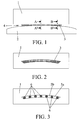
- Figures 1 and 2 show a general arrangement of the invention, in which between a first piece 1, which remains fixed, and a second piece 2, whose position can be varied in different tests, there exists a space 4 which is sealed with a packing body 3.
- Said packing body 3 is manufactured from a flexible material, such as for example rubber or resin, in order to be able to adapt itself to the change in shape of the space that is produced when the second moving piece 2 changes its position. In this way, the sealing keeps the space closed even though the latter changes shape or size owing to the movement of the pieces.
- the packing body 3 fits into a recess 5 made in the first or second piece 1 or 2 in such a way that the front part of the packing body 3 emerges from the front end of the recess 5a.
- Figures 2 and 3 show a first embodiment of the recess 5, in which said recess 5 is made in the first piece 1, which is the fixed piece of the model.
- spring elements 6, 7 located in the back wall of the recess 5b, which is opposite to the front side 5a, are some spring elements 6, 7 which have the purpose of pushing the packing element 3 against the surface of the second piece 2 of the model. In this way, the packing element 3 is at all times in contact with the surface of the second piece 2 keeping the space 4 closed. Moreover, these spring elements 6, 7 permit the packing element to adjust itself to variations in the size of the space 4, and the packing element 3 can also be used for different arrangements of the pieces 1 and 2, and different relative displacements between them, at all time keeping the said space 4 at least partially packed.
- spring elements In order to exert the function of pushing on the packing element against the surface of the piece, different spring elements can be used. In a first embodiment of these spring elements, they consist of an array of coil springs 6, as can be seen in figures 3-7, 12-13. These coil springs 6 are attached to the first piece 1 in the back wall 5b of the recess 5 and they push the packing element 3 against the surface of the second piece 2, keeping the space 4 sealed.
- the advantage of this embodiment is the possibility of being able to adjust the width of the spring to the size of the gap of the recess 5. This provides greater stability in the attachment of the coil spring 6 to the interior of the recess 5, along with less possibility of the latter becoming displaced due to possible relative movements between the first piece 1 and the second piece 2. Moreover, as there exists a greater contour in the support surface of the coil spring 6 against the packing element 3, the seal 4 of the space 5 existing between the first piece 1 and the second piece 2 will be more effective.
- FIG. 8-11 B A second embodiment of the spring elements is illustrated in figures 8-11 B.
- the coil spring 6 is replaced by an elastic strip 7.
- Said elastic strip 7 possesses an elastic section 7a which exerts pressure on the packing body 3 via a support section 7c.
- the advantage of using an elastic strip 7 in the invention, rather than a coil spring 6, is the greater simplicity of manufacture when dealing with very small sizes.
- Figures 4, 6 and 7 show a first embodiment of those means of attachment for the coil spring 6, in which a piercing body 6a is used, which is nailed to the back wall 5b, being retained therein.
- the advantage of this embodiment is its simplicity of manufacture and assembly and, therefore, lower cost.
- Figure 5 shows a second embodiment of the attachment applied to the coil spring 6, in which a threaded body 6b, is used which is screwed to the back wall 5b and retained therein.
- the advantage of this second embodiment is that the attachment is firmer and more secure, which avoids possible damage to the back wall 5b which could be occasioned in the case of using the piercing body 6a and the latter is nailed too far into the back wall.
- FIGS 8, 9, 10 and 11A show a first embodiment of the means of attachment applied to the elastic strip 7 in which a piercing projection 7b is used. Said piercing projection 7b is nailed into the back wall 5b, being retained therein.
- the same advantages of simplicity of manufacture and assembly as were obtained with the attachment arrangement with a piercing body 6a for the coil spring 6 are obtained in with this attachment arrangement with a piercing projection 7b for the elastic strip 7.
- Figure 11B shows a second embodiment of the means of attachment applied to the elastic strip 7 in which a threaded projection 7d is used.
- Said threaded projection 7d is screwed to the back wall 5b being retained therein and achieving an attachment that presents the same advantages of firmness and security as those offered by the embodiment by means of coil spring 6 and threaded body 6b.
- the attachment elements 6a, 6b, 7b and 7d, and the spring elements 6 and 7, can be made in a single piece or instead two different pieces.
- Figures 4 and 5 show an embodiment of the union of the coil spring 6 and its attachment elements, whether these be the piercing body 6a or the threaded body 6b, in such a way that the coil spring 6 clutches the piercing body 6a or the threaded body 6b, thus producing the union between the two pieces.
- the advantage of the two-piece arrangement is the greater simplicity of manufacture and the possibility of being able to replace one of them in the event of deterioration rather than having to replace the complete unit.
- the strip 7 and its attachment elements can be made in a single piece or instead be produced in two different pieces joined by conventional means, among which is to be found soldering.
- the said two-piece embodiment arrangement presents greater simplicity of manufacture.
- Figures 12, 13 and 14 show the specific application of the invention to an elevator in an aircraft tail, according to a second embodiment of the recess 5, in which said recess is made in the moving piece, specifically in the elevator of the aircraft.
- the size of the elements of the invention is very small, and therefore they can be used for sealing spaces of the order of tenths of a millimetre, using for this springs of approximately half a millimetre in diameter.
Landscapes
- Engineering & Computer Science (AREA)
- General Engineering & Computer Science (AREA)
- Physics & Mathematics (AREA)
- Mechanical Engineering (AREA)
- Fluid Mechanics (AREA)
- General Physics & Mathematics (AREA)
- Gasket Seals (AREA)
- Aerodynamic Tests, Hydrodynamic Tests, Wind Tunnels, And Water Tanks (AREA)
- Specific Sealing Or Ventilating Devices For Doors And Windows (AREA)
Abstract
Description
- The present invention belongs to the field of systems for sealing intended for filling spaces and/or gaps that are variable in both shape and size, in test models in wind tunnels, for studying the aerodynamic properties of exterior surfaces of vehicles such as aircraft, cars, trains, etc. In particular, the invention applies to the sector of systems for sealing for spaces that are variable in shape and size existing between the surface of a moving element and the surface of a fixed element in test models in the aeronautical sector.
- In test models used in wind tunnels for the study of aerodynamic properties, it is very often necessary to seal spaces or gaps existing between different parts, such as might be the spaces existing between fixed elements and moving elements, as in the tail of the aircraft and the tail rudder.
- The sealing is generally done with resin, foam, self-adhesive tape or rubber seals, which are positioned between the pieces sealing the space existing between them.
- The drawback that these traditional systems for sealing have is that, in the event that one of the parts is moving, the space can change size and shape during the tests, and traditional methods of sealing do not permit any kind of adaptation to the variation of the space. Therefore, when a change takes place in the shape and/or size of the space, the seal will remain in its initial position and the sealing for that space will not be optimum.
- In order to solve this drawback, the usual thing is to locate a fixed seal for each of the discrete positions in which the test is carried out, with the disadvantage that the seal has to be changed for each of the positions in each of the tests. This leads to an increase in the times needed for the tests, as well as an increase in raw materials and labour, with the added drawback that if the previous seal cannot be properly removed after each test, then it could influence the quality of the sealing for the next test, thus invalidating the results obtained.
- A device was therefore desirable that would solve the problems existing in the prior art.
- The present invention has the aim of overcoming the drawbacks of the prior art pointed out above by means of a system of sealing of spaces that are variable in size and shape in models tested in a wind tunnel. The objective of this invention is to place a seal in variable spaces which can adapt itself to a change in both size and shape of the space. In this way, it would not be necessary to redo the seal every time the geometry of the space changes since the seal adapts itself to the different shapes and sizes of the space.
- Given that wind tunnel tests are very expensive to conduct, any saving in time during the assembly and dismantling of the model implies a major saving in money. This invention manages to reduce the time for changing from one test arrangement to another in different positions for being tested.
- Said system for sealing comprises packing means in order to at least partially pack a space existing between two pieces of a model, with one of these pieces able to be moving. In addition, the invention presents the following characteristics:
- At least a first piece of the model is provided on its side facing a second piece of the model with a recess with a front end open and a back wall.
- The packing means responsible for sealing the space existing between the first and second piece consist of a packing body made of an elastically flexible material, such as rubber or resin for example, inserted in the recess of one of the pieces, with a front part which emerges from the front end of that recess and rests on the surface of the other piece.
- Fixed to the back wall of the recess is set of spring elements which are at least partially compressed by the packing body in such a way that they push the packing body against the wall of the second piece of the model, thereby successfully sealing the space existing between the two pieces.
- For different embodiments of the invention, either an array of coil springs or a set of strips with at least one elastic section can be used as spring elements pushing against the packing body, resting on the packing body and pushing it against the piece thus sealing the space.
- In order to attach the piece in which these spring elements are located to the back wall of the recess, different attachment methods can be used.
- One of these methods consists of a piercing body located in the end opposite to that where pressure is exerted on the packing body, which becomes nailed to the wall of the recess in which the spring element is located.
- In another embodiment, the means of attachment consist of a threaded body which, instead of piercing, is screwed to the wall of the recess, thereby securing the spring element.
- The spring element and the means of attachment can be produced in a single piece, or instead in two different pieces. In the latter case, if the spring element is a coil spring, it will grasp the attachment element, and if it is a flexible strip it will be joined to the attachment element by conventional means, for example by soldering.
-
- Figure 1 is a diagrammatic view in upper plan showing a simplified example of a space between two pieces one of which has a sealing element, corresponding to the system of the present invention;
- figure 2 is a front diagrammatic view of the piece comprising the sealing element shown in figure 1;
- figure 3 is a front diagrammatic view of the piece shown in figure 2, without the sealing element, but with the spring elements;
- figure 4 is a lateral diagrammatic view of a first embodiment of a spring element with a first embodiment of the means of attachment to the back wall in the system of the present invention;
- figure 5 is a lateral diagrammatic view of a first embodiment of a spring element with a second embodiment of the means of attachment to the back wall in the system of the present invention;
- figure 6 is a diagrammatic view in lateral section through the line A-A' marked in figure 1;
- figure 7 is a diagrammatic view in lateral section through the line B-B' marked in figure 1;
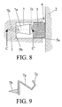
- figure 8 is a diagrammatic view in lateral section corresponding to figure 6, presenting a second embodiment of the spring element;
- figure 9 is a diagrammatic view in lateral section through the line C-C' marked in figure 8, according to the second embodiment of the spring element in which the attachment of that spring element to the back wall is carried out by means of a piercing body;
- figure 10 is a diagrammatic view in lateral section corresponding to figure 7, presenting the second embodiment of the spring element shown in figures 8 and 9;
- figure 11A is a diagrammatic view in lateral section through the line D-D' marked in figure 10, of the spring element, according to a second embodiment in which the attachment of the strip to the back wall is carried out by means of a piercing body;
- figure 11B is a diagrammatic view in lateral section through the line D-D' marked in figure 10, of the spring element, according to a second embodiment of the spring element in which the attachment of the strip to the back wall is carried out by means of a threaded body;
- figure 12 is a lateral perspective view of a model of an elevator and the arrangement of the spring elements therein;
- figure 13 is a partially sectioned front perspective view of the elevator with the sealing element introduced;
- figure 14 is a partially sectioned perspective view of a model of an aircraft tail in which the elevator shown in figures 12 and 13 is fitted.
- Appearing in these figures are numerical references denoting the following elements:
- 1 first piece
- 2 second piece
- 3 packing body
- 4 space to seal
- 5 recess
- 5a front end of the recess
- 5b back wall of the recess
- 6 coil spring
- 6a piercing body
- 6b threaded body
- 7 strip
- 7a elastic section
- 7b piercing projection
- 7c support section
- 7d threaded projection
- Figures 1 and 2 show a general arrangement of the invention, in which between a
first piece 1, which remains fixed, and asecond piece 2, whose position can be varied in different tests, there exists aspace 4 which is sealed with apacking body 3. - Said packing
body 3 is manufactured from a flexible material, such as for example rubber or resin, in order to be able to adapt itself to the change in shape of the space that is produced when the second movingpiece 2 changes its position. In this way, the sealing keeps the space closed even though the latter changes shape or size owing to the movement of the pieces. - The time for changing one test arrangement for another when a space has to be sealed in different positions for testing is thus successfully reduced. In this way, it is not necessary to redo the sealing for each position to be tested since the seal adapts itself to the different shapes and sizes of the space. Because of all this, there is an evident saving in labour, work time and raw materials, which reduces the testing costs.
- In order to get this seal to adapt itself to the shape of the space, the packing
body 3 fits into arecess 5 made in the first orsecond piece packing body 3 emerges from the front end of therecess 5a. Figures 2 and 3 show a first embodiment of therecess 5, in which saidrecess 5 is made in thefirst piece 1, which is the fixed piece of the model. - In that embodiment, located in the back wall of the
recess 5b, which is opposite to thefront side 5a, are somespring elements packing element 3 against the surface of thesecond piece 2 of the model. In this way, thepacking element 3 is at all times in contact with the surface of thesecond piece 2 keeping thespace 4 closed. Moreover, thesespring elements space 4, and thepacking element 3 can also be used for different arrangements of thepieces space 4 at least partially packed. - In order to exert the function of pushing on the packing element against the surface of the piece, different spring elements can be used. In a first embodiment of these spring elements, they consist of an array of
coil springs 6, as can be seen in figures 3-7, 12-13. These coil springs 6 are attached to thefirst piece 1 in theback wall 5b of therecess 5 and they push thepacking element 3 against the surface of thesecond piece 2, keeping thespace 4 sealed. - The advantage of this embodiment is the possibility of being able to adjust the width of the spring to the size of the gap of the
recess 5. This provides greater stability in the attachment of thecoil spring 6 to the interior of therecess 5, along with less possibility of the latter becoming displaced due to possible relative movements between thefirst piece 1 and thesecond piece 2. Moreover, as there exists a greater contour in the support surface of thecoil spring 6 against thepacking element 3, theseal 4 of thespace 5 existing between thefirst piece 1 and thesecond piece 2 will be more effective. - A second embodiment of the spring elements is illustrated in figures 8-11 B. The
coil spring 6 is replaced by anelastic strip 7. Saidelastic strip 7 possesses anelastic section 7a which exerts pressure on thepacking body 3 via asupport section 7c. The advantage of using anelastic strip 7 in the invention, rather than acoil spring 6, is the greater simplicity of manufacture when dealing with very small sizes. - These
spring elements coil spring 6 and thestrip 7, must be attached to the back wall of therecess 5b, for which different attachment methods can be used. - Figures 4, 6 and 7 show a first embodiment of those means of attachment for the
coil spring 6, in which a piercingbody 6a is used, which is nailed to theback wall 5b, being retained therein. The advantage of this embodiment is its simplicity of manufacture and assembly and, therefore, lower cost. - Figure 5 shows a second embodiment of the attachment applied to the
coil spring 6, in which a threadedbody 6b, is used which is screwed to theback wall 5b and retained therein. The advantage of this second embodiment is that the attachment is firmer and more secure, which avoids possible damage to theback wall 5b which could be occasioned in the case of using the piercingbody 6a and the latter is nailed too far into the back wall. - Figures 8, 9, 10 and 11A show a first embodiment of the means of attachment applied to the
elastic strip 7 in which a piercingprojection 7b is used. Said piercingprojection 7b is nailed into theback wall 5b, being retained therein. The same advantages of simplicity of manufacture and assembly as were obtained with the attachment arrangement with a piercingbody 6a for thecoil spring 6 are obtained in with this attachment arrangement with a piercingprojection 7b for theelastic strip 7. - Figure 11B shows a second embodiment of the means of attachment applied to the
elastic strip 7 in which a threadedprojection 7d is used. Said threadedprojection 7d is screwed to theback wall 5b being retained therein and achieving an attachment that presents the same advantages of firmness and security as those offered by the embodiment by means ofcoil spring 6 and threadedbody 6b. - The
attachment elements spring elements coil spring 6 and its attachment elements, whether these be the piercingbody 6a or the threadedbody 6b, in such a way that thecoil spring 6 clutches the piercingbody 6a or the threadedbody 6b, thus producing the union between the two pieces. The advantage of the two-piece arrangement is the greater simplicity of manufacture and the possibility of being able to replace one of them in the event of deterioration rather than having to replace the complete unit. - In the same way, the
strip 7 and its attachment elements, whether these be the piercingprojection 7b or the threadedprojection 7d, can be made in a single piece or instead be produced in two different pieces joined by conventional means, among which is to be found soldering. In this case, the said two-piece embodiment arrangement presents greater simplicity of manufacture. - Figures 12, 13 and 14 show the specific application of the invention to an elevator in an aircraft tail, according to a second embodiment of the
recess 5, in which said recess is made in the moving piece, specifically in the elevator of the aircraft. - In the cases shown in the figures, the size of the elements of the invention is very small, and therefore they can be used for sealing spaces of the order of tenths of a millimetre, using for this springs of approximately half a millimetre in diameter.
Claims (15)
- System for sealing variable gaps for scale models tested in an aerodymamic tunnel comprising packing means (3) for at least partially packing a space (4) existing between two pieces (1, 2) of a model, characterised in that
at least a first piece (1) of said model is provided, on its side facing a second piece (2) of said model, with at least one recess (5) with a front end (5a) open and a back wall (5b);
the packing means consist of a packing body (3) made of an elastically flexible material inserted in the recess (5) with a front part which emerges from the front end (5a) of that recess (5);
fixed to the back wall (5b) of the recess is a set of spring elements (6, 7) which are at least partially compressed by the packing body (3) in such a way that they push the packing body (3) against the surface of the second piece (2) of the model. - System for sealing according to claim 1, characterised in that the spring elements comprise coil springs (6).
- System for sealing according to claim 2, characterised in that provided in each coil spring (6) is at least one piercing body (6a) which is nailed to the back wall (5b) of the recess (5).
- System for sealing according to claim 3, characterised in that the coil spring (6) clutches a section of the piercing body (6a).
- System for sealing according to claim 3, characterised in that the coil spring (6) and the piercing body (6a) are a single piece.
- System for sealing according to claim 2, characterised in that provided in each coil spring (6) is a threaded body (6b) threaded in said back wall (5b) of the recess (5).
- System for sealing according to claim 6, characterised in that the coil spring (6) clutches a section of the threaded body (6b).
- System for sealing according to claim 6, characterised in that the coil spring (6) and the threaded body (6b) are a single piece.
- System for sealing according to claim 1, characterised in that the spring elements comprise strips (7), each of which consists of at least one elastic section (7a) which rests of the packing body (3).
- System for sealing according to claim 9, characterised in that provided in each strip (7) is at least one piercing projection (7b) nailed to the back wall (5b) of the recess (5).
- System for sealing according to claim 10, characterised in that the strip (7) and the piercing projection (7b) are a single piece.
- System for sealing according to claim 9, characterised in that provided in each strip (7) is at least a threaded projection (7d) threaded in the back wall (5b) of the recess (5).
- System for sealing according to claim 12, characterised in that the strip (7) and the threaded projection (7d) are a single piece.
- System for sealing according to claim 1, characterised in that the first piece (1) provided with the recess (5) is the fixed piece of the model.
- System for sealing according to claim 1, characterised in that the first piece (1) provided with the recess (5) is the moving piece of the model.
Applications Claiming Priority (1)
| Application Number | Priority Date | Filing Date | Title |
|---|---|---|---|
| ES200502473A ES2285915B1 (en) | 2005-10-11 | 2005-10-11 | SEALING SYSTEM OF VARIABLE SLOTS FOR MACHINES TESTED IN AN AERODYNAMIC TUNNEL. |
Publications (2)
| Publication Number | Publication Date |
|---|---|
| EP1775566A2 true EP1775566A2 (en) | 2007-04-18 |
| EP1775566A3 EP1775566A3 (en) | 2010-06-30 |
Family
ID=37613915
Family Applications (1)
| Application Number | Title | Priority Date | Filing Date |
|---|---|---|---|
| EP06380213A Withdrawn EP1775566A3 (en) | 2005-10-11 | 2006-07-27 | System for sealing variable gaps for scale models tested in an aerodynamic tunnel |
Country Status (5)
| Country | Link |
|---|---|
| US (1) | US7340948B2 (en) |
| EP (1) | EP1775566A3 (en) |
| BR (1) | BRPI0603190A (en) |
| CA (1) | CA2555870A1 (en) |
| ES (1) | ES2285915B1 (en) |
Cited By (1)
| Publication number | Priority date | Publication date | Assignee | Title |
|---|---|---|---|---|
| CN114563161A (en) * | 2022-02-24 | 2022-05-31 | 中国船舶重工集团公司第七一九研究所 | Water tunnel test simulation device and method for rudder shaft system clearance |
Families Citing this family (4)
| Publication number | Priority date | Publication date | Assignee | Title |
|---|---|---|---|---|
| US7793941B2 (en) * | 2007-01-23 | 2010-09-14 | Gm Global Technology Operations, Inc. | Ring seal with inner lip |
| CN110375948B (en) * | 2019-08-16 | 2024-02-23 | 中国航空工业集团公司沈阳空气动力研究所 | Sealing device for gap between model and support |
| CN113446400B (en) * | 2021-06-28 | 2022-05-31 | 中国空气动力研究与发展中心设备设计与测试技术研究所 | Sealing system suitable for continuous wind tunnel semi-flexible wall spray pipe |
| EP4166817A1 (en) * | 2021-10-18 | 2023-04-19 | Koenigsegg Automotive AB | Shaft arrangement |
Family Cites Families (11)
| Publication number | Priority date | Publication date | Assignee | Title |
|---|---|---|---|---|
| GB1084260A (en) * | ||||
| DE1810138C3 (en) * | 1968-11-21 | 1975-01-23 | Messerschmitt-Boelkow-Blohm Gmbh, 8000 Muenchen | Airplane with wings that can be pivoted about vertical axes |
| FR2304070A1 (en) * | 1975-03-12 | 1976-10-08 | Aerospatiale | Model wing surface pressure detector - employs orifices in surface feeding tubular transmission channels within wing |
| US4372159A (en) * | 1981-06-17 | 1983-02-08 | The United States Of America As Represented By The Administrator Of The National Aeronautics And Space Administration | Aeroelastic instability stoppers for wind tunnel models |
| US4555118A (en) * | 1982-12-30 | 1985-11-26 | Mobil Oil Corporation | Seal construction for fluid swivel joints |
| US4576548A (en) * | 1984-01-17 | 1986-03-18 | Westinghouse Electric Corp. | Self-aligning static seal for gas turbine stator vanes |
| JPS60164233A (en) * | 1984-02-06 | 1985-08-27 | Kawasaki Heavy Ind Ltd | Measuring method of aerodynamic force and measuring system thereof |
| US4577579A (en) * | 1984-09-13 | 1986-03-25 | The Boeing Company | Hydrofoil seal |
| US4836035A (en) * | 1988-06-23 | 1989-06-06 | The United States Of America As Represented By The Administrator Of The National Aeronautics And Space Administration | Skin friction balance |
| FR2637650B1 (en) * | 1988-10-06 | 1990-11-16 | Alsthom Gec | DEVICES FOR REDUCING ARROWS AND STRESSES IN TURBINE DIAPHRAGMS |
| DE4210804A1 (en) * | 1992-04-01 | 1993-10-07 | Mtu Muenchen Gmbh | Device for sealing a gap between angularly offset and fixed or movably arranged wall elements |
-
2005
- 2005-10-11 ES ES200502473A patent/ES2285915B1/en not_active Expired - Fee Related
-
2006
- 2006-07-27 EP EP06380213A patent/EP1775566A3/en not_active Withdrawn
- 2006-08-02 CA CA002555870A patent/CA2555870A1/en not_active Abandoned
- 2006-08-04 US US11/499,481 patent/US7340948B2/en not_active Expired - Fee Related
- 2006-08-08 BR BRPI0603190-0A patent/BRPI0603190A/en not_active IP Right Cessation
Cited By (2)
| Publication number | Priority date | Publication date | Assignee | Title |
|---|---|---|---|---|
| CN114563161A (en) * | 2022-02-24 | 2022-05-31 | 中国船舶重工集团公司第七一九研究所 | Water tunnel test simulation device and method for rudder shaft system clearance |
| CN114563161B (en) * | 2022-02-24 | 2023-08-01 | 中国船舶重工集团公司第七一九研究所 | Water tunnel test simulation device and method for rudder shaft system gap |
Also Published As
| Publication number | Publication date |
|---|---|
| EP1775566A3 (en) | 2010-06-30 |
| BRPI0603190A (en) | 2007-08-14 |
| CA2555870A1 (en) | 2007-04-11 |
| ES2285915A1 (en) | 2007-11-16 |
| US20070085280A1 (en) | 2007-04-19 |
| US7340948B2 (en) | 2008-03-11 |
| ES2285915B1 (en) | 2008-10-16 |
Similar Documents
| Publication | Publication Date | Title |
|---|---|---|
| US8286362B2 (en) | Device for measuring seal gaps of vehicles | |
| US4441278A (en) | Mounting for endless sealing strips | |
| US3751754A (en) | Windshield wiper assembly | |
| US7340948B2 (en) | System for sealing variable gaps for scale models tested in an aerodynamic tunnel | |
| US20060220328A1 (en) | Rail car door sealing gasket | |
| US20190144015A1 (en) | Cushioning apparatus for a railway car | |
| AU2018369996B2 (en) | Selective cushioning apparatus for a railway car | |
| DE102005035183A1 (en) | Customizable mounting of a tire monitoring assembly | |
| CN103847952A (en) | Improved aircraft windshield assembly | |
| US7043977B2 (en) | Device and method for measuring parameters during flight tests of an aircraft | |
| US9933073B2 (en) | Aircraft | |
| US4507963A (en) | Tachograph cover door assembly | |
| GB1473466A (en) | Magnetic transducer head suspension assembly | |
| JP2008532830A (en) | Sealed structure | |
| CN108761125A (en) | Elastic pitot and aircraft | |
| CN207440140U (en) | A kind of pneumatic combination instrument assembly detection fixture | |
| CN113405748B (en) | Device and method for measuring deflection of cabin door of airplane | |
| CN212360501U (en) | Multi-directional opening type sliding rail structure | |
| GB1570562A (en) | Adjustable shaft mounting | |
| CN221114177U (en) | Car door sealing strip bonding mechanism and system | |
| CN221546942U (en) | Skeleton of logging instrument | |
| CN222746413U (en) | A self-locking structure of sealing nail | |
| CN219869613U (en) | Automobile sealing gap measuring device | |
| US20100314203A1 (en) | Method for the assembly of a wear indicator on a brake | |
| CN221299929U (en) | High-stability gas spring |
Legal Events
| Date | Code | Title | Description |
|---|---|---|---|
| PUAI | Public reference made under article 153(3) epc to a published international application that has entered the european phase |
Free format text: ORIGINAL CODE: 0009012 |
|
| AK | Designated contracting states |
Kind code of ref document: A2 Designated state(s): AT BE BG CH CY CZ DE DK EE ES FI FR GB GR HU IE IS IT LI LT LU LV MC NL PL PT RO SE SI SK TR |
|
| AX | Request for extension of the european patent |
Extension state: AL BA HR MK YU |
|
| RAP1 | Party data changed (applicant data changed or rights of an application transferred) |
Owner name: AIRBUS OPERATIONS S.L. |
|
| PUAL | Search report despatched |
Free format text: ORIGINAL CODE: 0009013 |
|
| AK | Designated contracting states |
Kind code of ref document: A3 Designated state(s): AT BE BG CH CY CZ DE DK EE ES FI FR GB GR HU IE IS IT LI LT LU LV MC NL PL PT RO SE SI SK TR |
|
| AX | Request for extension of the european patent |
Extension state: AL BA HR MK RS |
|
| AKY | No designation fees paid | ||
| REG | Reference to a national code |
Ref country code: DE Ref legal event code: R108 Effective date: 20110208 Ref country code: DE Ref legal event code: 8566 |
|
| STAA | Information on the status of an ep patent application or granted ep patent |
Free format text: STATUS: THE APPLICATION IS DEEMED TO BE WITHDRAWN |
|
| 18D | Application deemed to be withdrawn |
Effective date: 20101231 |