-
The present invention relates to a stroke determination device for an engine for determining operational strokes of respective cylinders to decide the fuel injection timing of fuel injection devices (injectors) in a fuel injection type, multi-cylinder four-stroke engine.
-
In a fuel injection type, multi-cylinder four-stroke engine (hereinafter called "fuel injection type, multi-cylinder engine" for short) in which respective cylinders are individually supplied with fuel by fuel injection devices, it is necessary to determine which stroke of four strokes, which are the intake stroke, the compression stroke, the combustion stroke and the exhaust stroke, each cylinder operates in for optimizing the fuel injection timing of each cylinder.
-
Therefore, there are various kinds of devices which are used as a stroke determination device for determining which stroke each cylinder operates in, and which generally have a crank angle sensor for detecting a phase (crank angle position) of a crankshaft of the engine and a cam angle sensor for detecting a phase (angular position) of a camshaft to determine stroke conditions of respective cylinders from mutual relationships between the phase of the crankshaft and the phase of the camshaft (for example, see Patent Document 1).
-
Also, in order to control an injection amount of fuel to be a proper amount, it is necessary to detect a load of the engine. Thus, there is another device which is proposed as the stroke determination device, and in which an intake pressure sensor is connected to a communicating conduit that communicates with a downstream portion of a throttle valve in a throttle body of each cylinder of the engine, and an atmospheric pressure sensor for detecting the atmospheric pressure is provided, to sample a mean pressure of the respective cylinders from the communicating conduit so as to estimate a load of the engine from the sampled mean pressure of the respective cylinders and the atmospheric pressure (for example, see Patent Document 2).
Patent Document 1:
JP-B-3244715
Patent Document 2:
JP-A-Hei 10-227252 -
However, the structure in which the camshaft has the cam angle sensor for the stroke determination needs to ensure an attaching space for the sensor and thus invites upsizing of a cylinder head and an increase in cost. Particularly, the upsizing of the cylinder head is a problem for a motorcycle whose size in a vertical direction is limited.
-
In addition, resulting from that the cam angle sensor is provided adjacent to the camshaft which is in bad surroundings such as high temperature, deterioration of durability of the sensor or deterioration of reliability thereof can be invited.
-
Further, if a new engine is designed and developed, it is not so difficult to consider installation of the cam angle sensor for detecting the phase of the camshaft. However, if an existing engine is changed to the fuel injection type, a number of alterations are required to incorporate the angle sensor. A problem of an increase in cost may also arise.
-
Therefore, an object of the present invention is to resolve the problem and to provide a stroke determination device for an engine that can contribute to making a cylinder head compact and to cost reduction and also can accurately determine strokes of respective cylinders for a long period of time.
-
This objective is solved in an inventive manner by a multi-cylinder engine comprising a stroke determination device for determining operational strokes of the cylinders with a specific intake pressure measuring sensor connected to an intake conduit of a specific cylinder of said engine for detecting a sole intake pressure, and a crank angle sensor for detecting a phase of a crankshaft of said engine, wherein a control means is configured to determine a stroke based upon the intake pressure detected by said specific intake pressure measuring sensor and the phase of the crankshaft detected by said crank angle sensor.
-
Said multi-cylinder engine may further comprise a compound intake pressure measuring sensor for detecting an average intake pressure of the intake conduits of the cylinder.
-
Likewise, the control means may be configured to estimate an atmospheric pressure from the detected pressure of the specific intake pressure measuring sensor.
-
Further, the control means may be configured to determine a load of the engine using the atmospheric pressure estimated from the detected pressure of the specific intake pressure measuring sensor and the average intake pressure detected by the compound intake pressure measuring sensor.
-
According to a further preferred embodiment, a conduit length of a first communicating conduit whose one ends are connected to the intake conduits of said respective cylinders and whose other ends merge together to be connected to said compound intake pressure measuring sensor is longer than a conduit length of a second communicating conduit whose one end is connected to the intake conduit of said specific cylinder and whose another end is connected to said specific intake pressure measuring sensor.
-
Further, said compound and specific intake pressure measuring sensors may be attached on the same sides as fuel injection devices relative to the associated intake conduits.
-
In addition, said compound and specific intake pressure measuring sensors may be attached to fuel supply conduits for supplying fuel to said fuel injection devices.
-
Moreover, said specific intake pressure measuring sensor may be connected to the intake conduit of said specific cylinder through a tuning taking section provided for taking tuning of said engine.
-
According to another preferred embodiment, the specific intake pressure measuring sensor is connected to the intake conduit of said specific cylinder through said tuning taking section positioned at an end of said engine, or wherein the specific intake pressure measuring sensor is connected to the intake conduit of said specific cylinder through a pressure taking section provided separately from said tuning taking section.
-
In the following, the present invention is explained in greater detail with respect to several embodiments thereof in conjunction with the accompanying drawings, wherein:
- FIG. 1
- is a block diagram showing a structural outline of the stroke determination device for an engine according to one embodiment,
- FIG. 2
- is a characteristic diagram of an intake pressure detected by a first intake pressure sensor and a second intake pressure sensor both shown in FIG. 1,
- FIG. 3
- is a top plan view of the engine to which the stroke determination device shown in FIG. 1 is mounted,
- FIG. 4
- is a view looked in the direction indicated by the arrow A of FIG. 3, and
- FIG. 5
- is a perspective view showing a major part of another example of an intake conduit of each cylinder of the engine shown in FIG. 4.
Description of Reference Numerals:
-
- 1: stroke determination device
- 3a, 3b, 3c, 3d: intake conduit
- 5: first communicating conduit
- 7: first intake pressure sensor
- 9: second communicating conduit
- 11: second intake pressure sensor
- 13: crankshaft
- 15: crank angle sensor
- 17: control circuit
- 21: throttle valve
- 23: injector (fuel injection device)
- 25: engine
- 27: intake port
- 28: delivery pipe (fuel supply conduit)
-
Hereunder, a stroke determination device for an engine according to an embodiment will be described in detail based upon drawings.
-
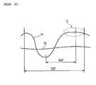
FIG. 1 is a block diagram showing a structural outline of the stroke determination device for an engine according to the one embodiment. FIG. 2 is a characteristic diagram of an intake pressure detected by a first intake pressure sensor and a second intake pressure sensor both shown in FIG. 1.
-
The stroke determination device 1 for an engine according to the embodiment is, as shown in FIG. 1, formed with a first intake pressure sensor 7 connected to intake conduits 3a, 3b, 3c, 3d of respective cylinders of a four-cylinder, four-stroke engine 25 through a first communicating conduit 5 to detect a compound intake pressure merging together, a second intake pressure sensor 11 connected to the first intake conduit 3a of a specific cylinder (first cylinder) of the engine 25 through a second communicating conduit 9 to detect a sole intake pressure, a crank angle sensor 15 for detecting a phase (crank angle position) of a crankshaft 13 of the engine 25, and a control circuit 17 for making a stroke determination of the respective cylinders of the engine 25 and estimating an atmospheric pressure based upon detection signals of the respective sensors 7, 11, 15.
-
In this embodiment, the intake conduits 3a, 3b, 3c, 3d to which the first communicating conduit 5 and the second communication conduit 9 are connected are throttle bodies incorporating throttle valves 21 which open and close respective intake flow paths in accordance with throttle operations by an operator.
-
Injectors (fuel injection devices) 23 are mounted to top sides (upper wall sides) of conduit walls positioned downstream of the throttle valves 21 in the interior of the respective intake conduits 3a, 3b, 3c, 3d to inject fuel into the intake conduits 3a, 3b, 3c, 3d.
-
The first communicating conduit 5 of the embodiment is formed with four branched conduits 5a, 5b, 5c, 5d whose one ends are connected to the respective intake conduits 3a, 3b, 3c, 3d, a collecting section 5e through which other ends of the branched conduits 5a, 5b, 5c, 5d mutually communicate with each other, and a sensor connecting conduit 5f extending from the collecting section 5e to have a distal end to which the first intake pressure sensor 7 is connected so that the first intake pressure sensor 7 communicates with the four intake conduits 3a, 3b, 3c, 3d.
-
An intake pressure of every intake conduit 3a, 3b, 3c, 3d introduced into the branched conduits 5a, 5b, 5c, 5d of the first communicating conduit 5 is detected by the first intake pressure sensor 7 as a compound pressure compounded in the collecting section 5e.
-
The second communicating conduit 9 has a single and independent conduit body, one end of which is connected to the first intake conduit 3a, and the other end of which is connected to the second intake pressure sensor 11. Accordingly, the second intake pressure sensor 11 detects a sole intake pressure of the first intake conduit 3a.
-
Connecting portions of the first communicating conduit 5 and the second communicating conduit 9 to the respective intake conduits 3a, 3b, 3c, 3d are placed on the same sides (i.e., the top sides of conduit walls) as the injectors 23.
-
Also, in the embodiment, a conduit length of the first communicating conduit 5 whose one ends are connected to the intake conduits 3a, 3b, 3c, 3d of the respective cylinders of the engine and whose other ends merge together to be connected to the first intake pressure sensor 7, even the shortest portion, is longer than a conduit length of the second communicating conduit 9.
-
In the case of the illustrated example, the first intake pressure sensor 7 is placed at a center position of the four intake conduits 3a, 3b, 3c, 3d which extend parallel to each other (the center of the in-line, four cylinder engine 25 in an axial direction of the crankshaft). Therefore, the shortest portion of the conduit length in the first communicating conduit 5 is a length of a communication route connecting either the intake conduit 3b of the second cylinder or the intake conduit 3c of the third cylinder and the first intake pressure sensor 7.
-
As indicated by an intake pressure characteristic P1 of FIG. 2, the sole intake pressure detected by the second intake pressure sensor 11 makes a change at every stroke which clearly differs from each other when four strokes such as the intake, compression, combustion and exhaust strokes made in a period wherein the crankshaft 13 rotates twice (i.e., rotation of 720 degrees) are given as one cycle. Therefore, by checking the changes with the phases of the crankshaft 13 detected by the crank angle sensor 15, the determination of the respective strokes can be made.
-
In the intake pressure characteristic P1 detected by the second intake pressure sensor 11, a portion around a position at which the exhaust stroke ends (around the area S surrounded by the dashed line of FIG. 2) is the atmospheric pressure. The atmospheric pressure thus can be estimated from the detection value of the second intake pressure sensor 11.
-
The intake pressure detected by the first intake pressure sensor 7 is a compound intake pressure, i.e., the total sum (mean pressure of the respective cylinders) of the intake pressures of the respective intake conduits 3a, 3b, 3c, 3d, and has a characteristic indicated by the intake pressure characteristic P2 of FIG. 2.
-
The control circuit 17 makes the stroke determination using the sole intake pressure of the specific cylinder (first cylinder) of the engine 25 detected by the second intake pressure sensor 11 and the phase of the crankshaft 13.
-
Also, the control circuit 17 searches injection maps using the compound intake pressure of the respective cylinders of the engine 25 detected by the first intake pressure sensor 7, and estimates a load of the engine using the atmospheric pressure estimated from the detected pressure of the second intake pressure sensor 11 and the compound intake pressure detected by the first intake pressure sensor 7.
-
According to the stroke determination device 1 for an engine discussed above, the intake pressure detected by the second intake pressure sensor 11 makes a change at every stroke which clearly differs from each other when four strokes such as the intake, compression, combustion and exhaust strokes made in a period wherein the crankshaft 13 rotates twice (i.e., rotation of 720 degrees) are given as one cycle. Therefore, it becomes practicable to make a stroke determination that is necessary for optimizing the fuel injection timing of the respective cylinders and also to estimate an atmospheric pressure that is necessary for detecting a load of the engine, using the intake pressure detected by the second intake pressure sensor 11 and the phase of the crankshaft 13 detected by the crank angle sensor 15.
-
That is, there is no need to install a cam angle sensor to the camshaft for the stroke determination nor to install an atmospheric pressure sensor for exclusive use for detecting an atmospheric pressure.
-
Accordingly, it is practicable to make the cylinder head compact and to reduce costs by disuse of the cam angle sensor for detecting the phase of the camshaft. Also, the strokes of the respective cylinders can be accurately determined for a long period of time by avoiding the deterioration of the durability of the cam angle sensor and the deterioration of the reliability thereof which are resulted from that the sensor is disposed in bad surroundings such as the high temperature. In addition, further cost reduction and downsizing can be realized by omitting the atmospheric pressure sensor for detecting the atmospheric pressure.
-
Also, in the stroke determination device 1 for an engine according to the embodiment, the conduit length of the first communicating conduit 5 is longer than that of the second communicating conduit 9. Therefore, no slack (the lowest portion) of the second communicating conduit 9 is made. Thus, there is no risk such that the fuel introduced into the intake conduit 3a accumulates in such a slack made in the second communicating conduit 9 to hinder the second intake pressure sensor 11 from accurately detecting the intake pressure.
-
That is, the second intake pressure sensor 11 in the embodiment can accurately detect the pressure change of the first intake conduit 3a shown in FIG. 2 and can output accurate pressure data that are necessary for the stroke determination and the estimation of the atmospheric pressure to the control circuit 17. In addition, a quick response of the second intake pressure sensor 11 is requited for detecting the changes of the intake pressure. In this point also, the setting such that the second communicating conduit 9 is shorter than the first communicating conduit 5 is advantageous.
-
The respective intake pressure sensors 7, 11 connected to the respective intake conduits 3a, 3b, 3c, 3d of the engine 25 need to be attached in such a manner that detecting surfaces of the sensors are directed downward in the vertical direction so that the fuel does not accumulate on the detecting surfaces of the sensors. Also, if the connecting portions connected to the respective intake conduits 3a, 3b, 3c, 3d are positioned on the bottom sides (lower wall sides) of the conduit walls of the respective intake conduits 3a, 3b, 3c, 3d, the communicating conduits can have slacks resulting from such connections.
-
However, in the embodiment, the positions of the connections of the respective intake pressure sensors 7, 11 are on the top sides (upper wall sides) of the conduit walls of the intake conduits, which are the same sides as the injectors 23. The problem discussed above can be resolved, accordingly.
-
Additionally, in the embodiment discussed above, the number of the second intake sensor 11 incorporated is one and it is connected to the first intake conduit 3a. However, according to the stroke determination device 1 for an engine of the present invention, the second intake pressure sensor 11 can be connected to any one of the other intake conduits 3b, 3c, 3d or can be connected to at least two of the intake conduits 3a, 3b, 3c, 3d to determine the stroke of the specific cylinder(s) of the engine 25.
-
FIGs. 3 and 4 illustrate the engine 25 to which the stroke determination device 1 according to the embodiment discussed above is mounted.
-
As shown in FIGs. 3 and 4, a delivery pipe (fuel supply conduit) 28 for supplying fuel to the respective injectors 23 is disposed above the intake conduits 3a, 3b, 3c, 3d connected to intake ports 27 of a cylinder head 26 in the engine 25.
-
The delivery pipe 28 extends horizontally parallel to the crankshaft direction above the respective intake conduits 3a, 3b, 3c, 3d. The delivery pipe 28 is connected to the respective injectors 23 positioned above the intake conduits 3a, 3b, 3c, 3d, and a base end side (left side in FIG. 3) of the delivery pipe is connected to a fuel supply section of a fuel tank which is not shown through a fuel pipe 30.
-
Because a pipe having certain mechanical strength is used to form the delivery pipe 28 in such an engine structure, a structure in which the first and second intake pressure sensors 7, 11 are attached to the delivery pipe 28 via brackets is applied.
-
Therefore, there is no need for special attaching members prepared to mount the first and second intake pressure sensors 7, 11. The first and second intake pressure sensors 7, 11 thus can be easily attached, and an increase in the number of parts can be avoided, resulting in a cost reduction.
-
Because the structure in which the first and second intake pressure sensors 7, 11 are attached to the delivery pipe 28 is applied, the detecting surfaces of the respective intake pressure sensors 7, 11 can be directed downward so as to be placed at the upper portions of the intake conduits 3a, 3b, 3c, 3d. A suitable mount condition that can prevent the fuel from accumulating on the detecting surfaces can be realized.
-
FIG. 5 illustrates another example of the intake conduit of each cylinder of the engine 25 in connection with the stroke determination device 1.
-
An intake conduit 33 shown in FIG. 5 has tuning taking sections 34a, 34b, 34c for taking tuning of the engine. The tuning taking sections 34a, 34b, 34c are nipple connecting sections functioning as pressure taking sections, and can be closed by plugs or the like when not used. Alternatively, connecting conduits can be screwed thereinto for connection instead of the plugs.
-
As thus constructed, when one end of the second communicating conduit 9 to which the second intake pressure sensor 11 is connected is screwed into any one of the tuning taking sections 34a, 34b, 34c for connection, the second intake pressure sensor 11 can be connected to the intake conduit 33 of the specific cylinder.
-
By employing such a structure, the connection of the second intake pressure sensor 11 and the intake conduit of the specific cylinder can be easily achieved.
-
Additionally, the second intake pressure sensor 11 is preferably connected to the intake conduit of the specific cylinder (first cylinder or fourth cylinder) through any one of the tuning taking sections 34a, 34b, 34c provided to the intake conduit of the cylinder (first cylinder or fourth cylinder) positioned at the end of the engine 25.
-
That is, because work such as connecting a T-shaped pipe to any one of the tuning taking sections 34a, 34b, 34c is necessary to take the tuning of the engine 25, any one of the tuning taking sections 34a, 34b, 34c provided to the intake conduit positioned at the end of the engine 25 can provide good workability.
-
Alternatively, the second intake pressure sensor 11 can be connected to a pressure taking section provided to the intake conduit of the specific cylinder of the engine 25 other than those of the tuning taking sections 34a, 34b, 34c.
-
Thereby, i.e., by providing the pressure taking sections other than the tuning taking sections positioned at the intake conduit of the specific cylinder of the engine 25, the second communicating conduit 9 connected to the second intake pressure sensor 11 does not need to be attached or detached when taking the tuning of the engine 25. The workability of tuning taking work of the engine can be improved, accordingly.
-
Additionally, needless to say, the number of cylinders of the engine to which the stroke determination device of the present embodiment is mounted is not limited to the in-line, four cylinders shown in the embodiment discussed above, and the stroke determination device can be applied to various multiple-cylinder engines having at least two cylinders.
-
Also, in the embodiment, the injectors 23 are positioned downstream of the throttle valves 21 of the respective intake conduits 3a, 3b, 3c, 3d. Alternatively, however, the stroke determination device for an engine according to the present embodiment can have the injectors positioned upstream of the throttle valves.
-
The description above discloses (amongst others) a preferred embodiment (first embodiment) of a stroke determination device for an engine including a first intake pressure sensor connected to intake conduits of respective cylinders of a multi-cylinder four-stroke engine for detecting a compound intake pressure merging together, a second intake pressure sensor connected to an intake conduit of a specific cylinder of the engine for detecting a sole intake pressure, and a crank angle sensor for detecting a phase of a crankshaft of the engine, wherein a stroke determination is made based upon the intake pressure detected by the second intake pressure sensor and the phase of the crankshaft detected by the crank angle sensor.
-
In the stroke determination device for an engine constructed as described above, according to the above embodiment, it is preferable that a conduit length of a first communicating conduit whose one ends are connected to the intake conduits of the respective cylinders and whose other ends merge together to be connected to the first intake pressure sensor is longer than a conduit length of a second communicating conduit whose one end is connected to the intake conduit of the specific cylinder and whose another end is connected to the second intake pressure sensor.
-
In the stroke determination device for an engine, according to the above embodiments, it is preferable that the first and second intake pressure sensors are attached on the same sides as fuel injection devices relative to the associated intake conduits.
-
In the stroke determination device for an engine, according to the above embodiments, it is preferable that the first and second intake pressure sensors are attached to fuel supply conduits for supplying fuel to the fuel injection devices.
-
In the stroke determination device for an engine, according to the above embodiments, it is preferable that the second intake pressure sensor is connected to the intake conduit of the specific cylinder through a tuning taking section provided for taking tuning of the engine.
-
In the stroke determination device for an engine, according to the above embodiments, it is preferable that the second intake pressure sensor is connected to the intake conduit of the specific cylinder through the tuning taking section positioned at an end of the engine.
-
In the stroke determination device for an engine, according to the above embodiments, it is preferable that the second intake pressure sensor is connected to the intake conduit of the specific cylinder through a pressure taking section provided separately from the tuning taking section.
-
According to the stroke determination device for an engine of the present embodiments, the sole intake pressure in the specific cylinder which is detected by the second intake pressure sensor makes a change at every stroke which clearly differs from each other when four strokes such as the intake, compression, combustion and exhaust strokes made in a period wherein the crankshaft rotates twice (i.e., rotation of 720 degrees) are given as one cycle. Therefore, it becomes practicable to make a stroke determination that is necessary for optimizing the fuel injection timing of the respective cylinders and also to estimate an atmospheric pressure that is necessary for detecting a load of the engine, using the intake pressure detected by the second intake pressure sensor and the phase of the crankshaft detected by the crank angle sensor.
-
That is, there is no need to install a cam angle sensor to the camshaft for the stroke determination nor to install an atmospheric pressure sensor for exclusive use for detecting an atmospheric pressure.
-
Accordingly, it is practicable to make the cylinder head compact and to reduce costs by disuse of the cam angle sensor for detecting the phase of the camshaft. Also, the strokes of the respective cylinders can be accurately determined for a long period of time by avoiding the deterioration of the durability of the cam angle sensor and the deterioration of the reliability thereof which are resulted from that the sensor is disposed in bad surroundings such as the high temperature. In addition, further cost reduction and downsizing can be realized by omitting the atmospheric pressure sensor for detecting the atmospheric pressure.
-
The description above further discloses, according to a preferred first aspect, a stroke determination device for an engine comprising: a first intake pressure sensor connected to intake conduits of respective cylinders of multi-cylinder four-stroke engine for detecting a compound intake pressure merging together; a second intake pressure sensor connected to an intake conduit of a specific cylinder of said engine for detecting a sole intake pressure; and a crank angle sensor for detecting a phase of a crankshaft of said engine, wherein a stroke determination is made based upon the intake pressure detected by said second intake pressure sensor and the phase of the crankshaft detected by said crank angle sensor.
-
Further, according to a preferred second aspect, a conduit length of a first communicating conduit whose one ends are connected to the intake conduits of said respective cylinders and whose other ends merge together to be connected to said first intake pressure sensor is longer than a conduit length of a second communicating conduit whose one end is connected to the intake conduit of said specific cylinder and whose another end is connected to said second intake pressure sensor.
-
Further, according to a preferred third aspect, said first and second intake pressure sensors are attached on the same sides as fuel injection devices relative to the associated intake conduits.
-
Further, according to a preferred fourth aspect, said first and second intake pressure sensors are attached to fuel supply conduits for supplying fuel to said fuel injection devices.
-
Further, according to a preferred fifth aspect, said second intake pressure sensor is connected to the intake conduit of said specific cylinder through a tuning taking section provided for taking tuning of said engine.
-
Further, according to a preferred sixth aspect, the second intake pressure sensor is connected to the intake conduit of said specific cylinder through said tuning taking section positioned at an end of said engine.
-
Further, according to a preferred seventh aspect, the second intake pressure sensor is connected to the intake conduit of said specific cylinder through a pressure taking section provided separately from said tuning taking section.
-
In addition, the description above discloses, as a particularly preferred embodiment, in order to provide a stroke determination device for an engine that can contribute to making a cylinder head compact and to cost reduction and also can accurately determine strokes of respective cylinders for a long period of time, wherein by having a first intake pressure sensor 7 connected to intake conduits 3a, 3b, 3c, 3d of respective cylinders of a four-cylinder, four-stroke engine through a first communicating conduit 5 for detecting a compound intake pressure merging together, a second intake pressure sensor 11 connected to the first intake conduit 3a of the specific cylinder of the engine 25 through a second communicating conduit 9 for detecting a sole intake pressure, and a crank angle sensor 15 for detecting a phase (crank angle position) of a crankshaft 13 of the engine 25, a stroke determination is made based upon the intake pressure detected by the second intake pressure sensor 11 and the phase of the crankshaft 13 detected by the crank angle sensor 15.