EP1775423A2 - Turbine shroud segment - Google Patents
Turbine shroud segment Download PDFInfo
- Publication number
- EP1775423A2 EP1775423A2 EP06254136A EP06254136A EP1775423A2 EP 1775423 A2 EP1775423 A2 EP 1775423A2 EP 06254136 A EP06254136 A EP 06254136A EP 06254136 A EP06254136 A EP 06254136A EP 1775423 A2 EP1775423 A2 EP 1775423A2
- Authority
- EP
- European Patent Office
- Prior art keywords
- shroud segment
- face
- shroud
- segment
- axial direction
- Prior art date
- Legal status (The legal status is an assumption and is not a legal conclusion. Google has not performed a legal analysis and makes no representation as to the accuracy of the status listed.)
- Withdrawn
Links
- 238000001816 cooling Methods 0.000 claims abstract description 37
- 239000012809 cooling fluid Substances 0.000 claims description 21
- 239000007789 gas Substances 0.000 description 30
- 238000000034 method Methods 0.000 description 11
- 238000010926 purge Methods 0.000 description 11
- 239000000567 combustion gas Substances 0.000 description 6
- 230000007423 decrease Effects 0.000 description 5
- 230000009429 distress Effects 0.000 description 5
- 239000000919 ceramic Substances 0.000 description 3
- 230000008878 coupling Effects 0.000 description 3
- 238000010168 coupling process Methods 0.000 description 3
- 238000005859 coupling reaction Methods 0.000 description 3
- 230000000712 assembly Effects 0.000 description 2
- 238000000429 assembly Methods 0.000 description 2
- 230000004323 axial length Effects 0.000 description 2
- 239000011248 coating agent Substances 0.000 description 2
- 238000000576 coating method Methods 0.000 description 2
- 238000002485 combustion reaction Methods 0.000 description 2
- 238000011144 upstream manufacturing Methods 0.000 description 2
- 238000005524 ceramic coating Methods 0.000 description 1
- 229910010293 ceramic material Inorganic materials 0.000 description 1
- 238000004901 spalling Methods 0.000 description 1
Images



Classifications
-
- F—MECHANICAL ENGINEERING; LIGHTING; HEATING; WEAPONS; BLASTING
- F01—MACHINES OR ENGINES IN GENERAL; ENGINE PLANTS IN GENERAL; STEAM ENGINES
- F01D—NON-POSITIVE DISPLACEMENT MACHINES OR ENGINES, e.g. STEAM TURBINES
- F01D11/00—Preventing or minimising internal leakage of working-fluid, e.g. between stages
- F01D11/08—Preventing or minimising internal leakage of working-fluid, e.g. between stages for sealing space between rotor blade tips and stator
- F01D11/14—Adjusting or regulating tip-clearance, i.e. distance between rotor-blade tips and stator casing
- F01D11/20—Actively adjusting tip-clearance
- F01D11/24—Actively adjusting tip-clearance by selectively cooling-heating stator or rotor components
-
- F—MECHANICAL ENGINEERING; LIGHTING; HEATING; WEAPONS; BLASTING
- F01—MACHINES OR ENGINES IN GENERAL; ENGINE PLANTS IN GENERAL; STEAM ENGINES
- F01D—NON-POSITIVE DISPLACEMENT MACHINES OR ENGINES, e.g. STEAM TURBINES
- F01D11/00—Preventing or minimising internal leakage of working-fluid, e.g. between stages
- F01D11/08—Preventing or minimising internal leakage of working-fluid, e.g. between stages for sealing space between rotor blade tips and stator
-
- F—MECHANICAL ENGINEERING; LIGHTING; HEATING; WEAPONS; BLASTING
- F05—INDEXING SCHEMES RELATING TO ENGINES OR PUMPS IN VARIOUS SUBCLASSES OF CLASSES F01-F04
- F05D—INDEXING SCHEME FOR ASPECTS RELATING TO NON-POSITIVE-DISPLACEMENT MACHINES OR ENGINES, GAS-TURBINES OR JET-PROPULSION PLANTS
- F05D2230/00—Manufacture
- F05D2230/90—Coating; Surface treatment
-
- F—MECHANICAL ENGINEERING; LIGHTING; HEATING; WEAPONS; BLASTING
- F05—INDEXING SCHEMES RELATING TO ENGINES OR PUMPS IN VARIOUS SUBCLASSES OF CLASSES F01-F04
- F05D—INDEXING SCHEME FOR ASPECTS RELATING TO NON-POSITIVE-DISPLACEMENT MACHINES OR ENGINES, GAS-TURBINES OR JET-PROPULSION PLANTS
- F05D2240/00—Components
- F05D2240/10—Stators
- F05D2240/11—Shroud seal segments
-
- F—MECHANICAL ENGINEERING; LIGHTING; HEATING; WEAPONS; BLASTING
- F05—INDEXING SCHEMES RELATING TO ENGINES OR PUMPS IN VARIOUS SUBCLASSES OF CLASSES F01-F04
- F05D—INDEXING SCHEME FOR ASPECTS RELATING TO NON-POSITIVE-DISPLACEMENT MACHINES OR ENGINES, GAS-TURBINES OR JET-PROPULSION PLANTS
- F05D2300/00—Materials; Properties thereof
- F05D2300/60—Properties or characteristics given to material by treatment or manufacturing
- F05D2300/611—Coating
Definitions
- This invention relates generally to gas turbine engines and, more particularly, to a turbine shroud assembly for gas turbine engines.
- the present invention provides a method for assembling a gas turbine engine.
- the method includes coupling a rotor assembly including a plurality of rotor blades about a rotatable main shaft of the gas turbine engine aligned in an axial direction of the gas turbine engine.
- a shroud assembly is coupled to the gas turbine engine.
- the shroud assembly includes a plurality of shroud segments circumferentially coupled about the rotor assembly such that a shroud spacing gap is formed in the axial direction between adjacent shroud segments.
- a cooling fluid source is coupled to each shroud segment such that cooling fluid is channeled through each shroud segment into a corresponding shroud spacing gap to facilitate positive purge flow through the shroud spacing gap.
- a shroud segment in another aspect, includes a first end face defined between a leading edge of the shroud segment and an opposing trailing edge of the shroud segment in an axial direction.
- the first end face is further defined between an inner radial edge of the shroud segment and an opposing outer radial edge of the shroud segment in a radial direction substantially perpendicular to the axial direction.
- a first end step is formed along at least a portion of the first end face in the axial direction and extends radially outwardly from the inner radial edge along at least a portion of the first end face in the radial direction.
- At least a portion of the first end step has a first step surface substantially parallel to and offset with respect to the first end face.
- At least one first cooling bore extends between an outer radial surface of the shroud segment and the first step surface. The at least one first cooling bore forms an opening positioned within the first step surface.
- the present invention provides a shroud assembly circumferentially positioned about a rotor assembly of a gas turbine engine.
- the shroud assembly includes a first shroud segment.
- the first shroud segment includes a first end face defined between a leading edge of the first shroud segment and an opposing trailing edge of the first shroud segment in an axial direction, and between an inner radial edge of the first shroud segment and an opposing outer radial edge of the first shroud segment in a radial direction substantially perpendicular to the axial direction.
- a first end step is formed along at least a portion of the first end face in the axial direction and extends radially outwardly from the inner radial edge along at least a portion of the first end face in the radial direction. At least a portion of the first end step has a first step surface substantially parallel to and offset with respect to the first end face. At least one first cooling bore extends between an outer radial surface of the first shroud segment and the first step surface. The at least one first cooling bore is positioned within the first step surface.
- a second shroud segment has a first end face coupled to the first end face of the first shroud segment.
- a shroud spacing gap is at least partially defined by the first end step between the first shroud segment and the second shroud segment.
- the present invention provides a turbine shroud assembly including a plurality of shroud segments coupled circumferentially about a rotor assembly within a high pressure gas turbine engine.
- the turbine shroud assembly facilitates a positive purge flow through and/or between adjacent shroud segments to prevent or limit shroud end face distress during gas turbine engine operation.
- the turbine shroud assembly may include shroud segments with or without a coating, such as a suitable ceramic coating. With shroud segments coated with a ceramic material, the turbine shroud assembly of the present invention prevents or limits ceramic spalling associated with conventional ceramic-coated shroud segments. Additionally, by providing positive purge flow through and/or between adjacent shroud segments, minor contact between adjacent shroud segments may be tolerable, which may prevent or decrease shroud leakage flow.
- shroud assembly of the present invention is likewise applicable to any combustion device including, without limitation, boilers, heaters and other turbine engines, having coated or uncoated shroud segments.
- Figure 1 is a schematic illustration of a gas turbine engine 10 including a fan assembly 12, a high pressure compressor 14, and a combustor 16.
- Gas turbine engine 10 also includes a high pressure turbine 18 and a low pressure turbine 20.
- gas turbine engine 10 is a F414 engine available from General Electric Company, Cincinnati, Ohio.
- the highly compressed air is delivered to combustor 16.
- the combustion exit gases are delivered from combustor 16 to a turbine nozzle assembly 22.
- Airflow from combustor 16 drives high pressure turbine 18 and low pressure turbine 20 coupled to a rotatable main turbine shaft 24 and exits gas turbine engine 10 through an exhaust system 26.
- the combustion gases are channeled through turbine nozzle segments 32 to high pressure turbine 18 and/or low pressure turbine 20 shown in Figure 1. More specifically, the combustion gases are channeled through turbine nozzle segments 32 to turbine rotor blades 34 which drive high pressure turbine 18 and/or low pressure turbine 20.
- a plurality of rotor blades 34 forms a high pressure compressor stage of gas turbine engine 10. Each rotor blade 34 is mounted to a rotor disk (not shown). Alternatively, rotor blades 34 may extend radially outwardly from a disk (not shown), such that a plurality of rotor blades 34 form a blisk (not shown).
- FIG. 2 is a partial sectional view of a turbine nozzle assembly 22 of gas turbine engine 10.
- a plurality of turbine nozzle segments 32 are circumferentially coupled together to form turbine nozzle assembly 22.
- Nozzle segment 32 includes a plurality of circumferentially-spaced airfoil vanes 36 coupled together by an arcuate radially outer band or platform 38, and an opposing arcuate radially inner band or platform (not shown). More specifically, in this embodiment, outer band 38 and the opposing inner band are integrally-formed with airfoil vanes 36, and each nozzle segment 32 includes two airfoil vanes 36.
- nozzle segment 32 is generally known as a doublet.
- nozzle segment 32 includes a single airfoil vane 36 and is generally known as a singlet.
- nozzle segment 32 includes more than two airfoil vanes 36.
- outer band 38 includes a front or upstream face 40, a rear or downstream face 42 and a radially inner surface 44 extending therebetween.
- Inner surface 44 defines a flow path for combustion gases to flow through turbine nozzle assembly 22.
- the combustion gases are channeled through nozzle segments 32 to high pressure turbine 18 and/or low pressure turbine 20. More specifically, the combustion gases are channeled through turbine nozzle segments 32 to turbine rotor blades 34 which drive high pressure turbine 18 and/or low pressure turbine 20.
- a turbine shroud assembly 50 extends circumferentially around a rotor assembly 33 including a plurality of rotor blades 34.
- Turbine shroud assembly 50 includes a front or upstream face 52, a rear or downstream face 54 and a radially inner surface 56 extending therebetween.
- An outer radial surface 58 generally opposes radially inner surface 56.
- Inner surface 56 defines a flow path for combustion gases to flow through high pressure turbine 18 and/or low pressure turbine 20.
- a plurality of similar or identical turbine shroud segments 60 are circumferentially coupled together to form turbine shroud assembly 50.
- a shroud spacing gap 62 is defined in the axial direction between adjacent shroud segments 60 to facilitate thermal expansion of adjacent shroud segments 60 and/or turbine shroud assembly 50 in a circumferential direction during gas turbine engine operation.
- a gap 70 is defined between turbine shroud front face 52 and turbine nozzle rear face 42. Gap 70 facilitates thermal expansion of turbine shroud assembly 50 and/or turbine nozzle assembly 22 in the axial direction.
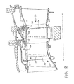
- FIGS 3 and 4 show a partial front view and a side view, respectively, of shroud segment 60.
- Shroud segment 60 includes a first end face 80 and an opposing second end face.
- the second end face is similar or identical to first end face 80, as described below.
- first end face 80 is defined between a leading edge 82 of shroud segment 60, at least partially defining front face 52 of turbine shroud assembly 50, and an opposing trailing edge 84 of shroud segment 60, at least partially defining rear face 54 of turbine shroud assembly 50, in an axial direction as shown by directional line 83 in Figure 4.
- First end face 80 is further defined between an inner radial edge 86 of shroud segment 60, at least partially defining inner surface 56 of turbine shroud assembly 50, and an opposing outer radial edge 88 of shroud segment 60, at least partially defining outer radial surface 58 of turbine shroud assembly 50, in a radial direction as shown by directional line 89 in Figure 4.
- the radial direction is substantially perpendicular to the axial direction.
- a first end step 90 is formed along at least a portion of first end face 80.
- at least a portion of first end step 90 has a first step surface 92 substantially parallel to and offset with respect to first end face 80.
- First end step 90 and/or first step surface 92 extends radially outwardly from inner radial edge 86 along at least a portion of first end face 80 in the radial direction.
- first end step 90 extends axially along first end face 80 between leading edge 82 and trailing edge 84.
- first step surface 92 extends substantially along first end face 80, i.e.
- first end step 90 defines or forms a notch or depression 96 in first end face 80, as shown in Figure 4.
- depression 96 extends along only a portion of first end face 80 in the axial direction.
- First step surface 92 surrounds an opening 98 formed by at least one first cooling bore 100 formed through shroud segment 60, as described below, and terminates radially outwardly of opening 98.
- First cooling bore 100 is configured to direct cooling fluid through shroud segment 60.
- at least one cooling bore 100 is positioned proximate leading edge 82.
- shroud segment 60 forms or includes at least one seal slot 102 for coupling adjacent shroud segments 60 together.
- shroud segment 60 includes an inner or first seal slot 102 and an outer or second seal slot 104.
- First end step 90 extends radially outwardly from inner radial edge 86 such that at least a portion of first end step 90 extends between inner radial edge 86 and inner seal slot 102.
- first end step 90 extends substantially between inner radial edge 86 and inner seal slot 102 along an axial length of first end face 80.
- first end step 90 extends along only a portion of the axial length of first end face 80 with only a portion of first end step 90 extending substantially between inner radial edge 86 and inner seal slot 102, as shown in Figure 4.
- first end step 90 forms at least a portion of shroud spacing gap 62 defined between adjacent shroud segments 60.
- first end step 90 forms shroud spacing gap 62 between adjacent, coupled shroud segments 60.
- first end step 90 forms a portion of shroud spacing gap 62 and a cooperating end step formed in adjacent, coupled shroud segment 60 forms a remaining portion of shroud spacing gap 62.
- Shroud spacing gaps 62 defined between adjacent shroud segments 60 provide positive purge flow during operating conditions to prevent or limit shroud end face distress. Further, shroud spacing gaps 62 may facilitate expansion of shroud segment 60 with respect to adjacent shroud segments 60 due to thermal conditions during operation.
- At least one cooling bore 100 provides flow communication between a suitable cooling fluid source, such as an air plenum 106, and shroud spacing gap 62 to channel cooling fluid through shroud segment 60 into corresponding shroud spacing gap 62 to facilitate positive purge flow through shroud spacing gaps 62 positioned circumferentially about rotor blades 34.
- air plenum 106 is in flow communication with high pressure compressor 14 to provide cooling fluid to turbine shroud assembly 50 and/or each shroud segment 60.
- any suitable source of cooling fluid is in flow communication with turbine shroud assembly 50 to provide cooling fluid to each shroud segment 60.
- cooling bore 100 extends between outer radial surface 58 of shroud segment 60 and first step surface 92. As shown in Figures 3 and 4, cooling bore 100 forms opening 98 positioned within first step surface 92. In this embodiment, cooling bore 100 provides flow communication between a suitable cooling fluid source, such as air plenum 106, and shroud spacing gap 62 to provide positive purge flow through shroud spacing gaps 62 positioned circumferentially about rotor blades 34.
- a suitable cooling fluid source such as air plenum 106
- shroud segment 60 includes a second end face 110 opposing first end face 80.
- second end face 110 is similar or identical to first end face 80.
- Second end face 110 is defined between leading edge 82 and trailing edge 84 in the axial direction, and between inner radial edge 86 and outer radial edge 88 in the radial direction.
- a second end step 112 is formed along at least a portion of second end face 110 in the axial direction and extends radially outwardly from inner radial edge 86 along at least a portion of second end face 110.
- At least a portion of second end step 112 has a second step surface 113 that is substantially parallel to and offset with respect to second end face 110.
- Second end step 112 at least partially defines a shroud spacing gap 62.
- At least one second cooling bore 114 extends between outer radial surface 58 and second step surface 113. Second cooling bore 114 forms an opening 116 positioned within second step surface 113 and is configured to direct cooling fluid through shroud segment 60. In a particular embodiment, at least one second cooling bore 114 is positioned proximate leading edge 82. Second cooling bore 114 provides flow communication between a cooling fluid source, such as air plenum 106, and shroud spacing gap 62 to facilitate positive purge flow through shroud spacing gaps 62 positioned circumferentially about rotor blades 34.
- a cooling fluid source such as air plenum 106
- a method for assembling gas turbine engine 10 includes coupling rotor assembly 33 about rotatable main shaft 24 of gas turbine engine 10.
- Main shaft 24 is aligned with a longitudinal axis 25 of gas turbine engine 10 in an axial direction, as shown in Figure 1.
- rotor assembly 33 includes a plurality of rotor blades 34 coupled to main shaft 24 and rotatable with main shaft 24 during operation of gas turbine engine 10.
- a shroud assembly 50 is coupled to gas turbine engine 10.
- Shroud assembly 50 includes a plurality of shroud segments 60 that are coupled and circumferentially positioned about rotor assembly 33 such that shroud spacing gap 62 is formed in the axial direction between adjacent shroud segments 60.
- first end step 90 is formed in first end face 80 of shroud segment 60 such that first end step 90 at least partially defines shroud spacing gap 62.
- At least one cooling bore 100 is formed through shroud segment 60 to extend between outer radial surface 58 of shroud segment 60 and first step surface 92. Cooling bore 100 forms opening 98 positioned within first step surface 92, as shown in Figures 3 and 4.
- a cooling fluid source is coupled to each shroud segment 60 such that cooling fluid is channeled through each shroud segment 60 into a corresponding shroud spacing gap 62 to facilitate positive purge flow through shroud spacing gap 62 during operation of gas turbine engine 10.
- at least one cooling bore 100 is formed between outer radial surface 58 of each shroud segment 60 and first step surface 92 substantially parallel to offset with respect to first end face 80 of shroud segment 60. Cooling bore 100 provides flow communication between the cooling fluid source and shroud spacing gap 62.
- shroud segment 60 includes second end face 110 opposing first end face 80.
- Second end face 110 is similar or identical to first end face 80 and is defined between leading edge 82 and trailing edge 84 in the axial direction, and between inner radial edge 86 and outer radial edge 88 in the radial direction.
- Second end step 112 is formed along at least a portion of second end face 110 in the axial direction and extends radially outwardly from inner radial edge 86 along at least a portion of second end face 110.
- Second end step 112 at least partially defines a shroud spacing gap 62.
- At least one second cooling bore 114 extends between outer radial surface 58 and second step surface 113.
- Second cooling bore 114 forms opening 116 positioned within second step surface 113 and is configured to direct cooling fluid through shroud segment 60.
- at least one second cooling bore 114 is positioned proximate leading edge 82.
- Second cooling bore 114 provides flow communication between the cooling fluid source and shroud spacing gap 62 to facilitate positive purge flow through shroud spacing gaps 62 positioned circumferentially about rotor blades 34.
- the above-described turbine shroud assembly and method for assembling a gas turbine engine allows positive purge flow between adjacent shroud segments forming the turbine shroud assembly to prevent shroud segment end face distress. More specifically, an end step is formed in the shroud segment end face and a cooling bore is formed through the shroud segment to provide flow communication between a cooling fluid source and a shroud spacing gap at least partially defined by the end step. As a result, the turbine shroud assembly provides positive purge flow at operating conditions.
- Exemplary embodiments of a turbine shroud assembly and a method for assembling a gas turbine engine are described above in detail.
- the turbine shroud assembly and the method for assembling a gas turbine engine is not limited to the specific embodiments described herein, but rather, components of the assembly and/or steps of the method may be utilized independently and separately from other components and/or steps described herein. Further, the described assembly components and/or the method steps can also be defined in, or used in combination with, other assemblies and/or methods, and are not limited to practice with only the assembly and/or method as described herein.
Landscapes
- Engineering & Computer Science (AREA)
- Mechanical Engineering (AREA)
- General Engineering & Computer Science (AREA)
- Turbine Rotor Nozzle Sealing (AREA)
Abstract
a first end face (80) defined between a leading edge (82) of said shroud segment and an opposing trailing edge (84) of said shroud segment in an axial direction (83), and between an inner radial edge (86) of said shroud segment and an opposing outer radial edge (88) of said shroud segment in a radial direction (89) substantially perpendicular to said axial direction;
a first end step (90) formed along at least a portion (94) of said first end face in said axial direction and extending radially outwardly from said inner radial edge along at least a portion of said first end face, at least a portion of said first end step having a first step surface (92) substantially parallel to and offset with respect to said first end face; and
at least one first cooling bore (100) extending between an outer radial surface (58) of said shroud segment and said first step surface, said at least one first cooling bore forming an opening (98) positioned within said first step surface.
Description
- This invention relates generally to gas turbine engines and, more particularly, to a turbine shroud assembly for gas turbine engines.
- Many conventional turbine shroud assemblies utilize cooling fluid flow across or between shroud segments to facilitate cooling of the shroud segments. During gas turbine engine operation, the shroud segments thermally expand in a circumferential direction due to exposure to high temperatures associated with the engine operation. This thermal expansion results in a decrease in spacing between adjacent shroud segments. As the spacing between adjacent shroud segments decreases, the amount of cooling fluid flow also decreases. The decrease in cooling fluid flow prevents or limits cooling of the shroud segment faces and ultimately results in shroud segment distress, particularly at the circumferential end faces of the shroud segments. Further, such shroud segment distress may result in spallation of a ceramic shroud coating.
- In one aspect, the present invention provides a method for assembling a gas turbine engine. The method includes coupling a rotor assembly including a plurality of rotor blades about a rotatable main shaft of the gas turbine engine aligned in an axial direction of the gas turbine engine. A shroud assembly is coupled to the gas turbine engine. The shroud assembly includes a plurality of shroud segments circumferentially coupled about the rotor assembly such that a shroud spacing gap is formed in the axial direction between adjacent shroud segments. A cooling fluid source is coupled to each shroud segment such that cooling fluid is channeled through each shroud segment into a corresponding shroud spacing gap to facilitate positive purge flow through the shroud spacing gap.
- In another aspect, a shroud segment is provided. The shroud segment includes a first end face defined between a leading edge of the shroud segment and an opposing trailing edge of the shroud segment in an axial direction. The first end face is further defined between an inner radial edge of the shroud segment and an opposing outer radial edge of the shroud segment in a radial direction substantially perpendicular to the axial direction. A first end step is formed along at least a portion of the first end face in the axial direction and extends radially outwardly from the inner radial edge along at least a portion of the first end face in the radial direction. At least a portion of the first end step has a first step surface substantially parallel to and offset with respect to the first end face. At least one first cooling bore extends between an outer radial surface of the shroud segment and the first step surface. The at least one first cooling bore forms an opening positioned within the first step surface.
- In another aspect, the present invention provides a shroud assembly circumferentially positioned about a rotor assembly of a gas turbine engine. The shroud assembly includes a first shroud segment. The first shroud segment includes a first end face defined between a leading edge of the first shroud segment and an opposing trailing edge of the first shroud segment in an axial direction, and between an inner radial edge of the first shroud segment and an opposing outer radial edge of the first shroud segment in a radial direction substantially perpendicular to the axial direction. A first end step is formed along at least a portion of the first end face in the axial direction and extends radially outwardly from the inner radial edge along at least a portion of the first end face in the radial direction. At least a portion of the first end step has a first step surface substantially parallel to and offset with respect to the first end face. At least one first cooling bore extends between an outer radial surface of the first shroud segment and the first step surface. The at least one first cooling bore is positioned within the first step surface. A second shroud segment has a first end face coupled to the first end face of the first shroud segment. A shroud spacing gap is at least partially defined by the first end step between the first shroud segment and the second shroud segment.
- The invention will now be described in greater detail, by way of example, with reference to the drawings, in which:-
- Figure 1 is schematic side view of a gas turbine engine, according to one embodiment of this invention;
- Figure 2 is a partial sectional view of a gas turbine engine, according to one embodiment of this invention;
- Figure 3 is a front view of a shroud segment, according to one embodiment of this invention; and
- Figure 4 is a side view of a shroud segment, according to one embodiment of this invention.
- The present invention provides a turbine shroud assembly including a plurality of shroud segments coupled circumferentially about a rotor assembly within a high pressure gas turbine engine. The turbine shroud assembly facilitates a positive purge flow through and/or between adjacent shroud segments to prevent or limit shroud end face distress during gas turbine engine operation. The turbine shroud assembly may include shroud segments with or without a coating, such as a suitable ceramic coating. With shroud segments coated with a ceramic material, the turbine shroud assembly of the present invention prevents or limits ceramic spalling associated with conventional ceramic-coated shroud segments. Additionally, by providing positive purge flow through and/or between adjacent shroud segments, minor contact between adjacent shroud segments may be tolerable, which may prevent or decrease shroud leakage flow.
- The present invention is described below in reference to its application in connection with and operation of a gas turbine engine. However, it will be obvious to those skilled in the art and guided by the teachings herein provided that the shroud assembly of the present invention is likewise applicable to any combustion device including, without limitation, boilers, heaters and other turbine engines, having coated or uncoated shroud segments.
- Figure 1 is a schematic illustration of a
gas turbine engine 10 including afan assembly 12, ahigh pressure compressor 14, and acombustor 16.Gas turbine engine 10 also includes ahigh pressure turbine 18 and alow pressure turbine 20. In one embodiment,gas turbine engine 10 is a F414 engine available from General Electric Company, Cincinnati, Ohio. - In operation, air flows through
fan assembly 12 and compressed air is supplied fromfan assembly 12 tohigh pressure compressor 14. The highly compressed air is delivered tocombustor 16. The combustion exit gases are delivered fromcombustor 16 to aturbine nozzle assembly 22. Airflow fromcombustor 16 driveshigh pressure turbine 18 andlow pressure turbine 20 coupled to a rotatablemain turbine shaft 24 and exitsgas turbine engine 10 through anexhaust system 26. - In one embodiment, the combustion gases are channeled through turbine nozzle segments 32 to
high pressure turbine 18 and/orlow pressure turbine 20 shown in Figure 1. More specifically, the combustion gases are channeled through turbine nozzle segments 32 toturbine rotor blades 34 which drivehigh pressure turbine 18 and/orlow pressure turbine 20. In one embodiment, a plurality ofrotor blades 34 forms a high pressure compressor stage ofgas turbine engine 10. Eachrotor blade 34 is mounted to a rotor disk (not shown). Alternatively,rotor blades 34 may extend radially outwardly from a disk (not shown), such that a plurality ofrotor blades 34 form a blisk (not shown). - Figure 2 is a partial sectional view of a
turbine nozzle assembly 22 ofgas turbine engine 10. In one embodiment, a plurality of turbine nozzle segments 32 are circumferentially coupled together to formturbine nozzle assembly 22. Nozzle segment 32 includes a plurality of circumferentially-spacedairfoil vanes 36 coupled together by an arcuate radially outer band orplatform 38, and an opposing arcuate radially inner band or platform (not shown). More specifically, in this embodiment,outer band 38 and the opposing inner band are integrally-formed withairfoil vanes 36, and each nozzle segment 32 includes twoairfoil vanes 36. In such an embodiment, nozzle segment 32 is generally known as a doublet. In an alternative embodiment, nozzle segment 32 includes asingle airfoil vane 36 and is generally known as a singlet. In yet another alternative embodiment, nozzle segment 32 includes more than twoairfoil vanes 36. - As shown in Figure 2,
outer band 38 includes a front orupstream face 40, a rear ordownstream face 42 and a radiallyinner surface 44 extending therebetween.Inner surface 44 defines a flow path for combustion gases to flow throughturbine nozzle assembly 22. In one embodiment, the combustion gases are channeled through nozzle segments 32 tohigh pressure turbine 18 and/orlow pressure turbine 20. More specifically, the combustion gases are channeled through turbine nozzle segments 32 toturbine rotor blades 34 which drivehigh pressure turbine 18 and/orlow pressure turbine 20. - A
turbine shroud assembly 50 extends circumferentially around arotor assembly 33 including a plurality ofrotor blades 34.Turbine shroud assembly 50 includes a front orupstream face 52, a rear ordownstream face 54 and a radiallyinner surface 56 extending therebetween. An outer radial surface 58 generally opposes radiallyinner surface 56.Inner surface 56 defines a flow path for combustion gases to flow throughhigh pressure turbine 18 and/orlow pressure turbine 20. In one embodiment, a plurality of similar or identicalturbine shroud segments 60 are circumferentially coupled together to formturbine shroud assembly 50. In this embodiment, ashroud spacing gap 62 is defined in the axial direction betweenadjacent shroud segments 60 to facilitate thermal expansion ofadjacent shroud segments 60 and/orturbine shroud assembly 50 in a circumferential direction during gas turbine engine operation. Further, in one embodiment, agap 70 is defined between turbineshroud front face 52 and turbine nozzlerear face 42.Gap 70 facilitates thermal expansion ofturbine shroud assembly 50 and/orturbine nozzle assembly 22 in the axial direction. - Figures 3 and 4 show a partial front view and a side view, respectively, of
shroud segment 60.Shroud segment 60 includes afirst end face 80 and an opposing second end face. In one embodiment, the second end face is similar or identical tofirst end face 80, as described below. Referring further to Figure 4,first end face 80 is defined between aleading edge 82 ofshroud segment 60, at least partially definingfront face 52 ofturbine shroud assembly 50, and an opposing trailingedge 84 ofshroud segment 60, at least partially definingrear face 54 ofturbine shroud assembly 50, in an axial direction as shown by directional line 83 in Figure 4.First end face 80 is further defined between an innerradial edge 86 ofshroud segment 60, at least partially defininginner surface 56 ofturbine shroud assembly 50, and an opposing outerradial edge 88 ofshroud segment 60, at least partially defining outer radial surface 58 ofturbine shroud assembly 50, in a radial direction as shown bydirectional line 89 in Figure 4. The radial direction is substantially perpendicular to the axial direction. - Referring to Figures 3 and 4, a
first end step 90 is formed along at least a portion offirst end face 80. In one embodiment, at least a portion offirst end step 90 has afirst step surface 92 substantially parallel to and offset with respect tofirst end face 80.First end step 90 and/orfirst step surface 92 extends radially outwardly from innerradial edge 86 along at least a portion offirst end face 80 in the radial direction. In one embodiment,first end step 90 extends axially alongfirst end face 80 between leadingedge 82 and trailingedge 84. In a particular embodiment,first step surface 92 extends substantially alongfirst end face 80, i.e. from leadingedge 82 to trailingedge 84, such thatfirst step surface 92 partially formingfirst end step 90 is circumferentially offset with respect to a radiallyouter portion 94 offirst end face 80, as shown in Figure 3. In an alternative embodiment,first end step 90 defines or forms a notch ordepression 96 infirst end face 80, as shown in Figure 4. In this embodiment,depression 96 extends along only a portion offirst end face 80 in the axial direction.First step surface 92 surrounds anopening 98 formed by at least one first cooling bore 100 formed throughshroud segment 60, as described below, and terminates radially outwardly ofopening 98. First cooling bore 100 is configured to direct cooling fluid throughshroud segment 60. In a particular embodiment, at least onecooling bore 100 is positioned proximate leadingedge 82. - As shown in Figures 3 and 4,
shroud segment 60 forms or includes at least oneseal slot 102 for couplingadjacent shroud segments 60 together. In one embodiment,shroud segment 60 includes an inner orfirst seal slot 102 and an outer orsecond seal slot 104.First end step 90 extends radially outwardly from innerradial edge 86 such that at least a portion offirst end step 90 extends between innerradial edge 86 andinner seal slot 102. Referring to Figure 3, in a particular embodiment,first end step 90 extends substantially between innerradial edge 86 andinner seal slot 102 along an axial length offirst end face 80. In an alternative embodiment,first end step 90 extends along only a portion of the axial length offirst end face 80 with only a portion offirst end step 90 extending substantially between innerradial edge 86 andinner seal slot 102, as shown in Figure 4. - With the plurality of
turbine shroud segments 60 circumferentially coupled to formturbine shroud assembly 50,first end step 90 forms at least a portion ofshroud spacing gap 62 defined betweenadjacent shroud segments 60. In one embodiment,first end step 90 formsshroud spacing gap 62 between adjacent, coupledshroud segments 60. In an alternative embodiment,first end step 90 forms a portion ofshroud spacing gap 62 and a cooperating end step formed in adjacent, coupledshroud segment 60 forms a remaining portion ofshroud spacing gap 62.Shroud spacing gaps 62 defined betweenadjacent shroud segments 60 provide positive purge flow during operating conditions to prevent or limit shroud end face distress. Further,shroud spacing gaps 62 may facilitate expansion ofshroud segment 60 with respect toadjacent shroud segments 60 due to thermal conditions during operation. - As shown in Figures 3 and 4, at least one
cooling bore 100 provides flow communication between a suitable cooling fluid source, such as anair plenum 106, andshroud spacing gap 62 to channel cooling fluid throughshroud segment 60 into correspondingshroud spacing gap 62 to facilitate positive purge flow throughshroud spacing gaps 62 positioned circumferentially aboutrotor blades 34. In one embodiment,air plenum 106 is in flow communication withhigh pressure compressor 14 to provide cooling fluid toturbine shroud assembly 50 and/or eachshroud segment 60. In alternative embodiments, any suitable source of cooling fluid is in flow communication withturbine shroud assembly 50 to provide cooling fluid to eachshroud segment 60. - In one embodiment, cooling bore 100 extends between outer radial surface 58 of
shroud segment 60 andfirst step surface 92. As shown in Figures 3 and 4, cooling bore 100 forms opening 98 positioned withinfirst step surface 92. In this embodiment, cooling bore 100 provides flow communication between a suitable cooling fluid source, such asair plenum 106, andshroud spacing gap 62 to provide positive purge flow throughshroud spacing gaps 62 positioned circumferentially aboutrotor blades 34. - In one embodiment,
shroud segment 60 includes asecond end face 110 opposingfirst end face 80. In this embodiment,second end face 110 is similar or identical tofirst end face 80.Second end face 110 is defined between leadingedge 82 and trailingedge 84 in the axial direction, and between innerradial edge 86 and outerradial edge 88 in the radial direction. Asecond end step 112 is formed along at least a portion ofsecond end face 110 in the axial direction and extends radially outwardly from innerradial edge 86 along at least a portion ofsecond end face 110. At least a portion ofsecond end step 112 has asecond step surface 113 that is substantially parallel to and offset with respect tosecond end face 110.Second end step 112 at least partially defines ashroud spacing gap 62. - At least one second cooling bore 114 extends between outer radial surface 58 and
second step surface 113. Second cooling bore 114 forms anopening 116 positioned withinsecond step surface 113 and is configured to direct cooling fluid throughshroud segment 60. In a particular embodiment, at least one second cooling bore 114 is positioned proximate leadingedge 82. Second cooling bore 114 provides flow communication between a cooling fluid source, such asair plenum 106, andshroud spacing gap 62 to facilitate positive purge flow throughshroud spacing gaps 62 positioned circumferentially aboutrotor blades 34. - In one embodiment, a method for assembling
gas turbine engine 10 is provided. The method includescoupling rotor assembly 33 about rotatablemain shaft 24 ofgas turbine engine 10.Main shaft 24 is aligned with alongitudinal axis 25 ofgas turbine engine 10 in an axial direction, as shown in Figure 1. In this embodiment,rotor assembly 33 includes a plurality ofrotor blades 34 coupled tomain shaft 24 and rotatable withmain shaft 24 during operation ofgas turbine engine 10. - A
shroud assembly 50 is coupled togas turbine engine 10.Shroud assembly 50 includes a plurality ofshroud segments 60 that are coupled and circumferentially positioned aboutrotor assembly 33 such thatshroud spacing gap 62 is formed in the axial direction betweenadjacent shroud segments 60. In one embodiment,first end step 90 is formed infirst end face 80 ofshroud segment 60 such thatfirst end step 90 at least partially definesshroud spacing gap 62. At least onecooling bore 100 is formed throughshroud segment 60 to extend between outer radial surface 58 ofshroud segment 60 andfirst step surface 92. Cooling bore 100 forms opening 98 positioned withinfirst step surface 92, as shown in Figures 3 and 4. - A cooling fluid source is coupled to each
shroud segment 60 such that cooling fluid is channeled through eachshroud segment 60 into a correspondingshroud spacing gap 62 to facilitate positive purge flow throughshroud spacing gap 62 during operation ofgas turbine engine 10. In one embodiment, at least onecooling bore 100 is formed between outer radial surface 58 of eachshroud segment 60 andfirst step surface 92 substantially parallel to offset with respect tofirst end face 80 ofshroud segment 60. Cooling bore 100 provides flow communication between the cooling fluid source andshroud spacing gap 62. - In one embodiment,
shroud segment 60 includessecond end face 110 opposingfirst end face 80.Second end face 110 is similar or identical tofirst end face 80 and is defined between leadingedge 82 and trailingedge 84 in the axial direction, and between innerradial edge 86 and outerradial edge 88 in the radial direction.Second end step 112 is formed along at least a portion ofsecond end face 110 in the axial direction and extends radially outwardly from innerradial edge 86 along at least a portion ofsecond end face 110.Second end step 112 at least partially defines ashroud spacing gap 62. At least one second cooling bore 114 extends between outer radial surface 58 andsecond step surface 113. Second cooling bore 114 forms opening 116 positioned withinsecond step surface 113 and is configured to direct cooling fluid throughshroud segment 60. In a particular embodiment, at least one second cooling bore 114 is positioned proximate leadingedge 82. Second cooling bore 114 provides flow communication between the cooling fluid source andshroud spacing gap 62 to facilitate positive purge flow throughshroud spacing gaps 62 positioned circumferentially aboutrotor blades 34. - The above-described turbine shroud assembly and method for assembling a gas turbine engine allows positive purge flow between adjacent shroud segments forming the turbine shroud assembly to prevent shroud segment end face distress. More specifically, an end step is formed in the shroud segment end face and a cooling bore is formed through the shroud segment to provide flow communication between a cooling fluid source and a shroud spacing gap at least partially defined by the end step. As a result, the turbine shroud assembly provides positive purge flow at operating conditions.
- Exemplary embodiments of a turbine shroud assembly and a method for assembling a gas turbine engine are described above in detail. The turbine shroud assembly and the method for assembling a gas turbine engine is not limited to the specific embodiments described herein, but rather, components of the assembly and/or steps of the method may be utilized independently and separately from other components and/or steps described herein. Further, the described assembly components and/or the method steps can also be defined in, or used in combination with, other assemblies and/or methods, and are not limited to practice with only the assembly and/or method as described herein.
Claims (10)
- A shroud segment (60) comprising:a first end face (80) defined between a leading edge (82) of said shroud segment and an opposing trailing edge (84) of said shroud segment in an axial direction (83), and between an inner radial edge (86) of said shroud segment and an opposing outer radial edge (88) of said shroud segment in a radial direction (89) substantially perpendicular to said axial direction;a first end step (90) formed along at least a portion (94) of said first end face in said axial direction and extending radially outwardly from said inner radial edge along at least a portion of said first end face, at least a portion of said first end step having a first step surface (92) substantially parallel to and offset with respect to said first end face; andat least one first cooling bore (100) extending between an outer radial surface (58) of said shroud segment and said first step surface, said at least one first cooling bore forming an opening (98) positioned within said first step surface.
- A shroud segment (60) in accordance with Claim 1 further comprising:a second end face (110) opposing said first end face (80), said second end face defined between said leading edge (82) and said trailing edge (84) in said axial direction (83), and between said inner radial edge (86) and said outer radial edge (88) in said radial direction (89); anda second end step (112) formed along at least a portion of said second end face in said axial direction and extending radially outwardly from said inner radial edge along at least a portion of said second end face, at least a portion of said second end step having a second step surface (113) substantially parallel to and offset with respect to said second end face.
- A shroud segment (60) in accordance with Claim 2 further comprising at least one second cooling bore (114) extending between said outer radial surface (58) and said second step surface (113), said at least one second cooling bore forming an opening (116) positioned within said second step surface.
- A shroud segment (60) in accordance with Claim 1 wherein said first end step (90) forms at least a portion of a shroud spacing gap (62) defined between said shroud segment and an adjacent shroud segment.
- A shroud segment (60) in accordance with Claim 1 wherein said at least one first cooling bore (100) provides flow communication between an air plenum (106) and a shroud spacing gap (62) formed between said shroud segment and an adjacent shroud segment.
- A shroud segment (60) in accordance with Claim 1 wherein said first end step (90) extends axially substantially along said first end face (80) between said leading edge (82) and said trailing edge (84).
- A shroud segment (60) in accordance with Claim 1 wherein said first step surface (92) comprises a depression (96) formed on said first end face (80) and surrounding an opening (98) formed by said at least one first cooling bore (100), said depression extending partially along said first end face (80) in said axial direction (83).
- A shroud segment (60) in accordance with Claim 1 further comprising a seal slot (102) formed within said first end face (80).
- A shroud segment (60) in accordance with Claim 8 wherein said first step surface (92) extends substantially between said inner radial edge (86) and said seal slot (102).
- A shroud assembly (50) circumferentially positioned about a rotor assembly (33) of a gas turbine engine (10), said shroud assembly comprising: a first shroud segment (60) comprising:a first end face (80) defined between a leading edge (82) of said first shroud segment and an opposing trailing edge (84) of said first shroud segment in an axial direction (83), and between an inner radial edge (86) of said first shroud segment and an opposing outer radial edge (88) of said first shroud segment in a radial direction (89) substantially perpendicular to said axial direction;a first end step (90) formed along at least a portion (94) of said first end face in said axial direction and extending radially outwardly from said inner radial edge along at least a portion of said first end face, at least a portion of said first end step having a first step surface (92) substantially parallel to and offset with respect to said first end face; andat least one first cooling bore (100) extending between an outer radial surface (58) of said first shroud segment and said first step surface, said at least one first cooling bore defining an opening (98) within said first step surface;a second shroud segment having a first end face (110) coupled to said first end face of said first shroud segment; anda shroud spacing gap (62) at least partially defined by said first end step between said first shroud segment and said second shroud segment, said at lest one first cooling bore providing flow communication between a cooling fluid source and said shroud spacing gap.
Applications Claiming Priority (1)
| Application Number | Priority Date | Filing Date | Title |
|---|---|---|---|
| US11/250,660 US7377742B2 (en) | 2005-10-14 | 2005-10-14 | Turbine shroud assembly and method for assembling a gas turbine engine |
Publications (2)
| Publication Number | Publication Date |
|---|---|
| EP1775423A2 true EP1775423A2 (en) | 2007-04-18 |
| EP1775423A3 EP1775423A3 (en) | 2010-05-19 |
Family
ID=37649279
Family Applications (1)
| Application Number | Title | Priority Date | Filing Date |
|---|---|---|---|
| EP06254136A Withdrawn EP1775423A3 (en) | 2005-10-14 | 2006-08-07 | Turbine shroud segment |
Country Status (5)
| Country | Link |
|---|---|
| US (1) | US7377742B2 (en) |
| EP (1) | EP1775423A3 (en) |
| JP (1) | JP5599546B2 (en) |
| CN (1) | CN1948718B (en) |
| CA (1) | CA2555395C (en) |
Cited By (2)
| Publication number | Priority date | Publication date | Assignee | Title |
|---|---|---|---|---|
| WO2008128876A1 (en) * | 2007-04-19 | 2008-10-30 | Alstom Technology Ltd | Stator heat shield |
| FR2968350A1 (en) * | 2010-12-06 | 2012-06-08 | Snecma | SECTORIZED TURBINE RING FOR TURBOMACHINE, AND TURBOMACHINE EQUIPPED WITH SUCH A RING |
Families Citing this family (14)
| Publication number | Priority date | Publication date | Assignee | Title |
|---|---|---|---|---|
| US10337404B2 (en) * | 2010-03-08 | 2019-07-02 | General Electric Company | Preferential cooling of gas turbine nozzles |
| CN102748079B (en) * | 2012-07-17 | 2014-12-10 | 湖南航翔燃气轮机有限公司 | Turbine outer ring device |
| BR112015001969A2 (en) | 2012-07-31 | 2017-07-04 | Gen Electric | green ceramic center body, high bypass gas turbine engine and method of processing a cmc center body |
| US9238977B2 (en) | 2012-11-21 | 2016-01-19 | General Electric Company | Turbine shroud mounting and sealing arrangement |
| US9863264B2 (en) | 2012-12-10 | 2018-01-09 | General Electric Company | Turbine shroud engagement arrangement and method |
| CN103133063A (en) * | 2013-03-01 | 2013-06-05 | 哈尔滨汽轮机厂有限责任公司 | First-stage moving vane protection ring cooling mechanism for heavy medium-low calorific value gas turbine |
| US20140271142A1 (en) | 2013-03-14 | 2014-09-18 | General Electric Company | Turbine Shroud with Spline Seal |
| US10156150B2 (en) | 2013-03-14 | 2018-12-18 | United Technologies Corporation | Gas turbine engine stator vane platform cooling |
| US9249917B2 (en) * | 2013-05-14 | 2016-02-02 | General Electric Company | Active sealing member |
| US10233776B2 (en) | 2013-05-21 | 2019-03-19 | Siemens Energy, Inc. | Gas turbine ring segment cooling apparatus |
| JP6459050B2 (en) * | 2015-02-13 | 2019-01-30 | 三菱日立パワーシステムズ株式会社 | Gas turbine component, intermediate structure of gas turbine component, gas turbine, method for manufacturing gas turbine component, and method for repairing gas turbine component |
| FR3071273B1 (en) * | 2017-09-21 | 2019-08-30 | Safran Aircraft Engines | TURBINE SEALING ASSEMBLY FOR TURBOMACHINE |
| WO2019109197A1 (en) * | 2017-12-04 | 2019-06-13 | 贵州智慧能源科技有限公司 | Turbine housing |
| US10502093B2 (en) * | 2017-12-13 | 2019-12-10 | Pratt & Whitney Canada Corp. | Turbine shroud cooling |
Family Cites Families (23)
| Publication number | Priority date | Publication date | Assignee | Title |
|---|---|---|---|---|
| BE756582A (en) * | 1969-10-02 | 1971-03-01 | Gen Electric | CIRCULAR SCREEN AND SCREEN HOLDER WITH TEMPERATURE ADJUSTMENT FOR TURBOMACHINE |
| US4251185A (en) * | 1978-05-01 | 1981-02-17 | Caterpillar Tractor Co. | Expansion control ring for a turbine shroud assembly |
| US4332523A (en) * | 1979-05-25 | 1982-06-01 | Teledyne Industries, Inc. | Turbine shroud assembly |
| US4573866A (en) * | 1983-05-02 | 1986-03-04 | United Technologies Corporation | Sealed shroud for rotating body |
| US4650394A (en) * | 1984-11-13 | 1987-03-17 | United Technologies Corporation | Coolable seal assembly for a gas turbine engine |
| US4902198A (en) * | 1988-08-31 | 1990-02-20 | Westinghouse Electric Corp. | Apparatus for film cooling of turbine van shrouds |
| GB2245316B (en) * | 1990-06-21 | 1993-12-15 | Rolls Royce Plc | Improvements in shroud assemblies for turbine rotors |
| US5088888A (en) * | 1990-12-03 | 1992-02-18 | General Electric Company | Shroud seal |
| WO1994012775A1 (en) * | 1992-11-24 | 1994-06-09 | United Technologies Corporation | Coolable outer air seal assembly for a turbine |
| US5823741A (en) * | 1996-09-25 | 1998-10-20 | General Electric Co. | Cooling joint connection for abutting segments in a gas turbine engine |
| EP1022437A1 (en) * | 1999-01-19 | 2000-07-26 | Siemens Aktiengesellschaft | Construction element for use in a thermal machine |
| JP3999395B2 (en) * | 1999-03-03 | 2007-10-31 | 三菱重工業株式会社 | Gas turbine split ring |
| US6761534B1 (en) * | 1999-04-05 | 2004-07-13 | General Electric Company | Cooling circuit for a gas turbine bucket and tip shroud |
| DE19963371A1 (en) * | 1999-12-28 | 2001-07-12 | Alstom Power Schweiz Ag Baden | Chilled heat shield |
| US6354795B1 (en) * | 2000-07-27 | 2002-03-12 | General Electric Company | Shroud cooling segment and assembly |
| US6733233B2 (en) * | 2002-04-26 | 2004-05-11 | Pratt & Whitney Canada Corp. | Attachment of a ceramic shroud in a metal housing |
| US7033138B2 (en) * | 2002-09-06 | 2006-04-25 | Mitsubishi Heavy Industries, Ltd. | Ring segment of gas turbine |
| US6925814B2 (en) * | 2003-04-30 | 2005-08-09 | Pratt & Whitney Canada Corp. | Hybrid turbine tip clearance control system |
| US6848885B1 (en) * | 2003-08-18 | 2005-02-01 | General Electric Company | Methods and apparatus for fabricating gas turbine engines |
| US6942445B2 (en) * | 2003-12-04 | 2005-09-13 | Honeywell International Inc. | Gas turbine cooled shroud assembly with hot gas ingestion suppression |
| DE102004037356B4 (en) * | 2004-07-30 | 2017-11-23 | Ansaldo Energia Ip Uk Limited | Wall structure for limiting a hot gas path |
| DE102005013796A1 (en) * | 2005-03-24 | 2006-09-28 | Alstom Technology Ltd. | Heat shield |
| EP1746254B1 (en) * | 2005-07-19 | 2016-03-23 | Pratt & Whitney Canada Corp. | Apparatus and method for cooling a turbine shroud segment and vane outer shroud |
-
2005
- 2005-10-14 US US11/250,660 patent/US7377742B2/en not_active Expired - Lifetime
-
2006
- 2006-08-03 CA CA2555395A patent/CA2555395C/en not_active Expired - Fee Related
- 2006-08-07 EP EP06254136A patent/EP1775423A3/en not_active Withdrawn
- 2006-08-11 JP JP2006219430A patent/JP5599546B2/en not_active Expired - Fee Related
- 2006-08-14 CN CN2006101149502A patent/CN1948718B/en active Active
Non-Patent Citations (1)
| Title |
|---|
| None |
Cited By (3)
| Publication number | Priority date | Publication date | Assignee | Title |
|---|---|---|---|---|
| WO2008128876A1 (en) * | 2007-04-19 | 2008-10-30 | Alstom Technology Ltd | Stator heat shield |
| US7997856B2 (en) | 2007-04-19 | 2011-08-16 | Alstom Technology Ltd. | Stator heat shield |
| FR2968350A1 (en) * | 2010-12-06 | 2012-06-08 | Snecma | SECTORIZED TURBINE RING FOR TURBOMACHINE, AND TURBOMACHINE EQUIPPED WITH SUCH A RING |
Also Published As
| Publication number | Publication date |
|---|---|
| EP1775423A3 (en) | 2010-05-19 |
| CN1948718A (en) | 2007-04-18 |
| US20070086883A1 (en) | 2007-04-19 |
| JP2007107517A (en) | 2007-04-26 |
| CN1948718B (en) | 2012-08-22 |
| CA2555395A1 (en) | 2007-04-14 |
| CA2555395C (en) | 2014-12-02 |
| JP5599546B2 (en) | 2014-10-01 |
| US7377742B2 (en) | 2008-05-27 |
Similar Documents
| Publication | Publication Date | Title |
|---|---|---|
| EP3734018B1 (en) | Seal for a gas turbine engine component and corresponding method | |
| US7377742B2 (en) | Turbine shroud assembly and method for assembling a gas turbine engine | |
| US8087249B2 (en) | Turbine cooling air from a centrifugal compressor | |
| CN110017211B (en) | Turbine engine with seals | |
| US10533444B2 (en) | Turbine shroud sealing architecture | |
| US11280198B2 (en) | Turbine engine with annular cavity | |
| CN107084004B (en) | Impact holes for turbine engine components | |
| JP5491693B2 (en) | Equipment that facilitates loss reduction in turbine engines | |
| CN107023326B (en) | Manifold for use in void control system and method of manufacture | |
| CN102383863A (en) | Rotor assembly for use in gas turbine engines and method for assembling the same | |
| US20180230839A1 (en) | Turbine engine shroud assembly | |
| US20190218925A1 (en) | Turbine engine shroud | |
| US7246996B2 (en) | Methods and apparatus for maintaining rotor assembly tip clearances | |
| CN105986847A (en) | System for cooling a turbine shroud | |
| EP3557001B1 (en) | Cooling arrangement for engine components | |
| US6848885B1 (en) | Methods and apparatus for fabricating gas turbine engines | |
| CN111434894A (en) | Plug-in system for fins and method of installing the same | |
| US20190024513A1 (en) | Shield for a turbine engine airfoil | |
| EP4317649A1 (en) | Turbine airfoil with leading edge cooling passages coupled via a plenum to film cooling holes | |
| US11377963B2 (en) | Component for a turbine engine with a conduit | |
| CN114483317B (en) | Cooling structure for turbomachine component | |
| EP3015657A1 (en) | Gas turbine nozzle vane segment |
Legal Events
| Date | Code | Title | Description |
|---|---|---|---|
| PUAI | Public reference made under article 153(3) epc to a published international application that has entered the european phase |
Free format text: ORIGINAL CODE: 0009012 |
|
| AK | Designated contracting states |
Kind code of ref document: A2 Designated state(s): AT BE BG CH CY CZ DE DK EE ES FI FR GB GR HU IE IS IT LI LT LU LV MC NL PL PT RO SE SI SK TR |
|
| AX | Request for extension of the european patent |
Extension state: AL BA HR MK YU |
|
| PUAL | Search report despatched |
Free format text: ORIGINAL CODE: 0009013 |
|
| AK | Designated contracting states |
Kind code of ref document: A3 Designated state(s): AT BE BG CH CY CZ DE DK EE ES FI FR GB GR HU IE IS IT LI LT LU LV MC NL PL PT RO SE SI SK TR |
|
| AX | Request for extension of the european patent |
Extension state: AL BA HR MK RS |
|
| 17P | Request for examination filed |
Effective date: 20101119 |
|
| AKX | Designation fees paid |
Designated state(s): DE GB IT SE |
|
| 17Q | First examination report despatched |
Effective date: 20110125 |
|
| STAA | Information on the status of an ep patent application or granted ep patent |
Free format text: STATUS: THE APPLICATION IS DEEMED TO BE WITHDRAWN |
|
| 18D | Application deemed to be withdrawn |
Effective date: 20181204 |