EP1775146A1 - Tire condition monitoring device - Google Patents
Tire condition monitoring device Download PDFInfo
- Publication number
- EP1775146A1 EP1775146A1 EP06001133A EP06001133A EP1775146A1 EP 1775146 A1 EP1775146 A1 EP 1775146A1 EP 06001133 A EP06001133 A EP 06001133A EP 06001133 A EP06001133 A EP 06001133A EP 1775146 A1 EP1775146 A1 EP 1775146A1
- Authority
- EP
- European Patent Office
- Prior art keywords
- condition monitoring
- monitoring device
- tire
- tire condition
- electric circuit
- Prior art date
- Legal status (The legal status is an assumption and is not a legal conclusion. Google has not performed a legal analysis and makes no representation as to the accuracy of the status listed.)
- Granted
Links
- 238000012806 monitoring device Methods 0.000 title claims abstract description 38
- 230000011664 signaling Effects 0.000 claims abstract description 7
- 238000001514 detection method Methods 0.000 claims abstract description 5
- 239000011324 bead Substances 0.000 claims description 12
- 239000003990 capacitor Substances 0.000 claims description 7
- 238000010586 diagram Methods 0.000 description 4
- BQCADISMDOOEFD-UHFFFAOYSA-N Silver Chemical compound [Ag] BQCADISMDOOEFD-UHFFFAOYSA-N 0.000 description 3
- 229910052709 silver Inorganic materials 0.000 description 3
- 239000004332 silver Substances 0.000 description 3
- 230000001133 acceleration Effects 0.000 description 2
- 230000002411 adverse Effects 0.000 description 2
- 230000000712 assembly Effects 0.000 description 2
- 238000000429 assembly Methods 0.000 description 2
- 230000000694 effects Effects 0.000 description 2
- NQNBVCBUOCNRFZ-UHFFFAOYSA-N nickel ferrite Chemical compound [Ni]=O.O=[Fe]O[Fe]=O NQNBVCBUOCNRFZ-UHFFFAOYSA-N 0.000 description 2
- 230000002159 abnormal effect Effects 0.000 description 1
- 230000008030 elimination Effects 0.000 description 1
- 238000003379 elimination reaction Methods 0.000 description 1
- 238000005259 measurement Methods 0.000 description 1
- 239000000203 mixture Substances 0.000 description 1
- 229910000859 α-Fe Inorganic materials 0.000 description 1
Images


Classifications
-
- B—PERFORMING OPERATIONS; TRANSPORTING
- B60—VEHICLES IN GENERAL
- B60C—VEHICLE TYRES; TYRE INFLATION; TYRE CHANGING; CONNECTING VALVES TO INFLATABLE ELASTIC BODIES IN GENERAL; DEVICES OR ARRANGEMENTS RELATED TO TYRES
- B60C23/00—Devices for measuring, signalling, controlling, or distributing tyre pressure or temperature, specially adapted for mounting on vehicles; Arrangement of tyre inflating devices on vehicles, e.g. of pumps or of tanks; Tyre cooling arrangements
- B60C23/02—Signalling devices actuated by tyre pressure
- B60C23/04—Signalling devices actuated by tyre pressure mounted on the wheel or tyre
- B60C23/0408—Signalling devices actuated by tyre pressure mounted on the wheel or tyre transmitting the signals by non-mechanical means from the wheel or tyre to a vehicle body mounted receiver
- B60C23/0422—Signalling devices actuated by tyre pressure mounted on the wheel or tyre transmitting the signals by non-mechanical means from the wheel or tyre to a vehicle body mounted receiver characterised by the type of signal transmission means
- B60C23/0433—Radio signals
-
- B—PERFORMING OPERATIONS; TRANSPORTING
- B60—VEHICLES IN GENERAL
- B60C—VEHICLE TYRES; TYRE INFLATION; TYRE CHANGING; CONNECTING VALVES TO INFLATABLE ELASTIC BODIES IN GENERAL; DEVICES OR ARRANGEMENTS RELATED TO TYRES
- B60C23/00—Devices for measuring, signalling, controlling, or distributing tyre pressure or temperature, specially adapted for mounting on vehicles; Arrangement of tyre inflating devices on vehicles, e.g. of pumps or of tanks; Tyre cooling arrangements
- B60C23/02—Signalling devices actuated by tyre pressure
- B60C23/04—Signalling devices actuated by tyre pressure mounted on the wheel or tyre
- B60C23/0408—Signalling devices actuated by tyre pressure mounted on the wheel or tyre transmitting the signals by non-mechanical means from the wheel or tyre to a vehicle body mounted receiver
- B60C23/0422—Signalling devices actuated by tyre pressure mounted on the wheel or tyre transmitting the signals by non-mechanical means from the wheel or tyre to a vehicle body mounted receiver characterised by the type of signal transmission means
- B60C23/0433—Radio signals
- B60C23/0447—Wheel or tyre mounted circuits
- B60C23/0452—Antenna structure, control or arrangement
Definitions
- This invention relates to a tire condition monitoring device detecting pneumatic pressure of a tire and executing wireless signaling to transmit results of the detection to a vehicle body.
- Tire condition monitoring devices of the above-described type have conventionally been provided with an electric circuit to which electric power is supplied from a battery.
- the electric circuit includes a pressure sensor measuring pneumatic pressure of a tire. Results of measurement are transmitted to the vehicle body by radio.
- JP-A-2005-119370 discloses one of the tire condition monitoring devices of the above-described type.
- an object of the present invention is to provide a tire condition monitoring device which has higher reliability with respect to signal noise.
- the paired power lines connecting the DC power supply and the electric circuit are provided with the respective inductor elements. Consequently, noise received by the DC power supply serving as an antenna can be eliminated and accordingly, reliability with respect to signal noise can be improved as compared with the conventional tire condition monitoring devices.
- the electric circuit is mounted on one side of the circuit board so as not to be located right behind the inductor elements mounted on the other side of the circuit board. Consequently, the electric circuit can be restrained from an adverse effect of noise produced by the inductor elements.
- the inductor elements comprise a pair of chip beads respectively. Consequently, high-frequency noise can be eliminated.
- FIG. 1 A first embodiment of the present invention will be described with reference to FIGS. 1 to 4.
- a tire condition monitoring device 20 of the first embodiment is shown.
- the tire condition monitoring device 20 is provided integrally on a tire valve 50.
- Four tire condition monitoring devices 20 are fixed to four wheel assemblies 11 together with four tire valves 50 respectively though one of the wheel assemblies 11 is shown in FIG. 1.
- a tire 14 attached to each wheel assembly 11 has an inner circumferential opening closed by a rim 13 of a wheel 12, whereupon an interior of the tire 14 is closed.
- the tire valve 50 is inserted through and fixed in a through hole (not shown) formed in a widthwise middle portion of the rim 13.
- the tire valve 50 has a distal end extending from the rim 13 to the opposite side of the vehicle body 15.
- the tire condition monitoring device 20 is provided integrally on a proximal end of the tire valve 50 and disposed in the interior of the tire 14.
- the tire valve 50 includes a core in which a valve core (not shown) is provided. The valve core prevents compressed air from being discharged through the tire valve 50 and allows compressed air to be charged into the tire 14 through the tire valve 50.
- the tire condition monitoring device 20 includes a case 21 formed integrally on the proximal end of the tire valve 50.
- a circuit board 22 and a button battery 30 are provided in the case 21.
- FIG. 3 shows an electric circuit 23 mounted on the circuit board 22.
- the electric circuit 23 includes a communication controller 27 to which are connected a pressure sensor 24, a temperature sensor 25, an acceleration sensor 26 and a wireless circuit 28.
- the communication controller 27 includes a ROM, a RAM and a CPU (not shown) .
- the ROM stores data of identification numbers assigned to the tire condition monitoring devices 20 and a predetermined program.
- the tire condition monitoring device 20 is thus arranged as described above.
- a signal processor 55 as shown in FIG. 1 is provided in the vehicle body 15 so as to be capable of receiving signals from the tire condition monitoring device 20.
- the tire condition monitoring device 20 will operate as follows.
- the tire condition monitoring device 20 is deactivated when the vehicle is stopped.
- the acceleration sensor 26 is subjected to a centrifugal force due to revolution of the wheel assembly 11, thereby being activated to deliver an interrupt signal to the CPU of the communication controller 27.
- the communication controller 27 carries out the predetermined program stored on the ROM. More specifically, a pressure and a temperature in the tire 14 are detected by the pressure sensor 24 and the temperature sensor 25.
- the wireless circuit 28 periodically executes wireless signaling to transmit results of detection to the signal processor 55 together with an identification number of the tire condition monitoring device 20.
- the signal processor 55 provided in the vehicle body 15 includes a wireless circuit 56, which receives radio signals transmitted by the wireless circuit 28.
- a display 57 provided in a vehicle compartment then displays information about conditions of the tire (tire pressure and temperature or occurrence of abnormal condition).
- the tire condition monitoring device 20 can improve antinoise reliability as compared with the conventional devices.
- the electric circuit 23 is mounted separately on both sides of the circuit board 22, the circuit board 22 can be compactified.
- the electric circuit 23 is mounted on both sides of the circuit board 22 except for first portions of either one side of the circuit board 22 located right behind or corresponding to second portions of the other side of the circuit board 22 on which the choke coils 35 are mounted. Consequently, an adverse effect of electromagnetic waves radiated from the choke coils 35 can be suppressed.
- the paired power lines 31 and 32 are disposed in parallel with and close to each other as shown in FIG. 4. This arrangement of the power lines 31 and 32 renders production of normal mode noise more difficult.
- FIG. 5 illustrates a second embodiment of the invention.
- the second embodiment differs from the first embodiment in that a pair of capacitors 36 are parallel-connected between the power lines 31 and 32.
- the choke coils 35 are connected between the capacitors 36.
- the choke coils 35 and capacitors 36 constitute a normal mode choke 37. Normal mode noise transmitted to the power lines 31 and 32 can be eliminated by the normal mode choke 37.
- FIG. 6 illustrates a third embodiment of the invention.
- a pair of chip beads 38 are connected to the power lines 31 and 32, instead of the paired choke coils 36 employed in the first embodiment.
- Each chip bead 38 comprises a rectangular parallelepiped nickel ferrite member 38F and a silver electrode 38S embedded in the nickel ferrite member 38F.
- the silver electrode 38S is formed into the shape of a coil wound about a lengthwise axis of each chip bead 38.
- each chip bead 38 has both lengthwise ends provided with external electrodes 38A and 38B respectively. Both ends of the silver electrode 38S are connected to the external electrodes 38A and 38B respectively.
- the paired chip beads 38 each having a stray capacitance ranging from 0.05 to 0.2 pF are provided in the midst of the paired power lines 31 and 32. Consequently, noise whose frequency ranges from 1 to 2 GHz can be eliminated more reliably. Furthermore, the size of the tire condition monitoring device 20 can be reduced.
- the DC power supply for the electric circuit 23 should not be limited to the button battery 30.
- the DC power supply may be a cylindrically columnar battery, capacitor or the like.
- Noise may be eliminated by a ferrite ring core extending through the paired power lines 31 and 32, instead of the choke circuits 35 and the chip beads 38. Furthermore, resistors may be connected to the pair of power lines 31 and 32 for elimination of high-frequency noise.
Landscapes
- Engineering & Computer Science (AREA)
- Mechanical Engineering (AREA)
- Measuring Fluid Pressure (AREA)
Abstract
Description
- This invention relates to a tire condition monitoring device detecting pneumatic pressure of a tire and executing wireless signaling to transmit results of the detection to a vehicle body.
- Tire condition monitoring devices of the above-described type have conventionally been provided with an electric circuit to which electric power is supplied from a battery. The electric circuit includes a pressure sensor measuring pneumatic pressure of a tire. Results of measurement are transmitted to the vehicle body by radio.
JP-A-2005-119370 - Vehicles have recently been sophisticated in functionality and consequently, the necessity of tire condition monitoring devices has been increased. With increase in the necessity, the tire condition monitoring device has been required to be improved in the reliability thereof with respect to signal noise.
- Therefore, an object of the present invention is to provide a tire condition monitoring device which has higher reliability with respect to signal noise.
- The present invention provides a tire condition monitoring device including an electric circuit further including a sensor detecting pneumatic pressure of a tire and a wireless circuit executing wireless signaling to transmit results of detection by the sensor, a DC power supply supplying power to the electric circuit, and a pair of power lines connecting the DC power supply and the electric circuit to each other, the tire condition monitoring device being mounted on a wheel with the tire in a vehicle and executing wireless signaling to a vehicle body, characterized by inductor elements connected to the paired power lines respectively.
- The paired power lines connecting the DC power supply and the electric circuit are provided with the respective inductor elements. Consequently, noise received by the DC power supply serving as an antenna can be eliminated and accordingly, reliability with respect to signal noise can be improved as compared with the conventional tire condition monitoring devices.
- In one form, the tire condition monitoring device further includes a circuit board having two sides. The inductor elements are mounted on either side of the circuit board and the electric circuit is mounted on both sides of the circuit board except for portions of either one side of the circuit board right behind the inductor elements mounted on the other side of the circuit board. The paired power lines are mounted on the second portions respectively.
- The electric circuit is mounted on one side of the circuit board so as not to be located right behind the inductor elements mounted on the other side of the circuit board. Consequently, the electric circuit can be restrained from an adverse effect of noise produced by the inductor elements.
- In another form, the inductor elements comprise a pair of chip beads respectively. Consequently, high-frequency noise can be eliminated.
- The invention will be described, merely by way of example, with reference to the accompanying drawings, in which:
- FIG. 1 is a diagram of a vehicle provided with the tire condition monitoring device in accordance with a first embodiment of the present invention;
- FIG. 2 is a sectional side view of the tire condition monitoring device;
- FIG. 3 is a circuit diagram showing an electrical arrangement of the tire condition monitoring device;
- FIG. 4 is a perspective view of a button battery and a circuit board employed in the tire condition monitoring device;
- FIG. 5 is a circuit diagram showing an electrical arrangement of the tire condition monitoring device of a second embodiment in accordance with the present invention;
- FIG. 6 is a circuit diagram showing an electrical arrangement of the tire condition monitoring device of a third embodiment in accordance with the present invention; and
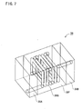
- FIG. 7 is a perspective view of chip beads.
- A first embodiment of the present invention will be described with reference to FIGS. 1 to 4. Referring to FIG. 1, a tire
condition monitoring device 20 of the first embodiment is shown. The tirecondition monitoring device 20 is provided integrally on atire valve 50. Four tirecondition monitoring devices 20 are fixed to fourwheel assemblies 11 together with fourtire valves 50 respectively though one of thewheel assemblies 11 is shown in FIG. 1. Atire 14 attached to eachwheel assembly 11 has an inner circumferential opening closed by arim 13 of awheel 12, whereupon an interior of thetire 14 is closed. - The
tire valve 50 is inserted through and fixed in a through hole (not shown) formed in a widthwise middle portion of therim 13. Thetire valve 50 has a distal end extending from therim 13 to the opposite side of thevehicle body 15. The tirecondition monitoring device 20 is provided integrally on a proximal end of thetire valve 50 and disposed in the interior of thetire 14. Thetire valve 50 includes a core in which a valve core (not shown) is provided. The valve core prevents compressed air from being discharged through thetire valve 50 and allows compressed air to be charged into thetire 14 through thetire valve 50. - Referring to FIG. 2, the tire
condition monitoring device 20 includes acase 21 formed integrally on the proximal end of thetire valve 50. Acircuit board 22 and abutton battery 30 are provided in thecase 21. FIG. 3 shows anelectric circuit 23 mounted on thecircuit board 22. Theelectric circuit 23 includes acommunication controller 27 to which are connected apressure sensor 24, atemperature sensor 25, anacceleration sensor 26 and awireless circuit 28. Thecommunication controller 27 includes a ROM, a RAM and a CPU (not shown) . The ROM stores data of identification numbers assigned to the tirecondition monitoring devices 20 and a predetermined program. - The
button battery 30 has a diameter ranging from 20 to 25 mm. Thebutton battery 30 is enclosed in a battery enclosure (not shown) provided on an inner surface of the case 21 (see FIG. 2). A pair ofpower lines positive electrode 30P and anegative electrode 30M of thebutton battery 30 respectively as shown in FIG. 4. A pair ofelectrical paths electric circuit 23 are printed on thecircuit board 22. Onepower line 31A has an end soldered to theelectrical path 31B, whereas theother power line 32A has an end soldered to theelectrical path 32B, whereby a pair ofpower lines button battery 30 to theelectric circuit 23. - Two
choke coils 35 are connected in series to theelectrical paths power lines electrical paths choke coils 35 are connected to both cut ends of theelectrical paths choke coil 35 has a pair ofterminals choke coils 35 are mounted on either one of two sides of thecircuit board 22. On the other hand, theelectric circuit 23 is mounted on both sides of thecircuit board 22 except for portions of either one side of thecircuit board 22 right behind thechoke coils 35 mounted on the other side of thecircuit board 22. In FIG. 4, regions of thecircuit board 22 on which theelectric circuit 23 is mounted are designated by symbols R1 and R2 respectively. - The tire
condition monitoring device 20 is thus arranged as described above. Asignal processor 55 as shown in FIG. 1 is provided in thevehicle body 15 so as to be capable of receiving signals from the tirecondition monitoring device 20. - The tire
condition monitoring device 20 will operate as follows. The tirecondition monitoring device 20 is deactivated when the vehicle is stopped. When the vehicle starts to run, theacceleration sensor 26 is subjected to a centrifugal force due to revolution of thewheel assembly 11, thereby being activated to deliver an interrupt signal to the CPU of thecommunication controller 27. Then, thecommunication controller 27 carries out the predetermined program stored on the ROM. More specifically, a pressure and a temperature in thetire 14 are detected by thepressure sensor 24 and thetemperature sensor 25. Thewireless circuit 28 periodically executes wireless signaling to transmit results of detection to thesignal processor 55 together with an identification number of the tirecondition monitoring device 20. Thesignal processor 55 provided in thevehicle body 15 includes awireless circuit 56, which receives radio signals transmitted by thewireless circuit 28. Adisplay 57 provided in a vehicle compartment then displays information about conditions of the tire (tire pressure and temperature or occurrence of abnormal condition). - The tire
condition monitoring device 20 inadvertently receives electromagnetic waves from a mobile telephone, a global positioning system (GPS), television or the like during running of the vehicle. Thebutton battery 30 having the diameter ranging from 20 to 25 mm could be an antenna resonating electromagnetic wave having a frequency range of 1 to 2 GHz. In the embodiment, however, bothpower lines choke coil 35 has high impedance against high-frequency noise such as frequency range of 1 to 2 GHz, whereas impedance of eachchoke coil 35 is substantially zero against DC voltage fed from thebutton battery 30. Consequently, only the noise received by thebutton battery 30 is eliminated by the choke coils 35, whereupon electric power can stably be supplied from thebutton battery 30 to theelectric circuit 23. More specifically, the tirecondition monitoring device 20 can improve antinoise reliability as compared with the conventional devices. Furthermore, since theelectric circuit 23 is mounted separately on both sides of thecircuit board 22, thecircuit board 22 can be compactified. Furthermore, theelectric circuit 23 is mounted on both sides of thecircuit board 22 except for first portions of either one side of thecircuit board 22 located right behind or corresponding to second portions of the other side of thecircuit board 22 on which the choke coils 35 are mounted. Consequently, an adverse effect of electromagnetic waves radiated from the choke coils 35 can be suppressed. Additionally, the pairedpower lines power lines - FIG. 5 illustrates a second embodiment of the invention. The second embodiment differs from the first embodiment in that a pair of
capacitors 36 are parallel-connected between thepower lines capacitors 36. The choke coils 35 andcapacitors 36 constitute anormal mode choke 37. Normal mode noise transmitted to thepower lines normal mode choke 37. - FIG. 6 illustrates a third embodiment of the invention. In the third embodiment, a pair of
chip beads 38 are connected to thepower lines chip bead 38 comprises a rectangular parallelepipednickel ferrite member 38F and asilver electrode 38S embedded in thenickel ferrite member 38F. Thesilver electrode 38S is formed into the shape of a coil wound about a lengthwise axis of eachchip bead 38. Furthermore, eachchip bead 38 has both lengthwise ends provided withexternal electrodes silver electrode 38S are connected to theexternal electrodes chip bead 38 has a stray capacitance ranging from 0.05 to 0.2 pF. Thechip beads 38 are mounted to intermediate portions of thepower lines external electrodes chip bead 38 are soldered to thepower lines - According to the third embodiment, the paired
chip beads 38 each having a stray capacitance ranging from 0.05 to 0.2 pF are provided in the midst of the pairedpower lines condition monitoring device 20 can be reduced. - The present invention should not be limited by the foregoing embodiments. The following embodiments are within the technical scope of the present invention and can be practiced. Furthermore, the invention can be practiced in various modified forms without departing from the gist.
- (1) The DC power supply for the
electric circuit 23 should not be limited to thebutton battery 30. The DC power supply may be a cylindrically columnar battery, capacitor or the like. - (2) Noise may be eliminated by a ferrite ring core extending through the paired
power lines choke circuits 35 and thechip beads 38. Furthermore, resistors may be connected to the pair ofpower lines - It is explicitly stated that all features disclosed in the description and/or the claims are intended to be disclosed separately and independently from each other for the purpose of original disclosure as well as for the purpose of restricting the claimed invention independent of the compositions of the features in the embodiments and/or the claims. It is explicitly stated that all value ranges or indications of groups of entities disclose every possible intermediate value or intermediate entity for the purpose of original disclosure as well as for the purpose of restricting the claimed invention, in particular as limits of value ranges.
Claims (5)
- A tire condition monitoring device including an electric circuit (23) further including a sensor (24, 25) detecting pneumatic pressure of a tire (14) and a wireless circuit (28) executing wireless signaling to transmit results of detection by the sensor (24, 25), a DC power supply (30) supplying power to the electric circuit (23), and a pair of power lines (31, 32) connecting the DC power supply (30) and the electric circuit (23) to each other, the tire condition monitoring device being mounted on a wheel assembly (11) with the tire (14) in a vehicle and executing wireless signaling to a vehicle body (15), characterized by inductor elements (35, 38) connected to the paired power lines (31, 32) respectively.
- The tire condition monitoring device according to claim 1, further characterized by a circuitboard (22) having two sides, and in that the inductor elements (35, 38) are mounted on either side of the circuit board and the electric circuit is mounted on both sides of the circuit board (22) except for first portions of either one side of the circuit board (22) located right behind or corresponding to second portions of the other side of the circuit board (22) on which the inductor elements (35, 38) are mounted.
- The tire condition monitoring device according to claim 1 or 2, characterized in that the inductor elements (35, 38) comprise a pair of choke coils (35) respectively.
- The tire condition monitoring device according to claim 3, further characterized by a pair of capacitors (36) connecting the paired power lines (31, 32) to each other, and in that the capacitors (36) are connected to the paired choke coils (35) so that the choke coils (35) are interposed between the capacitors (36), whereby a normal mode choke (37) is provided.
- The tire condition monitoring device according to claim 1 or 2, characterized in that the inductor elements (35, 38) comprise a pair of chip beads (38) respectively.
Applications Claiming Priority (1)
| Application Number | Priority Date | Filing Date | Title |
|---|---|---|---|
| JP2005298443A JP2007107987A (en) | 2005-10-13 | 2005-10-13 | Device for monitoring tire condition |
Publications (2)
| Publication Number | Publication Date |
|---|---|
| EP1775146A1 true EP1775146A1 (en) | 2007-04-18 |
| EP1775146B1 EP1775146B1 (en) | 2009-05-06 |
Family
ID=36097083
Family Applications (1)
| Application Number | Title | Priority Date | Filing Date |
|---|---|---|---|
| EP06001133A Expired - Lifetime EP1775146B1 (en) | 2005-10-13 | 2006-01-19 | Tire condition monitoring device |
Country Status (4)
| Country | Link |
|---|---|
| US (1) | US20070085668A1 (en) |
| EP (1) | EP1775146B1 (en) |
| JP (1) | JP2007107987A (en) |
| DE (1) | DE602006006630D1 (en) |
Families Citing this family (6)
| Publication number | Priority date | Publication date | Assignee | Title |
|---|---|---|---|---|
| US8098146B2 (en) * | 2007-10-26 | 2012-01-17 | Measurement Ltd. | Tire pressure monitoring system using wireless network |
| ATE537019T1 (en) * | 2008-04-29 | 2011-12-15 | Borgwarner Beru Systems Gmbh | METHOD, SYSTEM AND SYSTEM COMPONENTS FOR WIRELESS TIRE PRESSURE MONITORING |
| CN101863200B (en) * | 2010-06-24 | 2013-05-22 | 广东铁将军防盗设备有限公司 | Signal transmitting device with air tap tire pressure meter |
| JP5888232B2 (en) * | 2010-12-02 | 2016-03-16 | 横浜ゴム株式会社 | Tire with information acquisition device |
| US9994082B2 (en) * | 2015-07-31 | 2018-06-12 | Texas Instruments Deutschland, Gmbh | Tire monitoring based on inductive sensing |
| TWI656044B (en) * | 2018-02-27 | 2019-04-11 | 為升電裝工業股份有限公司 | Tire pressure detector with housing protection |
Citations (1)
| Publication number | Priority date | Publication date | Assignee | Title |
|---|---|---|---|---|
| US3588815A (en) * | 1968-12-03 | 1971-06-28 | Clyde Koonce | Tire pressure warning device |
Family Cites Families (23)
| Publication number | Priority date | Publication date | Assignee | Title |
|---|---|---|---|---|
| JPS6150240U (en) * | 1984-09-07 | 1986-04-04 | ||
| US4864636A (en) * | 1987-02-19 | 1989-09-05 | Brunius Robert E | Crystal controlled transmitter |
| JPH01148838U (en) * | 1988-04-06 | 1989-10-16 | ||
| US5559484A (en) * | 1991-05-14 | 1996-09-24 | Epic Technologies, Inc. | Data logging tire monitor with condition predictive capabilities and integrity checking |
| JPH06249732A (en) * | 1991-09-27 | 1994-09-09 | Toray Ind Inc | Pressure sensor |
| US5790016A (en) * | 1997-01-15 | 1998-08-04 | Algonquin Scientific, Llc | Tire pressure sensing system |
| US6124787A (en) * | 1997-01-15 | 2000-09-26 | Algonquin Scientific, Llc | Tire pressure sensing system |
| US6710708B2 (en) * | 1999-02-05 | 2004-03-23 | Schrader-Bridgeport International, Inc. | Method and apparatus for a remote tire pressure monitoring system |
| EP1081871A4 (en) * | 1999-02-24 | 2004-06-23 | Mitsubishi Electric Corp | RADIOCOMMUNICATION TERMINAL |
| JP2000332185A (en) * | 1999-05-19 | 2000-11-30 | Sony Corp | Semiconductor package |
| US6591671B2 (en) * | 1999-08-16 | 2003-07-15 | The Goodyear Tire & Rubber Company | Monitoring pneumatic tire conditions |
| BR0016544A (en) * | 1999-12-20 | 2003-02-25 | Transense Technologies Plc | Tire Condition Monitoring System |
| US6545593B2 (en) * | 2000-10-13 | 2003-04-08 | R.A. Philips Industries | AC filter for truck tractor cable circuitry |
| SE519727C2 (en) * | 2000-12-29 | 2003-04-01 | Allgon Mobile Comm Ab | Antenna device for use in at least two frequency bands |
| DE60222592T2 (en) * | 2001-02-27 | 2008-01-31 | Matsushita Electric Industrial Co., Ltd., Kadoma | Antenna switch and its use in a mobile communication device |
| US7010621B2 (en) * | 2002-02-14 | 2006-03-07 | The Boeing Company | System having a spread-spectrum clock for further suppression of electromagnetic emissions in network devices communicating via a network bus |
| US7352662B2 (en) * | 2003-06-13 | 2008-04-01 | Samsung Electronics Co., Ltd. | Molded coil device for actuator of disc drive |
| JP2005043282A (en) * | 2003-07-24 | 2005-02-17 | Pacific Ind Co Ltd | Transmitter of tire status monitor, receiver of the tire status monitor |
| JP2005119370A (en) * | 2003-10-14 | 2005-05-12 | Pacific Ind Co Ltd | Transmitter of tire condition monitoring device |
| JP2005124339A (en) * | 2003-10-17 | 2005-05-12 | Sanken Electric Co Ltd | Noise reducer and power converter |
| JP4561961B2 (en) * | 2004-01-30 | 2010-10-13 | Tdk株式会社 | Signal detection device |
| JP2006033047A (en) * | 2004-07-12 | 2006-02-02 | Pacific Ind Co Ltd | Transmitter of tire state monitor |
| US7315428B2 (en) * | 2004-10-28 | 2008-01-01 | Hewlett-Packard Development Company, L.P. | Magnetic media write signal filter |
-
2005
- 2005-10-13 JP JP2005298443A patent/JP2007107987A/en active Pending
-
2006
- 2006-01-19 DE DE602006006630T patent/DE602006006630D1/en not_active Expired - Lifetime
- 2006-01-19 US US11/335,719 patent/US20070085668A1/en not_active Abandoned
- 2006-01-19 EP EP06001133A patent/EP1775146B1/en not_active Expired - Lifetime
Patent Citations (1)
| Publication number | Priority date | Publication date | Assignee | Title |
|---|---|---|---|---|
| US3588815A (en) * | 1968-12-03 | 1971-06-28 | Clyde Koonce | Tire pressure warning device |
Also Published As
| Publication number | Publication date |
|---|---|
| DE602006006630D1 (en) | 2009-06-18 |
| JP2007107987A (en) | 2007-04-26 |
| US20070085668A1 (en) | 2007-04-19 |
| EP1775146B1 (en) | 2009-05-06 |
Similar Documents
| Publication | Publication Date | Title |
|---|---|---|
| JP6888053B2 (en) | Indicator circuit separated from the ground plane | |
| US8988207B2 (en) | Information acquiring device | |
| EP1509412B1 (en) | Capacitive pressure sensor | |
| US10071605B1 (en) | Specific multi-band antenna impedance matching circuit and tire-pressure monitoring device using same | |
| EP1976714B1 (en) | Tire monitor system having tire valve antenna | |
| US6958684B2 (en) | RF tire pressure signal sensor antenna and method of packaging | |
| CN101801692A (en) | Sensor arrangement and method for operating a sensor arrangement | |
| US20180154708A1 (en) | Tire sensor and method of manufacturing the same | |
| EP4325658A1 (en) | Tire pressure sensor and valve | |
| EP1775146B1 (en) | Tire condition monitoring device | |
| US8917211B2 (en) | Antenna and wireless IC device | |
| AU2013275529B2 (en) | Condition detection device | |
| US20170240007A1 (en) | Transmitter for Wireless Tire Pressure Monitoring System | |
| CN107078229B (en) | Battery with three electrical connection tabs | |
| JP7174415B2 (en) | RFID tag, RFID tag built-in tire, and method for adjusting resonance frequency of RFID tag | |
| US7299691B2 (en) | Sensor device for tire | |
| KR20140069587A (en) | RF module for electronic products and method for measuring RF characteristic of the RF module | |
| WO2014108990A1 (en) | Wireless microphone | |
| CN106604836B (en) | Antennas for receivers or transmitters in motor vehicles, in particular for tire condition monitoring systems | |
| JP2014187548A (en) | Radio communication equipment | |
| TWM572982U (en) | Tyre pressure monitoring system (TPMS) | |
| CN121650377A (en) | Device for detecting the pressure of a tyre, tyre tube or rim for receiving such a device, and tyre tube or rim provided with such a device | |
| JP3186286U (en) | Wireless module inspection jig | |
| JP2003165316A (en) | Tire internal pressure alarm device | |
| JP2008293331A (en) | Glass breakage detection device |
Legal Events
| Date | Code | Title | Description |
|---|---|---|---|
| PUAI | Public reference made under article 153(3) epc to a published international application that has entered the european phase |
Free format text: ORIGINAL CODE: 0009012 |
|
| AK | Designated contracting states |
Kind code of ref document: A1 Designated state(s): AT BE BG CH CY CZ DE DK EE ES FI FR GB GR HU IE IS IT LI LT LU LV MC NL PL PT RO SE SI SK TR |
|
| AX | Request for extension of the european patent |
Extension state: AL BA HR MK YU |
|
| 17P | Request for examination filed |
Effective date: 20070420 |
|
| AKX | Designation fees paid |
Designated state(s): DE FR GB |
|
| GRAP | Despatch of communication of intention to grant a patent |
Free format text: ORIGINAL CODE: EPIDOSNIGR1 |
|
| GRAS | Grant fee paid |
Free format text: ORIGINAL CODE: EPIDOSNIGR3 |
|
| GRAA | (expected) grant |
Free format text: ORIGINAL CODE: 0009210 |
|
| AK | Designated contracting states |
Kind code of ref document: B1 Designated state(s): DE FR GB |
|
| REG | Reference to a national code |
Ref country code: GB Ref legal event code: FG4D |
|
| REF | Corresponds to: |
Ref document number: 602006006630 Country of ref document: DE Date of ref document: 20090618 Kind code of ref document: P |
|
| PLBE | No opposition filed within time limit |
Free format text: ORIGINAL CODE: 0009261 |
|
| STAA | Information on the status of an ep patent application or granted ep patent |
Free format text: STATUS: NO OPPOSITION FILED WITHIN TIME LIMIT |
|
| 26N | No opposition filed |
Effective date: 20100209 |
|
| REG | Reference to a national code |
Ref country code: FR Ref legal event code: PLFP Year of fee payment: 11 |
|
| PGFP | Annual fee paid to national office [announced via postgrant information from national office to epo] |
Ref country code: FR Payment date: 20151208 Year of fee payment: 11 |
|
| PGFP | Annual fee paid to national office [announced via postgrant information from national office to epo] |
Ref country code: DE Payment date: 20160112 Year of fee payment: 11 |
|
| PGFP | Annual fee paid to national office [announced via postgrant information from national office to epo] |
Ref country code: GB Payment date: 20160113 Year of fee payment: 11 |
|
| REG | Reference to a national code |
Ref country code: DE Ref legal event code: R119 Ref document number: 602006006630 Country of ref document: DE |
|
| GBPC | Gb: european patent ceased through non-payment of renewal fee |
Effective date: 20170119 |
|
| REG | Reference to a national code |
Ref country code: FR Ref legal event code: ST Effective date: 20170929 |
|
| PG25 | Lapsed in a contracting state [announced via postgrant information from national office to epo] |
Ref country code: FR Free format text: LAPSE BECAUSE OF NON-PAYMENT OF DUE FEES Effective date: 20170131 |
|
| PG25 | Lapsed in a contracting state [announced via postgrant information from national office to epo] |
Ref country code: GB Free format text: LAPSE BECAUSE OF NON-PAYMENT OF DUE FEES Effective date: 20170119 Ref country code: DE Free format text: LAPSE BECAUSE OF NON-PAYMENT OF DUE FEES Effective date: 20170801 |