EP1775131A1 - Ink jet device with ventilation conduit - Google Patents
Ink jet device with ventilation conduit Download PDFInfo
- Publication number
- EP1775131A1 EP1775131A1 EP06122439A EP06122439A EP1775131A1 EP 1775131 A1 EP1775131 A1 EP 1775131A1 EP 06122439 A EP06122439 A EP 06122439A EP 06122439 A EP06122439 A EP 06122439A EP 1775131 A1 EP1775131 A1 EP 1775131A1
- Authority
- EP
- European Patent Office
- Prior art keywords
- ink
- channel
- ventilation
- reservoir
- jet device
- Prior art date
- Legal status (The legal status is an assumption and is not a legal conclusion. Google has not performed a legal analysis and makes no representation as to the accuracy of the status listed.)
- Granted
Links
- 238000009423 ventilation Methods 0.000 title claims abstract description 81
- 230000008018 melting Effects 0.000 claims abstract description 44
- 238000002844 melting Methods 0.000 claims abstract description 44
- 239000012943 hotmelt Substances 0.000 claims abstract description 7
- 239000007788 liquid Substances 0.000 description 5
- 239000008188 pellet Substances 0.000 description 4
- 239000004020 conductor Substances 0.000 description 2
- 238000010438 heat treatment Methods 0.000 description 2
- 230000008023 solidification Effects 0.000 description 2
- 238000007711 solidification Methods 0.000 description 2
- 238000009736 wetting Methods 0.000 description 2
- 230000001419 dependent effect Effects 0.000 description 1
- 230000000694 effects Effects 0.000 description 1
- 230000002708 enhancing effect Effects 0.000 description 1
- 239000012530 fluid Substances 0.000 description 1
- 239000000155 melt Substances 0.000 description 1
- 230000002265 prevention Effects 0.000 description 1
- 238000010926 purge Methods 0.000 description 1
- 239000007787 solid Substances 0.000 description 1
Images
Classifications
-
- B—PERFORMING OPERATIONS; TRANSPORTING
- B41—PRINTING; LINING MACHINES; TYPEWRITERS; STAMPS
- B41J—TYPEWRITERS; SELECTIVE PRINTING MECHANISMS, i.e. MECHANISMS PRINTING OTHERWISE THAN FROM A FORME; CORRECTION OF TYPOGRAPHICAL ERRORS
- B41J2/00—Typewriters or selective printing mechanisms characterised by the printing or marking process for which they are designed
- B41J2/005—Typewriters or selective printing mechanisms characterised by the printing or marking process for which they are designed characterised by bringing liquid or particles selectively into contact with a printing material
- B41J2/01—Ink jet
- B41J2/17—Ink jet characterised by ink handling
- B41J2/175—Ink supply systems ; Circuit parts therefor
- B41J2/17593—Supplying ink in a solid state
Definitions
- the invention relates to an ink jet device comprising an ink reservoir for hot melt ink, a heater arranged to heat ink contained in the ink reservoir, and a ventilation conduit which is connected at a lower end thereof to a ventilation opening in a top wall of the ink reservoir, said ventilation conduit comprising a channel a maximum diameter of which is smaller than a length of the channel.
- the channel consists of a tube.
- Ink jet printers operating with hot melt ink i.e. with ink that is solid at room temperature, comprise an ink reservoir which can be heated in order to keep the ink in the liquid state in which it can be supplied to the printhead.
- a suction to a space of the ink reservoir through a ventilation conduit.
- a negative pressure of approximately 1 kPa (10 mbar) is maintained within the space of the ink reservoir.
- ink may enter the ventilation conduit and may solidify inside the ventilation conduit, thus clogging the ventilation conduit. Under these conditions, the negative pressure can no longer be maintained in the space of the ink reservoir.
- the ventilation conduit might also be clogged in a similar manner if the ink reservoir is overfilled with melted ink.
- this object is achieved by an ink jet device of the kind mentioned above wherein said channel runs upwards through a heated area. Said channel is heated by the heated area to a temperature that is above a melting point of the ink. Thereby, any ink entering the ventilation conduit from the ink reservoir will be kept in the melted state and will flow downwards back into the ink reservoir. Thereby, clogging of the ventilation conduit is prevented.
- the channel is, through a ventilation opening, permanently opened to the ink reservoir.
- the ventilation conduit may also have a non-return valve that closes in the case of a high enough pressure within the ink reservoir.
- a height of said channel at least corresponds to a capillary rise that melted ink filling the lower end of the ventilation conduit would experience.
- the capillary rise depends on the wetting properties of the channel walls and on the geometry of the channel.
- the height of said channel preferably at least corresponds to a rise that melted ink filling the lower end of the ventilation conduit would experience due to possible capillary forces and said at least one of a negative pressure and a positive pressure.
- the height of said channel preferably at least corresponds to a rise that melted ink filling the lower end of the ventilation conduit would experience due to the negative pressure and possible capillary forces. Therefore, although the negative pressure is applied by a suction through the ventilation conduit, melted ink filling the lower end of the ventilation conduit will not rise beyond the heated area of the channel.
- At least a section of the ventilation conduit consists of a tube forming said channel and being open to the ventilation opening of the ink reservoir at the lower end of the ventilation conduit, said ventilation opening being arranged above a nominal fill level of the ink reservoir, the ventilation conduit extending substantially upright from said ventilation opening through said heated area.
- the ink jet device comprises an ink melting unit for supplying melted ink to the ink reservoir, said ink melting unit being arranged to enable melted ink to flow into the ink reservoir from above, said channel of the ventilation conduit being in thermal contact with the ink melting unit.
- the ventilation conduit runs along or through the ink melting unit and is heated by the ink melting unit.
- the heat supplied by the ink melting unit is utilized for heating the channel of the ventilation conduit.
- the ink melting unit comprises a separate heater. That is, the heater is separate from the heater arranged to heat ink contained in the ink reservoir.
- the heating of the ink reservoir and of the ink melting unit is more efficient than it would be in the case of an integrated structure with only one heater for the ink reservoir and the ink melting unit. This is because there is more energy required to melt the ink in the ink melting unit than to keep the melted ink in a melted state in the ink reservoir.
- the ventilation conduit is not guided through the melting unit but is separated therefrom such that no thermal contact exist between the ventilation conduit and the melting unit.
- a separate heater may be provided to heat at least the lower part of the ventilation conduit which communicates with the ink reservoir.
- the lower part of the ventilation conduit is the part which may be exposed to intrusion of the melted ink from the ink reservoir. This intrusion may originate from uncontrolled movement of the melted ink and/or from overfilling of the ink reservoir and/or from suction, and/or from capillary forces. Separating the ventilation conduit from the melting unit creates a greater freedom in designing the print head.
- a wall of the ink reservoir comprises an ink filter, the ink filter and the ink melting unit being arranged to enable melted ink to flow from the melting unit through the ink filter into the ink reservoir, the ventilation opening being arranged separately from the ink filter.
- a pressure sensor is arranged at the channel.
- the pressure sensor senses a pressure within the channel and can be utilized to monitor the negative pressure that is applied to the space of the ink reservoir.
- the sensor is at a position that is normally not filled with ink and, moreover, will be heated at least approximately to a determined temperature, thus enhancing the measuring accuracy.
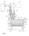
- the only figure shows a sectional view of an ink jet device with an ink reservoir and an ink melting unit.
- the ink jet device comprises an ink reservoir 10 having walls 12 made of thermally conductive material.
- an electric heater 14 is in contact with or integrated in the walls 12 of the ink reservoir so that hot melt ink 16 contained in the ink reservoir is kept at a temperature of, for example, 120°C and in any case at a temperature above its melting point, so that the ink is kept in the liquid state and is ready to be supplied to an ink jet printhead 18 which is arranged below the ink reservoir and which is in fluid connection with the ink reservoir 10 via a filter 20.
- the ink jet printhead 18 comprises printing nozzles 22, as generally known in the art. Some ink jets 24 are indicated exemplarily.
- the ink reservoir 10 and the printhead 18 may be mounted on a reciprocating carriage of a printer, so that the ink reservoir 10 is moved back and forth in the direction of the line of sight of the figure when the printer is operating.
- a top wall 26 of a compartment of the ink reservoir 10 contains an ink filter 28.
- a flat chamber 30 above the ink filter 28 is sealedly connected to a lower exit opening 32 of an ink melting unit 34 which is arranged above the ink reservoir 10.
- Walls 36 of the ink melting unit 34 are made of a thermally conductive material and form a funnel.
- At the top of the ink melting unit 34 there is arranged an inlet opening 40 for globular ink pellets 42 which consist of solidified hot melt ink. Ink pellets 42 are supplied into the interior of the ink melting unit 34 on demand.
- An electric heater 44 is in contact with or integrated in the walls 36 of the ink melting unit 34 so that an ink pellet 42 that is present in the ink melting unit 34 is melted and flows through the exit opening 32 and further through the ink filter 28 into the ink reservoir 10.
- the fill level of the ink reservoir 10 drops during printing and rises when a new ink pellet 42 is melted.
- the fill level of the ink reservoir 10 fluctuates around a nominal fill level which is below the ink filter 28 and thus below the wall 26.
- a ventilation opening 46 which is arranged separately from the ink filter 28.
- the ventilation opening 46 connects a space 48 of the ink reservoir 10 above the melted ink 16 with a tube 50 forming a section of a ventilation conduit 52. From the ventilation opening 46 at the lower end of the tube 50, the tube 50 runs substantially upright through the ink melting unit 34. In the area of the ink melting unit 34, the tube 50 forms a channel 54 which is integrated in or is in contact with the walls 36 of the ink melting unit 34 over the whole height of the ink melting unit 34. For example, the channel is integrated in a wall near the heater 44.
- the channel 54 is heated by the ink melting unit 34 to a temperature at which the ink is liquid.
- the channel 54 may run through the ink melting unit 34 at a distance from the walls 36, thus being heated by the surrounding walls 36 and/or the melted ink.
- the maximum diameter of the channel 54 is, for example, smaller than 1/10 of the length of the channel 54.
- a suction is applied to the ink reservoir 10 by a suitable suction device 56, thus maintaining a negative pressure of, for example, approximately 1 kPa (10 mbar) within the space 48 of the ink reservoir 10.
- the suction device 56 may be implemented as known in the art.
- a maximum rise level L may be, for example, approximately 90 mm above the printing nozzles 22.
- the channel 54 therefore extends to a height that is above the maximum rise level L.
- a pressure device 58 is connected to the space 48 of the ink reservoir 10 via a second conduit 60 and a second ventilation opening of the ink reservoir 10.
- the second conduit 60 is configured similar to the ventilation conduit 52 with a tube forming a section of the ventilation conduit, said tube forming a second channel running through the ink melting unit 34 in parallel with the channel 54 and being in thermal contact with the ink melting unit 34.
- the second channel lies behind the channel 54.
- the pressure device 58 is adapted to apply a pressure to the ink reservoir 10 for purging the printing nozzles 22. While the pressure is applied, the ventilation conduit 52 is closed at the suction device 56. However, ink entering the ventilation conduit 52 may be driven up the channel 54 due to the build-up of the pressure. Therefore, the height of the channel 54 is adapted to a maximum rise level L resulting from the pressure and possible capillary forces.
- the second channel of the second conduit 60 has the same height. Thus, ink entering into the ventilation conduit 52 or into the second conduit 60 will stay liquid, so that a clogging of the ventilation conduit 52 and the second conduit 60 due to solidification of the ink is prevented.
- a pressure sensor 62 for sensing the pressure within the channel 54.
- the pressure sensor 62 is indicated with dashed lines.
- the pressure device 58 may be connected to the ink reservoir via a ventilation conduit as described above, while the suction device 56 may be connected to the ink reservoir 10 in a different manner as known in the art.
- a non-return valve may be used.
- the pressure device may be connected via a non-return valve.
- the heater 44 of the ink melting unit 34 may also be arranged at a position indicated by chain dotted lines at the right side of the ink melting unit 34 in the figure instead of being arranged at the wall near the channel 54.
- the pressure device 58 may be connected to the same ventilation conduit 52 as the suction device 56 or may be integrated in the suction device 56.
Landscapes
- Ink Jet (AREA)
Abstract
Description
- The invention relates to an ink jet device comprising an ink reservoir for hot melt ink, a heater arranged to heat ink contained in the ink reservoir, and a ventilation conduit which is connected at a lower end thereof to a ventilation opening in a top wall of the ink reservoir, said ventilation conduit comprising a channel a maximum diameter of which is smaller than a length of the channel. For example, the channel consists of a tube.
- Ink jet printers operating with hot melt ink, i.e. with ink that is solid at room temperature, comprise an ink reservoir which can be heated in order to keep the ink in the liquid state in which it can be supplied to the printhead. To prevent ink from leaking through a printing nozzle of the printhead, it has been proposed to apply a suction to a space of the ink reservoir through a ventilation conduit. For example, a negative pressure of approximately 1 kPa (10 mbar) is maintained within the space of the ink reservoir. However, when the ventilation opening of the ink reservoir is splattered with ink, ink may enter the ventilation conduit and may solidify inside the ventilation conduit, thus clogging the ventilation conduit. Under these conditions, the negative pressure can no longer be maintained in the space of the ink reservoir. The ventilation conduit might also be clogged in a similar manner if the ink reservoir is overfilled with melted ink.
- It is an object of the present invention to provide an ink jet device with an ink reservoir for melted hot melt ink with a more reliable ventilation system.
- According to the invention, this object is achieved by an ink jet device of the kind mentioned above wherein said channel runs upwards through a heated area. Said channel is heated by the heated area to a temperature that is above a melting point of the ink. Thereby, any ink entering the ventilation conduit from the ink reservoir will be kept in the melted state and will flow downwards back into the ink reservoir. Thereby, clogging of the ventilation conduit is prevented. The smaller the diameter of the channel is, the higher ink might rise within the channel. Therefore, the invention is especially advantageous when the maximum diameter of the channel is smaller than half the length of the channel, and even more advantageous when the maximum diameter of the channel is smaller than a quarter of the length of the channel.
- Useful details of the invention are specified in the dependent claims.
- In one embodiment, the channel is, through a ventilation opening, permanently opened to the ink reservoir. In this case, no closure is provided at the ventilation opening which could prevent ink from entering the ventilation conduit. Therefore, the invention is particularly useful. However, the ventilation conduit may also have a non-return valve that closes in the case of a high enough pressure within the ink reservoir.
- Preferably, a height of said channel at least corresponds to a capillary rise that melted ink filling the lower end of the ventilation conduit would experience. The capillary rise depends on the wetting properties of the channel walls and on the geometry of the channel. By adapting the height of the channel to the possible capillary rise, the optimum height of the channel in view of the necessary space and the desired clogging prevention effect is determined.
- In case of the ink jet device comprising means for applying at least one of a negative pressure and a positive pressure through at least one of said ventilation conduit and a second conduit to a space of the ink reservoir, the height of said channel preferably at least corresponds to a rise that melted ink filling the lower end of the ventilation conduit would experience due to possible capillary forces and said at least one of a negative pressure and a positive pressure. For example, in case of the ink jet device comprising at least one printing nozzle and means for applying a negative pressure to a space of the ink reservoir through said ventilation conduit for preventing melted ink from leaking through the printing nozzle, the height of said channel preferably at least corresponds to a rise that melted ink filling the lower end of the ventilation conduit would experience due to the negative pressure and possible capillary forces. Therefore, although the negative pressure is applied by a suction through the ventilation conduit, melted ink filling the lower end of the ventilation conduit will not rise beyond the heated area of the channel.
- In a preferred embodiment, at least a section of the ventilation conduit consists of a tube forming said channel and being open to the ventilation opening of the ink reservoir at the lower end of the ventilation conduit, said ventilation opening being arranged above a nominal fill level of the ink reservoir, the ventilation conduit extending substantially upright from said ventilation opening through said heated area.
- According to a further development of the invention, the ink jet device comprises an ink melting unit for supplying melted ink to the ink reservoir, said ink melting unit being arranged to enable melted ink to flow into the ink reservoir from above, said channel of the ventilation conduit being in thermal contact with the ink melting unit. For example, the ventilation conduit runs along or through the ink melting unit and is heated by the ink melting unit. Thus, the heat supplied by the ink melting unit is utilized for heating the channel of the ventilation conduit. This is advantageous, because the heated area through which the channel runs and the ink melting unit both have to be kept at a temperature where the ink melts. Moreover, during a sleep mode of a printer, for example, it will be less probable that ink enters into the ventilation conduit, so that the ventilation conduit may be allowed to cool down together with the ink melt unit.
- In one embodiment, the ink melting unit comprises a separate heater. That is, the heater is separate from the heater arranged to heat ink contained in the ink reservoir. Thus, the heating of the ink reservoir and of the ink melting unit is more efficient than it would be in the case of an integrated structure with only one heater for the ink reservoir and the ink melting unit. This is because there is more energy required to melt the ink in the ink melting unit than to keep the melted ink in a melted state in the ink reservoir.
- In another embodiment, the ventilation conduit is not guided through the melting unit but is separated therefrom such that no thermal contact exist between the ventilation conduit and the melting unit. In the latter case a separate heater may be provided to heat at least the lower part of the ventilation conduit which communicates with the ink reservoir. The lower part of the ventilation conduit is the part which may be exposed to intrusion of the melted ink from the ink reservoir. This intrusion may originate from uncontrolled movement of the melted ink and/or from overfilling of the ink reservoir and/or from suction, and/or from capillary forces. Separating the ventilation conduit from the melting unit creates a greater freedom in designing the print head.
- In a preferred embodiment, a wall of the ink reservoir comprises an ink filter, the ink filter and the ink melting unit being arranged to enable melted ink to flow from the melting unit through the ink filter into the ink reservoir, the ventilation opening being arranged separately from the ink filter. By arranging the ventilation opening separately from the ink filter, the ink does not have to flow through the ventilation opening into the ink reservoir. Thus, a more reliable ventilation is achieved.
- Preferably, a pressure sensor is arranged at the channel. The pressure sensor senses a pressure within the channel and can be utilized to monitor the negative pressure that is applied to the space of the ink reservoir. By arranging the pressure sensor at the channel, the sensor is at a position that is normally not filled with ink and, moreover, will be heated at least approximately to a determined temperature, thus enhancing the measuring accuracy.
- A preferred embodiment of the invention will now be described in conjunction with the drawing.
- The only figure shows a sectional view of an ink jet device with an ink reservoir and an ink melting unit.
- The ink jet device comprises an
ink reservoir 10 havingwalls 12 made of thermally conductive material. As is generally known in the art, anelectric heater 14 is in contact with or integrated in thewalls 12 of the ink reservoir so thathot melt ink 16 contained in the ink reservoir is kept at a temperature of, for example, 120°C and in any case at a temperature above its melting point, so that the ink is kept in the liquid state and is ready to be supplied to anink jet printhead 18 which is arranged below the ink reservoir and which is in fluid connection with theink reservoir 10 via afilter 20. Theink jet printhead 18 comprisesprinting nozzles 22, as generally known in the art. Someink jets 24 are indicated exemplarily. As is also generally known in the art, theink reservoir 10 and theprinthead 18 may be mounted on a reciprocating carriage of a printer, so that theink reservoir 10 is moved back and forth in the direction of the line of sight of the figure when the printer is operating. - A
top wall 26 of a compartment of theink reservoir 10 contains anink filter 28. Aflat chamber 30 above theink filter 28 is sealedly connected to a lower exit opening 32 of anink melting unit 34 which is arranged above theink reservoir 10.Walls 36 of theink melting unit 34 are made of a thermally conductive material and form a funnel. At the top of theink melting unit 34, there is arranged an inlet opening 40 forglobular ink pellets 42 which consist of solidified hot melt ink.Ink pellets 42 are supplied into the interior of theink melting unit 34 on demand. Anelectric heater 44 is in contact with or integrated in thewalls 36 of theink melting unit 34 so that anink pellet 42 that is present in theink melting unit 34 is melted and flows through theexit opening 32 and further through theink filter 28 into theink reservoir 10. - The fill level of the
ink reservoir 10 drops during printing and rises when anew ink pellet 42 is melted. Thus, the fill level of theink reservoir 10 fluctuates around a nominal fill level which is below theink filter 28 and thus below thewall 26. - At a
top wall 45 of theink reservoir 10, there is provided a ventilation opening 46 which is arranged separately from theink filter 28. Theventilation opening 46 connects aspace 48 of theink reservoir 10 above the meltedink 16 with atube 50 forming a section of aventilation conduit 52. From the ventilation opening 46 at the lower end of thetube 50, thetube 50 runs substantially upright through theink melting unit 34. In the area of theink melting unit 34, thetube 50 forms achannel 54 which is integrated in or is in contact with thewalls 36 of theink melting unit 34 over the whole height of theink melting unit 34. For example, the channel is integrated in a wall near theheater 44. Thereby, thechannel 54 is heated by theink melting unit 34 to a temperature at which the ink is liquid. Alternatively, thechannel 54 may run through theink melting unit 34 at a distance from thewalls 36, thus being heated by the surroundingwalls 36 and/or the melted ink. The maximum diameter of thechannel 54 is, for example, smaller than 1/10 of the length of thechannel 54. - Through the
ventilation conduit 52, a suction is applied to theink reservoir 10 by asuitable suction device 56, thus maintaining a negative pressure of, for example, approximately 1 kPa (10 mbar) within thespace 48 of theink reservoir 10. Thesuction device 56 may be implemented as known in the art. - If ink enters the
ventilation conduit 52 at theventilation opening 46 due to uncontrolled movement of the meltedink 16 or due to overfilling ofink reservoir 10, this ink might be drawn up thetube 50 due to the suction, and, possibly also due to capillary forces depending on the wetting properties of the walls of thetube 50 and the geometry of the tube. A maximum rise level L may be, for example, approximately 90 mm above theprinting nozzles 22. In the described example, thechannel 54 therefore extends to a height that is above the maximum rise level L. Thereby, ink entering into theventilation conduit 52 will stay liquid, so that a clogging of theventilation conduit 52 due to solidification of the ink is prevented. - In a modified embodiment, a
pressure device 58 is connected to thespace 48 of theink reservoir 10 via asecond conduit 60 and a second ventilation opening of theink reservoir 10. Thesecond conduit 60 is configured similar to theventilation conduit 52 with a tube forming a section of the ventilation conduit, said tube forming a second channel running through theink melting unit 34 in parallel with thechannel 54 and being in thermal contact with theink melting unit 34. In the figure, the second channel lies behind thechannel 54. - The
pressure device 58 is adapted to apply a pressure to theink reservoir 10 for purging theprinting nozzles 22. While the pressure is applied, theventilation conduit 52 is closed at thesuction device 56. However, ink entering theventilation conduit 52 may be driven up thechannel 54 due to the build-up of the pressure. Therefore, the height of thechannel 54 is adapted to a maximum rise level L resulting from the pressure and possible capillary forces. The second channel of thesecond conduit 60 has the same height. Thus, ink entering into theventilation conduit 52 or into thesecond conduit 60 will stay liquid, so that a clogging of theventilation conduit 52 and thesecond conduit 60 due to solidification of the ink is prevented. - At the
channel 54, there is arranged apressure sensor 62 for sensing the pressure within thechannel 54. Thepressure sensor 62 is indicated with dashed lines. - In a modified embodiment only the
pressure device 58 may be connected to the ink reservoir via a ventilation conduit as described above, while thesuction device 56 may be connected to theink reservoir 10 in a different manner as known in the art. For example, a non-return valve may be used. Alternatively, the pressure device may be connected via a non-return valve. - The embodiments as described above are only examples of an ink jet device according to the invention and may be varied as is known in the art. For example, the
heater 44 of theink melting unit 34 may also be arranged at a position indicated by chain dotted lines at the right side of theink melting unit 34 in the figure instead of being arranged at the wall near thechannel 54. Moreover, thepressure device 58 may be connected to thesame ventilation conduit 52 as thesuction device 56 or may be integrated in thesuction device 56.
Claims (9)
- Ink jet device, comprising an ink reservoir (10) for hot melt ink, a heater (14) arranged to heat ink (16) contained in the ink reservoir (10), and a ventilation conduit (52) which is connected at a lower end thereof to a ventilation opening (46) in a top wall (45) of the ink reservoir (10), said ventilation conduit (52) comprising a channel (54) a maximum diameter of which is smaller than a length of the channel (54), characterized in that said channel (54) runs upwards through a heated area.
- Inkjet device according to claim 1, wherein the channel (54) is, through the ventilation opening (46), permanently open to the ink reservoir (10).
- Ink jet device according to claim 1 or 2, wherein a height of said channel (54) at least corresponds to a capillary rise of melted ink in the lower end of the ventilation conduit (52).
- Ink jet device according to any one of the preceding claims, further comprising means for applying at least one of a negative pressure and a positive pressure through at least one of said ventilation conduit (52) and a second conduit (60) to a space (48) of the ink reservoir (10), wherein the height of said channel (54) at least corresponds to a rise that melted ink filling the lower end of the ventilation conduit (52) would experience due to possible capillary forces and said at least one of a negative pressure and a positive pressure.
- Ink jet device according to any one of the preceding claims, wherein at least a section of the ventilation conduit (52) consists of a tube (50) forming said channel (54) and being open to the ventilation opening (46) of the ink reservoir (10) at the lower end of the ventilation conduit (52), said ventilation opening (46) being arranged above a nominal fill level of the ink reservoir (10), the ventilation conduit (52) extending substantially upright from said ventilation opening (46) through said heated area.
- Ink jet device according to any one of the preceding claims, wherein the ink jet device comprises an ink melting unit (34) for supplying melted ink to the ink reservoir (10), said ink melting unit (34) being arranged to enable melted ink to flow into the ink reservoir (10) from above, said channel (54) of the ventilation conduit (52) being in thermal contact with the ink melting unit (34).
- Ink jet device according to claim 6, wherein the ink melting unit (34) comprises a separate heater (44).
- Ink jet device according to any one of claims 6 and 7, wherein a wall (26) of the ink reservoir (10) comprises an ink filter (28), the ink filter (28) and the ink melting unit (34) being arranged to enable melted ink to flow from the ink melting unit (34) through the ink filter (28) into the ink reservoir (10), the ventilation opening (46) being arranged separately from the ink filter (28).
- Ink jet device according to any one of the preceding claims, further comprising a pressure sensor (62) being arranged at the channel (54).
Priority Applications (1)
| Application Number | Priority Date | Filing Date | Title |
|---|---|---|---|
| EP20060122439 EP1775131B1 (en) | 2005-10-17 | 2006-10-17 | Ink jet device with ventilation conduit |
Applications Claiming Priority (2)
| Application Number | Priority Date | Filing Date | Title |
|---|---|---|---|
| EP05109633 | 2005-10-17 | ||
| EP20060122439 EP1775131B1 (en) | 2005-10-17 | 2006-10-17 | Ink jet device with ventilation conduit |
Publications (2)
| Publication Number | Publication Date |
|---|---|
| EP1775131A1 true EP1775131A1 (en) | 2007-04-18 |
| EP1775131B1 EP1775131B1 (en) | 2009-05-13 |
Family
ID=37866009
Family Applications (1)
| Application Number | Title | Priority Date | Filing Date |
|---|---|---|---|
| EP20060122439 Ceased EP1775131B1 (en) | 2005-10-17 | 2006-10-17 | Ink jet device with ventilation conduit |
Country Status (1)
| Country | Link |
|---|---|
| EP (1) | EP1775131B1 (en) |
Cited By (1)
| Publication number | Priority date | Publication date | Assignee | Title |
|---|---|---|---|---|
| WO2017055058A1 (en) * | 2015-09-28 | 2017-04-06 | Sicpa Holding Sa | Continuously refillable ink-jet cartridge |
Citations (4)
| Publication number | Priority date | Publication date | Assignee | Title |
|---|---|---|---|---|
| US4814786A (en) * | 1987-04-28 | 1989-03-21 | Spectra, Inc. | Hot melt ink supply system |
| JPH01255548A (en) * | 1988-04-06 | 1989-10-12 | Seiko Epson Corp | Ink-jet recording device |
| US5557305A (en) * | 1994-02-24 | 1996-09-17 | Spectra, Inc. | Ink jet purging arrangement |
| EP0805034A2 (en) * | 1996-04-29 | 1997-11-05 | Markem Corporation | Ink barrier for Fluid reservoir vacuum or pressure line |
-
2006
- 2006-10-17 EP EP20060122439 patent/EP1775131B1/en not_active Ceased
Patent Citations (4)
| Publication number | Priority date | Publication date | Assignee | Title |
|---|---|---|---|---|
| US4814786A (en) * | 1987-04-28 | 1989-03-21 | Spectra, Inc. | Hot melt ink supply system |
| JPH01255548A (en) * | 1988-04-06 | 1989-10-12 | Seiko Epson Corp | Ink-jet recording device |
| US5557305A (en) * | 1994-02-24 | 1996-09-17 | Spectra, Inc. | Ink jet purging arrangement |
| EP0805034A2 (en) * | 1996-04-29 | 1997-11-05 | Markem Corporation | Ink barrier for Fluid reservoir vacuum or pressure line |
Cited By (3)
| Publication number | Priority date | Publication date | Assignee | Title |
|---|---|---|---|---|
| WO2017055058A1 (en) * | 2015-09-28 | 2017-04-06 | Sicpa Holding Sa | Continuously refillable ink-jet cartridge |
| US10265963B2 (en) | 2015-09-28 | 2019-04-23 | Sicpa Holding Sa | Continuously refillable ink-jet cartridge |
| EA039730B1 (en) * | 2015-09-28 | 2022-03-04 | Сикпа Холдинг Са | Continuously refillable ink-jet cartridge |
Also Published As
| Publication number | Publication date |
|---|---|
| EP1775131B1 (en) | 2009-05-13 |
Similar Documents
| Publication | Publication Date | Title |
|---|---|---|
| CA1299914C (en) | Hot melt ink supply system | |
| US5621444A (en) | Controlled heating of solid ink in ink-jet printing | |
| US5341162A (en) | Liquid deagassing apparatus | |
| KR20100101181A (en) | Printer having recycling ink and pressure-equalized upstream and downstream ink lines | |
| JPH0899413A (en) | Method and equipment for ink replenishment | |
| US4658274A (en) | Melt ink jet apparatus with means and method for repriming | |
| US20110134171A1 (en) | Method And Device For Controlling The Mass Of An Ink Droplet | |
| JP2010012637A (en) | Image formation system | |
| US20080007602A1 (en) | Ink cartridge | |
| US7413299B2 (en) | Pressurizing a heatable printhead while it cools | |
| JP2012218398A (en) | Recording apparatus | |
| KR101220101B1 (en) | System and method for melting solid ink sticks in a phase change ink printer | |
| JP2003089223A (en) | Ink jet print cartridge and method for controlling bubble spread in cartridge | |
| CN106985527A (en) | The passive curved month type levels pressure of ink-jet print system down periods is stable | |
| US7775651B2 (en) | Ink jet device with a ventilation conduit | |
| EP1775131B1 (en) | Ink jet device with ventilation conduit | |
| WO2009069563A1 (en) | Fluid discharge device and printhead | |
| CN113829757A (en) | Ink system of industrial printer | |
| JPH0834122A (en) | INKJET CARTRIDGE AND INKJET RECORDING DEVICE HAVING THE SAME | |
| US7703898B2 (en) | Ink jet device with purging device | |
| JP6798805B2 (en) | Inkjet recording device | |
| CN215620884U (en) | Ink circulation system of industrial printer | |
| JP2009233900A (en) | Liquid jet head and liquid jet device | |
| KR20110123674A (en) | Ink delivery system | |
| JP2573822B2 (en) | Ink jet recording device |
Legal Events
| Date | Code | Title | Description |
|---|---|---|---|
| PUAI | Public reference made under article 153(3) epc to a published international application that has entered the european phase |
Free format text: ORIGINAL CODE: 0009012 |
|
| AK | Designated contracting states |
Kind code of ref document: A1 Designated state(s): AT BE BG CH CY CZ DE DK EE ES FI FR GB GR HU IE IS IT LI LT LU LV MC NL PL PT RO SE SI SK TR |
|
| AX | Request for extension of the european patent |
Extension state: AL BA HR MK YU |
|
| 17P | Request for examination filed |
Effective date: 20071018 |
|
| AKX | Designation fees paid |
Designated state(s): AT BE BG CH CY CZ DE DK EE ES FI FR GB GR HU IE IS IT LI LT LU LV MC NL PL PT RO SE SI SK TR |
|
| 17Q | First examination report despatched |
Effective date: 20080115 |
|
| GRAP | Despatch of communication of intention to grant a patent |
Free format text: ORIGINAL CODE: EPIDOSNIGR1 |
|
| GRAS | Grant fee paid |
Free format text: ORIGINAL CODE: EPIDOSNIGR3 |
|
| GRAA | (expected) grant |
Free format text: ORIGINAL CODE: 0009210 |
|
| AK | Designated contracting states |
Kind code of ref document: B1 Designated state(s): AT BE BG CH CY CZ DE DK EE ES FI FR GB GR HU IE IS IT LI LT LU LV MC NL PL PT RO SE SI SK TR |
|
| REG | Reference to a national code |
Ref country code: GB Ref legal event code: FG4D |
|
| REG | Reference to a national code |
Ref country code: CH Ref legal event code: EP |
|
| REG | Reference to a national code |
Ref country code: IE Ref legal event code: FG4D |
|
| REF | Corresponds to: |
Ref document number: 602006006772 Country of ref document: DE Date of ref document: 20090625 Kind code of ref document: P |
|
| PG25 | Lapsed in a contracting state [announced via postgrant information from national office to epo] |
Ref country code: FI Free format text: LAPSE BECAUSE OF FAILURE TO SUBMIT A TRANSLATION OF THE DESCRIPTION OR TO PAY THE FEE WITHIN THE PRESCRIBED TIME-LIMIT Effective date: 20090513 Ref country code: PT Free format text: LAPSE BECAUSE OF FAILURE TO SUBMIT A TRANSLATION OF THE DESCRIPTION OR TO PAY THE FEE WITHIN THE PRESCRIBED TIME-LIMIT Effective date: 20090913 Ref country code: LT Free format text: LAPSE BECAUSE OF FAILURE TO SUBMIT A TRANSLATION OF THE DESCRIPTION OR TO PAY THE FEE WITHIN THE PRESCRIBED TIME-LIMIT Effective date: 20090513 Ref country code: AT Free format text: LAPSE BECAUSE OF FAILURE TO SUBMIT A TRANSLATION OF THE DESCRIPTION OR TO PAY THE FEE WITHIN THE PRESCRIBED TIME-LIMIT Effective date: 20090513 Ref country code: ES Free format text: LAPSE BECAUSE OF FAILURE TO SUBMIT A TRANSLATION OF THE DESCRIPTION OR TO PAY THE FEE WITHIN THE PRESCRIBED TIME-LIMIT Effective date: 20090824 |
|
| PG25 | Lapsed in a contracting state [announced via postgrant information from national office to epo] |
Ref country code: LV Free format text: LAPSE BECAUSE OF FAILURE TO SUBMIT A TRANSLATION OF THE DESCRIPTION OR TO PAY THE FEE WITHIN THE PRESCRIBED TIME-LIMIT Effective date: 20090513 Ref country code: PL Free format text: LAPSE BECAUSE OF FAILURE TO SUBMIT A TRANSLATION OF THE DESCRIPTION OR TO PAY THE FEE WITHIN THE PRESCRIBED TIME-LIMIT Effective date: 20090513 Ref country code: IS Free format text: LAPSE BECAUSE OF FAILURE TO SUBMIT A TRANSLATION OF THE DESCRIPTION OR TO PAY THE FEE WITHIN THE PRESCRIBED TIME-LIMIT Effective date: 20090913 Ref country code: SI Free format text: LAPSE BECAUSE OF FAILURE TO SUBMIT A TRANSLATION OF THE DESCRIPTION OR TO PAY THE FEE WITHIN THE PRESCRIBED TIME-LIMIT Effective date: 20090513 Ref country code: SE Free format text: LAPSE BECAUSE OF FAILURE TO SUBMIT A TRANSLATION OF THE DESCRIPTION OR TO PAY THE FEE WITHIN THE PRESCRIBED TIME-LIMIT Effective date: 20090813 |
|
| PG25 | Lapsed in a contracting state [announced via postgrant information from national office to epo] |
Ref country code: EE Free format text: LAPSE BECAUSE OF FAILURE TO SUBMIT A TRANSLATION OF THE DESCRIPTION OR TO PAY THE FEE WITHIN THE PRESCRIBED TIME-LIMIT Effective date: 20090513 Ref country code: CZ Free format text: LAPSE BECAUSE OF FAILURE TO SUBMIT A TRANSLATION OF THE DESCRIPTION OR TO PAY THE FEE WITHIN THE PRESCRIBED TIME-LIMIT Effective date: 20090513 Ref country code: DK Free format text: LAPSE BECAUSE OF FAILURE TO SUBMIT A TRANSLATION OF THE DESCRIPTION OR TO PAY THE FEE WITHIN THE PRESCRIBED TIME-LIMIT Effective date: 20090513 Ref country code: RO Free format text: LAPSE BECAUSE OF FAILURE TO SUBMIT A TRANSLATION OF THE DESCRIPTION OR TO PAY THE FEE WITHIN THE PRESCRIBED TIME-LIMIT Effective date: 20090513 |
|
| PG25 | Lapsed in a contracting state [announced via postgrant information from national office to epo] |
Ref country code: BE Free format text: LAPSE BECAUSE OF FAILURE TO SUBMIT A TRANSLATION OF THE DESCRIPTION OR TO PAY THE FEE WITHIN THE PRESCRIBED TIME-LIMIT Effective date: 20090513 Ref country code: SK Free format text: LAPSE BECAUSE OF FAILURE TO SUBMIT A TRANSLATION OF THE DESCRIPTION OR TO PAY THE FEE WITHIN THE PRESCRIBED TIME-LIMIT Effective date: 20090513 |
|
| PLBE | No opposition filed within time limit |
Free format text: ORIGINAL CODE: 0009261 |
|
| STAA | Information on the status of an ep patent application or granted ep patent |
Free format text: STATUS: NO OPPOSITION FILED WITHIN TIME LIMIT |
|
| PG25 | Lapsed in a contracting state [announced via postgrant information from national office to epo] |
Ref country code: BG Free format text: LAPSE BECAUSE OF FAILURE TO SUBMIT A TRANSLATION OF THE DESCRIPTION OR TO PAY THE FEE WITHIN THE PRESCRIBED TIME-LIMIT Effective date: 20090813 |
|
| 26N | No opposition filed |
Effective date: 20100216 |
|
| PG25 | Lapsed in a contracting state [announced via postgrant information from national office to epo] |
Ref country code: MC Free format text: LAPSE BECAUSE OF NON-PAYMENT OF DUE FEES Effective date: 20091031 |
|
| PG25 | Lapsed in a contracting state [announced via postgrant information from national office to epo] |
Ref country code: IE Free format text: LAPSE BECAUSE OF NON-PAYMENT OF DUE FEES Effective date: 20091017 Ref country code: GR Free format text: LAPSE BECAUSE OF FAILURE TO SUBMIT A TRANSLATION OF THE DESCRIPTION OR TO PAY THE FEE WITHIN THE PRESCRIBED TIME-LIMIT Effective date: 20090814 |
|
| PG25 | Lapsed in a contracting state [announced via postgrant information from national office to epo] |
Ref country code: IT Free format text: LAPSE BECAUSE OF FAILURE TO SUBMIT A TRANSLATION OF THE DESCRIPTION OR TO PAY THE FEE WITHIN THE PRESCRIBED TIME-LIMIT Effective date: 20090513 |
|
| PG25 | Lapsed in a contracting state [announced via postgrant information from national office to epo] |
Ref country code: LU Free format text: LAPSE BECAUSE OF NON-PAYMENT OF DUE FEES Effective date: 20091017 |
|
| REG | Reference to a national code |
Ref country code: CH Ref legal event code: PL |
|
| PG25 | Lapsed in a contracting state [announced via postgrant information from national office to epo] |
Ref country code: HU Free format text: LAPSE BECAUSE OF FAILURE TO SUBMIT A TRANSLATION OF THE DESCRIPTION OR TO PAY THE FEE WITHIN THE PRESCRIBED TIME-LIMIT Effective date: 20091114 |
|
| PG25 | Lapsed in a contracting state [announced via postgrant information from national office to epo] |
Ref country code: LI Free format text: LAPSE BECAUSE OF NON-PAYMENT OF DUE FEES Effective date: 20101031 Ref country code: CH Free format text: LAPSE BECAUSE OF NON-PAYMENT OF DUE FEES Effective date: 20101031 |
|
| PG25 | Lapsed in a contracting state [announced via postgrant information from national office to epo] |
Ref country code: TR Free format text: LAPSE BECAUSE OF FAILURE TO SUBMIT A TRANSLATION OF THE DESCRIPTION OR TO PAY THE FEE WITHIN THE PRESCRIBED TIME-LIMIT Effective date: 20090513 |
|
| PG25 | Lapsed in a contracting state [announced via postgrant information from national office to epo] |
Ref country code: CY Free format text: LAPSE BECAUSE OF FAILURE TO SUBMIT A TRANSLATION OF THE DESCRIPTION OR TO PAY THE FEE WITHIN THE PRESCRIBED TIME-LIMIT Effective date: 20090513 |
|
| REG | Reference to a national code |
Ref country code: FR Ref legal event code: PLFP Year of fee payment: 10 |
|
| REG | Reference to a national code |
Ref country code: FR Ref legal event code: PLFP Year of fee payment: 11 |
|
| REG | Reference to a national code |
Ref country code: FR Ref legal event code: PLFP Year of fee payment: 12 |
|
| REG | Reference to a national code |
Ref country code: FR Ref legal event code: PLFP Year of fee payment: 13 |
|
| PGFP | Annual fee paid to national office [announced via postgrant information from national office to epo] |
Ref country code: NL Payment date: 20201029 Year of fee payment: 15 |
|
| PGFP | Annual fee paid to national office [announced via postgrant information from national office to epo] |
Ref country code: DE Payment date: 20201022 Year of fee payment: 15 Ref country code: GB Payment date: 20201022 Year of fee payment: 15 Ref country code: FR Payment date: 20201021 Year of fee payment: 15 |
|
| REG | Reference to a national code |
Ref country code: DE Ref legal event code: R119 Ref document number: 602006006772 Country of ref document: DE |
|
| REG | Reference to a national code |
Ref country code: NL Ref legal event code: MM Effective date: 20211101 |
|
| GBPC | Gb: european patent ceased through non-payment of renewal fee |
Effective date: 20211017 |
|
| PG25 | Lapsed in a contracting state [announced via postgrant information from national office to epo] |
Ref country code: NL Free format text: LAPSE BECAUSE OF NON-PAYMENT OF DUE FEES Effective date: 20211101 Ref country code: GB Free format text: LAPSE BECAUSE OF NON-PAYMENT OF DUE FEES Effective date: 20211017 Ref country code: DE Free format text: LAPSE BECAUSE OF NON-PAYMENT OF DUE FEES Effective date: 20220503 |
|
| PG25 | Lapsed in a contracting state [announced via postgrant information from national office to epo] |
Ref country code: FR Free format text: LAPSE BECAUSE OF NON-PAYMENT OF DUE FEES Effective date: 20211031 |