EP1775027A1 - Micro-droplet generator - Google Patents
Micro-droplet generator Download PDFInfo
- Publication number
- EP1775027A1 EP1775027A1 EP05447232A EP05447232A EP1775027A1 EP 1775027 A1 EP1775027 A1 EP 1775027A1 EP 05447232 A EP05447232 A EP 05447232A EP 05447232 A EP05447232 A EP 05447232A EP 1775027 A1 EP1775027 A1 EP 1775027A1
- Authority
- EP
- European Patent Office
- Prior art keywords
- micro
- droplet generator
- generator according
- chamber
- liquid
- Prior art date
- Legal status (The legal status is an assumption and is not a legal conclusion. Google has not performed a legal analysis and makes no representation as to the accuracy of the status listed.)
- Granted
Links
Images


Classifications
-
- B—PERFORMING OPERATIONS; TRANSPORTING
- B05—SPRAYING OR ATOMISING IN GENERAL; APPLYING FLUENT MATERIALS TO SURFACES, IN GENERAL
- B05B—SPRAYING APPARATUS; ATOMISING APPARATUS; NOZZLES
- B05B17/00—Apparatus for spraying or atomising liquids or other fluent materials, not covered by the preceding groups
- B05B17/04—Apparatus for spraying or atomising liquids or other fluent materials, not covered by the preceding groups operating with special methods
- B05B17/06—Apparatus for spraying or atomising liquids or other fluent materials, not covered by the preceding groups operating with special methods using ultrasonic or other kinds of vibrations
- B05B17/0607—Apparatus for spraying or atomising liquids or other fluent materials, not covered by the preceding groups operating with special methods using ultrasonic or other kinds of vibrations generated by electrical means, e.g. piezoelectric transducers
- B05B17/0638—Apparatus for spraying or atomising liquids or other fluent materials, not covered by the preceding groups operating with special methods using ultrasonic or other kinds of vibrations generated by electrical means, e.g. piezoelectric transducers spray being produced by discharging the liquid or other fluent material through a plate comprising a plurality of orifices
- B05B17/0646—Vibrating plates, i.e. plates being directly subjected to the vibrations, e.g. having a piezoelectric transducer attached thereto
-
- B—PERFORMING OPERATIONS; TRANSPORTING
- B05—SPRAYING OR ATOMISING IN GENERAL; APPLYING FLUENT MATERIALS TO SURFACES, IN GENERAL
- B05B—SPRAYING APPARATUS; ATOMISING APPARATUS; NOZZLES
- B05B17/00—Apparatus for spraying or atomising liquids or other fluent materials, not covered by the preceding groups
- B05B17/04—Apparatus for spraying or atomising liquids or other fluent materials, not covered by the preceding groups operating with special methods
- B05B17/06—Apparatus for spraying or atomising liquids or other fluent materials, not covered by the preceding groups operating with special methods using ultrasonic or other kinds of vibrations
- B05B17/0607—Apparatus for spraying or atomising liquids or other fluent materials, not covered by the preceding groups operating with special methods using ultrasonic or other kinds of vibrations generated by electrical means, e.g. piezoelectric transducers
- B05B17/0653—Details
- B05B17/0676—Feeding means
Definitions
- the present invention relates to a micro-droplet generator, particularly to a micro-droplet generator which works by the piezoelectric effect, producing a well-defined flow of tiny droplets.
- Sprayers have two kinds, which work by direct pressure and by vibrations, generating pressure that disperses micro-particles.
- a common disadvantage of conventional sprayers is the need of large pressure when relatively large particles are generated, resulting in a large noise.
- spraying of relatively large particles is not required, but precise particle sizes are important. Therefore, sprayers working by vibration have recently been preferred for medical applications.
- Sprayers of this kind use ultrasound, generated by piezoelectric material, to produce micro-droplets.
- Shortcomings of these sprayers are high power consumption, the need of a fan to drive micro-droplets into a given direction, a large volume, and non-uniform distribution of micro-particle sizes.
- Sprayers which use piezoelectric material have spraying plates with holes of defined diameters to disperse micro-droplets, resulting in considerably reduced power consumption and well-defined micro-droplet sizes.
- Sprayers of this kind disclosed in patent or sold on the market, are of two sub-kinds: Sprayers of the first sub-kind by direct vibrational pressure force micro-droplets through spraying plates, sprayers of the second sub-kind have vibrating spraying plates, causing micro-droplets to pass through.
- Sprayers of the first sub-kind have a higher power consumption than sprayers of the second sub-kind.
- the latter in some versions use planes that are tapped on, e.g., planes attached to capillary tubes transmitting liquid at ends thereof.
- Another object of the present invention is to provide a micro-droplet generator having a small volume and low manufacturing cost.
- a further object of the present invention is to provide a micro-droplet generator having a flat shape.
- Fig. 1 is a perspective view of the micro-droplet generator of the present invention when disassembled.
- Fig. 2 is a sectional side view of the micro-droplet generator of the present invention.
- FIGs. 3 and 4 are schematic illustrations of the operation of the present invention.
- Figs. 5 - 7 are perspective views of the projection of the present invention in other embodiments.
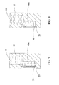
- Figs. 8-9 are sectional views of the present invention in further embodiments of the top surface carrier.
- the micro-droplet generator of the present invention mainly comprises: a main body 10; a spraying plate 20; a vibrating element 30; and a top surface 41, which is placed on a projection or a plan plate.
- the main body 10 has an inner chamber 11, accommodating liquid to be sprayed.
- a lateral opening 12 in the main body 10 connects the chamber 11 with the outside and houses the spraying plate 20. Liquid to be sprayed passes through the opening 12.
- the main body 10 further has an upper side with an inlet 13, through which liquid to be sprayed is poured into the chamber 11.
- the chamber 11 is preferably sized large enough for repeated spraying.
- the inlet 13 preferably has a fixed connection thereto.
- the spraying plate 20 is laid into the opening 12, having a plurality of spraying holes 21 in a dense arrangement.
- the spraying holes 21 define sizes and spraying directions of sprayed micro-droplets, allowing for precise control thereof.
- the spraying plate 20 has an inner side 22 facing the chamber 11 and contacting liquid to be sprayed therein.
- the vibrating element 30 is made of piezoelectric material and placed on the spraying plate 20. Applying electric voltage to the vibrating element 30 causes vibrations thereof, driving vibrations of the spraying plate 20.
- the vibrating element 30 and the spraying plate 20 are glued to each other.
- the spraying plate 20 and the opening 12 have round shapes, while the vibrating element 30 is shaped like a ring.
- vibrations thereof are performed in a direction thereto.
- the main characteristic of the present invention lies in a projection 40 being placed in the chamber 11.
- the projection 40 has an inner end attached to an inner wall of the main body 10 and an opposite outer end carrying the top surface 41 which is parallel to the inner side 22 of the spraying plate 20, leaving a small space 50 in between.
- the space 50 When the vibrating element 30 is driving vibrations of the spraying plate 20, the space 50 has a varying width. As shown in Fig. 3, whenever the spraying plate 20 moves outward, away from the top surface 41 of the projection 40, the space 50 becomes wider, so that liquid flows into the space 50. On the other hand, when the spraying plate 20 moves inward, towards the top surface 41 of the projection 40, the space 50 becomes narrower, so that liquid is pressed through the spraying plate 20 and micro-droplets 51 are generated.
- Liquid flow is controlled by grooves cut into the projection 40.
- a face groove 42 that is shaped like a closed loop is cut into the top surface 41 of a projection 40a.
- a minimum space between the top surface 41 of the projection 40 and the inner side 22 of the spraying plate 20 is maintained, in which liquid stays due to capillary forces.
- a projection 41b is employed having a chamfered top edge 44, so that a minimum space for liquid is provided into which liquid is drawn due to capillary forces.
- Fig. 5 a face groove 42 that is shaped like a closed loop is cut into the top surface 41 of a projection 40a.
- At least one guiding groove 43 is cut into a periphery of a projection 40c, due to capillary forces facilitating flow of liquid to the top surface 41 of the projection 40c.
- capillary forces liquid to be sprayed readily flows into the space 50, even against gravitational forces.
- the top surface carrier may be the following devices. As shown is Fig. 8, a projection 40d shaped like the letter T is horizontally mounted on the main body 10, or as shown in Fig. 9, a plan plate 40e shaped like the letter q is vertically mounted on the main body 10.
- the main characteristic of the present invention lies in installing of the projection 40 in the chamber 11. As shown in Figs. 3 and 4, placing the top surface 41 of the projection 40 close to the inner side 22 of the spraying plate 20 creates the narrow space 50, confining vibrational energy to a small volume, so that energy is saved and power consumption is low, allowing for battery use and prolonged use. Furthermore, effective transmission of vibrations of the spraying plate 20 to liquid inside the space 50 reduces required power for driving liquid through the spraying holes 21, allowing to reduce diameters thereof for a better spraying effect.
- the top surface is also implementable on a plan plate, or the top surface is integrated with the spraying plate 20 forming a chamber, to a similar effect.
- the present invention has a simplified driving system without any need for auxiliary devices, so that manufacturing cost is kept low and volume is reduced. Thereby, mobile applications are readily supported and flat shapes are realizable, making the present invention suitable for applications in ambulant medical devices or air conditioners.
Landscapes
- Special Spraying Apparatus (AREA)
Abstract
Description
- The present invention relates to a micro-droplet generator, particularly to a micro-droplet generator which works by the piezoelectric effect, producing a well-defined flow of tiny droplets.
- Currently available sprayers have two kinds, which work by direct pressure and by vibrations, generating pressure that disperses micro-particles. A common disadvantage of conventional sprayers is the need of large pressure when relatively large particles are generated, resulting in a large noise. For medical applications, spraying of relatively large particles is not required, but precise particle sizes are important. Therefore, sprayers working by vibration have recently been preferred for medical applications. Sprayers of this kind use ultrasound, generated by piezoelectric material, to produce micro-droplets. Shortcomings of these sprayers, however, are high power consumption, the need of a fan to drive micro-droplets into a given direction, a large volume, and non-uniform distribution of micro-particle sizes. Other sprayers which use piezoelectric material have spraying plates with holes of defined diameters to disperse micro-droplets, resulting in considerably reduced power consumption and well-defined micro-droplet sizes. Sprayers of this kind, disclosed in patent or sold on the market, are of two sub-kinds: Sprayers of the first sub-kind by direct vibrational pressure force micro-droplets through spraying plates, sprayers of the second sub-kind have vibrating spraying plates, causing micro-droplets to pass through. Sprayers of the first sub-kind have a higher power consumption than sprayers of the second sub-kind. The latter in some versions use planes that are tapped on, e.g., planes attached to capillary tubes transmitting liquid at ends thereof. These designs, however, have the following shortcomings:
- 1. Energy is easily dissipated.
- 2. Volume is large.
- 3. Manufacturing cost is high.
- 4. Tapped planes attached to capillaries allow only for small spraying angles.
- 5. Spraying is performed with limited effectiveness.
- It is an object of the present invention to provide a micro-droplet generator allowing precise control of flow of micro-droplets.
- Another object of the present invention is to provide a micro-droplet generator having a small volume and low manufacturing cost.
- A further object of the present invention is to provide a micro-droplet generator having a flat shape.
- The present invention can be more fully understood by reference to the following description and accompanying drawings.
- Fig. 1 is a perspective view of the micro-droplet generator of the present invention when disassembled.
- Fig. 2 is a sectional side view of the micro-droplet generator of the present invention.
- Figs. 3 and 4 are schematic illustrations of the operation of the present invention.
- Figs. 5 - 7 are perspective views of the projection of the present invention in other embodiments.
- Figs. 8-9 are sectional views of the present invention in further embodiments of the top surface carrier.
- As shown in Fig. 1, the micro-droplet generator of the present invention mainly comprises: a
main body 10; aspraying plate 20; a vibratingelement 30; and atop surface 41, which is placed on a projection or a plan plate. Themain body 10 has aninner chamber 11, accommodating liquid to be sprayed. Alateral opening 12 in themain body 10 connects thechamber 11 with the outside and houses thespraying plate 20. Liquid to be sprayed passes through theopening 12. - The
main body 10 further has an upper side with aninlet 13, through which liquid to be sprayed is poured into thechamber 11. For mobile applications, e.g., ambulant medicine, thechamber 11 is preferably sized large enough for repeated spraying. For stationary applications, e.g., indoor spraying of liquid from a fixed installed supply, theinlet 13 preferably has a fixed connection thereto. - As shown in Fig. 2, the
spraying plate 20 is laid into theopening 12, having a plurality of sprayingholes 21 in a dense arrangement. The sprayingholes 21 define sizes and spraying directions of sprayed micro-droplets, allowing for precise control thereof. - As further shown in Fig. 2, the
spraying plate 20 has aninner side 22 facing thechamber 11 and contacting liquid to be sprayed therein. - Referring again to Figs. 1 and 2, the vibrating
element 30 is made of piezoelectric material and placed on thespraying plate 20. Applying electric voltage to the vibratingelement 30 causes vibrations thereof, driving vibrations of thespraying plate 20. - The vibrating
element 30 and thespraying plate 20 are glued to each other. Thespraying plate 20 and the opening 12 have round shapes, while the vibratingelement 30 is shaped like a ring. As shown in Figs. 3 and 4, when electric voltage is applied to the vibratingelement 30, vibrations thereof are performed in a direction thereto. - The main characteristic of the present invention lies in a
projection 40 being placed in thechamber 11. Theprojection 40 has an inner end attached to an inner wall of themain body 10 and an opposite outer end carrying thetop surface 41 which is parallel to theinner side 22 of thespraying plate 20, leaving asmall space 50 in between. - When the vibrating
element 30 is driving vibrations of thespraying plate 20, thespace 50 has a varying width. As shown in Fig. 3, whenever thespraying plate 20 moves outward, away from thetop surface 41 of theprojection 40, thespace 50 becomes wider, so that liquid flows into thespace 50. On the other hand, when thespraying plate 20 moves inward, towards thetop surface 41 of theprojection 40, thespace 50 becomes narrower, so that liquid is pressed through thespraying plate 20 and micro-droplets 51 are generated. - Liquid flow is controlled by grooves cut into the
projection 40. As shown in Fig. 5, aface groove 42 that is shaped like a closed loop is cut into thetop surface 41 of aprojection 40a. Thereby, as shown in Fig. 3, a minimum space between thetop surface 41 of theprojection 40 and theinner side 22 of thespraying plate 20 is maintained, in which liquid stays due to capillary forces. As shown in Fig. 6, a projection 41b is employed having a chamferedtop edge 44, so that a minimum space for liquid is provided into which liquid is drawn due to capillary forces. As shown in Fig. 7, at least one guidinggroove 43 is cut into a periphery of aprojection 40c, due to capillary forces facilitating flow of liquid to thetop surface 41 of theprojection 40c. By capillary forces, liquid to be sprayed readily flows into thespace 50, even against gravitational forces. - For accommodating various liquids and casings, the top surface carrier may be the following devices. As shown is Fig. 8, a
projection 40d shaped like the letter T is horizontally mounted on themain body 10, or as shown in Fig. 9, aplan plate 40e shaped like the letter q is vertically mounted on themain body 10. - The main characteristic of the present invention lies in installing of the
projection 40 in thechamber 11. As shown in Figs. 3 and 4, placing thetop surface 41 of theprojection 40 close to theinner side 22 of the sprayingplate 20 creates thenarrow space 50, confining vibrational energy to a small volume, so that energy is saved and power consumption is low, allowing for battery use and prolonged use. Furthermore, effective transmission of vibrations of the sprayingplate 20 to liquid inside thespace 50 reduces required power for driving liquid through the spraying holes 21, allowing to reduce diameters thereof for a better spraying effect. The top surface is also implementable on a plan plate, or the top surface is integrated with the sprayingplate 20 forming a chamber, to a similar effect. - What is more, as compared to conventional art, the present invention has a simplified driving system without any need for auxiliary devices, so that manufacturing cost is kept low and volume is reduced. Thereby, mobile applications are readily supported and flat shapes are realizable, making the present invention suitable for applications in ambulant medical devices or air conditioners.
Claims (19)
- A micro-droplet generator, comprising:a main body (10), having an inside with a chamber (11) accommodating liquid to be sprayed and a lateral opening (12) allowing liquid in said chamber to flow out;a spraying plate (20), placed on said main body at said opening (12) thereof and having a plurality of spraying holes (21) in a dense arrangement as well as an inner side (22) facing said chamber (11) which contacts liquid in said chamber (11) ;a vibrating element (30), glued on said spraying plate (20) and driving vibrations thereof; anda top surface carrier (4), placed inside said chamber and having a top surface (41) that with said inner side of said spraying plate (21) forms an inner part of said chamber (11);wherein upon said vibrations of said spraying plate (20) a narrow space between said inner side of said spraying plate (20) and said top surface (41) with varying width is generated, upon becoming wider sucking in liquid from said chamber (11), and upon becoming narrower pressing out liquid through said spraying holes (21), so that effective spraying of liquid is performed.
- The micro-droplet generator according to claim 1, wherein said top surface carrier (4) is a plan plate (40e) or a projection (40).
- The micro-droplet generator according to claim 1, wherein said top surface carrier (4) has a groove (42).
- The micro-droplet generator according to claim 1, wherein said main body (10) has an upper side with an inlet (13) through which liquid is poured into said chamber (11).
- The micro-droplet generator according to claim 4, wherein said inlet (13) is connected with a stationary supply of liquid, allowing liquid from there to enter said chamber (11).
- The micro-droplet generator according to claim 1, wherein said vibrating element (30) is made of piezoelectric material, thereby vibrating upon application of electric voltage.
- The micro-droplet generator according to claim 6, wherein said vibrating element (30) is shaped like a ring, being attached to a circumference of said spraying plate (20).
- The micro-droplet generator according to claim 2, wherein at least one guiding groove (43)is cut into said projection (40), allowing liquid to flow in between said inner side of said spraying plate (20)and said top surface (41) of said projection (40) .
- The micro-droplet generator according to claim 3, wherein said groove (42) is shaped like a closed loop.
- The micro-droplet generator according to claim 2, wherein said projection (40) has a chamfered top edge (44), allowing liquid to reach flow in between said inner side (22) of said spraying plate (20) and said top surface (41) of said projection (40).
- The micro-droplet generator according to claim 8, wherein said guiding groove (43) is placed on a periphery of said projection (40).
- The micro-droplet generator according to claim 2, wherein said projection (40) has an inner side fixed to said main body (10).
- The micro-droplet generator according to claim 2, wherein said projection (40d) is shaped like the letter T and horizontally mounted inside said main body (10).
- The micro-droplet generator according to claim 2, wherein said plan plate (40e) is shaped like the letter q and vertically mounted inside said main body (10).
- The micro-droplet generator according to claim 2, wherein said plan plate (40e) has an inner side fixed to said main body (10).
- The micro-droplet generator according to claim 2, wherein said projection (40) is integrated with said main body (10) .
- The micro-droplet generator according to claim 2, wherein said plan plate (40e) is integrated with said main body (10).
- The micro-droplet generator according to claim 1, wherein said spraying plate (20) is laid into said opening (12) of said main body (10).
- The micro-droplet generator according to claim 1, wherein said vibrating element (30) drives vibrations of said spraying plate (20) by common electric power.
Priority Applications (1)
| Application Number | Priority Date | Filing Date | Title |
|---|---|---|---|
| EP20050447232 EP1775027B1 (en) | 2005-10-13 | 2005-10-13 | Micro-droplet generator |
Applications Claiming Priority (1)
| Application Number | Priority Date | Filing Date | Title |
|---|---|---|---|
| EP20050447232 EP1775027B1 (en) | 2005-10-13 | 2005-10-13 | Micro-droplet generator |
Publications (2)
| Publication Number | Publication Date |
|---|---|
| EP1775027A1 true EP1775027A1 (en) | 2007-04-18 |
| EP1775027B1 EP1775027B1 (en) | 2012-12-05 |
Family
ID=35797774
Family Applications (1)
| Application Number | Title | Priority Date | Filing Date |
|---|---|---|---|
| EP20050447232 Expired - Lifetime EP1775027B1 (en) | 2005-10-13 | 2005-10-13 | Micro-droplet generator |
Country Status (1)
| Country | Link |
|---|---|
| EP (1) | EP1775027B1 (en) |
Cited By (3)
| Publication number | Priority date | Publication date | Assignee | Title |
|---|---|---|---|---|
| WO2010002953A1 (en) * | 2008-07-03 | 2010-01-07 | The Procter & Gamble Company | Liquid particle emitting device |
| EP2462833A4 (en) * | 2010-07-26 | 2013-06-12 | Yonwoo Co Ltd | Portable electrically-operated liquid-cosmetic mist dispenser |
| CN105890861A (en) * | 2016-04-05 | 2016-08-24 | 南京航空航天大学 | Multifunctional water droplet generator |
Citations (5)
| Publication number | Priority date | Publication date | Assignee | Title |
|---|---|---|---|---|
| US4533082A (en) * | 1981-10-15 | 1985-08-06 | Matsushita Electric Industrial Company, Limited | Piezoelectric oscillated nozzle |
| JPS60187362A (en) * | 1984-03-08 | 1985-09-24 | Matsushita Electric Ind Co Ltd | atomization pump |
| JPS6154252A (en) * | 1984-08-22 | 1986-03-18 | Matsushita Electric Ind Co Ltd | Atomizing pump |
| US5586723A (en) * | 1994-10-07 | 1996-12-24 | Spraying Systems Co. | Liquid spray nozzle with liquid injector/extractor |
| US20020129812A1 (en) * | 2001-03-16 | 2002-09-19 | Craig Litherland | Devices and methods for nebulizing fluids using flow directors |
-
2005
- 2005-10-13 EP EP20050447232 patent/EP1775027B1/en not_active Expired - Lifetime
Patent Citations (5)
| Publication number | Priority date | Publication date | Assignee | Title |
|---|---|---|---|---|
| US4533082A (en) * | 1981-10-15 | 1985-08-06 | Matsushita Electric Industrial Company, Limited | Piezoelectric oscillated nozzle |
| JPS60187362A (en) * | 1984-03-08 | 1985-09-24 | Matsushita Electric Ind Co Ltd | atomization pump |
| JPS6154252A (en) * | 1984-08-22 | 1986-03-18 | Matsushita Electric Ind Co Ltd | Atomizing pump |
| US5586723A (en) * | 1994-10-07 | 1996-12-24 | Spraying Systems Co. | Liquid spray nozzle with liquid injector/extractor |
| US20020129812A1 (en) * | 2001-03-16 | 2002-09-19 | Craig Litherland | Devices and methods for nebulizing fluids using flow directors |
Non-Patent Citations (2)
| Title |
|---|
| PATENT ABSTRACTS OF JAPAN vol. 010, no. 036 (C - 328) 13 February 1986 (1986-02-13) * |
| PATENT ABSTRACTS OF JAPAN vol. 010, no. 214 (C - 362) 25 July 1986 (1986-07-25) * |
Cited By (4)
| Publication number | Priority date | Publication date | Assignee | Title |
|---|---|---|---|---|
| WO2010002953A1 (en) * | 2008-07-03 | 2010-01-07 | The Procter & Gamble Company | Liquid particle emitting device |
| EP2462833A4 (en) * | 2010-07-26 | 2013-06-12 | Yonwoo Co Ltd | Portable electrically-operated liquid-cosmetic mist dispenser |
| CN105890861A (en) * | 2016-04-05 | 2016-08-24 | 南京航空航天大学 | Multifunctional water droplet generator |
| CN105890861B (en) * | 2016-04-05 | 2018-11-27 | 南京航空航天大学 | A kind of multi-functional type water drop generator |
Also Published As
| Publication number | Publication date |
|---|---|
| EP1775027B1 (en) | 2012-12-05 |
Similar Documents
| Publication | Publication Date | Title |
|---|---|---|
| US7784712B2 (en) | Micro-droplet generator | |
| CA2845880C (en) | Disc pump and valve structure | |
| US11090676B2 (en) | Separable membrane improvements | |
| EP2096309A1 (en) | Piezoelectric micro-blower | |
| US10626861B2 (en) | Blower | |
| US6978941B2 (en) | Base isolated nebulizing device and methods | |
| CN1630562A (en) | Liquid spray head and apparatus comprising the spray head and container | |
| TWI487838B (en) | Heat dissipation device and airflow generator thereof | |
| EP2090781A1 (en) | Piezoelectric micro-blower | |
| US20060289673A1 (en) | Micro-droplet generator | |
| EP2182242A3 (en) | Piezoelectric liquid inertia vibration eliminator | |
| WO2010002953A1 (en) | Liquid particle emitting device | |
| US20080277103A1 (en) | Piezoelectric gas ejecting device | |
| EP1775027B1 (en) | Micro-droplet generator | |
| CN107795465B (en) | Micro fluid control device | |
| US20080041972A1 (en) | Spraying structure for an atomizer | |
| EP2101060B1 (en) | Ultrasonic piezoelectric pump | |
| CN100518956C (en) | Micro-fog droplet generating device | |
| JP4844236B2 (en) | NOZZLE, JET GENERATOR, COOLING DEVICE, AND ELECTRONIC DEVICE | |
| JP6650577B2 (en) | Discharge nozzle for liquid discharge | |
| CN1923377A (en) | Atomizer structure | |
| CN201179489Y (en) | Low-energy-consumption ultrasonic atomization device | |
| WO2004085079A1 (en) | Spray generation using a vibrating surface | |
| JP2023016675A (en) | gas transporter | |
| CN222898998U (en) | Atomization spraying assembly and cleaning robot |
Legal Events
| Date | Code | Title | Description |
|---|---|---|---|
| PUAI | Public reference made under article 153(3) epc to a published international application that has entered the european phase |
Free format text: ORIGINAL CODE: 0009012 |
|
| AK | Designated contracting states |
Kind code of ref document: A1 Designated state(s): AT BE BG CH CY CZ DE DK EE ES FI FR GB GR HU IE IS IT LI LT LU LV MC NL PL PT RO SE SI SK TR |
|
| AX | Request for extension of the european patent |
Extension state: AL BA HR MK YU |
|
| 17P | Request for examination filed |
Effective date: 20070905 |
|
| 17Q | First examination report despatched |
Effective date: 20071119 |
|
| AKX | Designation fees paid |
Designated state(s): AT BE BG CH CY CZ DE DK EE ES FI FR GB GR HU IE IS IT LI LT LU LV MC NL PL PT RO SE SI SK TR |
|
| GRAP | Despatch of communication of intention to grant a patent |
Free format text: ORIGINAL CODE: EPIDOSNIGR1 |
|
| GRAS | Grant fee paid |
Free format text: ORIGINAL CODE: EPIDOSNIGR3 |
|
| GRAA | (expected) grant |
Free format text: ORIGINAL CODE: 0009210 |
|
| AK | Designated contracting states |
Kind code of ref document: B1 Designated state(s): AT BE BG CH CY CZ DE DK EE ES FI FR GB GR HU IE IS IT LI LT LU LV MC NL PL PT RO SE SI SK TR |
|
| REG | Reference to a national code |
Ref country code: GB Ref legal event code: FG4D |
|
| REG | Reference to a national code |
Ref country code: CH Ref legal event code: EP |
|
| REG | Reference to a national code |
Ref country code: AT Ref legal event code: REF Ref document number: 586970 Country of ref document: AT Kind code of ref document: T Effective date: 20121215 |
|
| REG | Reference to a national code |
Ref country code: IE Ref legal event code: FG4D |
|
| REG | Reference to a national code |
Ref country code: DE Ref legal event code: R096 Ref document number: 602005037267 Country of ref document: DE Effective date: 20130131 |
|
| REG | Reference to a national code |
Ref country code: DE Ref legal event code: R082 Ref document number: 602005037267 Country of ref document: DE Representative=s name: PRONOVEM - OFFICE VAN MALDEREN S.A., BE |
|
| REG | Reference to a national code |
Ref country code: AT Ref legal event code: MK05 Ref document number: 586970 Country of ref document: AT Kind code of ref document: T Effective date: 20121205 |
|
| PG25 | Lapsed in a contracting state [announced via postgrant information from national office to epo] |
Ref country code: SE Free format text: LAPSE BECAUSE OF FAILURE TO SUBMIT A TRANSLATION OF THE DESCRIPTION OR TO PAY THE FEE WITHIN THE PRESCRIBED TIME-LIMIT Effective date: 20121205 Ref country code: ES Free format text: LAPSE BECAUSE OF FAILURE TO SUBMIT A TRANSLATION OF THE DESCRIPTION OR TO PAY THE FEE WITHIN THE PRESCRIBED TIME-LIMIT Effective date: 20130316 Ref country code: LT Free format text: LAPSE BECAUSE OF FAILURE TO SUBMIT A TRANSLATION OF THE DESCRIPTION OR TO PAY THE FEE WITHIN THE PRESCRIBED TIME-LIMIT Effective date: 20121205 Ref country code: FI Free format text: LAPSE BECAUSE OF FAILURE TO SUBMIT A TRANSLATION OF THE DESCRIPTION OR TO PAY THE FEE WITHIN THE PRESCRIBED TIME-LIMIT Effective date: 20121205 |
|
| REG | Reference to a national code |
Ref country code: NL Ref legal event code: VDEP Effective date: 20121205 |
|
| REG | Reference to a national code |
Ref country code: LT Ref legal event code: MG4D |
|
| PG25 | Lapsed in a contracting state [announced via postgrant information from national office to epo] |
Ref country code: PL Free format text: LAPSE BECAUSE OF FAILURE TO SUBMIT A TRANSLATION OF THE DESCRIPTION OR TO PAY THE FEE WITHIN THE PRESCRIBED TIME-LIMIT Effective date: 20121205 Ref country code: GR Free format text: LAPSE BECAUSE OF FAILURE TO SUBMIT A TRANSLATION OF THE DESCRIPTION OR TO PAY THE FEE WITHIN THE PRESCRIBED TIME-LIMIT Effective date: 20130306 Ref country code: LV Free format text: LAPSE BECAUSE OF FAILURE TO SUBMIT A TRANSLATION OF THE DESCRIPTION OR TO PAY THE FEE WITHIN THE PRESCRIBED TIME-LIMIT Effective date: 20121205 Ref country code: SI Free format text: LAPSE BECAUSE OF FAILURE TO SUBMIT A TRANSLATION OF THE DESCRIPTION OR TO PAY THE FEE WITHIN THE PRESCRIBED TIME-LIMIT Effective date: 20121205 Ref country code: CY Free format text: LAPSE BECAUSE OF FAILURE TO SUBMIT A TRANSLATION OF THE DESCRIPTION OR TO PAY THE FEE WITHIN THE PRESCRIBED TIME-LIMIT Effective date: 20121205 |
|
| PG25 | Lapsed in a contracting state [announced via postgrant information from national office to epo] |
Ref country code: AT Free format text: LAPSE BECAUSE OF FAILURE TO SUBMIT A TRANSLATION OF THE DESCRIPTION OR TO PAY THE FEE WITHIN THE PRESCRIBED TIME-LIMIT Effective date: 20121205 |
|
| PG25 | Lapsed in a contracting state [announced via postgrant information from national office to epo] |
Ref country code: BG Free format text: LAPSE BECAUSE OF FAILURE TO SUBMIT A TRANSLATION OF THE DESCRIPTION OR TO PAY THE FEE WITHIN THE PRESCRIBED TIME-LIMIT Effective date: 20130305 Ref country code: EE Free format text: LAPSE BECAUSE OF FAILURE TO SUBMIT A TRANSLATION OF THE DESCRIPTION OR TO PAY THE FEE WITHIN THE PRESCRIBED TIME-LIMIT Effective date: 20121205 Ref country code: IS Free format text: LAPSE BECAUSE OF FAILURE TO SUBMIT A TRANSLATION OF THE DESCRIPTION OR TO PAY THE FEE WITHIN THE PRESCRIBED TIME-LIMIT Effective date: 20130405 Ref country code: BE Free format text: LAPSE BECAUSE OF FAILURE TO SUBMIT A TRANSLATION OF THE DESCRIPTION OR TO PAY THE FEE WITHIN THE PRESCRIBED TIME-LIMIT Effective date: 20121205 Ref country code: SK Free format text: LAPSE BECAUSE OF FAILURE TO SUBMIT A TRANSLATION OF THE DESCRIPTION OR TO PAY THE FEE WITHIN THE PRESCRIBED TIME-LIMIT Effective date: 20121205 Ref country code: CZ Free format text: LAPSE BECAUSE OF FAILURE TO SUBMIT A TRANSLATION OF THE DESCRIPTION OR TO PAY THE FEE WITHIN THE PRESCRIBED TIME-LIMIT Effective date: 20121205 |
|
| PG25 | Lapsed in a contracting state [announced via postgrant information from national office to epo] |
Ref country code: NL Free format text: LAPSE BECAUSE OF FAILURE TO SUBMIT A TRANSLATION OF THE DESCRIPTION OR TO PAY THE FEE WITHIN THE PRESCRIBED TIME-LIMIT Effective date: 20121205 Ref country code: RO Free format text: LAPSE BECAUSE OF FAILURE TO SUBMIT A TRANSLATION OF THE DESCRIPTION OR TO PAY THE FEE WITHIN THE PRESCRIBED TIME-LIMIT Effective date: 20121205 Ref country code: PT Free format text: LAPSE BECAUSE OF FAILURE TO SUBMIT A TRANSLATION OF THE DESCRIPTION OR TO PAY THE FEE WITHIN THE PRESCRIBED TIME-LIMIT Effective date: 20130405 |
|
| PLBE | No opposition filed within time limit |
Free format text: ORIGINAL CODE: 0009261 |
|
| STAA | Information on the status of an ep patent application or granted ep patent |
Free format text: STATUS: NO OPPOSITION FILED WITHIN TIME LIMIT |
|
| PG25 | Lapsed in a contracting state [announced via postgrant information from national office to epo] |
Ref country code: DK Free format text: LAPSE BECAUSE OF FAILURE TO SUBMIT A TRANSLATION OF THE DESCRIPTION OR TO PAY THE FEE WITHIN THE PRESCRIBED TIME-LIMIT Effective date: 20121205 |
|
| 26N | No opposition filed |
Effective date: 20130906 |
|
| PG25 | Lapsed in a contracting state [announced via postgrant information from national office to epo] |
Ref country code: IT Free format text: LAPSE BECAUSE OF FAILURE TO SUBMIT A TRANSLATION OF THE DESCRIPTION OR TO PAY THE FEE WITHIN THE PRESCRIBED TIME-LIMIT Effective date: 20121205 |
|
| REG | Reference to a national code |
Ref country code: DE Ref legal event code: R097 Ref document number: 602005037267 Country of ref document: DE Effective date: 20130906 |
|
| PG25 | Lapsed in a contracting state [announced via postgrant information from national office to epo] |
Ref country code: MC Free format text: LAPSE BECAUSE OF FAILURE TO SUBMIT A TRANSLATION OF THE DESCRIPTION OR TO PAY THE FEE WITHIN THE PRESCRIBED TIME-LIMIT Effective date: 20121205 |
|
| REG | Reference to a national code |
Ref country code: CH Ref legal event code: PL |
|
| REG | Reference to a national code |
Ref country code: IE Ref legal event code: MM4A |
|
| PG25 | Lapsed in a contracting state [announced via postgrant information from national office to epo] |
Ref country code: LI Free format text: LAPSE BECAUSE OF NON-PAYMENT OF DUE FEES Effective date: 20131031 Ref country code: CH Free format text: LAPSE BECAUSE OF NON-PAYMENT OF DUE FEES Effective date: 20131031 |
|
| PG25 | Lapsed in a contracting state [announced via postgrant information from national office to epo] |
Ref country code: IE Free format text: LAPSE BECAUSE OF NON-PAYMENT OF DUE FEES Effective date: 20131013 |
|
| PG25 | Lapsed in a contracting state [announced via postgrant information from national office to epo] |
Ref country code: TR Free format text: LAPSE BECAUSE OF FAILURE TO SUBMIT A TRANSLATION OF THE DESCRIPTION OR TO PAY THE FEE WITHIN THE PRESCRIBED TIME-LIMIT Effective date: 20121205 |
|
| PG25 | Lapsed in a contracting state [announced via postgrant information from national office to epo] |
Ref country code: LU Free format text: LAPSE BECAUSE OF NON-PAYMENT OF DUE FEES Effective date: 20131013 Ref country code: HU Free format text: LAPSE BECAUSE OF FAILURE TO SUBMIT A TRANSLATION OF THE DESCRIPTION OR TO PAY THE FEE WITHIN THE PRESCRIBED TIME-LIMIT; INVALID AB INITIO Effective date: 20051013 |
|
| REG | Reference to a national code |
Ref country code: FR Ref legal event code: PLFP Year of fee payment: 11 |
|
| REG | Reference to a national code |
Ref country code: FR Ref legal event code: PLFP Year of fee payment: 12 |
|
| REG | Reference to a national code |
Ref country code: FR Ref legal event code: PLFP Year of fee payment: 13 |
|
| REG | Reference to a national code |
Ref country code: FR Ref legal event code: PLFP Year of fee payment: 14 |
|
| PGFP | Annual fee paid to national office [announced via postgrant information from national office to epo] |
Ref country code: DE Payment date: 20241029 Year of fee payment: 20 |
|
| PGFP | Annual fee paid to national office [announced via postgrant information from national office to epo] |
Ref country code: GB Payment date: 20241028 Year of fee payment: 20 |
|
| PGFP | Annual fee paid to national office [announced via postgrant information from national office to epo] |
Ref country code: FR Payment date: 20241025 Year of fee payment: 20 |
|
| REG | Reference to a national code |
Ref country code: DE Ref legal event code: R071 Ref document number: 602005037267 Country of ref document: DE |
|
| REG | Reference to a national code |
Ref country code: GB Ref legal event code: PE20 Expiry date: 20251012 |