EP1772928A1 - Integrated satellite communications outdoor unit - Google Patents
Integrated satellite communications outdoor unit Download PDFInfo
- Publication number
- EP1772928A1 EP1772928A1 EP06120970A EP06120970A EP1772928A1 EP 1772928 A1 EP1772928 A1 EP 1772928A1 EP 06120970 A EP06120970 A EP 06120970A EP 06120970 A EP06120970 A EP 06120970A EP 1772928 A1 EP1772928 A1 EP 1772928A1
- Authority
- EP
- European Patent Office
- Prior art keywords
- outer housing
- outdoor unit
- feed
- reflector
- boom arm
- Prior art date
- Legal status (The legal status is an assumption and is not a legal conclusion. Google has not performed a legal analysis and makes no representation as to the accuracy of the status listed.)
- Granted
Links
- 238000004891 communication Methods 0.000 title claims abstract description 9
- 230000009977 dual effect Effects 0.000 claims abstract description 6
- 230000013011 mating Effects 0.000 claims description 3
- 230000000717 retained effect Effects 0.000 claims description 2
- 238000005058 metal casting Methods 0.000 claims 1
- 230000005540 biological transmission Effects 0.000 description 2
- 230000002452 interceptive effect Effects 0.000 description 2
- 238000004519 manufacturing process Methods 0.000 description 2
- 238000012986 modification Methods 0.000 description 2
- 230000004048 modification Effects 0.000 description 2
- 230000037361 pathway Effects 0.000 description 2
- 238000012546 transfer Methods 0.000 description 2
- 238000009825 accumulation Methods 0.000 description 1
- 230000001010 compromised effect Effects 0.000 description 1
- 238000001816 cooling Methods 0.000 description 1
- 238000005520 cutting process Methods 0.000 description 1
- 230000007812 deficiency Effects 0.000 description 1
- 238000010586 diagram Methods 0.000 description 1
- 238000009826 distribution Methods 0.000 description 1
- 230000017525 heat dissipation Effects 0.000 description 1
- 230000036039 immunity Effects 0.000 description 1
- 238000003780 insertion Methods 0.000 description 1
- 230000037431 insertion Effects 0.000 description 1
- 238000009434 installation Methods 0.000 description 1
- 230000010354 integration Effects 0.000 description 1
- 239000000463 material Substances 0.000 description 1
- 239000002184 metal Substances 0.000 description 1
- 238000000034 method Methods 0.000 description 1
- 230000003287 optical effect Effects 0.000 description 1
- 238000012545 processing Methods 0.000 description 1
- 238000003908 quality control method Methods 0.000 description 1
- 230000009467 reduction Effects 0.000 description 1
- 238000012358 sourcing Methods 0.000 description 1
- 238000012360 testing method Methods 0.000 description 1
- 238000011144 upstream manufacturing Methods 0.000 description 1
Images




Classifications
-
- H—ELECTRICITY
- H01—ELECTRIC ELEMENTS
- H01Q—ANTENNAS, i.e. RADIO AERIALS
- H01Q19/00—Combinations of primary active antenna elements and units with secondary devices, e.g. with quasi-optical devices, for giving the antenna a desired directional characteristic
- H01Q19/10—Combinations of primary active antenna elements and units with secondary devices, e.g. with quasi-optical devices, for giving the antenna a desired directional characteristic using reflecting surfaces
- H01Q19/18—Combinations of primary active antenna elements and units with secondary devices, e.g. with quasi-optical devices, for giving the antenna a desired directional characteristic using reflecting surfaces having two or more spaced reflecting surfaces
- H01Q19/19—Combinations of primary active antenna elements and units with secondary devices, e.g. with quasi-optical devices, for giving the antenna a desired directional characteristic using reflecting surfaces having two or more spaced reflecting surfaces comprising one main concave reflecting surface associated with an auxiliary reflecting surface
- H01Q19/192—Combinations of primary active antenna elements and units with secondary devices, e.g. with quasi-optical devices, for giving the antenna a desired directional characteristic using reflecting surfaces having two or more spaced reflecting surfaces comprising one main concave reflecting surface associated with an auxiliary reflecting surface with dual offset reflectors
-
- H—ELECTRICITY
- H01—ELECTRIC ELEMENTS
- H01Q—ANTENNAS, i.e. RADIO AERIALS
- H01Q19/00—Combinations of primary active antenna elements and units with secondary devices, e.g. with quasi-optical devices, for giving the antenna a desired directional characteristic
- H01Q19/10—Combinations of primary active antenna elements and units with secondary devices, e.g. with quasi-optical devices, for giving the antenna a desired directional characteristic using reflecting surfaces
- H01Q19/12—Combinations of primary active antenna elements and units with secondary devices, e.g. with quasi-optical devices, for giving the antenna a desired directional characteristic using reflecting surfaces wherein the surfaces are concave
- H01Q19/13—Combinations of primary active antenna elements and units with secondary devices, e.g. with quasi-optical devices, for giving the antenna a desired directional characteristic using reflecting surfaces wherein the surfaces are concave the primary radiating source being a single radiating element, e.g. a dipole, a slot, a waveguide termination
-
- H—ELECTRICITY
- H01—ELECTRIC ELEMENTS
- H01Q—ANTENNAS, i.e. RADIO AERIALS
- H01Q19/00—Combinations of primary active antenna elements and units with secondary devices, e.g. with quasi-optical devices, for giving the antenna a desired directional characteristic
- H01Q19/10—Combinations of primary active antenna elements and units with secondary devices, e.g. with quasi-optical devices, for giving the antenna a desired directional characteristic using reflecting surfaces
- H01Q19/12—Combinations of primary active antenna elements and units with secondary devices, e.g. with quasi-optical devices, for giving the antenna a desired directional characteristic using reflecting surfaces wherein the surfaces are concave
- H01Q19/13—Combinations of primary active antenna elements and units with secondary devices, e.g. with quasi-optical devices, for giving the antenna a desired directional characteristic using reflecting surfaces wherein the surfaces are concave the primary radiating source being a single radiating element, e.g. a dipole, a slot, a waveguide termination
- H01Q19/132—Horn reflector antennas; Off-set feeding
Definitions
- Satellite communication systems are known and generally well understood.
- Consumer satellite communications systems such as satellite television and or internet communications typically use a first assembly, referred to as the Outdoor Unit (ODU), including receive electronics and/or transmit electronics, a feed horn and a diplexer or ortho-mode transducer (OMT) mounted on or proximate an antenna dish.
- the ODU is usually mounted proximate the exterior of a consumer's home, positioned in direct line of sight with a satellite.
- An Indoor Unit (IDU) is typically placed indoors and functions to interface the transceiver with end-user equipment.
- the IDU is coupled to the ODU via a communications link supplying power, control, upstream and or downstream signals over electrical and or optical cable(s).
- the ODU includes an LNB (Low Noise Block Downconverter), which is a Low Noise Amplifier and downconverter that simultaneously converts the entire required frequency band received by the dish to a lower frequency for further signal processing and or distribution.
- LNBF an LNB integrated with a feed
- LNB and feed are mounted upon the end of a boom arm that positions the feed at the focal point of the reflector dish.
- the prior ODUs typically have a separate environmentally sealed housing 10 for the transmitter 15 that is attached either at the end or underneath the boom arm 20.
- the transmitter 15 is interconnected, for example by a waveguide 25, with an OMT 30 or diplexer to an LNB 35 that is then also connected to a feed 40.
- the LNB 35 and transmitter 15 have been combined in a common housing to form a transceiver, with the OMT/diplexer and feed then bolted directly to the housing, which is then mounted upon the boom arm at the focal point of the reflector dish as a unitary module having a single mounting point.
- the transceiver module typically includes a heat sink to shed heat generated by the transmitter.
- the heat sink(s) are sized to ensure that the junction temperature of the electronic devices does not rise to a point at which reliability is compromised.
- Figure 1 is a schematic side view of a prior art ODU.
- Figure 2 is a schematic side view of an alternative prior art ODU.
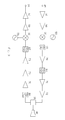
- Figure 3 is a schematic circuit diagram of an integrated transceiver and feed according to the invention.
- Figure 4 is a side view of a single optic ODU with transceiver and feed coupled to the end of a shortened boom arm according to the invention.
- Figure 5 is a front view of Figure 4.
- Figure 6 is a side view of an alternative embodiment of a single optic ODU with transceiver and feed coupled to the end of a shortened boom arm according to the invention.
- Figure 7 is a side view of still another alternative embodiment of a single optic ODU with transceiver and feed coupled to the end of a shortened boom arm according to the invention.
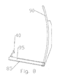
- Figure 8 is a side view of a single optic ODU with transceiver and feed integrated into a common housing coupled directly to the reflector.
- Figure 9 is a side view of a dual optic ODU with sub reflector, transceiver and feed coupled to the end of a shortened boom arm according to the invention.
- a satellite interactive terminal ODU employing an integrated transceiver which incorporates transmit electronics, receive electronics, Orthogonal Mode Transducer (OMT) and transmit reject filter and which may be integrated into the structure of the satellite ODU assembly as the boom arm or attached end to end to a shortened boom arm.
- OMT Orthogonal Mode Transducer
- the ODU integrated transceiver according to the invention may be used, for example, in a microwave or mm-wave, including Ka band satellite interactive terminal with the transmit electronics, receive electronics, (OMT) and transmit reject filter mounted on a satellite dish as a single environmentally sealed module.
- a microwave or mm-wave including Ka band satellite interactive terminal with the transmit electronics, receive electronics, (OMT) and transmit reject filter mounted on a satellite dish as a single environmentally sealed module.
- OMT receive electronics
- the IF input signal 45 path includes preliminary IF amplifier(s) 50 that feed into a reference oscillator 55 driven mixer 60 for upconversion to the desired transmission frequencies.
- the upconverted signals are then fed through first and second filter 65 and amplifier 70 stages before passing through a final power amplifier 72 stage to the OMT 30 or diplexer and feed 40 horn.
- the diplexer is required for co-polar transmit and receive configurations and the OMT 30 in cross polar configurations.
- the RF input signal path from the OMT 30 or diplexer passes through a transmit/reject filter 80 to block passage of the outbound signals from the RF output path and then passes through one or more preamplifier(s) 70.
- the amplified signal is then passed through a frequency filter 65 before downconversion to the IDU input frequencies at a mixer 60 fed by a reference oscillator 55.
- the downconverted IF output passes through output IF amplifier(s) 50.
- the reference oscillator(s) may be phase locked to improve oscillator stability.
- a reference signal for locking the transmit chain may be available from the IDU.
- the transmit reference oscillator may be dual loop phase locked to provide immunity to any phase noise on the IDU reference signal(s).
- the ODU integrated transceiver module may be formed enclosed in an outer housing 85 having a structural aspect for replacing entirely or extending from the end of a shortened boom arm 20 of the antenna as well as a shape with minimal cross section with respect to the signal path of the reflector dish 90.
- the environmentally sealed outer housing 85 of the ODU integrated transceiver module may be cost effectively formed as a cast metal component with internal chambers having waveguide and or microstrip interconnection pathways between them.
- Filter(s) 65 and or portions of the OMT 30 or diplexer and feed 40 horn may be cast or machined into pathways of the outer housing 85.
- the low noise block portion of the circuitry may be formed as a single sub-block. The sub-block arrangement allowing separate sourcing, testing and or tuning of the low noise block portion prior to assembly of the ODU integrated transceiver 95.
- the outer housing 85 also operates as a heat sink for heat dissipation.
- the position of the outer housing 85 away from the reflector in open air improves heat transfer without unacceptably increasing wind load characteristics of the ODU, overall.
- the outer surface(s) of the outer housing 85 may be provided with cooling fins to further optimize heat transfer away from the electrical circuitry.
- the outer housing 85 may be truncated for attachment to the end of a shortened traditional boom arm 20 or, for example as shown in figure 8, formed with an extended structural beam aspect to properly position the feed 40 with respect to the reflector dish 90 while entirely replacing the prior requirement for a separate boom arm. Because the same outer housing 85 may be used with reflector dish(s) 90 of different sizes having a focal point at a range of distances, a variable sized shortened boom arm 20 may be applied. Thereby, a single outer housing 85 configuration may be manufactured and the shortened boom arm 20 adjusted in length to accommodate the required focal length of the reflector dish 90.
- the reflector side of the outer housing 85 may be formed with, for example, a flanged end or a keyed mating socket for simplified but secure mounting insertion of the shortened boom 20 arm retained by a fastener such as a single mounting screw.
- the mounting may be via an end plug 97 of the outer housing 85 that inserts into an open end 99 of the shortened boom arm 20.
- the outer housing 85 has a longitudinal axis.
- the interconnection between the boom arm 20 and the outer housing 85 may be end to end such that the outer housing 85 and boom arm 20 share a common longitudinal axis.
- the resulting ODU has a minimal cross sectional area and a highly aesthetic streamlined appearance.
- the feed 40 may be attached to an end of the outer housing 85 to a surface parallel to the longitudinal axis as shown for example in figures 6 and 8, or to an angled portion 92 of the outer housing 85 that extends away from the longitudinal axis as shown for example in figures 4 and 7.
- the invention may also be configured in a dual optic configuration, for example as shown in figure 9.
- a sub reflector 98 is positioned to re-direct signals between the reflector dish 90 and the feed 40.
- the sub reflector 98 may be coupled to the outer housing 85 or formed as an integral extension of the outer housing 85, further reducing separate part and fastener requirements. In the integrated configuration, the sub reflector 98 also serves as a heat sink for the outer housing 85.
- the components are applied in close proximity, prior requirements for multiple environmentally sealed inter-module interconnection(s) and the transmission losses and costs associated therewith are reduced.
- the mechanical structure forming the boom arm extension and or an end to end replacement thereof may be utilized as a heat sink advantageously located in the open air and having reduced wind load and or snow/ice accumulation characteristics.
- the shortened length required for the boom arm 20 will also be lower cost than a conventional full length boom arm.
- the assembly requirements of an ODU according to the invention are significantly reduced as the prior plurality of fasteners previously applied between the separate components and the boom arm 20 are eliminated.
- the aesthetics of the ODU are greatly increased, because the prior plurality of fasteners, inter-module cabling and clunky appearance in general of the separate modules slung along a significantly larger boom arm and or behind the reflector dish 90 has been eliminated.
Landscapes
- Aerials With Secondary Devices (AREA)
- Radio Relay Systems (AREA)
- Measuring Pulse, Heart Rate, Blood Pressure Or Blood Flow (AREA)
- Input Circuits Of Receivers And Coupling Of Receivers And Audio Equipment (AREA)
- Prostheses (AREA)
- Support Of Aerials (AREA)
- Structure Of Receivers (AREA)
Abstract

Description
- Background
- Satellite communication systems are known and generally well understood. Consumer satellite communications systems such as satellite television and or internet communications typically use a first assembly, referred to as the Outdoor Unit (ODU), including receive electronics and/or transmit electronics, a feed horn and a diplexer or ortho-mode transducer (OMT) mounted on or proximate an antenna dish. The ODU is usually mounted proximate the exterior of a consumer's home, positioned in direct line of sight with a satellite. An Indoor Unit (IDU) is typically placed indoors and functions to interface the transceiver with end-user equipment. The IDU is coupled to the ODU via a communications link supplying power, control, upstream and or downstream signals over electrical and or optical cable(s).
- The ODU includes an LNB (Low Noise Block Downconverter), which is a Low Noise Amplifier and downconverter that simultaneously converts the entire required frequency band received by the dish to a lower frequency for further signal processing and or distribution. The LNBF (an LNB integrated with a feed) and or LNB and feed are mounted upon the end of a boom arm that positions the feed at the focal point of the reflector dish. The prior ODUs, as shown for example in figures 1 and 2, typically have a separate environmentally sealed housing 10 for the transmitter 15 that is attached either at the end or underneath the
boom arm 20. The transmitter 15 is interconnected, for example by awaveguide 25, with an OMT 30 or diplexer to an LNB 35 that is then also connected to afeed 40. Alternatively, the LNB 35 and transmitter 15 have been combined in a common housing to form a transceiver, with the OMT/diplexer and feed then bolted directly to the housing, which is then mounted upon the boom arm at the focal point of the reflector dish as a unitary module having a single mounting point. - The transceiver module typically includes a heat sink to shed heat generated by the transmitter. The heat sink(s) are sized to ensure that the junction temperature of the electronic devices does not rise to a point at which reliability is compromised.
- The increasing competition for reflector antennas adapted for high volume consumer applications has focused attention on improving electrical performance as well as cost reductions resulting from reduced materials and manufacturing cost as well as service efficiencies. Overall aesthetics of an ODU are also a factor for commercial success.
- Therefore, it is an object of the invention to provide an apparatus that overcomes deficiencies in the prior art.
- BRIEF DESCRIPTION OF THE DRAWINGS
The accompanying drawings, which are incorporated in and constitute a part of this specification, illustrate embodiments of the invention and, together with the general and detailed descriptions of the invention appearing herein, serve to explain the principles of the invention. - Figure 1 is a schematic side view of a prior art ODU.
- Figure 2 is a schematic side view of an alternative prior art ODU.
- Figure 3 is a schematic circuit diagram of an integrated transceiver and feed according to the invention.
- Figure 4 is a side view of a single optic ODU with transceiver and feed coupled to the end of a shortened boom arm according to the invention.
- Figure 5 is a front view of Figure 4.
- Figure 6 is a side view of an alternative embodiment of a single optic ODU with transceiver and feed coupled to the end of a shortened boom arm according to the invention.
- Figure 7 is a side view of still another alternative embodiment of a single optic ODU with transceiver and feed coupled to the end of a shortened boom arm according to the invention.
- Figure 8 is a side view of a single optic ODU with transceiver and feed integrated into a common housing coupled directly to the reflector.
- Figure 9 is a side view of a dual optic ODU with sub reflector, transceiver and feed coupled to the end of a shortened boom arm according to the invention.
- Detailed Description
- A satellite interactive terminal ODU employing an integrated transceiver which incorporates transmit electronics, receive electronics, Orthogonal Mode Transducer (OMT) and transmit reject filter and which may be integrated into the structure of the satellite ODU assembly as the boom arm or attached end to end to a shortened boom arm. This affords a high level of integration, cutting installation time, inter module electrical losses and the overall cost of the ODU. Further, overall wind loads and associated structural moment arms of the resulting ODU are reduced.
- The ODU integrated transceiver according to the invention may be used, for example, in a microwave or mm-wave, including Ka band satellite interactive terminal with the transmit electronics, receive electronics, (OMT) and transmit reject filter mounted on a satellite dish as a single environmentally sealed module.
- As shown in figure 3, the
IF input signal 45 path includes preliminary IF amplifier(s) 50 that feed into areference oscillator 55 drivenmixer 60 for upconversion to the desired transmission frequencies. The upconverted signals are then fed through first andsecond filter 65 and amplifier 70 stages before passing through afinal power amplifier 72 stage to the OMT 30 or diplexer and feed 40 horn. The diplexer is required for co-polar transmit and receive configurations and theOMT 30 in cross polar configurations. - Also as shown in figure 3, the RF input signal path from the
OMT 30 or diplexer passes through a transmit/reject filter 80 to block passage of the outbound signals from the RF output path and then passes through one or more preamplifier(s) 70. The amplified signal is then passed through afrequency filter 65 before downconversion to the IDU input frequencies at amixer 60 fed by areference oscillator 55. Before exiting the transceiver for routing to the IDU via theIF output 75, the downconverted IF output passes through output IF amplifier(s) 50. - In both the upconversion and downconversion circuits, the reference oscillator(s) may be phase locked to improve oscillator stability. A reference signal for locking the transmit chain may be available from the IDU. The transmit reference oscillator may be dual loop phase locked to provide immunity to any phase noise on the IDU reference signal(s).
- As shown in figures 4-8, the ODU integrated transceiver module may be formed enclosed in an
outer housing 85 having a structural aspect for replacing entirely or extending from the end of a shortenedboom arm 20 of the antenna as well as a shape with minimal cross section with respect to the signal path of thereflector dish 90. - The environmentally sealed
outer housing 85 of the ODU integrated transceiver module may be cost effectively formed as a cast metal component with internal chambers having waveguide and or microstrip interconnection pathways between them. Filter(s) 65 and or portions of the OMT 30 or diplexer and feed 40 horn may be cast or machined into pathways of theouter housing 85. To improve quality control and production yields, the low noise block portion of the circuitry may be formed as a single sub-block. The sub-block arrangement allowing separate sourcing, testing and or tuning of the low noise block portion prior to assembly of the ODU integratedtransceiver 95. - The
outer housing 85 also operates as a heat sink for heat dissipation. The position of theouter housing 85 away from the reflector in open air improves heat transfer without unacceptably increasing wind load characteristics of the ODU, overall. The outer surface(s) of theouter housing 85 may be provided with cooling fins to further optimize heat transfer away from the electrical circuitry. - The
outer housing 85 may be truncated for attachment to the end of a shortenedtraditional boom arm 20 or, for example as shown in figure 8, formed with an extended structural beam aspect to properly position thefeed 40 with respect to thereflector dish 90 while entirely replacing the prior requirement for a separate boom arm. Because the sameouter housing 85 may be used with reflector dish(s) 90 of different sizes having a focal point at a range of distances, a variable sized shortenedboom arm 20 may be applied. Thereby, a singleouter housing 85 configuration may be manufactured and the shortenedboom arm 20 adjusted in length to accommodate the required focal length of thereflector dish 90. Where theouter housing 85 is attached to a shortenedboom arm 20, the reflector side of theouter housing 85 may be formed with, for example, a flanged end or a keyed mating socket for simplified but secure mounting insertion of the shortenedboom 20 arm retained by a fastener such as a single mounting screw. Alternatively, the mounting may be via anend plug 97 of theouter housing 85 that inserts into anopen end 99 of the shortenedboom arm 20. - The
outer housing 85 has a longitudinal axis. The interconnection between theboom arm 20 and theouter housing 85 may be end to end such that theouter housing 85 andboom arm 20 share a common longitudinal axis. Thereby, the resulting ODU has a minimal cross sectional area and a highly aesthetic streamlined appearance. Thefeed 40 may be attached to an end of theouter housing 85 to a surface parallel to the longitudinal axis as shown for example in figures 6 and 8, or to anangled portion 92 of theouter housing 85 that extends away from the longitudinal axis as shown for example in figures 4 and 7. - The invention may also be configured in a dual optic configuration, for example as shown in figure 9. A
sub reflector 98 is positioned to re-direct signals between thereflector dish 90 and thefeed 40. Thesub reflector 98 may be coupled to theouter housing 85 or formed as an integral extension of theouter housing 85, further reducing separate part and fastener requirements. In the integrated configuration, thesub reflector 98 also serves as a heat sink for theouter housing 85. - Because the components are applied in close proximity, prior requirements for multiple environmentally sealed inter-module interconnection(s) and the transmission losses and costs associated therewith are reduced. Also, because the ODU integrated transceiver is itself integrated into the boom arm, the mechanical structure forming the boom arm extension and or an end to end replacement thereof may be utilized as a heat sink advantageously located in the open air and having reduced wind load and or snow/ice accumulation characteristics. The shortened length required for the
boom arm 20 will also be lower cost than a conventional full length boom arm. Further, the assembly requirements of an ODU according to the invention are significantly reduced as the prior plurality of fasteners previously applied between the separate components and theboom arm 20 are eliminated. - Finally, the aesthetics of the ODU are greatly increased, because the prior plurality of fasteners, inter-module cabling and clunky appearance in general of the separate modules slung along a significantly larger boom arm and or behind the
reflector dish 90 has been eliminated. -
Table of Parts 10 housing 15 transmitter 20 boom arm 25 waveguide 30 OMT 35 LNB 40 feed 45 IF input signal 50 IF amplifier 55 oscillator 60 mixer 65 filter 70 amplifier 72 power amplifier 75 IF output signal 80 transmit/ reject filter 85 outer housing 90 reflector dish 95 transceiver 97 end plug 98 sub reflector 99 open end - Where in the foregoing description reference has been made to ratios, integers, components or modules having known equivalents then such equivalents are herein incorporated as if individually set forth.
- While the present invention has been illustrated by the description of the embodiments thereof, and while the embodiments have been described in considerable detail, it is not the intention of the applicant to restrict or in any way limit the scope of the appended claims to such detail. Additional advantages and modifications will readily appear to those skilled in the art. Therefore, the invention in its broader aspects is not limited to the specific details, representative apparatus, methods, and illustrative examples shown and described. Accordingly, departures may be made from such details without departure from the spirit or scope of applicant's general inventive concept. Further, it is to be appreciated that improvements and/or modifications may be made thereto without departing from the scope or spirit of the present invention as defined by the following claims.
Claims (20)
- An outdoor unit for satellite communications, comprising:A reflector dish;an integrated transceiver module with an outer housing enclosing a transceiver circuit(s) and supporting a feed;the outer housing directly coupled to the reflector, positioning the feed proximate a focal point of the reflector dish.
- The outdoor unit of claim 1, wherein the outer housing is a metal casting.
- The outdoor unit of claim 1, wherein the feed is integral with the outer housing.
- The outdoor unit of claim 1, wherein the transceiver has a phase locked reference oscillator in a receive path.
- The outdoor unit of claim 1, wherein the transceiver has a dual loop phase locked loop in a transmit path.
- The outdoor unit of claim 1, wherein the LNB circuit is a module insertable into a chamber of the outer housing.
- The outdoor unit of claim 1, wherein the reflector dish and feed are in a single optic offset configuration.
- The outdoor unit of claim 1, further including a sub reflector coupled to the outer housing;
the reflector dish and feed horn in a dual optic offset configuration via the sub reflector. - The outdoor unit of claim 7, wherein the sub reflector is integral with the outer housing.
- An outdoor unit for satellite communications, comprising:A reflector dish;an integrated transceiver module with an outer housing enclosing a transceiver circuit(s) and supporting a feed;the outer housing coupled to the end of a boom arm projecting from the reflector, positioning the feed proximate a focal point of the reflector dish.
- The outdoor unit of claim 10, wherein the outer housing has a mating socket into which the end of the boom arm is inserted.
- The outdoor unit of claim 10, wherein the outer housing has an end plug that inserts into an open end of the boom arm.
- The outdoor unit of claim 10, wherein the outer housing is retained upon the end of the boom arm via a single fastener.
- The outdoor unit of claim 10, wherein the outer housing and the boom arm are coupled end to end, sharing a common longitudinal axis.
- An outdoor unit for satellite communications, comprising:A reflector dish;an integrated transceiver module with an outer housing enclosing a transceiver circuit(s) and supporting a feed;the outer housing having a longitudinal axis along which an end of the outer housing is directly coupled to an end of a boom arm projecting from the reflector dish, positioning the feed proximate a focal point of the reflector dish.
- The outdoor unit of claim 15, wherein the outer housing has a mating socket into which the end of the boom arm is inserted.
- The outdoor unit of claim 15, wherein the outer housing has an end plug that inserts into an open end of the boom arm.
- The outdoor unit of claim 15, wherein the feed is coupled to the outer housing at a surface of the outer housing parallel to the longitudinal axis.
- The outdoor unit of claim 15, wherein the feed is coupled to the outer housing at an angled portion of the outer housing.
- The outdoor unit of claim 15, wherein the feed is in the form of a horn.
Applications Claiming Priority (2)
| Application Number | Priority Date | Filing Date | Title |
|---|---|---|---|
| US59655505P | 2005-10-03 | 2005-10-03 | |
| US11/277,300 US20070075909A1 (en) | 2005-10-03 | 2006-03-23 | Integrated Satellite Communications Outdoor Unit |
Publications (2)
| Publication Number | Publication Date |
|---|---|
| EP1772928A1 true EP1772928A1 (en) | 2007-04-11 |
| EP1772928B1 EP1772928B1 (en) | 2009-03-18 |
Family
ID=37671169
Family Applications (1)
| Application Number | Title | Priority Date | Filing Date |
|---|---|---|---|
| EP06120970A Not-in-force EP1772928B1 (en) | 2005-10-03 | 2006-09-20 | Integrated satellite communications outdoor unit |
Country Status (6)
| Country | Link |
|---|---|
| US (1) | US20070075909A1 (en) |
| EP (1) | EP1772928B1 (en) |
| JP (1) | JP2007104674A (en) |
| AT (1) | ATE426258T1 (en) |
| DE (1) | DE602006005754D1 (en) |
| TW (1) | TW200715647A (en) |
Cited By (2)
| Publication number | Priority date | Publication date | Assignee | Title |
|---|---|---|---|---|
| DE102013019177A1 (en) * | 2013-11-18 | 2015-05-21 | Level421 GmbH | Mobile device for transmitting and / or receiving electromagnetic waves |
| EP3657597A1 (en) * | 2018-11-22 | 2020-05-27 | Airbus Oneweb Satellites SAS | Active waveguide transition and rf signal communication system |
Families Citing this family (31)
| Publication number | Priority date | Publication date | Assignee | Title |
|---|---|---|---|---|
| US8515342B2 (en) * | 2005-10-12 | 2013-08-20 | The Directv Group, Inc. | Dynamic current sharing in KA/KU LNB design |
| US8254851B2 (en) | 2008-11-11 | 2012-08-28 | Viasat, Inc. | Integrated orthomode transducer |
| US8542081B2 (en) * | 2008-11-11 | 2013-09-24 | Viasat, Inc. | Molded orthomode transducer |
| US8125400B2 (en) * | 2008-11-14 | 2012-02-28 | Norsat International Inc. | Compact antenna feed assembly and support arm with integrated waveguide |
| US10516219B2 (en) | 2009-04-13 | 2019-12-24 | Viasat, Inc. | Multi-beam active phased array architecture with independent polarization control |
| US8693970B2 (en) * | 2009-04-13 | 2014-04-08 | Viasat, Inc. | Multi-beam active phased array architecture with independant polarization control |
| US10027034B2 (en) * | 2009-06-04 | 2018-07-17 | Ubiquiti Networks, Inc. | Microwave system |
| CN102239599B (en) * | 2009-06-04 | 2015-06-03 | 优波网络公司 | Antenna feed system |
| US8836601B2 (en) | 2013-02-04 | 2014-09-16 | Ubiquiti Networks, Inc. | Dual receiver/transmitter radio devices with choke |
| US8466847B2 (en) * | 2009-06-04 | 2013-06-18 | Ubiquiti Networks, Inc. | Microwave system |
| US10879619B2 (en) | 2009-06-04 | 2020-12-29 | Ubiquiti Inc. | Microwave system |
| US8493279B2 (en) * | 2009-06-04 | 2013-07-23 | Ubiquiti Networks, Inc. | Antenna feed system |
| US9496620B2 (en) | 2013-02-04 | 2016-11-15 | Ubiquiti Networks, Inc. | Radio system for long-range high-speed wireless communication |
| US8981886B2 (en) | 2009-11-06 | 2015-03-17 | Viasat, Inc. | Electromechanical polarization switch |
| US20110109501A1 (en) * | 2009-11-06 | 2011-05-12 | Viasat, Inc. | Automated beam peaking satellite ground terminal |
| TWI407718B (en) * | 2010-05-13 | 2013-09-01 | Wistron Neweb Corp | Optical low-noise block downconverter, multiple dwelling unit and related satellite television system |
| TWI419407B (en) * | 2010-06-21 | 2013-12-11 | Wistron Neweb Corp | Low noise block down-converter with integrated feed |
| CN102468882B (en) * | 2010-11-12 | 2014-09-10 | 启碁科技股份有限公司 | Fiber Optic Low Noise Frequency Converter with Quick Alignment |
| GB201221038D0 (en) * | 2012-11-22 | 2013-01-09 | Satellite Holdings Llc | Antenna |
| US9543635B2 (en) | 2013-02-04 | 2017-01-10 | Ubiquiti Networks, Inc. | Operation of radio devices for long-range high-speed wireless communication |
| US9397820B2 (en) | 2013-02-04 | 2016-07-19 | Ubiquiti Networks, Inc. | Agile duplexing wireless radio devices |
| US8855730B2 (en) | 2013-02-08 | 2014-10-07 | Ubiquiti Networks, Inc. | Transmission and reception of high-speed wireless communication using a stacked array antenna |
| EP3055930B1 (en) | 2013-10-11 | 2019-11-20 | Ubiquiti Inc. | Wireless radio system optimization by persistent spectrum analysis |
| US9172605B2 (en) | 2014-03-07 | 2015-10-27 | Ubiquiti Networks, Inc. | Cloud device identification and authentication |
| US20150256355A1 (en) | 2014-03-07 | 2015-09-10 | Robert J. Pera | Wall-mounted interactive sensing and audio-visual node devices for networked living and work spaces |
| US9912053B2 (en) | 2014-03-17 | 2018-03-06 | Ubiquiti Networks, Inc. | Array antennas having a plurality of directional beams |
| CN104981941B (en) | 2014-04-01 | 2018-02-02 | 优倍快网络公司 | antenna assembly |
| US11329391B2 (en) * | 2015-02-27 | 2022-05-10 | Viasat, Inc. | Enhanced directivity feed and feed array |
| WO2019069546A1 (en) | 2017-10-03 | 2019-04-11 | 株式会社村田製作所 | ANTENNA MODULE AND ITS INSPECTION METHOD |
| CN110336966B (en) * | 2019-05-29 | 2022-07-12 | 泉州天地星电子有限公司 | Combined satellite television receiver |
| US11909096B2 (en) * | 2020-11-25 | 2024-02-20 | Antenna Research Associates, Inc. | Mechanically adjustable antenna positioning system |
Citations (2)
| Publication number | Priority date | Publication date | Assignee | Title |
|---|---|---|---|---|
| WO1999063624A1 (en) * | 1998-06-02 | 1999-12-09 | Cambridge Industries Limited | Antenna feed and a reflector antenna system and a low noise (lnb) receiver, both with such an antenna feed |
| WO2002073740A1 (en) | 2001-03-12 | 2002-09-19 | Wildblue Communications, Inc. | Multi-band antenna for bundled broadband satellite internet access and dbs television service |
Family Cites Families (6)
| Publication number | Priority date | Publication date | Assignee | Title |
|---|---|---|---|---|
| JPS6234808U (en) * | 1985-08-20 | 1987-02-28 | ||
| JP2588660B2 (en) * | 1991-12-27 | 1997-03-05 | 富士通株式会社 | Mounting structure of outdoor transceiver for antenna |
| US5448254A (en) * | 1994-03-31 | 1995-09-05 | Thomson Consumer Electronics, Inc. | Mechanism for mounting a receiving/transmitting horn in a satellite dish |
| US6445359B1 (en) * | 2000-09-29 | 2002-09-03 | Hughes Electronics Corporation | Low noise block down converter adapter with built-in multi-switch for a satellite dish antenna |
| US7849491B2 (en) * | 2002-12-10 | 2010-12-07 | Onlive, Inc. | Apparatus and method for wireless video gaming |
| US7109938B2 (en) * | 2004-10-29 | 2006-09-19 | Motorola, Inc. | Tapered slot feed for an automotive radar antenna |
-
2006
- 2006-03-23 US US11/277,300 patent/US20070075909A1/en not_active Abandoned
- 2006-09-20 AT AT06120970T patent/ATE426258T1/en not_active IP Right Cessation
- 2006-09-20 DE DE602006005754T patent/DE602006005754D1/en active Active
- 2006-09-20 EP EP06120970A patent/EP1772928B1/en not_active Not-in-force
- 2006-10-02 JP JP2006270279A patent/JP2007104674A/en active Pending
- 2006-10-03 TW TW095136625A patent/TW200715647A/en unknown
Patent Citations (2)
| Publication number | Priority date | Publication date | Assignee | Title |
|---|---|---|---|---|
| WO1999063624A1 (en) * | 1998-06-02 | 1999-12-09 | Cambridge Industries Limited | Antenna feed and a reflector antenna system and a low noise (lnb) receiver, both with such an antenna feed |
| WO2002073740A1 (en) | 2001-03-12 | 2002-09-19 | Wildblue Communications, Inc. | Multi-band antenna for bundled broadband satellite internet access and dbs television service |
Cited By (4)
| Publication number | Priority date | Publication date | Assignee | Title |
|---|---|---|---|---|
| DE102013019177A1 (en) * | 2013-11-18 | 2015-05-21 | Level421 GmbH | Mobile device for transmitting and / or receiving electromagnetic waves |
| EP3657597A1 (en) * | 2018-11-22 | 2020-05-27 | Airbus Oneweb Satellites SAS | Active waveguide transition and rf signal communication system |
| WO2020104358A1 (en) * | 2018-11-22 | 2020-05-28 | Airbus Oneweb Satellites S.A.S | Active waveguide transition and rf signal communication system |
| US11984636B2 (en) | 2018-11-22 | 2024-05-14 | Airbus Oneweb Satellites Sas | Active waveguide transition having a probe and RF amplifier system and which is usable in a transmit/receive communication system |
Also Published As
| Publication number | Publication date |
|---|---|
| ATE426258T1 (en) | 2009-04-15 |
| DE602006005754D1 (en) | 2009-04-30 |
| TW200715647A (en) | 2007-04-16 |
| US20070075909A1 (en) | 2007-04-05 |
| EP1772928B1 (en) | 2009-03-18 |
| JP2007104674A (en) | 2007-04-19 |
Similar Documents
| Publication | Publication Date | Title |
|---|---|---|
| EP1772928B1 (en) | Integrated satellite communications outdoor unit | |
| US6720933B2 (en) | Dual band satellite communications antenna feed | |
| US7102896B2 (en) | Electronic component module | |
| US7130590B2 (en) | Transceiver assembly | |
| US7474173B2 (en) | Cross-polar and co-polar transceiver | |
| US20190067836A1 (en) | Spatial power-combining devices and antenna assemblies | |
| US20050259026A1 (en) | Circular polarity elliptical horn antenna | |
| US20110237299A1 (en) | Gps mast module and mobile radio installation | |
| CN108808224A (en) | MASSIVE mimo antennas | |
| US12062828B2 (en) | Resonant cavity filter comprising a dielectric resonator mounted to a conductive housing by a dielectric fastener located within a longitudinal bore of the dielectric resonator | |
| EP0110324A1 (en) | Microwave receiving apparatus using a waveguide filter | |
| US6914787B2 (en) | Electronic component module | |
| CN1331273C (en) | Communications antenna system and mobile transmit and receive reflector antenna | |
| US20030184487A1 (en) | Reflector/feed antenna with reflector mounted waveguide diplexer-OMT | |
| KR100957645B1 (en) | High Efficiency Broadband Cagegrain Antenna and Feeder Feeder Structure Using Non-Radiated Microstrip Line | |
| US6384796B1 (en) | Antenna for radiating and receiving electromagnetic waves | |
| CN211240266U (en) | Circuit board, antenna assembly and dual polarized antenna | |
| Chang et al. | Commercial Ka and Ku bands reflector antennas | |
| KR101840834B1 (en) | Spatial power combiner for millimeter wave using horizontal electric field | |
| CN221508473U (en) | Antenna and smart glasses | |
| CN119560754A (en) | A high-power broadband duplexer | |
| CN118572350B (en) | Electric heating integrated design method for movable antenna machine of satellite-borne communication system | |
| US20250316907A1 (en) | Feeding apparatus, antenna apparatus, and communication device | |
| CN114899570B (en) | Microstrip-waveguide conversion structure with out-of-band suppression function | |
| JP2805889B2 (en) | Outdoor equipment for small ground stations |
Legal Events
| Date | Code | Title | Description |
|---|---|---|---|
| PUAI | Public reference made under article 153(3) epc to a published international application that has entered the european phase |
Free format text: ORIGINAL CODE: 0009012 |
|
| AK | Designated contracting states |
Kind code of ref document: A1 Designated state(s): AT BE BG CH CY CZ DE DK EE ES FI FR GB GR HU IE IS IT LI LT LU LV MC NL PL PT RO SE SI SK TR |
|
| AX | Request for extension of the european patent |
Extension state: AL BA HR MK YU |
|
| 17P | Request for examination filed |
Effective date: 20070905 |
|
| 17Q | First examination report despatched |
Effective date: 20071005 |
|
| AKX | Designation fees paid |
Designated state(s): AT BE BG CH CY CZ DE DK EE ES FI FR GB GR HU IE IS IT LI LT LU LV MC NL PL PT RO SE SI SK TR |
|
| GRAP | Despatch of communication of intention to grant a patent |
Free format text: ORIGINAL CODE: EPIDOSNIGR1 |
|
| GRAS | Grant fee paid |
Free format text: ORIGINAL CODE: EPIDOSNIGR3 |
|
| GRAA | (expected) grant |
Free format text: ORIGINAL CODE: 0009210 |
|
| AK | Designated contracting states |
Kind code of ref document: B1 Designated state(s): AT BE BG CH CY CZ DE DK EE ES FI FR GB GR HU IE IS IT LI LT LU LV MC NL PL PT RO SE SI SK TR |
|
| REG | Reference to a national code |
Ref country code: GB Ref legal event code: FG4D |
|
| REG | Reference to a national code |
Ref country code: CH Ref legal event code: EP |
|
| REG | Reference to a national code |
Ref country code: IE Ref legal event code: FG4D |
|
| REF | Corresponds to: |
Ref document number: 602006005754 Country of ref document: DE Date of ref document: 20090430 Kind code of ref document: P |
|
| PG25 | Lapsed in a contracting state [announced via postgrant information from national office to epo] |
Ref country code: SI Free format text: LAPSE BECAUSE OF FAILURE TO SUBMIT A TRANSLATION OF THE DESCRIPTION OR TO PAY THE FEE WITHIN THE PRESCRIBED TIME-LIMIT Effective date: 20090318 Ref country code: NL Free format text: LAPSE BECAUSE OF FAILURE TO SUBMIT A TRANSLATION OF THE DESCRIPTION OR TO PAY THE FEE WITHIN THE PRESCRIBED TIME-LIMIT Effective date: 20090318 Ref country code: LT Free format text: LAPSE BECAUSE OF FAILURE TO SUBMIT A TRANSLATION OF THE DESCRIPTION OR TO PAY THE FEE WITHIN THE PRESCRIBED TIME-LIMIT Effective date: 20090318 Ref country code: FI Free format text: LAPSE BECAUSE OF FAILURE TO SUBMIT A TRANSLATION OF THE DESCRIPTION OR TO PAY THE FEE WITHIN THE PRESCRIBED TIME-LIMIT Effective date: 20090318 |
|
| PG25 | Lapsed in a contracting state [announced via postgrant information from national office to epo] |
Ref country code: PL Free format text: LAPSE BECAUSE OF FAILURE TO SUBMIT A TRANSLATION OF THE DESCRIPTION OR TO PAY THE FEE WITHIN THE PRESCRIBED TIME-LIMIT Effective date: 20090318 Ref country code: AT Free format text: LAPSE BECAUSE OF FAILURE TO SUBMIT A TRANSLATION OF THE DESCRIPTION OR TO PAY THE FEE WITHIN THE PRESCRIBED TIME-LIMIT Effective date: 20090318 Ref country code: SE Free format text: LAPSE BECAUSE OF FAILURE TO SUBMIT A TRANSLATION OF THE DESCRIPTION OR TO PAY THE FEE WITHIN THE PRESCRIBED TIME-LIMIT Effective date: 20090618 Ref country code: LV Free format text: LAPSE BECAUSE OF FAILURE TO SUBMIT A TRANSLATION OF THE DESCRIPTION OR TO PAY THE FEE WITHIN THE PRESCRIBED TIME-LIMIT Effective date: 20090318 |
|
| NLV1 | Nl: lapsed or annulled due to failure to fulfill the requirements of art. 29p and 29m of the patents act | ||
| PG25 | Lapsed in a contracting state [announced via postgrant information from national office to epo] |
Ref country code: BE Free format text: LAPSE BECAUSE OF FAILURE TO SUBMIT A TRANSLATION OF THE DESCRIPTION OR TO PAY THE FEE WITHIN THE PRESCRIBED TIME-LIMIT Effective date: 20090318 |
|
| PG25 | Lapsed in a contracting state [announced via postgrant information from national office to epo] |
Ref country code: CZ Free format text: LAPSE BECAUSE OF FAILURE TO SUBMIT A TRANSLATION OF THE DESCRIPTION OR TO PAY THE FEE WITHIN THE PRESCRIBED TIME-LIMIT Effective date: 20090318 Ref country code: EE Free format text: LAPSE BECAUSE OF FAILURE TO SUBMIT A TRANSLATION OF THE DESCRIPTION OR TO PAY THE FEE WITHIN THE PRESCRIBED TIME-LIMIT Effective date: 20090318 Ref country code: PT Free format text: LAPSE BECAUSE OF FAILURE TO SUBMIT A TRANSLATION OF THE DESCRIPTION OR TO PAY THE FEE WITHIN THE PRESCRIBED TIME-LIMIT Effective date: 20090826 Ref country code: ES Free format text: LAPSE BECAUSE OF FAILURE TO SUBMIT A TRANSLATION OF THE DESCRIPTION OR TO PAY THE FEE WITHIN THE PRESCRIBED TIME-LIMIT Effective date: 20090629 |
|
| PG25 | Lapsed in a contracting state [announced via postgrant information from national office to epo] |
Ref country code: IS Free format text: LAPSE BECAUSE OF FAILURE TO SUBMIT A TRANSLATION OF THE DESCRIPTION OR TO PAY THE FEE WITHIN THE PRESCRIBED TIME-LIMIT Effective date: 20090718 Ref country code: RO Free format text: LAPSE BECAUSE OF FAILURE TO SUBMIT A TRANSLATION OF THE DESCRIPTION OR TO PAY THE FEE WITHIN THE PRESCRIBED TIME-LIMIT Effective date: 20090318 Ref country code: SK Free format text: LAPSE BECAUSE OF FAILURE TO SUBMIT A TRANSLATION OF THE DESCRIPTION OR TO PAY THE FEE WITHIN THE PRESCRIBED TIME-LIMIT Effective date: 20090318 |
|
| RAP2 | Party data changed (patent owner data changed or rights of a patent transferred) |
Owner name: ASC SIGNAL INTERNATIONAL CORPORATION |
|
| RAP2 | Party data changed (patent owner data changed or rights of a patent transferred) |
Owner name: RAVEN MANUFACTURING LIMITED |
|
| PLBE | No opposition filed within time limit |
Free format text: ORIGINAL CODE: 0009261 |
|
| STAA | Information on the status of an ep patent application or granted ep patent |
Free format text: STATUS: NO OPPOSITION FILED WITHIN TIME LIMIT |
|
| PG25 | Lapsed in a contracting state [announced via postgrant information from national office to epo] |
Ref country code: BG Free format text: LAPSE BECAUSE OF FAILURE TO SUBMIT A TRANSLATION OF THE DESCRIPTION OR TO PAY THE FEE WITHIN THE PRESCRIBED TIME-LIMIT Effective date: 20090618 Ref country code: DK Free format text: LAPSE BECAUSE OF FAILURE TO SUBMIT A TRANSLATION OF THE DESCRIPTION OR TO PAY THE FEE WITHIN THE PRESCRIBED TIME-LIMIT Effective date: 20090318 |
|
| REG | Reference to a national code |
Ref country code: GB Ref legal event code: 732E Free format text: REGISTERED BETWEEN 20100121 AND 20100127 |
|
| 26N | No opposition filed |
Effective date: 20091221 |
|
| PG25 | Lapsed in a contracting state [announced via postgrant information from national office to epo] |
Ref country code: MC Free format text: LAPSE BECAUSE OF NON-PAYMENT OF DUE FEES Effective date: 20090930 |
|
| REG | Reference to a national code |
Ref country code: IE Ref legal event code: MM4A |
|
| REG | Reference to a national code |
Ref country code: FR Ref legal event code: ST Effective date: 20100531 |
|
| PG25 | Lapsed in a contracting state [announced via postgrant information from national office to epo] |
Ref country code: FR Free format text: LAPSE BECAUSE OF NON-PAYMENT OF DUE FEES Effective date: 20090930 Ref country code: IE Free format text: LAPSE BECAUSE OF NON-PAYMENT OF DUE FEES Effective date: 20090920 |
|
| PG25 | Lapsed in a contracting state [announced via postgrant information from national office to epo] |
Ref country code: GR Free format text: LAPSE BECAUSE OF FAILURE TO SUBMIT A TRANSLATION OF THE DESCRIPTION OR TO PAY THE FEE WITHIN THE PRESCRIBED TIME-LIMIT Effective date: 20090619 |
|
| PG25 | Lapsed in a contracting state [announced via postgrant information from national office to epo] |
Ref country code: IT Free format text: LAPSE BECAUSE OF FAILURE TO SUBMIT A TRANSLATION OF THE DESCRIPTION OR TO PAY THE FEE WITHIN THE PRESCRIBED TIME-LIMIT Effective date: 20090318 |
|
| PG25 | Lapsed in a contracting state [announced via postgrant information from national office to epo] |
Ref country code: LU Free format text: LAPSE BECAUSE OF NON-PAYMENT OF DUE FEES Effective date: 20090920 |
|
| REG | Reference to a national code |
Ref country code: CH Ref legal event code: PL |
|
| PG25 | Lapsed in a contracting state [announced via postgrant information from national office to epo] |
Ref country code: HU Free format text: LAPSE BECAUSE OF FAILURE TO SUBMIT A TRANSLATION OF THE DESCRIPTION OR TO PAY THE FEE WITHIN THE PRESCRIBED TIME-LIMIT Effective date: 20090919 |
|
| PG25 | Lapsed in a contracting state [announced via postgrant information from national office to epo] |
Ref country code: CH Free format text: LAPSE BECAUSE OF NON-PAYMENT OF DUE FEES Effective date: 20100930 Ref country code: LI Free format text: LAPSE BECAUSE OF NON-PAYMENT OF DUE FEES Effective date: 20100930 |
|
| PG25 | Lapsed in a contracting state [announced via postgrant information from national office to epo] |
Ref country code: TR Free format text: LAPSE BECAUSE OF FAILURE TO SUBMIT A TRANSLATION OF THE DESCRIPTION OR TO PAY THE FEE WITHIN THE PRESCRIBED TIME-LIMIT Effective date: 20090318 |
|
| PG25 | Lapsed in a contracting state [announced via postgrant information from national office to epo] |
Ref country code: CY Free format text: LAPSE BECAUSE OF FAILURE TO SUBMIT A TRANSLATION OF THE DESCRIPTION OR TO PAY THE FEE WITHIN THE PRESCRIBED TIME-LIMIT Effective date: 20090318 |
|
| REG | Reference to a national code |
Ref country code: DE Ref legal event code: R082 Ref document number: 602006005754 Country of ref document: DE Representative=s name: EISENFUEHR, SPEISER & PARTNER, DE Ref country code: DE Ref legal event code: R082 Ref document number: 602006005754 Country of ref document: DE Representative=s name: EISENFUEHR SPEISER PATENTANWAELTE RECHTSANWAEL, DE |
|
| REG | Reference to a national code |
Ref country code: DE Ref legal event code: R082 Ref document number: 602006005754 Country of ref document: DE Representative=s name: EISENFUEHR SPEISER PATENTANWAELTE RECHTSANWAEL, DE |
|
| REG | Reference to a national code |
Ref country code: GB Ref legal event code: 732E Free format text: REGISTERED BETWEEN 20140508 AND 20140514 |
|
| REG | Reference to a national code |
Ref country code: DE Ref legal event code: R081 Ref document number: 602006005754 Country of ref document: DE Owner name: RAVEN GROUP LIMITED, GB Free format text: FORMER OWNER: RAVEN MANUFACTURING LTD., ACCRINGTON, GB Effective date: 20140428 Ref country code: DE Ref legal event code: R082 Ref document number: 602006005754 Country of ref document: DE Representative=s name: EISENFUEHR SPEISER PATENTANWAELTE RECHTSANWAEL, DE Effective date: 20140428 Ref country code: DE Ref legal event code: R082 Ref document number: 602006005754 Country of ref document: DE Representative=s name: EISENFUEHR SPEISER PATENTANWAELTE RECHTSANWAEL, DE Effective date: 20111114 Ref country code: DE Ref legal event code: R081 Ref document number: 602006005754 Country of ref document: DE Owner name: RAVEN GROUP LIMITED, GB Free format text: FORMER OWNER: RAVEN MANUFACTURING LTD., ACCRINGTON, LANCASHIRE, GB Effective date: 20140428 |
|
| PGFP | Annual fee paid to national office [announced via postgrant information from national office to epo] |
Ref country code: GB Payment date: 20221011 Year of fee payment: 17 Ref country code: DE Payment date: 20221012 Year of fee payment: 17 |
|
| P01 | Opt-out of the competence of the unified patent court (upc) registered |
Effective date: 20230403 |
|
| REG | Reference to a national code |
Ref country code: DE Ref legal event code: R119 Ref document number: 602006005754 Country of ref document: DE |
|
| GBPC | Gb: european patent ceased through non-payment of renewal fee |
Effective date: 20230920 |
|
| PG25 | Lapsed in a contracting state [announced via postgrant information from national office to epo] |
Ref country code: GB Free format text: LAPSE BECAUSE OF NON-PAYMENT OF DUE FEES Effective date: 20230920 |
|
| PG25 | Lapsed in a contracting state [announced via postgrant information from national office to epo] |
Ref country code: GB Free format text: LAPSE BECAUSE OF NON-PAYMENT OF DUE FEES Effective date: 20230920 Ref country code: DE Free format text: LAPSE BECAUSE OF NON-PAYMENT OF DUE FEES Effective date: 20240403 |